

Page 1

Operating instruction RAPTOR 4all & 4you
0
MOBILITY MADE SIMPLE!
Operating instructions
Service booklet
RAPTOR 4all Compact bike
RAPTOR 4you Compact bike
Page 2

Operating instruction RAPTOR 4all & 4you
1
Contents
1Preface ............................................................................................................................................... 3
2Legend ................................................................................................................................................ 3
3CE Declaration of Conformity / other information ............................................................................... 3
3.1Classification ............................................................................................................................... 3
3.2Declaration of Conformity ........................................................................................................... 3
3.3Manufacturer ............................................................................................................................... 3
4Scope of delivery ................................................................................................................................ 3
5Introduction ......................................................................................................................................... 4
6Product description / purpose ............................................................................................................. 4
7Acceptable usage and operating conditions / places of use .............................................................. 4
8Technical specifications ..................................................................................................................... 5
8.1Product weight ............................................................................................................................ 5
8.2Load weight ................................................................................................................................ 5
8.3Ground clearance and turning circle ........................................................................................... 5
8.4Service life .................................................................................................................................. 5
8.5Basic equipment & dimensions .................................................................................................. 5
9Rating plate ........................................................................................................................................ 6
10Commissioning ................................................................................................................................... 6
11Hand-over ........................................................................................................................................... 6
12Safety instructions – prior to driving / use ......................................................................................... 6
13Safety instructions – while driving / using .......................................................................................... 7
14Safety instructions regarding obstacles ............................................................................................. 8
15Safety instructions regarding dangerous locations and dangerous situations ................................... 9
16Functional elements ........................................................................................................................... 9
16.1
Pedal bearing support & crank ........................................................................................... 9
16.1.1Seating position ............................................................................................................. 9
16.1.2Pedal bearing position ................................................................................................. 10
16.1.3Crank length and grip width ......................................................................................... 10
16.2Grips ......................................................................................................................................... 11
16.3Gear shift .................................................................................................................................. 11
16.3.1Chain shift .................................................................................................................... 11
16.3.2Hub gears .................................................................................................................... 13
16.4Brakes ....................................................................................................................................... 13
16.4.1Rim and disc brakes .................................................................................................... 13
16.4.2Parking brake ............................................................................................................... 14
16.5Components ............................................................................................................................. 14
Page 3

Operating instruction RAPTOR 4all & 4you
2
17Backrest ............................................................................................................................................ 15
18Seat system ...................................................................................................................................... 16
19Neck rest .......................................................................................................................................... 16
19.1Neck rest height adjustment ..................................................................................................... 16
19.2Neck rest angle adjustment ...................................................................................................... 16
20Collision guard .................................................................................................................................. 17
20.1Collision guard mount ............................................................................................................... 17
20.2Mounting the collision guard ..................................................................................................... 17
21Running wheels ................................................................................................................................ 18
21.1Removing and attaching the running wheels ........................................................................... 18
21.2
Checking and setting the wheel tracking ......................................................................... 18
22Removal and attachment of the axle tube ........................................................................................ 20
23Adaptation and decoupling the drive unit ......................................................................................... 20
23.1Safety instructions .................................................................................................................... 20
23.2Terminology .............................................................................................................................. 20
23.3Adapting the drive unit .............................................................................................................. 21
23.4Decoupling the drive unit .......................................................................................................... 22
24Storage ............................................................................................................................................. 23
25Transport .......................................................................................................................................... 23
26Malfunctions ..................................................................................................................................... 23
27Cleaning and care ............................................................................................................................ 23
28Maintenance ..................................................................................................................................... 24
28.1General instructions .................................................................................................................. 24
28.2Service schedules ..................................................................................................................... 24
28.3Proof of maintenance ................................................................................................................ 25
29Disposal & Recycling ........................................................................................................................ 25
30Re-use .............................................................................................................................................. 25
31Warranty ........................................................................................................................................... 26
32Liability .............................................................................................................................................. 26
33Appendix: Avoiding crossed gears with the chain shift .................................................................... 27
34Appendix: Tightening torques, securing details and tools ................................................................ 28
35Appendix: Medical product passport / record of training .................................................................. 29
36Appendix: Hand-over certificate ....................................................................................................... 30
36.1Required compliance criteria to authorise use ......................................................................... 30
36.2Check list for training the user .................................................................................................. 31
37Appendix: Inspection lists .................................................................................................... ............. 32
Page 4

Operating instruction RAPTOR 4all & 4you
3
1 Preface
Dear Customer,
Congratulations on purchasing your new
PRO ACTIV product. You have bought a
quality product which has been especially
customised to meet your requirements.
We have put together some instructions about
its proper and safe use in the following
document. Please read these instructions
before using the product.
Throughout these operating instructions, the
operation of standard components is
explained. If you have individual solutions or
non-standard components on your product,
your dealer or we at PRO ACTIV would be
happy to deal with any questions you may
have about handling it.
The only difference between the compact bikes
RAPTOR 4all & RAPTOR 4you are the design
of the frame when ordering (or in the number
of frame parameters that can be selected). The
operating instructions are therefore identical.
If you have any further questions about this or
any of our other products, we would be glad to
be at your disposal.
Enjoy your trips and the best possible mobility.
Your PRO ACTIV team
2 Legend
The symbols used in these operating
instructions have the following meanings:
Manufacturer
Warnings and safety instructions
Serial number
Additional information
Assembly instructions for the dealer (see
table of contents)
3 CE Declaration of Conformity /
other information
3.1 Classification
The RAPTOR 4all & 4you Compact bike
(referred to as a "product" below) is classified
as a class I product.
3.2 Declaration of Conformity
PRO ACTIV Reha-Technik GmbH declares in
the context of an individual declaration of
conformity that the respective product has
been developed and manufactured according
to the relevant provisions of
EC Directive 93/42/EEC 2007.
If the product is adapted in a manner which
has not been agreed by PRO ACTIV RehaTechnik GmbH, this declaration becomes void.
3.3 Manufacturer
PRO ACTIV Reha-Technik GmbH
Im Hofstätt 11
D-72359 Dotternhausen
Tel. +49 7427 9480-0
Fax +49 7427 9480-7025
E-Mail: info@proactiv-gmbh.de
Web: www.proactiv-gmbh.com
4 Scope of delivery
The delivery includes the product configured in
accordance with the order, with chassis
stands, operating instructions including record
of training / hand-over certificate and
inspection lists. You can view the basic
equipment in chapter "Technical
specifications". As per your order, the product
is equipped with additional recommended
accessories, such as e.g., lighting, safet y
pennon and hip strap.
Please check that the delivery is complete after
you have received your product.
Page 5

Operating instruction RAPTOR 4all & 4you
4
The product is tested to ensure it is completely
functional prior to shipping. If your product has
been damaged during transit, please contact
your dealer or PRO ACTIV immediately.
5 Introduction
Before starting your journey for the first
time, familiarise yourself with these operating
instructions paying particular attention to the
safety information and hazard warnings
contained within them.
If you are not sure how to handle the
product or if technical faults occur, please
contact your dealer or PRO ACTIV before
using it.
Never leave the product unattended.
6 Product description / purpose
The product is a compact bike comprising a
drive unit and a product frame that is
designated as chassis. The user lies in the
product and propels using crank movements
with their hands and arms.
The product assists the user with their mobility.
It is easier to cover longer distances with
ergonomic movement processes (similar to
using one's own wheelchair) and it is also
possible to take bicycle tours with pedestrians.
This expands the activity radius.
The downhill speed can be regulated via the
product's braking systems, so that downhill
slopes can be travelled on safely.
When hand-biking, the seating posture in the
wheelchair as well as the static straighten the
spinal column are promoted by a
physiologically sensible and ergonomic training
of your arms. Moreover, the shoulder joints are
relieved sufficiently compared with the usual
propulsion of a wheelchair using the handrims.
In the medium term, the body musculature is
built up and thus, possible consequential harm
that may be caused by propelling only on the
one side (only via the handrims) is
counteracted effectively.
For safety reasons, the product may only be
operated by persons who
have been trained in its use by the dealer
or PRO ACTIV.
can move and control their hands and
arms so that they are able to operate the
controls and perform the full steering
movement without restrictions while
driving.
are physically and mentally capable of
safely operating the device in all operating
situations and can meet the legal
requirements for use on public roads.
7 Acceptable usage and operating
conditions / places of use
Use the product on paved surfaces. Avoid
driving on unpaved or loose surfaces (e.g. on
loose gravel, in sand, mud, snow, ice or
through deep puddles of water), as this may
result in incalculable risks.
The product must be equipped in accordance
with road traffic regulations when operated on
public roads and spaces.
The maximum permitted load of the product in
its standard design is a 100 kg payload.
Individual customisation can be made to
accommodate a higher load; this will be
indicated on the ratings plate. Please ensure
that the load limit indicated on the ratings plate
is not exceeded when transporting objects.
We recommend: Always use the safety
pennon or warning flag when participating in
public traffic with the product otherwise there is
an easy risk of being overseen due to the very
low sitting position.
Page 6

Operating instruction RAPTOR 4all & 4you
5
Figure 1: Safety pennon for improving safety in
public traffic (fixing to the product frame)
We recommend: The hip strap prevents
the user from slipping forwards (slipping in the
riding direction) when travelling and thus offers
safe retention in the product.
Figure 2: Hip strap for better fixing of the user in the
product
8 Technical specifications
8.1 Product weight
The total weight starts from 13.9 kg with the
basic equipment.
8.2 Load weight
Maximum load weight:
Up to 100 kg payload
8.3 Ground clearance and turning
circle
Ground clearance: from 8 cm
Turning circle:
approx. 6.5 m without manoeuvring (highly
dependent has to how far the leg permits
the stop of the steering angle)
approx. 4 m with manoeuvring (highly
dependent on the number of manoeuvres
and has to how far the leg permits the stop
of the steering angle)
8.4 Service life
The service life of the product is 6 years in
accordance with the medical products law.
8.5 Basic equipment & dimensions
In the basic equipment, the product comprises
a chassis and the drive unit, handles with
switching brake fittings, chain shift or hub
gears shift, infinitely adjustable backrest, rim
brake including handbrake locking mechanism
and hydraulic disc brakes.
Dimensions, RAPTOR 4all Compact bike:
Product width: approx. 58 cm (depending on
the seat width and the tyre width)
Product height: approx. 75cm (depending on
the length of the pedal bearing support)
Product length: approx. 220 cm (depending on
the chassis length and the tyre size)
Seat width: 38-42 cm
Grip width: 40-50 cm
Crank length: 175-195 cm
Dimensions, RAPTOR 4you Compact bike:
Product width: approx. 58 cm (depending on
the seat width and the tyre width)
Product height: approx. 75cm (depending on
the length of the pedal bearing support)
Page 7

Operating instruction RAPTOR 4all & 4you
6
Product length: approx. 220 cm (depending on
the chassis length and the tyre size)
Seat width: according to the dimensional
sketch
Grip width: 40-50 cm
Crank length: 175-195 cm
9 Rating plate
The rating plate is located on the pedal bearing
or on the product frame. The rating plate
includes the precise model, the serial number
and other technical specifications.
When contacting your dealer or PRO ACTIV
with regard to your product, please always
have the serial number and year of
construction on the rating plate at hand.
The rating plate includes the following data:
Manufacturer
CE marking
Operating instruction present for the
product
Serial number
10 Commissioning
The product will be handed over to you ready
for use by a PRO ACTIV dealer or a field
representative or by a product consultant from
PRO ACTIV.
Finally, you will be fully instructed in the use of
the product based on the operating instructions
included in delivery. If you wish (recommended
by PRO ACTIV), you will be presented with a
record of training and a hand-over certificate
as written evidence and in addition the
operating instructions and any other
accessories for your own use. The form for the
record of training and the hand-over certificate
can be found in chapters 35 and 36.
It is recommended that you take along an
assistant to the training so that, if required,
they can assist you later when handling the
product.
During the initial commissioning of the product,
drive at minimum speed and become
accustomed to the driving characteristics of the
product. Always adapt the speed and driving
manoeuvres to match your own abilities, the
external circumstances and the legal
regulations. You will get a feel for how to use
the product safely after a short time. Before
driving up or down slopes or hills with the
product, you should be proficient in the safe
handling of the product on the flat.
11 Hand-over
The hand-over must be done by your dealer or
a field representative or by a product
consultant from PRO ACTIV. During the handover, the record of training (chapter 35) and
the hand-over certificate including the
associated check list (chapter 36) must be
filled in. The dealer should send a copy of the
completed documents to PRO ACTIV for filing
either as a scanned file via e-mail, by fax or in
the post. These documents are available as
pdf files which can be completed in the
download area at www.proactiv-gmbh.com
under the link "more documents >>".
12 Safety instructions –
prior to driving / use
Before every trip, check the condition of
the wheels (e.g. visual inspection of the spokes
and rims, check the tyres for damage, foreign
bodies and crack formation). If you have any
doubts about the serviceability of the product,
stop using it. In this case, contact your dealer
or PRO ACTIV.
Page 8

Operating instruction RAPTOR 4all & 4you
7
Check tyre pressures at regular intervals.
Ensure that you comply with the
manufacturer's specifications which can be
found on the tyres. Tyre pressure which is too
low has a negative effect on the handling.
Before each trip, check the safe locking of
the wheels and adaptation of the drive unit.
Secure the safety cord to the lever of the
eccentric pin. The use without the safety cord
attached is not permitted (see chapter 23).
Before starting your trip check that the
product's brake functions. If all existing brakes
are not fully functional, no trips may be taken.
Check the stable condition of the seat and
back upholstery at regular intervals and in case
of doubt, have your dealer assess its condition.
Always ensure that your feet cannot slip
out off the leg rest and make contact with the
drive wheel when using the product, if
necessary by using a special fixation device
(e.g., using the hook-and-loop straps included
in the scope of supply).
If present, check the function of the front
and rear lights as well as the effectiveness of
the side and rear reflectors before every trip.
Lights and reflectors must be clearly visible
during the journey and must not be covered by
other objects. Especially trips that take place in
the dark or in the twilight, the lighting must be
functional and visible. For longer trips in the
dark, we recommend that you also take along
extra batteries.
To minimise the risk of suffering serious
head injuries in the event of a fall, a helmet
should always be worn when driving with the
product.
When travelling, always carry a repair kit
and tyre pump for repairs in event of
punctured / flat tyre. A alternative to this is a
pump spray that fills your tyre with a foam that
hardens in the tyre.
13 Safety instructions – while
driving / using
Always hold onto the crank handles with
both hands while driving. If the driving situation
requires you to take one hand off the crank
handles, this is only permitted when the speed
has been reduced to the minimum possible
beforehand.
Increase the speed slowly up to the
desired speed.
Use particular caution when approaching
stairs, edges, drops or other hazard areas.
When waiting at potential hazard areas
(e.g. while waiting at a pedestrian crossing, on
hills or slopes or at ramps of any type), always
hold down the service brakes.
When driving round a bend, reduce your
speed to a minimum.
Do not ride parallel to slopes due to the
risk of tipping.
You may only drive on slopes where the
product can be safely controlled by steering
and braking of the product.
Do not attach objects (carrier bags, etc.)
to the product. These could prevent safe
operation of the product while driving.
When driving on areas which are used for
pedestrians, observe the maximum permitted
speed (walking speed 6 km/h) and keep a
sufficient distance (at least the width of the
product) from the kerbs or other obstacles and
other road users.
When driving on public roads and paths,
the provisions of the road traffic regulations
(German StVO) must be observed.
Avoid driving on unpaved or loose
surfaces (e.g. on loose gravel, in sand, mud,
snow, ice or through deep puddles of water).
Page 9

Operating instruction RAPTOR 4all & 4you
8
When travelling on poorly maintained
paths (e.g., large gravel, potholes) there is an
increased risk of puncturing your tyres as well
as tipping.
If you encounter new driving situations
which are unknown to you, approach them with
great care. If you consider that the risk is too
high, you must immediately abort the driving
manoeuvre and, if required, call for help to
assist you in extracting yourself from this
situation.
You must not make telephone calls while
driving.
Operating the product can affect other
devices, for example theft protection barriers in
department stores.
When driving, never jerk the handlebars to
the left or the right, as this may cause the
product to tip over sideways in certain
circumstances.
While driving, never grab onto the area of
the wheel, in the area of the chain / sprockets /
chain wheels or into other rotating parts; if you
do you may cause injuries.
Only brake the product using the service
brakes.
During long trips the brakes of the product
may heat up. Therefore, do not touch the
brakes during or immediately after the trip (e.g.
when detaching the drive unit or loading the
product).
If the situation allows it, the speed should
be reduced by carefully applying the service
brake. Abrupt braking can cause the upper
body to fall forwards which can thereby result
in injuries or loss of vehicle control.
The product is only designed to be used
to transport persons with limited mobility and
must not be used for any other purpose, e.g.
by playing children or to transport goods.
If the weight load on the drive wheel falls
(e.g. when driving on slopes) or when driving
on loose / slippery surfaces, the braking action
of the wheel may be considerably reduced.
The driving style and speed should be adjusted
so that the product can be safely stopped at all
times using the brakes.
Always check the tight fit of the eccentric
pin and the securing cord.
Make sure that cables and lines are not
kinked or caught up somewhere. This could
cause them to be damaged which could lead to
the brakes and gear shift not working correctly.
In this case, the product must no longer be
operated.
Smoking when riding is forbidden as the
seat and back system may be damaged from
ash falling down.
When the product is exposed to direct sun
radiation or low temperatures for longer
periods, take note that the parts of the product
may become very hot (>41°C) or very cold
(<0°C).
14 Safety instructions regarding
obstacles
Driving on steps with the product is
forbidden.
Obstacles like curbs, for example, should
always be negotiated driving forwards and
always using the minimum speed required.
The ground clearance is decisive with
regard to negotiable obstacle heights. You will
find ground clearance in chapter 8.3.
When driving over or passing obstacles, it
is important that you avoid any product or body
parts catching on the obstacle as this may lead
to falling causing serious injuries to the user
and third parties as well as damage to the
product.
Always drive over curbs or other obstacles
so that you cross them to the front or at right
angles. If you approach them at an angle, or
only have one rear wheel on the obstacle,
there is an increased risk of tipping over to the
Page 10

Operating instruction RAPTOR 4all & 4you
9
side which can result in serious injuries to the
user and third-parties as well as damage to the
product.
15 Safety instructions regarding
dangerous locations and
dangerous situations
The operator of the product determines the
route to be driven taking the operating
instructions, their driving knowledge and
physical abilities into consideration.
The personal driving skills are particularly
important in the following dangerous locations
which are provided as examples; the product's
user must use their judgement before driving in
such locations:
quay walls, landing and berthing locations,
paths and locations close to water,
unsecured bridges and dykes.
narrow paths, slopes (e.g. ramps and
driveways), narrow paths on a slope,
mountainous routes.
narrow and / or steeply sloping paths along
main roads or near cliffs.
routes which are covered in leaves, snow
or ice.
ramps and lifting equipment on vehicles.
When driving in a circle or turning on hills
or downward slopes, there may be an
increased tendency to tip over to the side due
to the changes in the centre of gravity. Always
perform these driving manoeuvres with
increased caution and only at slow speed. If
required, the driving manoeuvre must not be
performed or only with the help of an assistant.
When crossing main roads, intersections
and level crossings, extreme caution is
needed. Crossing rails in the road or at level
crossings must never be undertaken when
travelling parallel to them, as otherwise the
wheels could become caught which would
result in the product being unable to
manoeuvre.
When driving on ramps and lifting
equipment on vehicles, extreme caution is
needed. During the lifting or lowering operation
of a ramp or the lifting equipment, the service
brake should be operated. This prevents rolling
away.
The grip of the tyres on the ground is
reduced in the wet. There is an increased risk
of slipping. Adjust your driving, braking and
steering behaviour accordingly.
16 Functional elements
16.1 Pedal bearing support & crank
16.1.1 Seating position
The seating position and therefore the pedal
position and the crank length depend on the
upper-body stability or the core musculature as
well as the body size. A suitable adjustment
will have been made during the consultation /
measurement procedure.
The pedal position should be selected as low
as possible where the cranks however, must
not touch the users thigh when it is turning.
Moreover, the elbows should not be completely
extended when the crank handles point
completely forward away from the body and
the shoulders should rest against the backrest.
With weak core musculature, the seating
position and the crank length should normally
be chosen so that the upper body remains still
and always has a fixed contact with the
backrest when operating the crank while
driving. This is particularly important if you
have low seating stability due to missing or
weak core musculature. A rocking motion
(forwards and backwards) of the upper body or
the head should be avoided where possible.
For this, the correct setting of the backrest (see
chapter 17) and the correct choice of the crank
length as well as the pedal position is decisive.
If necessary, you should also use a hip strap or
chest strap for stabilising.
Page 11
Operating instruction RAPTOR 4all & 4you
10
Figure 3: Elbows are not stretched completely
Figure 4: Distance between the crank and the thigh
The cranks must not touch the thigh when
they are being turned.
The elbows should not be completely
extended when the crank handles point
completely forward away from the body and
the shoulders should rest against the backrest.
16.1.2 Pedal bearing position
For equipment of the product with a fixed
welded fork there are no options for
adjustment.
If your product is fitted with an adjustable
pedal bearing support, the pedal bearing
position can be adjusted in angle and height:
The angle adjustment is done at the top
fork bridge. To do this, loosen the four M6
clamp screws (AF 5 mm), on the clamp
slightly so that the pedal bearing support's
angle can be adjusted using minimal force.
The angle adjustment is continuous (as a
guide, there is a 12° scale fitted). When
you have finished adjusting the angle,
tighten up the four M6 clamp screws (AF
5 mm) to 7 Nm torque and secure them
with thread lock fluid.
To adjust the height, two M6 fixing screws
(AF 5 mm) must be loosened on the pedal
bearing housing. Then the pedal bearing
housing can be moved along the pedal
bearing support to the desired position.
Then tighten up the four M6 clamp screws
(AF 5 mm) to 7 Nm torque and secure
them with thread lock fluid.
Figure 5: M6 clamp screws for angle and height
adjustment of the pedal bearing position
If you want to make a change to the pedal
bearing position, please contact your dealer or
PRO ACTIV.
Please note that, after a large adjustment
to the chain pedal bearing position, the lines
and the cable lengths must be adjusted.
16.1.3 Crank length and grip width
The crank length can be chosen from different
lengths individually to suit the length of the
arms and mobility of the user. Different widths
of pedal bearing shafts and spacers between
the crank handles and the rotary axles of the
hand grips are available to adjust the grip
width.
If you want to make a change to the crank
length or grip width, please contact your dealer
or PRO ACTIV.
Fastening screws
on the clamp
(angle adjustment)
M6 clamp screws on
the pedal bearing
housing (height
Page 12
Operating instruction RAPTOR 4all & 4you
11
Figure 6: Crank length and grip width
16.2 Grips
The grips must be held firmly with both hands
whilst driving and always held so that the
cables and lines are oriented upwards.
Figure 7: Correct grip hold
The cables for the Rohloff hub drive are an
exception for this. If the handles are held
correctly they point forwards into the direction
of travel (Fig. 8).
Figure 8: Correct hold of the handle for the Rohloff
hub drive
16.3 Gear shift
16.3.1 Chain shift
For the chain shift, shifting procedures can
only occur while the crank is moving. Changing
the gear with the cranks stationary is not
possible. In general, the torque applied to the
cranks should be reduced briefly while
changing the gear so that the gear change can
happen more quickly.
The controls for the gear change are normally
designed so that they can be operated using
thumb / index finger switching fittings. With
the 9- / 10-speed cassette at the bottom,
switching to the next largest sprocket means a
lower or easier gear, and to the next smallest
sprocket to a larger or more difficult gear. For
the 3-speed chain wheels at the top, the
behaviour is exactly the opposite.
Figure 9: 9- / 10-speed cassette and 3-speed chain
wheels
Grip width
Crank
length
3-speed chain wheels
Pedal bearing shaft
Crank
handles
9- / 10-speed
cassette
Hand grip
rotary axle
Page 13

Operating instruction RAPTOR 4all & 4you
12
With the thumb / index finger switching fittings,
gear changes are achieved by:
"Thumb switch" – operation by pressing in
the direction of travel with the thumb
"Index finger switch" – operation normally
by pulling in the opposite direction to travel
with the index finger (alternatively can also
be operated with the thumb by pressing
against the direction of travel).
There is no display for the gear selected
available. There is only an orientation as to
which chain wheels / sprocket is currently
being used via a display above the handle.
Figure 10: Operation of the thumb / index finger
switching fittings
Figure 11: Switching using the thumb / index finger
switching fittings
Operation of the chain shift is also possible
using a grip shift (optional with 9-speed
cassette). Here, you can change between the
3-speed chain wheels by turning the left-hand
twist grip. On the right-hand grip, you can
change between the sprockets in the 9-speed
cassette.
There is no display for the gear selected
available. You can only read-off which chain
wheel / sprocket is currently being used on the
twist grips.
Figure 12: Shifting using the twist grip
You can optionally switch between the 3-speed
chain wheels via a hand lever for direct
switching. In doing so, the hand lever is
mounted on the left under the pedal bearing in
the direction of travel for operation with your
left hand. When the hand lever is move to the
right in the direction of travel, you switch to the
larger chain wheel (higher gear) and when
moving to the left in the direction of travel, to
the smaller chain wheel (lower gear).
In doing so, the switching of the 9- / 10-speed
cassette is generally carried out using a
thumb-forefinger switch fitting on the right grip
in the direction of travel.
Figure 13: Switching via the hand lever for direct
switching of the 3-way dérailleur
Hand lever to
the left
lower gear
right: operation
9- / 10-speed cassette
Thumb:
lower gear
Index finger:
higher gear
left: operation
3-speed chain wheels
Thumb:
higher gear
Index finger:
lower gear
Thumb
operation
Index finger
operation
Display of the
chain
wheels /
sprocket
Gear changes
by twisting
the grip to the
left and right
Display of the
chain
wheels /
sprocket
Hand lever
to the right
higher gear
Hand lever for
direct switching
Page 14

Operating instruction RAPTOR 4all & 4you
13
When driving up a hill, it should be noted
that it is only possible to change using the 9- /
10-speed cassette under heavy loads on the
chain. Changing using the top three chain
wheels is no longer possible if there is heavy
tension on the chain. It is therefore important to
switch to a smaller chain wheel as a
precaution.
Try to avoid selecting cross gears, as the
efficiency and service life of the chain will fall
significantly (more information can be found in
chapter 33).
For more information, please see the
instructions provided by the gear manufacturer.
16.3.2 Hub gears
The hub drive can be changed while driving
and also when stationary. No crank movement
is needed to change or only a small reduction
in torque is needed while driving.
The Rohloff hub gears are operated by
turning the grip shift. The gear selected is
shown in the display on the control panel.
Figure 14: Shifting using the grip shift on the Rohloff
Speedhub 500/14 - 14-speed hub drive
16.4 Brakes
Normally there is one disc and one rim brake
fitted to the product. Where possible, both
brakes should be operated simultaneously and
the braking requirement reduced by driving in a
way that anticipates the requirement to reduce
speed if necessary.
16.4.1 Rim and disc brakes
The brakes are operated using the brake lever.
Figure 15: Brake lever on the handle
Figure 16: Brake lever on the pedal bearing support
In the event of abrupt hard braking, there
is a risk that you might fall forward with your
upper body and thereby cause injuries to
yourself.
Please make sure that the braking
surfaces on the rim, the brake disks and the
brake pads on the rim breaks do not come into
contact with oils or greases which could
otherwise impair the braking effect. If rims,
brake discs or brake pads do come into
contact with oils or greases, the brake pads
must be replaced and the brake disc and rim
must be professionally cleaned with brake
cleaner (e.g., Weicon surface cleaner).
You can find further information in the brake
manufacturer's instructions.
Brake leve
r
Gear
display
Gear changes
by twisting
the grip to the
left and right
Brake lever
Page 15

Operating instruction RAPTOR 4all & 4you
14
16.4.2 Parking brake
Using the aluminium bracket which is
attached to the pedal bearing support, one of
the two brakes can be used as a parking
brake. For this purpose, the aluminium bracket
is clamped over the grip and the brake lever
while the brake lever is depressed.
Figure 17: Aluminium bracket as a parking brake
As an option, the parking brake can be
selected via the operating handle operated.
The parking brake is implemented via the
mounted rim brake. The operation of the
parking brake is carried out using an operating
lever on the pedal bearing support. If the
operating lever is pressed to the left, the rim
brake is activated. When pressed further to the
left, the brake force increases even more. If the
operating lever is pressed to the right, the rim
brake is opened again.
Figure 18: Parking brake can be operated from the
operating lever (opened)
16.5 Components
You will be instructed about the functions and
operation of the gears, brakes and other brand
components during the hand-over / training.
You can also get information later from the
component manufacturers' operating
instructions enclosed, or if needed, by asking
your dealer or PRO ACTIV. The operating
instructions from the component manufacturers
can also be downloaded online.
In the download area of www.proactiv-
gmbh.com under the links "more
documents
>>", we have put together the most
important documents. More extensive
information can be found on the
manufacturers' websites:
Shimano components:
http://si.shimano.com
Magura components:
http://www.magura.com/de/bicyclecomp/produ
kte/downloads.html
Rohloff components:
http://www.rohloff.de/de/service/download/besc
hreibungen/index.html
Sigma:
http://www.sigmasport.com
Aluminium bracket as a
parking brake
To the right:
Open brake
To the left:
Close brake
Page 16

Operating instruction RAPTOR 4all & 4you
15
Subject to changes to the links provided by the
component manufacturers.
17 Backrest
The product can be equipped with a fixed or an
adjustable backrest. When equipping with a
fixed backrest there are no options for
adjustment.
When equipping with an adjustable backrest,
this can be adjusted in its inclination and
longitudinal positions.
In order to adjust the angle of the adjustable
backrest, open the .quick release lever on the
backrest support. Then the backrest can be
moved forwards of backwards. Once the
desired angle of the backrest is set, hold the
backrest in this position and then close the
quick release lever again.
Figure 19: Quick release lever for adjusting the
backrest angle opened
Figure 20: Quick release lever for adjusting the
backrest angle closed
After adjusting the angle of the backrest
each time, check that the backrest is firmly
attached in its position. If necessary the
tension can be adjusted by turning the quick
release lever clockwise.
The longitudinal positioning of the
adjustable backrest (or distance for the
backrest to the pedal bearing) can be carried
out by undoing one M6 clamp screws (AF 5
mm) each on the right and left side of the
product frame. After undoing a total of two M6
clamp screws (AF 5 mm), both clamps on the
product frame can be moved to the desired
position.
Figure 21: Clamp for the longitudinal positioning of
the backrest
Figure 22: Longitudinal adjustment of the backrest
via M6 fixing screws and clamps on the frame of the
product
In doing so, you have to ensure that the
clamps on the right and left side have to be
positioned at the same height of the product
frame.
Once the desired longitudinal position of the
backrest has been found, the two M6 clamp
screws (AF 5 mm) are tightened to 7 Nm again
and secured using screw locking fluid.
Quick
release lever
open
Backrest support
Terminal clamp
Longitudinal positioning of
the backrest
Quick
release lever
closed
M6 clamp screw for
positioning
lengthwise
Page 17

Operating instruction RAPTOR 4all & 4you
16
18 Seat system
The seat system generally comprises an open
belt system. The open belt system can be
subsequently adjusted. The slack of the
seating surface can be changed using fleece
hook-and-loop straps.
Figure 23: Open belt system with fleece hook-andloop straps for adjusting the slack
When adjusting the slack of the belt
system, take care that the slack does not
protrude beyond the lower edge of the frame.
Otherwise when overcoming obstacles, you
may get caught the belt system and your
bottom that may result in injury and damage to
the belt system. The product may not be
operated with damaged seating system.
It is mandatory to use a seat cushion on
the seating system. At cold temperatures, the
seat cushion prevents lower abdomens from
undercooling and protects against dirt and
wetness. Moreover, the seat cushion also
ensures for equal pressure distribution.
19 Neck rest
19.1 Neck rest height adjustment
The height adjustment of the neck rest is
carried out via the quick release lever on the
neck rest holding tube. For this purpose, open
the quick release lever and push the neck
support into the desired position. Then close
the quick release lever again.
Figure 24: Quick release lever for adjusting the neck
rest height closed
Figure 25: Quick release lever for adjusting the neck
rest height opened
After every adjustment, check that the
neck rest is firmly attached in its position. If
necessary the tension can be adjusted by
turning the quick release lever clockwise.
19.2 Neck rest angle adjustment
The angle adjustment of the neck rest is
carried out via the top quick release lever on
the neck rest holding tube. Open the quick
release lever and set the neck rest padding to
the desired angle. Then close the quick
release lever again.
Figure 26: Quick release lever for adjusting the neck
rest angle closed
Bottom quick release
lever closed
Bottom quick release
lever opened
Top quick
release lever
closed
Page 18

Operating instruction RAPTOR 4all & 4you
17
Figure 27: Quick release lever opened for adjusting
the neck rest angle
After every adjustment, check that the
neck rest is firmly attached in its position. If
necessary the tension can be adjusted by
turning the nut of the quick release lever
clockwise until it reaches the end stop.
Figure 28: Nut of the quick release lever
20 Collision guard
Figure 29: Collision guard
20.1 Collision guard mount
The removal of the collision guard is carried
out via the quick pins. To do this, press the
locking knobs of the quick pins on the right and
left and pull these out. Then the collision guard
can be pulled out.
Figure 30: Quick Pin with locking knob for removing
the collision guard
After removing the collision guard, the
Quick Pins can then be inserted in the
boreholes of the inlets or the collision guard to
prevent losing them.
20.2 Mounting the collision guard
Figure 31: Inlet of the collision guard with borehole
For mounting the collision guard, the collision
guard is pushed onto both inlets to the stop.
Then the Quick Pins are inserted back into the
boreholes of the collision guard and inlet with
the locking knobs pressed. In doing so, take
care that the locking knob jumps back out
completely after inserting.
Top quick
release lever
opened
Locking knob
Inlet
Nut of the quick
release lever
Page 19

Operating instruction RAPTOR 4all & 4you
18
Figure 32: Collision guard mounted, Quick Pin
inserted completely
21 Running wheels
21.1 Removing and attaching the
running wheels
Figure 33: Locking knob in the middle of the wheel
axle
To remove the running wheels grip through
the spokes around the wheel hub with your
fingers. By pressing the locking knob in the
middle of the wheel axle with your thumb, the
wheels can then easily be removed.
When attaching the running wheels the
locking knob also has to be pressed. Special
attention should be paid here to ensure that
the knob springs out again after attaching the
wheel as otherwise it is not secured. You will
know that if you can see the index groove.
Figure 34: Quick release axle with index groove
Before using the product, check if the
running wheels are secured and that the quick
release axles are locked.
21.2 Checking and setting the wheel
tracking
Well adjusted wheel tracking significantly
improves the easy running characteristics of
the product. To check the tracking, proceed as
follows:
Position the product on a flat surface and apply
the parking brake.
Measure the axle heights (from the ground to
the drive running wheel axle) and write this
dimension onto both tyres at front and back (on
the tread of the tyre).
Figure 35: Drawing the axle height on the front and
back of both tyres of the running wheels
•
Axle height
Drawing the axle height onto tyres
Locking knob
Index groove
Quick Pin
inserted
com
p
letel
y
Page 20

Operating instruction RAPTOR 4all & 4you
19
Afterwards measure the distance between the
running wheels front and back at the height of
the axles along the markers. Ideally, the
distance between both running wheels should
be the same size at the front and back. In
general, it can be said that the distance
between the running wheels at the front and
back may not be larger 5 mm. If this is not the
case, the wheel tracking needs to be
corrected.
Figure 36: Distance between the markers on the
tyres (at axle height), back
To adjust the track proceed as follows:
1. Loosen the aluminium locking nuts on both
sides (AF 41 mm).
Figure 37: Drive wheel bushing and aluminium,
locking nut, product view from behind
2. Correctly adjust the track by turning the
drive wheel bushing (AF 24 mm). Here it
can be said that: If you turn the drive wheel
bushing in the direction of travel, the track
at the front will become more narrow.
When turning against the direction of
travel, the behaviour is exactly the
opposite.
3. Make sure that the distance at the front to
the frame on the right and left is the same.
Figure 38: Distance at the front to the frame
4. Check by measuring the distance between
the running wheels at the front and back
again at the axle height (along the
markers) so that the distance between the
running wheels at the front than at the
back is no more than 5 mm.
Figure 39: Distance between the markers on the
tyres (at axle height), back
Distance
Markings
Aluminium locking nuts
Distance at front to
frame the same
size on both sides
Drive wheel bushing
Distance
Markings
Page 21

Operating instruction RAPTOR 4all & 4you
20
5. If all the distances are correct, then use an
open-ended spanner (AF 22 mm) to hold
the running wheel bushing in position and
tighten the aluminium locking nut
(AF 41 mm) with a tightening torque of
70 Nm.
22 Removal and attachment of the
axle tube
The removal and attachment of the axle
tube is carried out via two clamps on the right
and left side. For this purpose, unscrew two
M6 clam screws (AF 5 mm) on the right and
left side on the clamp completely. Now the
clamps can be folded upwards and the axle
tube can be removed.
Figure 40: M6 clamp screws on the clamp of the
axle tube
Proceed in the reverse order to attach the
axle tube. Take care that the axle tube is
positioned in the middle, thus, the distance
between the clamp and the aluminium fixing
nut nuts have the same distance on both sides.
If the axle tube is located in the correct
position, tighten the to M6 clamp screws (AF 5
mm) on the right and left side to 7 Nm again
and secure them with screw locking fluid.
The procedure is made easier when you
decouple the chassis (see chapter 23.4) and
the running wheel (see chapter 21.1) first
before you remove the axle tube.
23 Adaptation and decoupling the
drive unit
23.1 Safety instructions
The drive unit may only be adapted and
detached on dry, stable and flat surfaces.
23.2 Terminology
The product comprises drive unit and product
frame. The product frame is also designated as
chassis. An adapter plate is each located on
the drive unit and chassis for adaptation.
Figure 41: Adapter plate on the chassis
Figure 42: Adapter plate on the drive unit
Adapter plate
on the
chassis
Adapter plate on
the drive unit
M6 clamp screws on
the clamp of the axle
tube
Page 22

Operating instruction RAPTOR 4all & 4you
21
23.3 Adapting the drive unit
To adapt the drive unit to the chassis, place
the chassis on the chassis stand and operate
the parking brake.
Figure 43: Chassis on the chassis stand
Accurately place the adapter plates of the
chassis and drive unit on top of one-another
and insert the ball lock pins into the top
opening of the adapter plates on the left side in
the direction of travel. In order to allow these to
be inserted, the orange surface on the handle
of the ball lock pin must be pressed in, the
drive unit aligned straight and the drive wheel
is raised a little.
Figure 44: Adapter plates resting accurately on top
of one-another
Figure 45: Ball lock pin in the top opening of both
adapter plates
Now the eccentric pin must be inserted in the
bottom opening on the left side in the direction
of travel, and the lever of the eccentric pin
must be turned upwards approx. 90° counterclockwise. Finally, the securing cord is hung
onto the lever of the eccentric pin.
Figure 46: Eccentric pin inserted
Figure 47: Drive unit adapted completely
Lever of the eccentric
pin closed (turned
upwards)
Eccentric pin
inserted in the
adapter plate
Lift the
drive wheel
Chassis stand
Adapter plates
resting accurately on
top of one-another
Ball lock pin
inserted
Securing
cord hung on
Orange
surface on
the handle
Page 23

Operating instruction RAPTOR 4all & 4you
22
23.4 Decoupling the drive unit
To decouple the drive unit from the chassis,
place the chassis ont he chassis stand and
operate the parking brake.
Figure 48: Chassis on the chassis stand
Then remove the securing cord from the lever
of the eccentric pin and turn the lever of the
eccentric pin clockwise by approx. 90°.
Figure 49: Lever of the eccentric pin opened and
securing cord removed
Now the eccentric pin is removed from the
adapter plates.
Figure 50: Eccentric pin removed from the adapter
plate
Lift the drive wheel a little, align the drive unit
so that it is straight ahead and in doing so, pull
out the ball lock pin with pressed orange
surface out of the adapter plates. In order to
remove the ball lock pin, press in the orange
surface on the handle of the ball lock pin.
Figure 51: Eccentric and ball lock pin removed from
the adapter plate, chassis lowered to the ground
Now the drive unit can be removed.
Then the ball lock pin can be inserted into
one of the two adapter plates in order to
prevent the ball lock pin and eccentric pin from
being lost.
Now the drive unit is separated from the
chassis. This allows a favourable packin g size
for transporting the product.
Lever of the
eccentric pin opened
(turned downwards)
Securing cord
removed
Lift the drive
wheel
Orange
surface on
the handle
Ball lock pin
Eccentric pin
removed
Ball lock pin
pulled out
Chassis stand
Page 24

Operating instruction RAPTOR 4all & 4you
23
Figure 52: Pack size: Chassis and drive unit
separated and running wheels removed
24 Storage
Store the product on an easy to clean surface
in a dry environment, preferably at room
temperature (+15°C to +25°C).
For storage please also comply with the notes
in other sections of these operating instructions
and the component manufacturers' operating
instructions included with delivery.
If the product is not used or is stored over
a longer period, if necessary, before using it
again, we recommend having a dealer give it a
general function and safety check.
25 Transport
When loading or transporting, the product can
be held on the pedal bearing support and
product frame.
The product and all associated
components must be secured during transport
so that they are not damaged (e.g. by falling
over) and do not become a hazard to persons
or other products.
When loading make sure that the cables
and lines are not caught up, become kinked or
otherwise damaged. The product may not be
used with damaged cables and / or lines.
26 Malfunctions
In the event of any malfunctions which cannot
be solved by yourself based on the operating
instructions included in the scope of delivery,
please contact your specialist retailer or
PRO ACTIV directly.
Malfunctions must be solved before any
further use or, if they occur during the journey,
this must be interrupted immediately.
27 Cleaning and care
Regular cleaning of the product is prescribed
to prevent the components becoming clogged
up due to dirt. Moreover, regular cleaning
prevents corrosion and increased wear. In
particular, the product should be carefully
cleaned after every major use, e.g. summer or
winter holidays.
To avoid corrosion and therefore malfunctions
or breakages of components, the product may
not be exposed to any aggressive
environmental influences. If this cannot be
avoided, the product should be cleaned
immediately after such use and moving parts
need to be greased.
For all cleaning processes, only use
commercially available, household cleaning
agents. Do not use any abrasive cleaning
agents or aggressive, acidic cleaners, to
prevent scratching or fading of the coating or
the anodised parts.
In case the product becomes wet when using,
dry it after use.
The drive wheel should be regularly cleared of
contamination. It is recommended that you use
a soft sponge or a soft brush. The quick
release axles should be cleaned approx. every
8 weeks and lubricated with a little lubricating
oil with high corrosion protection properties
(e.g., Neoval MTO 300).
Use only water and soap to clean the seat
upholstery.
Page 25

Operating instruction RAPTOR 4all & 4you
24
The product must not be cleaned using
steam or high pressure.
If you need care products for your product,
please contact PRO ACTIV.
28 Maintenance
28.1 General instructions
The product is not a maintenance-free device.
Therefore, please observe the following
instructions about maintenance.
For tyres with tread: As soon as there is
one or more points with less than 1 mm of
tread on the tyres of the product, the tyres
must be changed as otherwise there is an
increased risk of an accident.
For tyres without thread: As soon as there
is one or more points where the tyre carcass or
the puncture-proofing is visible on the product,
the tyres must be changed as otherwise there
is an increased risk of an accident.
When maintaining the brakes and the
gear components, it is imperative that the
operating instructions of the manufacturer
which were included in delivery are followed.
Only manufacturer's original parts may be
used when ordering spare parts.
Repairs and conversions to the product
may only be carried out by your dealer or
PRO ACTIV.
Tightening torques and securing details for
fastening elements as shown in the table in
chapter 34 must be observed.
28.2 Service schedules
There is some maintenance work or checks
which should be carried out by the user
themselves at regular intervals (approximately
every 4 weeks depending on the frequency of
use):
The chain should be cleaned and
lubricated with chain oil (observe the
manufacturer's instructions).
Check the tyres for damage, foreign bodies
and any cracks that form.
Check the function and ease of running of
the quick release axles on the running
wheels.
Check the cable housings are seated
correctly and tightly in the gear cable
holders.
Cables and lines should be checked for
kinks and crushing.
Check the brake pads.
Check the tyre pressure and correct if
needed (the tyre pressure should always
be as printed on the tyre covers).
If you should discover any problems
during these checks, please immediately
contact your dealer or PRO ACTIV. Service
and repair work on the product may only be
carried out by your dealer or PRO ACTIV.
In addition to these maintenance tasks /
checks by the user, PRO ACTIV has
prescribed maintenance tasks to be carried
out by the dealer or PRO ACTIV for safe
operation of the product and to minimise the
risk to the user or third-parties.
The initial inspection is performed after running
200 kilometres or 5 months after delivery
(whichever comes first). The maintenance
schedule can be found in the inspection lists in
chapter 37.
Subsequent inspections are then always
performed after 1,000 kilometres running or
after a period of 1 year (whichever comes first).
The maintenance schedule can be found in the
inspection lists in chapter 37.
After extreme loads, e.g. during holidays where
the product was used on sand, near sea water
or in snow, it is recommended that an
additional deep clean and inspection is
performed by your dealer or PRO ACTIV.
Page 26

Operating instruction RAPTOR 4all & 4you
25
To maintain the operating licence and the
warranty validity, the performance of the
maintenance tasks must be documented. Any
faults identified during maintenance work must
be rectified and documented as such before
further use of the product.
Even if your product does not show any signs
of wear, damage or malfunctions, the regular
safety-related checks on your product must be
carried out in accordance with the
maintenance schedule.
28.3 Proof of maintenance
To provide proof of the maintenance, you can
use the inspection lists in chapter 37. The
inspection lists are also available as pdf files
which can be filled in within the download area
of www.proactiv-gmbh.com
under the link
"more documents >>". In any event, keep all
documents / service reports as a means of
proof, and get any service work which was not
carried out by PRO ACTIV documented.
Please bring these operating instructions /
service booklet to every service.
29 Disposal & Recycling
At the end of the service life, the product can
be disposed of by PRO ACTIV or your dealer
in a proper, environmentally-friendly manner.
The disposal or recycling must be carried out
by a waste disposal company or a municipal
waste disposal centre.
Special guidelines may apply on-location with
regard to the disposal or recycling. These must
be clarified and considered when disposing
(this may also include the cleaning or
disinfection of the product before the disposal).
In the following section, you will find a
description of the materials for the disposal
and recycling of the product and its packaging:
Aluminium: frame, rims, leg rest, tube plugs
Steel: fixing points, quick-release / screwed
axle, screws, nuts
Plastic: handles, quick release lever, tube
plugs, tyres, bags for packing
Synthetic fibres and foam: padding, covers
Cardboard / paper: packaging
30 Re-use
If your product has been provided to you by
your funding provider and you no longer
require it, you should report this fact to your
health insurance company or your dealer. Your
product can then be simply and economically
re-used.
Before any re-use, a safety check must be
carried out on the product by PRO ACTIV. In
addition to the instructions contained in chapter
27 (Cleaning and care), a thorough cleaning of
the grips and all controls must be carried out.
Before the product can be reused, it must be
prepared with care. A disinfection agent must
be sprayed onto all surfaces that the user may
make contact with. For this purpose, a liquid
disinfection agent based on alcohol must be
used for the quick residue-free disinfection
(e.g., Exporit 4712). Please observe the
manufacturers instructions for use for the
disinfection agent that you use. In general, a
complete disinfection cannot be guaranteed on
the seams. We therefore recommend that you
dispose of the seat upholstery.
This will also be done by PRO ACTIV as part
of the safety check. The safety-related check
must be initiated by the funding provider.
Moreover, in event of wear or due to
adaptation to the user groups, such as the seat
and back system, you can adapt or change
using the modular system.
Page 27

Operating instruction RAPTOR 4all & 4you
26
31 Warranty
PRO ACTIV guarantees that the product was
free of any defects at the time it was handed
over. This warranty expires 24 months after the
product was delivered.
Further information can be found in
PRO ACTIV's general terms and conditions at
www.proactiv-gmbh.com
.
Any modifications to the product which
have not been expressly approved by
PRO ACTIV will invalidate the warranty. Such
modifications may cause unforeseeable safety
risks and are therefore not permitted.
32 Liability
As the manufacturer of the product,
PRO ACTIV is not responsible for its safety if:
the product is handled improperly
the product is not maintained in
accordance with the maintenance
schedule laid down by PRO ACTIV
the product is commissioned and used
contrary to the instructions in these
operating instructions
repairs or other work are carried out by
non-authorised persons
third-party parts are installed or connected
to the product
Further information can be found in
PRO ACTIV's general terms and conditions at
www.proactiv-gmbh.com
.
Page 28

Operating instruction RAPTOR 4all & 4you
27
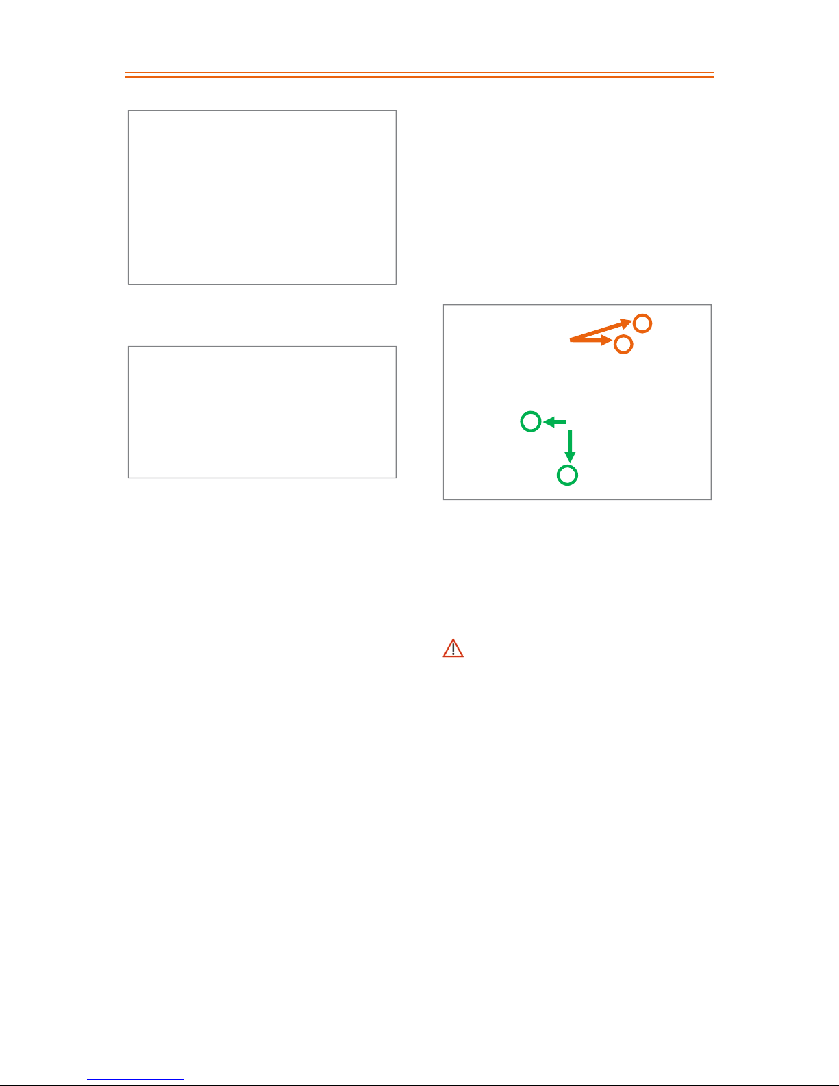
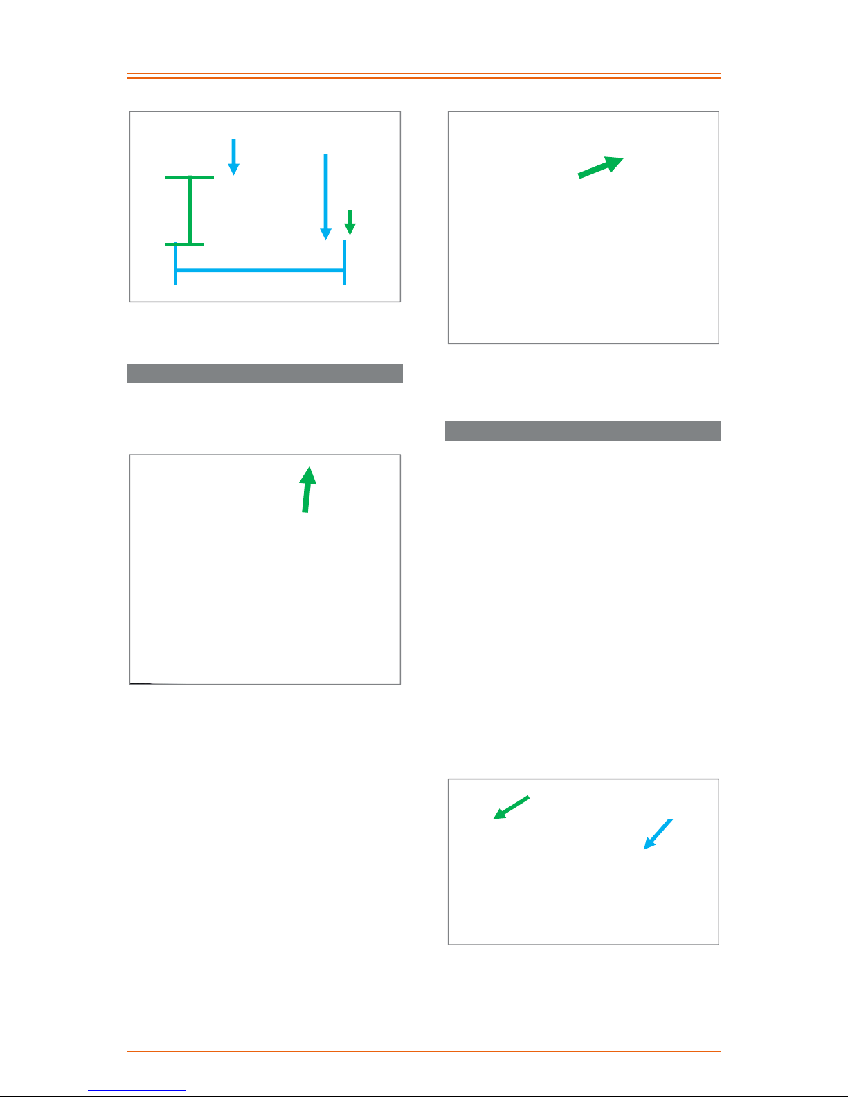
33 Appendix: Avoiding crossed gears with the chain shift
Example with 9-speed cassette:
from the middle
chain wheel, you
can switch to all 9
sprockets
from the large
chain wheel, you
can switch to the
small sprockets
(1-7)
from the large
chain wheel, you
should
not switch
to the large
sprockets (8+9)
=
crossed gear
from the small
chain wheel, you
can switch to the
larger sprockets
(9-3)
from the small
chain wheel, you
should
not switch
to the smallest
sprockets (1+2)
=
crossed gear
Page 29

Operating instruction RAPTOR 4all & 4you
28
34 Appendix: Tightening torques, securing details and tools
The following table shows the torques for shaft screws with a metric control thread (valid if the drawing
or assembly instructions do not state different values!):
Dimension
Torque MA in Nm depending on how tight the screws are
Stability 8.8 Stability 10.9
M4 2.1 3.1
M5 4.2 6.1
M6 7.3 11
M8 17 26
M10 34 51
M12 59 87
M10 x 1 36 53
Securing details: All screws on PRO ACTIV products should be secured with thread lock fluid "medium
strength" (e.g., Weicon AN302-42), where there are no securing clamps on the screw connections
present or there is a lubrication requirement with grease or copper paste.
In the following table you will find tools and care products for your PRO ACTIV product:
Tool Order number
Special tool for setting the wheel position
Open-ended spanner AF 22/24 mm + 41 mm
8000 900 025
Care kit for PRO ACTIV wheelchairs and handbikes
Assembly paste (dosing spray 10 g), Neoval oil (spray 100 ml),
Thread lock fluid, medium strength (Pen-System 10 ml),
Surface cleaner (spray 150 ml), terminal grease (tube 50 ml)
8000 900 026
Page 30

Operating instruction RAPTOR 4all & 4you
29
35 Appendix: Medical product passport / record of training
Product specifications:
Serial number:
Customer data:
Surname, forename:
Street:
Postcode, city:
Phone:
Paying organisation:
Training carried out by:
Medical supplies dealer
PRO ACTIV field
representative
Record of training
I was / we were instructed in accordance with the associated hand-over certificate about the operation
of the product listed and informed about possible operator errors. I was / we were also advised about
situations where the assistance of another person is required. The operating instructions were handed
to me / us.
Instructor
Name, date, signature
1. Person being trained
Name, date, signature
2. Person being trained
Name, date, signature
3. Person being trained
Name, date, signature
For minors, or persons who are not responsible for their actions, legal guardians / supervisors / responsible persons are to be
trained in the use, this is confirmed by their signature. The data is recorded in the feedback system of PRO ACTIV RehaTechnik GmbH, as the manufacturer of the above named product. It will be managed in accordance with Section 16 BDSG
(Federal Data Protection Law).
Stamp / Date / Dealer's signature
Page 31

Operating instruction RAPTOR 4all & 4you
30
36 Appendix: Hand-over certificate
36.1 Required compliance criteria to authorise use
Topics
Completed /
fulfilled
Remarks
The product is suitable for the customer based on
their own judgement and the customer
information received regarding the disabilityrelated restrictions.
The use intended by the customer is fully
consistent with the intended use as described in
the operating instructions (see the Product
description / intended use chapter).
The product's equipment is suitable to allow the
customer safe use with maximum reduction of
risks (see check list on the following page).
The customer was informed about the current /
applicable regulations in accordance with the
road traffic regulations.
The customer's driving ability was checked during
a test drive in difficult driving situations and found
to be appropriate (see the check list on the
following page).
The user, according to their own statements, or
those of the legal representative or guardian and
the assessment of the person providing the
training, is able to meet the requirements of
public traffic in full and to act accordingly. This
ability to act, which is the basis for reducing the
risk for the user and other road users to an
acceptable level, is also completely achievable
taking current illnesses / disabilities into full
account.
The operating instructions, and explicitly all of the
warning and safety instructions contained therein,
were discussed during the training in detail and
understood by the user. The user was then
handed these operating instructions.
Page 32

Operating instruction RAPTOR 4all & 4you
31
36.2 Check list for training the user
Topics
Completed /
fulfilled
Advised of the applicable legal regulations when driving on public roads.
All mechanical function controls were explained and their function demonstrated.
Adaptation and uncoupling the drive unit to / from the chassis was demonstrated and then
performed by the user themselves and / or their assistant.
Operating the parking brake was demonstrated and then performed by the user themselves
and / or their assistant.
Use of the service brakes was demonstrated and then performed by the user themselves
and / or their assistant.
The operation and function of the gears was demonstrated and then performed by the user
themselves and / or their assistant.
The operation of the lights – if fitted – was demonstrated and then performed by the user
themselves and / or their assistant.
Adjustment of the backrest, the seating system and the neck rest was demonstrated and then
performed by the user themselves and / or their assistant.
Removal and installation of the collision guard – if fitted – was demonstrated and then
performed by the user themselves and / or their assistant.
Removal and installation of the running wheels was demonstrated and then tested by the
user themselves and / or their assistant.
Removal and installation of the axle tube was demonstrated and then tested by the user
themselves and / or their assistant.
Test drive: Forwards and, if required, backwards travel through 4 cones spaced at 1.5 m or
2 m
Test drive: Driving on the level, uphill and downhill in the direction of travel
Test drive: Emergency stop from high driving speed
Information for care, cleaning and maintenance of the product have been provided and
understood by the user and / or assistant.
Information on the wheels with regard to inflation pressure and tread depth and checking the
quick release axles have been provided and understood by the user and / or assistant.
Information on regular checks of the brakes have been provided and understood by the user
and / or assistant.
Information on checking the gears including cables and lines and the main tenance of the
chain have been provided and understood by the user and / or assistant.
The contents of the operating instructions from PRO ACTIV and the other component
manufacturers were completely worked through based on the product training and were
understood by the user and / or assistant.
The use of the product is only permitted when all topics listed in "Required compliance criteria for
those permitted to use" have been met by the user and all the points have been ticked off in the
"Check list for training the user".
Page 33

Operating instruction RAPTOR 4all & 4you
32
37 Appendix: Inspection lists
Initial inspection: After 200
km or 5 months
Kilometre reading:___________________
OK /
carried out
not OK resolved
Check all screws / fastening elements are firmly seated
Functional and safety check of all lights (if fitted), steering
and adaptation of the drive unit to the chassis
Functional and safety check of the brakes and, where
necessary, replacement of the brake fluid, brake pads,
brake cables and tyres on the product.
Check, adjust / set, clean and oil the gear components
Check the spoke tension of the drive wheel and, if required,
correct the tension / re-centring
resolved = the fault was corrected
Comments:
Stamp:
Date / Signature
Page 34

Operating instruction RAPTOR 4all & 4you
33
Subsequent inspection: After a further 1000 km or 1 year after the last inspection or after heavy
use
Kilometre reading:___________________
OK /
carried out
not OK resolved
Check all screws / fastening elements are firmly seated
Clean and oil / grease all pivot points and bearings
Visual inspection of the frame and attachments for crack
formation, deformation, etc.
Functional and safety check of the brakes and, where
necessary, replacement of the brake fluid, brake pads,
brake cables
Check, adjust / set, clean and oil the gear components
Check the spoke tension of the drive wheel and, if required,
correct the tension / re-centring
Functional and safety check of the running wheels and
drive wheel, where necessary, replacement of the tyre on
the product
Check the wheel track of the running wheels and that the
drive wheel bearings are firmly seated (tightening torque
70 Nm)
Functional and safety check of the back and seating
system including neck rest (if fitted)
Functional and safety check of the leg rest
Functional and safety check of all lights (if fitted), steering
and adaptation of the drive unit to the chassis
Test drive / functional test
resolved = the fault was corrected
Comments:
Stamp:
Date / Signature
Page 35

Operating instruction RAPTOR 4all & 4you
34
Subsequent inspection: After a further 1000 km or 1 year after the last inspection or after heavy
use
Kilometre reading:___________________
OK /
carried out
not OK resolved
Check all screws / fastening elements are firmly seated
Clean and oil / grease all pivot points and bearings
Visual inspection of the frame and attachments for crack
formation, deformation, etc.
Functional and safety check of the brakes and, where
necessary, replacement of the brake fluid, brake pads,
brake cables
Check, adjust / set, clean and oil the gear components
Check the spoke tension of the drive wheel and, if required,
correct the tension / re-centring
Functional and safety check of the running wheels and
drive wheel, where necessary, replacement of the tyre on
the product
Check the wheel track of the running wheels and that the
drive wheel bearings are firmly seated (tightening torque
70 Nm)
Functional and safety check of the back and seating
system including neck rest (if fitted)
Functional and safety check of the leg rest
Functional and safety check of all lights (if fitted), steering
and adaptation of the drive unit to the chassis
Test drive / functional test
resolved = the fault was corrected
Comments:
Stamp:
Date / Signature
Page 36

Operating instruction RAPTOR 4all & 4you
35
Subsequent inspection: After a further 1000 km or 1 year after the last inspection or after heavy
use
Kilometre reading:___________________
OK /
carried out
not OK resolved
Check all screws / fastening elements are firmly seated
Clean and oil / grease all pivot points and bearings
Visual inspection of the frame and attachments for crack
formation, deformation, etc.
Functional and safety check of the brakes and, where
necessary, replacement of the brake fluid, brake pads,
brake cables
Check, adjust / set, clean and oil the gear components
Check the spoke tension of the drive wheel and, if required,
correct the tension / re-centring
Functional and safety check of the running wheels and
drive wheel, where necessary, replacement of the tyre on
the product
Check the wheel track of the running wheels and that the
drive wheel bearings are firmly seated (tightening torque
70 Nm)
Functional and safety check of the back and seating
system including neck rest (if fitted)
Functional and safety check of the leg rest
Functional and safety check of all lights (if fitted), steering
and adaptation of the drive unit to the chassis
Test drive / functional test
resolved = the fault was corrected
Comments:
Stamp:
Date / Signature
Page 37

Operating instruction RAPTOR 4all & 4you
36
Subsequent inspection: After a further 1000 km or 1 year after the last inspection or after heavy
use
Kilometre reading:___________________
OK /
carried out
not OK resolved
Check all screws / fastening elements are firmly seated
Clean and oil / grease all pivot points and bearings
Visual inspection of the frame and attachments for crack
formation, deformation, etc.
Functional and safety check of the brakes and, where
necessary, replacement of the brake fluid, brake pads,
brake cables
Check, adjust / set, clean and oil the gear components
Check the spoke tension of the drive wheel and, if required,
correct the tension / re-centring
Functional and safety check of the running wheels and
drive wheel, where necessary, replacement of the tyre on
the product
Check the wheel track of the running wheels and that the
drive wheel bearings are firmly seated (tightening torque
70 Nm)
Functional and safety check of the back and seating
system including neck rest (if fitted)
Functional and safety check of the leg rest
Functional and safety check of all lights (if fitted), steering
and adaptation of the drive unit to the chassis
Test drive / functional test
resolved = the fault was corrected
Comments:
Stamp:
Date / Signature
Page 38

Operating instruction RAPTOR 4all & 4you
37
Subsequent inspection: After a further 1000 km or 1 year after the last inspection or after heavy
use
Kilometre reading:___________________
OK /
carried out
not OK resolved
Check all screws / fastening elements are firmly seated
Clean and oil / grease all pivot points and bearings
Visual inspection of the frame and attachments for crack
formation, deformation, etc.
Functional and safety check of the brakes and, where
necessary, replacement of the brake fluid, brake pads,
brake cables
Check, adjust / set, clean and oil the gear components
Check the spoke tension of the drive wheel and, if required,
correct the tension / re-centring
Functional and safety check of the running wheels and
drive wheel, where necessary, replacement of the tyre on
the product
Check the wheel track of the running wheels and that the
drive wheel bearings are firmly seated (tightening torque
70 Nm)
Functional and safety check of the back and seating
system including neck rest (if fitted)
Functional and safety check of the leg rest
Functional and safety check of all lights (if fitted), steering
and adaptation of the drive unit to the chassis
Test drive / functional test
resolved = the fault was corrected
Comments:
Stamp:
Date / Signature
Page 39

Operating instruction RAPTOR 4all & 4you
38
Subsequent inspection: After a further 1000 km or 1 year after the last inspection or after heavy
use
Kilometre reading:___________________
OK /
carried out
not OK resolved
Check all screws / fastening elements are firmly seated
Clean and oil / grease all pivot points and bearings
Visual inspection of the frame and attachments for crack
formation, deformation, etc.
Functional and safety check of the brakes and, where
necessary, replacement of the brake fluid, brake pads,
brake cables
Check, adjust / set, clean and oil the gear components
Check the spoke tension of the drive wheel and, if required,
correct the tension / re-centring
Functional and safety check of the running wheels and
drive wheel, where necessary, replacement of the tyre on
the product
Check the wheel track of the running wheels and that the
drive wheel bearings are firmly seated (tightening torque
70 Nm)
Functional and safety check of the back and seating
system including neck rest (if fitted)
Functional and safety check of the leg rest
Functional and safety check of all lights (if fitted), steering
and adaptation of the drive unit to the chassis
Test drive / functional test
resolved = the fault was corrected
Comments:
Stamp:
Date / Signature
Page 40

Operating instruction RAPTOR 4all & 4you
39
Subsequent inspection: After a further 1000 km or 1 year after the last inspection or after heavy
use
Kilometre reading:___________________
OK /
carried out
not OK resolved
Check all screws / fastening elements are firmly seated
Clean and oil / grease all pivot points and bearings
Visual inspection of the frame and attachments for crack
formation, deformation, etc.
Functional and safety check of the brakes and, where
necessary, replacement of the brake fluid, brake pads,
brake cables
Check, adjust / set, clean and oil the gear components
Check the spoke tension of the drive wheel and, if required,
correct the tension / re-centring
Functional and safety check of the running wheels and
drive wheel, where necessary, replacement of the tyre on
the product
Check the wheel track of the running wheels and that the
drive wheel bearings are firmly seated (tightening torque
70 Nm)
Functional and safety check of the back and seating
system including neck rest (if fitted)
Functional and safety check of the leg rest
Functional and safety check of all lights (if fitted), steering
and adaptation of the drive unit to the chassis
Test drive / functional test
resolved = the fault was corrected
Comments:
Stamp:
Date / Signature
Page 41

Operating instruction RAPTOR 4all & 4you
40
Subsequent inspection: After a further 1000 km or 1 year after the last inspection or after heavy
use
Kilometre reading:___________________
OK /
carried out
not OK resolved
Check all screws / fastening elements are firmly seated
Clean and oil / grease all pivot points and bearings
Visual inspection of the frame and attachments for crack
formation, deformation, etc.
Functional and safety check of the brakes and, where
necessary, replacement of the brake fluid, brake pads,
brake cables
Check, adjust / set, clean and oil the gear components
Check the spoke tension of the drive wheel and, if required,
correct the tension / re-centring
Functional and safety check of the running wheels and
drive wheel, where necessary, replacement of the tyre on
the product
Check the wheel track of the running wheels and that the
drive wheel bearings are firmly seated (tightening torque
70 Nm)
Functional and safety check of the back and seating
system including neck rest (if fitted)
Functional and safety check of the leg rest
Functional and safety check of all lights (if fitted), steering
and adaptation of the drive unit to the chassis
Test drive / functional test
resolved = the fault was corrected
Comments:
Stamp:
Date / Signature
Page 42

Operating instruction RAPTOR 4all & 4you
41
Subsequent inspection: After a further 1000 km or 1 year after the last inspection or after heavy
use
Kilometre reading:___________________
OK /
carried out
not OK resolved
Check all screws / fastening elements are firmly seated
Clean and oil / grease all pivot points and bearings
Visual inspection of the frame and attachments for crack
formation, deformation, etc.
Functional and safety check of the brakes and, where
necessary, replacement of the brake fluid, brake pads,
brake cables
Check, adjust / set, clean and oil the gear components
Check the spoke tension of the drive wheel and, if required,
correct the tension / re-centring
Functional and safety check of the running wheels and
drive wheel, where necessary, replacement of the tyre on
the product
Check the wheel track of the running wheels and that the
drive wheel bearings are firmly seated (tightening torque
70 Nm)
Functional and safety check of the back and seating
system including neck rest (if fitted)
Functional and safety check of the leg rest
Functional and safety check of all lights (if fitted), steering
and adaptation of the drive unit to the chassis
Test drive / functional test
resolved = the fault was corrected
Comments:
Stamp:
Date / Signature
Page 43

Operating instruction RAPTOR 4all & 4you
42
Subsequent inspection: After a further 1000 km or 1 year after the last inspection or after heavy
use
Kilometre reading:___________________
OK /
carried out
not OK resolved
Check all screws / fastening elements are firmly seated
Clean and oil / grease all pivot points and bearings
Visual inspection of the frame and attachments for crack
formation, deformation, etc.
Functional and safety check of the brakes and, where
necessary, replacement of the brake fluid, brake pads,
brake cables
Check, adjust / set, clean and oil the gear components
Check the spoke tension of the drive wheel and, if required,
correct the tension / re-centring
Functional and safety check of the running wheels and
drive wheel, where necessary, replacement of the tyre on
the product
Check the wheel track of the running wheels and that the
drive wheel bearings are firmly seated (tightening torque
70 Nm)
Functional and safety check of the back and seating
system including neck rest (if fitted)
Functional and safety check of the leg rest
Functional and safety check of all lights (if fitted), steering
and adaptation of the drive unit to the chassis
Test drive / functional test
resolved = the fault was corrected
Comments:
Stamp:
Date / Signature
Page 44

Operating instruction RAPTOR 4all & 4you
43
Your specialist dealer:
PRO ACTIV Reha-Technik GmbH
Im Hofstätt 11
72359 Dotternhausen – Germany
Tel. +49 7427 9480-0
Fax +49 7427 9480-7025
E-Mail: info@proactiv-gmbh.de
www.proactiv-gmbh.com
No. 000 000 1533
© 11/2014 PRO ACTIV Reha-Technik GmbH. All rights reserved.
in accordance with Directive 93/42/EEC for medical products
 Loading...