

Page 1
Operating Instructions
LIFT
Wheelchair with
adjustable seat height
subject to EC Directive 93/42/EWG for Medical Devices Printed in Germany 07/2010
Page 2

Page 3

Contents
1. Scope of delivery .......................................1
1.1 Before initial use ....................................2
2. Product description .....................................2
2.1 Lifting mechanism .................................3
2.1.1 Wheelchair with mechanical lifting mechanism ........... 4
2.1.2 Wheelchair with electrical lifting mechanism ............. 4
3. Specific requirements ...................................4
3.1 Angle of backrest ..................................4
3.2 Sag of seat and backrest covering .................... 5
3.2.1 Body Contour..................................... 5
3.2.2 Adjustable seat and backrest covering .................5
3.3 Seat angle / seat height at front ......................5
4. Tipping and turning stability ...............................6
4.1 Positioning drive wheels ............................ 6
4.2 Wheel camber ....................................6
4.3 Positioning castors................................. 6
5. Anti-tip support......................................... 7
6. Maintenance and care ...................................8
6.1 Adjusting toggle joint brake ..........................8
6.2 Adjusting castor axle ...............................8
6.3 Choosing appropriate castor .........................9
6.3.1 „Wobbling“ castors .................................9
6.4 Checking and adjusting wheel track ...................9
6.5 Checking bolted joints .............................10
6.6 Tire pressure ....................................10
6.7 Care of quick-release axles and ball bearings ..........10
6.8 Cleaning the wheelchair ...........................10
6.9 Protection against corrosion ........................10
7. Safety instructions .....................................11
8. Warranty ............................................13
Page 4

1
Dear Customer,
We congratulate you on the purchase of
your PRO ACTIV wheelchair.
With this wheelchair, you have purchased
a quality product that is tailored specially to
meet your needs.
The following information contains details
on how to use your wheelchair. Read
these instructions carefully before using
your wheelchair.
Should you have any questions regarding
your new wheelchair, please do not hesitate
to contact us.
Your PRO ACTIV team.
PRO ACTIV
Reha-Technik GmbH
Im Hofstätt 11
D-72359 Dotternhausen
Tel. 0 74 27/ 94 80-0
Fax 0 74 27/ 94 80-25
info@proactiv-gmbh.de
www.proactiv-gmbh.de
1. SCOPE OF DELIVERY
The PRO ACTIV wheelchair is equipped
with backrest and seat covering, drive
wheels, castors, footrest and two anti-tip
supports.
In accordance with your order, the wheelchair is equipped with additional accessories, e.g. folding backrest, V-shape, handgrips, castor fork with quick tighten/release
mechanism, seatbelt.
Please check that your wheelchair is complete upon receipt!
The wheelchair is tested and fully mounted
before leaving the factory. However, to ensure safe transport, some parts are packed
separately.
The lifting movement is secured by a restraining belt that is fed under the parallelogram arm and the cross tube of the frame.
Remove the restraining belt before using
the wheelchair. Keep the restraining belt in
place for transporting purposes.
The wheelchair is tested for complete functionality before delivery. Should you wheelchair become damaged during transport,
please contact your medical supplies dealer
or PRO ACTIV immediately.
Page 5
2
1.1 BEFORE INITIAL USE
nFold up the armrests. The armrest locks
into position when both indexing bolts
are activated
nMount the anti-tip supports on both sides
so that the wheelchair can only tilt slightly and the castors are raised max. 13 cm
from the floor. Use the retention holes in
the tubes of the anti-tip supports to vary
the tilting height. Secure the anti-tip support in the corresponding hole using the
quickpin
n Remove the restraining belt from the lift-
ing mechanism
It is important that both you, your attendant
care staff or your escorting person are familiar with and observe these operating instructions and the warnings that are contained in
them.
Disregarding warnings can result in damage
to the wheelchair, in falling, tipping or loss of
control over the wheelchair/situation. This
can lead to the wheelchair driver or other
persons suffering severe injuries.
Your therapist/doctors should inform you,
your attendant care staff/escorting persons
of the movements you are capable of performing with the wheelchair before initial
use. They should also explain which wheelchair techniques you are capable of learning
with your handicap. Do not undertake manoeuvres with the wheelchair that you have
not practised or are capable of.
Your therapists/doctors and medical supplies
dealer should also instruct you and your attendant care staff/escorting persons in how
to use your wheelchair and the settings as
well as the safety accessories (e.g. anti-tip
supports, seatbelt) that are available. These
instructions must be complied with.
Do not overestimate your own ability or underestimate dangerous situations/manoeuvres with the wheelchair as this may have
serious consequences for you and other
persons.
2. PRODUCT DESCRIPTION
The PRO ACTIV LIFT is a wheelchair with
a seat that can be adjusted 30 cm in height.
The numerous adjustment possibilities enable the driver of the wheelchair to adapt it
to his/her specific requirements. The lifting
mechanism is available either as an electrical or mechanical version.
The frame, the lifting mechanism and other
parts are manufactured from high resistance
aluminium alloy. Depending on the accessories and the wheelchair dimensions, the
overall min. weight is 19 kg (mechanical version) or min. 35 kg (electrical version).
Wheelchairs with folding backrest: The angle of the folding backrest of the wheelchair
can be set at 7 different positions. The sag
of the seat and backrest covering can be
adjusted to the requirements of the user
with Velcro ribbons (not possible with Body
Contour version). The adjustable backrest
ensures comfortable seating and a good sitting posture that avoids strain on the spinal
column.
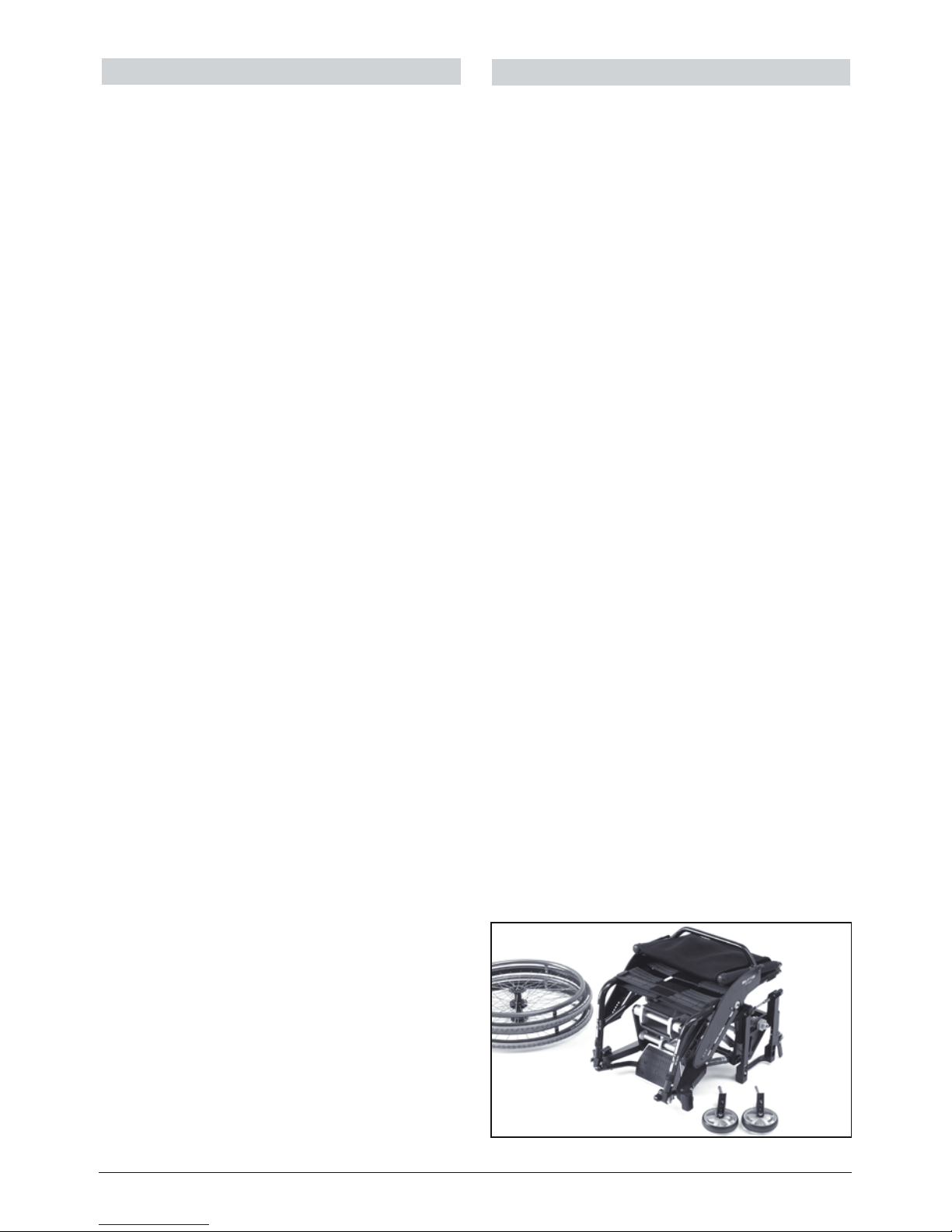
Wheelchair with folding backrest and quickrelease castor axles. The backrest of these
versions can be folded down onto the seat,
the armrests folded down at the side and the
castor forks with castors as well as the drive
wheels can be removed for loading/transport purposes.
Fig. 1
Page 6

3
IMPORTANT
Ensure before mounting/using the wheelchair, that the backrest is securely fixed in
the desired position and the armrests locked
in position. The quick-release axles of the
castors and drive wheels must also be securely locked in position (actuation button in
initial back position, groove visible).
2.1 Lifting mechanism
IMPORTANT
The wheelchair is supplied with a lifting
mechanism that is adapted to the weight
of the user. For this reason, the wheelchair
may only be used by this person. Persons
of a different weight using the LIFT influence the lifting and lowering behaviour of
the wheelchair. Do not exceed the max.
loading capacity of 100 kg.
IMPORTANT
Do not open and heat the gas strut. For
service or repair work, contact your medical
supplies dealer or PRO ACTIV.
IMPORTANT
Before activating the lifting mechanism of
the wheelchair, ensure that it is standing on
even ground. Apply the brake and mount
the anti-tip support.
IMPORTANT
Neither the user nor any other person
should move the wheelchair when the seat
is raised.
IMPORTANT
When raising/lowering the seat or when the
seat is already raised, observe the following
points:
nDo not lean backward, forward or to the
side beyond the seat of the wheelchair
nThe additional load supported by the
user should not exceed 10% of their
body weight. The additional load should
only be picked up or deposited from the
front (not side) in an upright sitting posi-
tion. Support the load on the thighs during the lifting movement
nDuring the lifting and lowering move-
ment, clasp the centre of the armrest
with both hands. Do not bend back the
thumbs
nNeither the user nor the accompanying
person should touch the mechanical
components of the wheelchair underneath the seat
IMPORTANT
The wheelchair should only be exposed
to environmental temperatures of -25 and
50°C, i.e. do not use the wheelchair in
freezer rooms, environmental simulation
chambers, etc. or in the sauna. Do not use
or park the wheelchair near fires or other
sources of heat if there is a risk of this temperature being exceeded.
IMPORTANT
The wheelchair must stand on horizontal,
level and solid ground. All four wheels must
stand securely on the ground, i.e. not on
thresholds or surfaces that are at different
levels, etc.
The wheel grip should not be impeded by
moisture, snow, ice, cleaning agents, lubricants, fuel etc.
Do not use the wheelchair in water or on
sandy, rough surfaces.
IMPORTANT
Do not use the wheelchair for mounting
stairs and thresholds exceeding 30 cm in
height.
Page 7

4
2.1.1 Wheelchair with mechanical lifting
mechanism
To adjust the seat, proceed as follows:
nRelease the brake (Fig. 2 a)
nClasp the wings of the armrests (Fig. 2
b) in the middle with both hands. Do not
bend the thumbs backward
nPull the lever of the triggering mecha-
nism (Fig. 2 c) upwards, (this lever is
mounted at the right underneath the
armrest)
nPush yourself upward or downward
when activating the lever
nRelease the lever of the triggering
mechanism (Fig. 2 c), and the wheelchair
stops at the desired height
2.2.1 Wheelchair with electrical lifting
mechanism
To adjust the seat, proceed as follows:
nRelease the brake
nActivate the control knob (red raise,
green lower) to move the seat upward/
downward
nAs soon as you let go of the control
knob, the wheelchair remains at the
desired height
3. SPECIFIC REQUIREMENTS
3.1 Angle of backrest
If the wheelchair is equipped with a backrest with angle adjustment, the backrest
can be adjusted to 7 different positions in
5° increments.
If possible, we recommend setting the
backrest upright to obtain a comfortable
sitting position. Low backrests for handicapped persons - We recommend tipping
the backrest slightly forward and loosening
the top belt of the backrest covering (not
possible Body Contour version) so that the
sag is greater at the top.
Bitte beachten Sie, dass der Verstellbereich
der Rückenlehne bei der Auslieferung ab
Please note that the adjustment mechanism of the backrest is secured by a stop
screw (Fig. 3 c) before leaving the factory.
The stop screw allows the backrest to be
tilted max. 7° backward from the vertical
position. Remove the stop screw to use the
entire adjustment range of the backrest.
The stop screws can also be used as a
position stop so that you do not have to
search for your own special backrest position when mounting the wheelchair.
IMPORTANT
Removing the stop screw may increase
the risk of tipping. To counteract this, the
changing of anti-tipping adjustment might
be necessary.
To adjust the backrest, remove any pressure (otherwise risk of tipping) and release
the drop-in pins (Fig. 3 a) that drop into the
b
a c
Fig. 3
a
c
b
Fig. 2
Page 8

5
holes on the left and right side. To do this,
pull the middle of the cord (Fig. 3 b) located
underneath the seat covering that is connected to the drop-in pins.
After releasing both drop-in pins, the backrest can be adjusted as desired. Release
the cord to lock the backrest in position
again. Ensure that both drop-in pins are
securely fixed in the desired holes before
using the backrest.
Should the seat angle be changed, the
backrest can be re-adjusted accordingly at
any time.
When driving up inclines and transporting
luggage (e.g. rucksacks) on the backrest,
the centre of gravity is shifted to the back.
This can be compensated for by tipping
the backrest forward so that the wheelchair
does not tip backward as easily.
For comfortable sitting, the backrest can be
fixed in the last position so that it is tilted
slightly backward.
IMPORTANT
Tilting the backrest backward shifts the centre of gravity. The further back the backrest
is tilted, the sooner the point of tipping in
this direction is reached.
3.2 Sag of seat and backrest covering
The wheelchair is equipped according to
the order with the seat and backrest covering „Body Contour“ or with an adjustable
seat and backrest covering. Both types of
covering ensure excellent air circulation
which can be advantageous when used
in conjunction with a suitable cushion for
problems caused by decubitus.
3.2.1 Body Contour
The seat and backrest covering of the Body
Contour version can considerably improve
the driving comfort due to its elasticity and
in conjunction with a suitable cushion can
help to prevent decubitus. However, the
Body Contour covering cannot be adapted
to the special needs of each individual.
3.2.2 Adjustable seat and backrest covering
The adjustable seat covering comprises a
belting system. The horizontal belts can be
pulled taut by Velcro fasteners so that the
seat sag can be adjusted accordingly.
Fig. 4
a
The backrest also comprises a belting
system. The sag of the backrest can be
adapted to the special requirements of each
individual. Remove the backrest cushion
and adjust the horizontal belts at the buckle
(Fig. 4 a) as required. To prevent the buckle
bar from bending, feed both belts through
the buckle. Replace the backrest cushion.
IMPORTANT
Check the tautness of the seat and backrest covering at regular intervals and in
case of doubt, allow the medical supplies
dealer to check its state. A tear in the seat
or backrest covering may cause accidents
with severe injuries.
Always sit down in the wheelchair slowly
to prevent the seat and backrest covering
from tearing.
3.3 Seat angle / seat height at front
Once the seat height at the back is set
as required, the seat angle and the seat
height at the front can be set accordingly.
Numerous castors and 3 different castor
forks (Fig. 5) are available for this purpose:
1-slot, 2-slot and 3-slot forks. The matching
forks are installed at the factory according to your seat height/length of lower leg.
Page 9

6
Three positions are available for mounting
the castors.
In order to increase the angle of the seat,
mount the castors at a lower position. If
the castors are mounted at a higher position, the angle of the seat is reduced. If
the adjustment range of the fork does not
suffice, choose the next longer or shorter
one as required. The bottom position of the
1-slot fork is equivalent to the top position of
the 2-slot fork and the bottom position of the
2-slot fork is equivalent to the top position of
the 3-slot fork.
IMPORTANT
After altering the angle of the seat, check
the wheel track and reset if necessary. Also
readjust the castor axle and the brakes
accordingly (see 6.1-6.2 and 6.4). Ensure that
there is sufficient space between the footrest and the floor. This should not be less
than 4 cm.
4. TIPPING AND TURNING STABILITY
Easy tipping and turning stability of the
wheelchair can be achieved when the axle
mount of the drive wheels is located near to
the centre of gravity of the wheelchair user.
Moving the drive wheels further back reduces the risk of the wheelchair tipping but also
makes it more difcult to turn and steer. Settings, however, should be made according
to the requirements/ability of each individual
to ensure safe driving.
4.1 Positioning drive wheels
Remove the drive wheels from the quick-release axles.
Loosen the xing nut (Fig. 10 a) with a SW
41 screwdriver, push the socket (Fig. 10 b)
along the slot and tighten the nut again with
a torque of 75 Nm.
Ensure that the sockets on the left and right
are at the same position on the wheel holder.
IMPORTANT
After shifting the axle mount for the drive
wheels, check the wheel track and readjust
if necessary (see 6.4). Also readjust the castor axle and the brakes accordingly (see 6.1.-
6.2).
IMPORTANT
Extreme settings, for example, drive wheels
that are mounted much further forward are
only permitted for practised drivers who can
shift their weight forward when driving. Antitip supports are compulsory.
4.2 Wheel camber
The negative wheel camber is in accordance with your order.
A wheel camber not only increases the
stand stability at the side of your wheelchair
but also widens the track (overall width) of
the wheelchair.
4.3 Positioning castors
The castor fork can be mounted at two positions.
Fig. 5
Page 10

7
IMPORTANT
After altering the distance between the castor and the drive wheel, re-adjust the castor
axles (see 6.2).
5. ANTI-TIP SUPPORT
In order to reduce the risk of unintentionally
tipping the wheelchair backward to a minimum, the wheelchair is equipped with two
anti-tip supports.
To negotiate an obstacle, remove the locking bolts (quickpins) (Fig. 6 a). and take off
the anti-tip supports so that they do not
make contact with the ground.
After overcoming the obstacle, replace the
anti-tip supports in the correct manner (see
1.1)
IMPORTANT
The anti-tip support is designed exclusively
to minimize the risk of the wheelchair tipping backward. It is not intended to reduce
the risk of the wheelchair tipping forward or
to the side. There are no safety accessories
to minimise these risks. We therefore, recommend that your therapists and doctors
instruct you how to cope with these risks.
IMPORTANT
Before using the wheelchair, anti-tip supports and after making any adjustments
to the wheelchair, ensure that the anti-tip
supports function correctly. Ensure that
they are securely mounted in their brackets
and fixed with the locking bolts (quickpins)
(see 1.1).
Check that the anti-tip supports function
correctly after use and at regular intervals.
Should the anti-tip supports no longer function, or you are in doubt as to whether they
are functioning correctly, allow your medical
supplies dealer to check and repair them if
necessary before further use. Otherwise
there is a risk of falling and injury.
Fig. 6
a
Page 11

8
released, the brake bolt should not rub
on the wheel
The force of the brake lever can be adjusted
using the adjusting screws (Fig. 7 d). Use a
screwdriver and an SW 8 mm spanner. Oil
the joints of the brake at regular intervals.
IMPORTANT
In its standard setting, the brake bolt is
mounted in position (Fig. 7 e). It may be necessary to mount the brake bolt in position
(Fig. 7 f) after adjusting the drive wheels.
Please contact your medical supplies dealer or PRO ACTIV for this purpose.
IMPORTANT
Please note that the toggle joint brake of
your wheelchair is a parking brake that
may only be applied when the wheelchair is
stationary. It is not suitable or intended for
reducing speed.
IMPORTANT
Please note that the distance between the
brake bolt and tire of the toggle joint brake
of your wheelchair when correctly set (see
6.1) must be 3 mm to max. 4 mm. Therefore,
only use the hand rims to propel the wheelchair. When propelling the wheelchair with
the tires (thumb or finger on the surface of
the tire) there is a risk of fingers and thumb
becoming squashed between the brake bolt
and the tire.
6.2 Adjusting castor axle
To ensure good steering and directional
stability of your wheelchair, align the castor
axle vertically on even ground (Fig. 8).
The castor axles may require adjusting for
the following reasons:
n You have altered the position of the
drive wheels
n You have altered the height or angle of
the seat
n The castor axles are no longer vertical
due to an accident or impact
6. MAINTENANCE AND CARE
We recommend regular (at least annually)
maintenance and care of the wheelchair by
PRO ACTIV or the medical supplies dealer.
In particular, the wheelchair should be serviced before and after intensive use, e.g.
during summer or winter vacations.
6.1 Adjusting toggle joint brake
It may be necessary to adjust the brake (Fig.
7 a) for several reasons:
n You have altered the tires or the filling
pressure
n You have altered the position of the
drive wheels
n The brake movement is dissimilar after
long use
To adjust the toggle joint brake, proceed as
follows:
1. Loosen the fastening screws (Fig. 7 b)
that fix the brake plate to the armrest
2. Position the released brake so that
there is a distance of 3 mm to max.
4mm between the brake bolt (Fig. 7 c)
and the tire
3. Tighten the fastening screws again
4. Check the correct setting of the brakes.
If the brake is applied, the drive wheels
should not turn when medium-force
pressure is applied. When the brake is
a
b
c
d
f
e
Fig. 7
Page 12

9
n The wheelchair veers to the left or right
when driving on even ground (the cause
may be uneven pressure of the drive
wheels)
To set the castor axles, move the wheelchair onto even ground. Adjust the right
castor fork, then the left one and then check
the right one again. Proceed as follows:
1. Check and correct the wheel track
before re-adjusting the castor axle
2. Loosen the locking screw (Fig. 8 b) (Allen
key SW 2.5 mm and spanner SW 8)
3. Loosen the fastening screws (Fig. 8 c)
(Allen key 5 mm) that fix the clamp
blocks to the frame
4. Move the castor block (Fig. 8 a) into
the vertical position. To do so, check
whether the front edges of the clamp
blocks and thus the castor axles are at a
right angle (90°) to the ground. This can
be checked most simply by using a corresponding triangle. If this setting is not
possible, contact your medical supplies
dealer or PRO ACTIV
5. Tighten the fastening screws again with
a torque of 12 Nm and check the vertical
position
6. Apply locking screw again slightly to the
M6 screw and fix with the SW 8 nut
6.3 Choosing appropriate castor
A variety of castors are available. The
choice of castor depends greatly on the
intended use and driving ability.
Observe the following when mounting and
dismantling the PRO ACTIV aluminium castors:
n An Allen key SW 4 is located in the
centre of the axle to fix the movement
of the aluminium axle for mounting/dismantling
n The tightening torque of the axle fasten-
ing screw M6x16 ISO 7380 is 5 Nm
n Secure the screws with special lacquer!
6.3.1 „Wobbling“ castors
The limit speed at which castors begin to
„wobble“ is reduced when:
n The castor diameter increases
n The weight of the castors increases
n The castor load is reduced
n The after run of the castors is reduced
IMPORTANT
Should the castors begin to wobble, reduce
speed immediately to minimise the risk of
the castors jack-knifing and blocking and
thus avoiding an accident.
6.4 Checking and adjusting wheel track
A good wheel track is essential for the easy
running of the wheelchair. To check the
wheel track, proceed as follows:
Measure the distance (Fig. 9 y) at the front
and back between the drive wheels at the
shaft centre (Fig. 9 x). The distance between
the front and the back of both drive wheels
should be the same. If the distance differs
by more than 5 mm, then the track must
be corrected. Correction is also necessary,
if the distance (Fig. 9 z) is not the same on
both sides.
c
Fig. 8
b
a
y
y
x
z
Fig. 9
Page 13

10
tires of the wheelchair to extremely high
temperatures, e.g. sauna or in glassed in
areas in summer.
6.7 Care of quick-release axles and ball
bearings
Clean and lubricate the quick-release axles
of the drive wheels and castors as well as all
ball bearings at regular intervals to ensure
that they function reliably at all times.
6.8 Cleaning the wheelchair
The wheelchair must be cleaned regularly to prevent parts from becoming stiff
and sluggish. In particular, the wheelchair
should be cleaned thoroughly before and
after intensive use, e.g. during summer or
winter vacations.
Clean your wheelchair with water and spirits. Do not use abrasives to avoid scratching the outer coating. Do not clean the
wheelchair with a high pressure cleaner.
Store the wheelchair in a dry place and if
possible keep it covered.
6.9 Protection against corrosion
In order to avoid malfunction or breakage of
components, do not expose the wheelchair
to aggressive environmental conditions. If
this cannot be avoided, clean the wheelchair immediately after use and lubricate
movable parts. Regular cleaning (see 6.8)
prevents corrosion.
The LIFT wheelchair has just a 1° camber.
Therefore the wheel track deviates just a
minimum when changing the seat angle
(see 3.3). For this reason it is not possible to
adjust the wheel track.
In case the symmetric adjustment to the
frame should be changed (Fig. 10 a), please
proceed as follows:
1. Loosen the aluminium nuts SW 41 (Fig.
10 a) on both sides
2. Ensure that the distance to the frame
(Fig. 9 z) at the right and left is the same
3. Tighten the aluminium nut with a torque
of 70 Nm
b
a
Fig. 10
6.5 Checking bolted joints
Check the tightness of the bolted joints two
and six weeks after delivery of the wheelchair. Check them again at regular intervals
(depending on distances covered and general strain).
6.6 Tire pressure
Check the tire pressure at regular intervals
and after being exposed to extreme temperature conditions. The max. tire pressure
is printed on the outer case of the tire and
should be adhered to.
IMPORTANT
We cannot guarantee correct functioning of
the toggle joint brake if tire pressure is too
low. The risk of punctures also increases.
Increases in temperature increase the tire
pressure. If pressure is too high, the tire
can burst. Therefore, do not expose the
Page 14

11
7. SAFETY INSTRUCTIONS
IMPORTANT
Only use the wheelchair for the intended
purpose.
The intended purpose of a wheelchair is to
enable a disabled person to replace his/her
inability to move by technical means in
the form of a wheelchair. In the figurative
sense, the equivalent of walking is driving a
wheelchair dead slow. This applies in particular when using an auxiliary drive.
Using the wheelchair for purposes other
than those intended can result in damage to
the wheelchair that can lead in turn to accidents or injuries to the wheelchair driver.
IMPORTANT
Should you have difficulties in understanding the operating instructions, please contact your medical supplies dealer or PRO
ACTIV immediately. Understanding the
warnings and explanations in the operating
instructions is imperative not only for safe
but also correct use.
IMPORTANT
If the wheelchair together with user has
to negotiate obstacles, e.g. stairs, and
facilities such as ramps and elevators are
provided for this purpose, then they must
be used. If such facilities are not available,
the obstacle must be negotiated by 2 persons carrying the wheelchair together with
its user. Do not carry the wheelchair at the
sides and with the footrest.
We recommend holding the wheelchair at
the handgrips or the backrest bow and the
frame. Ensure that the handgrips fit correctly and are securely fixed. This also applies
to adjustable (height) handgrips. If this is
not the case, do not lift the wheelchair with
the handgrips.
Before negotiating an obstacle (stairs,
thresholds, etc.) swivel the anti-tip supports
under the frame or remove them completely, so that they do not come into contact
with the stairs, as this can cause serious
accidents. Move the anti-tip supports into
their correct position again.
IMPORTANT
Do not stand on the footrest when getting
into/out of the wheelchair due to risk of
tipping.
IMPORTANT
Transporting the wheelchair driver or other
persons in the wheelchair in vehicles has
not been tested by PRO ACTIV and is
therefore, not approved.
The wheelchair can be equipped with a
support headrest. These support systems
are not approved as neck supports for
transport in vehicles.
The seat belt is not designed as a safety
belt for vehicles and should not be used for
this purpose.
IMPORTANT
The max. permissible load of the wheelchair
is 100 kg. Please ensure that this load limit
is not exceeded when transporting objects
and when performing fitness exercises in
the wheelchair.
IMPORTANT
Please ensure when using equipment from
other manufacturers (e.g. seat cushions,
drive devices, etc.) together with your
wheelchair, that the individual components
are suitable and function in conjunction with
the wheelchair correctly. For information on
the suitability of the components, please
contact the relevant manufacturer, your
medical supplies dealer or PRO ACTIV.
IMPORTANT
The wheelchair has several folding mechanisms (e.g. backrest). It is in the nature of
things, that such mechanisms host certain
risks (e.g. squashing of fingers, etc.). We
endeavour to minimise risks as far as possible by corresponding technical constructions. However, a certain risk still remains.
For this reason, please allow the trained
Page 15

12
Ensure that the seatbelt is not fastened too
tightly otherwise this may have a negative
effect on breathing or cause strangulation
in case of an accident or tipping. The driver
of the wheelchair should always be able to
remove the belt easily.
IMPORTANT
In the interests of your own safety, contact
your medical services dealer or PRO ACTIV
should your wheelchair require repairing
so that damage can be eliminated immediately. To maintain the safety of your wheelchair and its warranty, only use original
parts supplied by the manufacturer. Screws
and other elements of the wheelchair must
be correctly and securely replaced during
repair work.
IMPORTANT
Drive carefully and avoid blocking the castors when driving over potholes and loose
stones.
To negotiate obstacles, e.g. kerbs or steps,
the user will have to move his/her body
weight to assist the manoeuvre, otherwise
the castors may jack-knife and block. This
may result in damage to the castors or the
castor fork and injuries. Do not attempt
to negotiate the obstacle if you cannot
actively assist the manoeuvre. This should
be given special attention when using auxiliary drives.
IMPORTANT
There is a higher risk of tipping backward
when driving backward without the anti-tip
support. Therefore, always use the anti-tip
supports when driving backward. If this
is not possible, assisting persons should
ensure that the wheelchair does not tip
over.
IMPORTANT
Due to the extremely high risk of tipping
and injury, do not attempt to use moving
staircases with the wheelchair.
personnel of your medical supplies dealer
to explain how to handle the wheelchair and
to test its mechanisms under their supervision. PRO ACTIV is also available to assist
you in this respect.
IMPORTANT
Please note that parts of your wheelchair
may become overheated due to extreme
ambient temperatures (e.g. sauna). This
may lead to risks of burning that should not
be underestimated when the wheelchair
is being used by persons suffering from
hyperpathy.
To minimise these risks, take the necessary
measures (e.g. cover heated parts with a
towel or move the wheelchair out of the
heated area when in the sauna.
Certain risks that are also possible during extremely low temperatures can be
minimised by wearing appropriate insulated
clothing.
IMPORTANT
If required, your wheelchair can be equipped
with a seat belt (Fig. 11 a). The belt can
be purchased from your medical supplies
dealer. Secure the belt by wrapping it round
the backrest and fixing it directly to the tube
of the backrest using the fastening screw in
the side panel (Fig. 11 b).
b
a
Fig. 11
Page 16

13
IMPORTANT
Modifications to the wheelchair that have
not been specifically approved by the manufacturer result in the loss of the warranty.
These modifications may result in safety
risks and are therefore prohibited.
IMPORTANT
Ensure that the lights on your wheelchair
function correctly and are clearly visible.
8. Warranty
The warranty conditions can be found in
the enclosed Warranty Agreement and/or
General Terms of Business.
 Loading...