

Page 1
Installation Manual
Pro1 Technologies
1111 S. Glenstone Ave., Suite 2-100
Springeld, MO 65804
Toll Free: 888-776-1427
Web: www.pro1iaq.com
Hours of Operation: M-F 9AM - 6PM Eastern
T855S
Installation Tips
Wall Locations
The thermostat should be installed approximately 4 to 5 feet above the
oor. Select an area with average temperature and good air circulation.
Thermostat Application Guide
Description
Gas or Oil Heat
Electric Furnace
Heat Pump (No Aux. or Emergency Heat)
Heat Pump (With Aux. or Emergency Heat)
Multi-Stage Systems
Heat Only Systems
Cool Only Systems
Millivolt
Wired Remote Sensing
Table of Contents
Page
Installation Tips
Thermostat Quick Reference
Private Label Badge
Wiring
Wiring Diagrams
Technician Setup Menu
Programming
Features
11-12
13-19
20-28
29-30
Specications
Yes
Yes
Yes
Yes
Yes
Yes
Yes
Yes
Yes
2-4
5-7
8
9-10
31
Power Type
Battery Power
Hardwire (Common Wire)
Hardwire (Common Wire) with
Battery Backup
A trained, experienced
technician must install this
product.
Carefully read these
instructions. You could damage
this product or cause a
hazardous condition if you fail
to follow these instructions.
Una version en espanol de este
manual se puede descargar en
la pagina web de la compania.
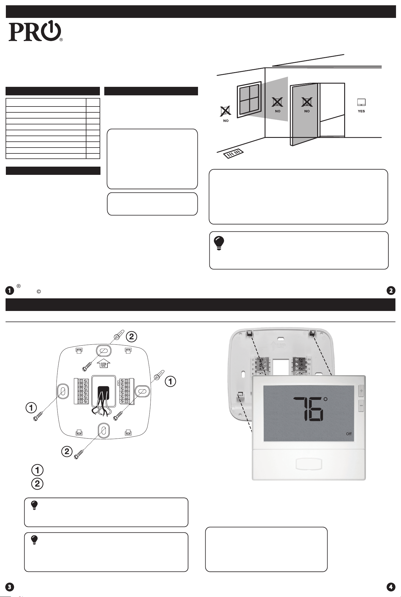
Do not install thermostat in these locations:
• Close to hot or cold air ducts
• That are in direct sunlight
• With an outside wall behind the thermostat
• In areas that do not require conditioning
• Where there are dead spots or drafts (in corners or behind doors)
• Where there might be concealed chimneys or pipes
Installation Tip
Pick an installation location that is easy for the user to access. The temperature
of the location should be representative of the building.
U.S. Registered Trademark. Patents pending
Copyright 2016 All Rights Reserved.
Installation Tips
Subbase Installation
Rev. 1626
Installation Tips
Mount Thermostat
5:23
Menu
Tue
F
Auto
PM
Horizontal Mount
Vertical Mount
Installation Tip: Electrical Hazard
Failure to disconnect the power before beginning to install this product
can cause electrical shock or equipment damage.
For horizontal mount put one screw on
the left and one screw on the right.
For vertical mount put one screw on
the top and one screw on the bottom.
Mercury Notice
All of our products are mercury free. However, if the product you are
replacing contains mercury, dispose of it properly. Your local waste
management authority can give you instructions on recycling and
proper disposal.
Align the 4 tabs on the subbase with
corresponding slots on the back of the
thermostat, then push gently until the
thermostat snaps in place.
Note: To ensure a solid t between the
thermostat and the subbase:
1. Mount subbase to a at wall
2. Use screws provided
3. Drywall anchors should be ush with the wall
4. Wires should be pushed into the wall
Page 2
Thermostat Quick Reference
Thermostat Quick Reference
Battery Installation
Battery installation is recommended even if the thermostat is
hardwired (C terminal connected). When the thermostat is hardwired
and batteries are installed, the thermostat will activate a compressor
delay of 5 minutes when it detects a power outage from the hardwired
power supply.
Important:
High quality alkaline batteries are recommended.
Rechargeable batteries or low quality batteries
do not guarantee a 1-year life span.
To release battery cover press nger bevel
on the left side and lift the cover to access
batteries.
Refer to your Operating Manual
for programming and operation
instructions A copy can be
downloaded at www.pro1iaq.com
Replace AA Batteries when low battery indicator shows in display.
Insert 2 AA Alkaline batteries
(included). High quality alkaline
batteries are recommended.
Select Heat, Off, or Cool as
needed. Select Fan On for
continuous operation or
Auto to cycle fan with system.
Simple operating instructions
are found on the back of the
battery door.
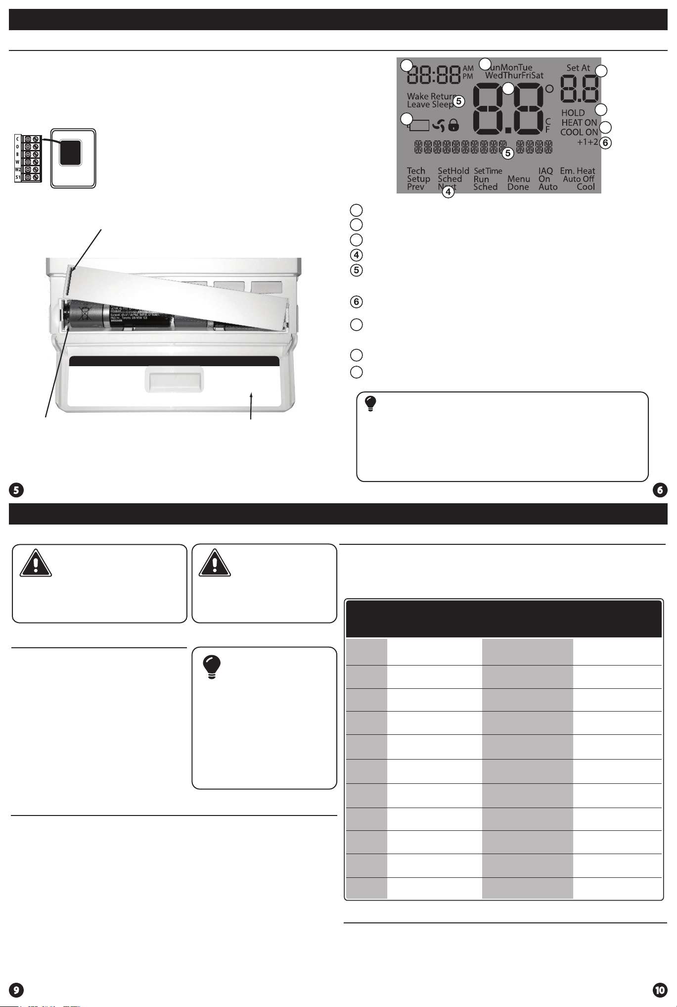
Getting to know your thermostat
2
3
LOW
Indicates the current room temperature
1
Time and day of the week / Outdoor Temperature if R251S is installed.
2
Low Battery Indicator: Replace batteries when this indicator is shown.
3
Program Menu Options: Show dierent options during programming.
Program Time Periods - Residential: Uses 4 time periods - WAKE, RETURN,
LEAVE & SLEEP. Commercial: Uses 2 or 4 time periods that appear in the text
eld - Occupied & Unoccupied.
Staging Indicators: +1 will appear in the display when second stage of
heat or cool is on. +2 will appear for the third stage of heat.
7
System Operation Indicators:
If these or the Fan indicator are ashing, it means that the system is in a
delay of some type (compressor delay, cooling fan delay, staging delay).
Hold: is displayed when the thermostat program is permanently overridden.
8
Setpoint: Displays the user selectable setpoint temperature.
9
2
9
1
8
Important
The low battery indicator is displayed when the AA battery power is low. If the user
fails to replace the battery within 21 days, the screen will only show the low battery
indicator but maintain all functionality. If the user fails to replace the batteries after
an additional 21 days (days 22-42 since rst “low battery” display) the setpoints will
change to 55˚F (Heating) and 85˚F (Cooling). If the user adjusts the setpoint away from
either of these, it will hold for 4 hours then return to either 55˚F or 85˚F. After day 63
the batteries must be replaced immediately to avoid freezing or overheating because
the thermostat will shut the unit o until the batteries are changed.
7
Wiring
Caution:
Electrical Hazard
Failure to disconnect the power
before beginning to install this
product can cause electrical shock
or equipment damage.
Wiring
1.
If you are replacing a thermostat,
make note of the terminal
connections on the thermostat that
is being replaced. In some cases
the wiring connections will not be
color coded. For example, the
green wire may not be connected
to the G terminal.
2.
Loosen the terminal block screws.
Insert wires then retighten the
terminal block screws.
Place nonammable insulation into
3.
the wall opening to prevent drafts.
Wiring Tips
C Terminal
The C (common wire) terminal does
not have to be connected when the
thermostat is powered by batteries.
Wire Specications
Use shielded or non-shielded 18-22
gauge thermostat wire.
Warning:
All components of the control
system and the thermostat
installation must conform to
Class II circuits per the NEC Code.
Installation Tip
Do not overtighten terminal
block screws, as this can
damage the terminal block.
A damaged terminal block
can keep the thermostat
from tting on the subbase
correctly or cause system
operation issues.
Max Torque = 6in-lbs.
Note:
In many heat pump systems with
no emergency heat relay, a jumper
can be installed between E and
W2 to turn thermostat into a single
stage control for Emergency Heat
Operation.
Wiring
Terminal Designations
This thermostat is shipped from the factory to operate a conventional heating
and cooling system. This thermostat may also be congured for a heat pump
system. See the “heat pump” conguration step on page 17 of this manual to
congure the thermostat for heat pump applications.
2 Heat 2 Cool
Terminal
Conventional
System
RC
RH
C
B
O
G
W/E
Y
Y2
W2
S1/S2
Transformer power
(cooling)
Transformer power
(heating)
Transformer common
Energized in heating
Energized in cooling
Fan relay
First stage of heat
First stage of cool
Second stage of cool
Second stage of heat
Remote Sensor Remote Sensor Remote Sensor
Note:
Outdoor temperature sensor, Indoor temperature sensors, and Slab sensor
wiring diagrams are located in R250S and R251S manuals. See page 18 in tech
setup.
2 Heat 2 Cool
Heat Pump
System
Transformer power
(cooling)
Transformer power
(heating)
Transformer common
Heat pump changeover
valve energized in heating
Heat pump changeover
valve energized in cooling
Fan relay
First stage of
emergency heat
First stage of heat & cool
Second stage of cool
Auxiliary heat relay,
second stage of heat
3 Heat 2 Cool
Heat Pump
System
Transformer power
(cooling)
Transformer power
(heating)
Transformer common
Heat pump changeover
valve energized in heating
Heat pump changeover
valve energized in cooling
Fan relay
First stage of
emergency heat
First stage of heat & cool
Second stage of cool
& second stage of heat
Auxiliary heat relay,
third stage of heat
Page 3
Thermostat Quick Reference
Private Label Badge
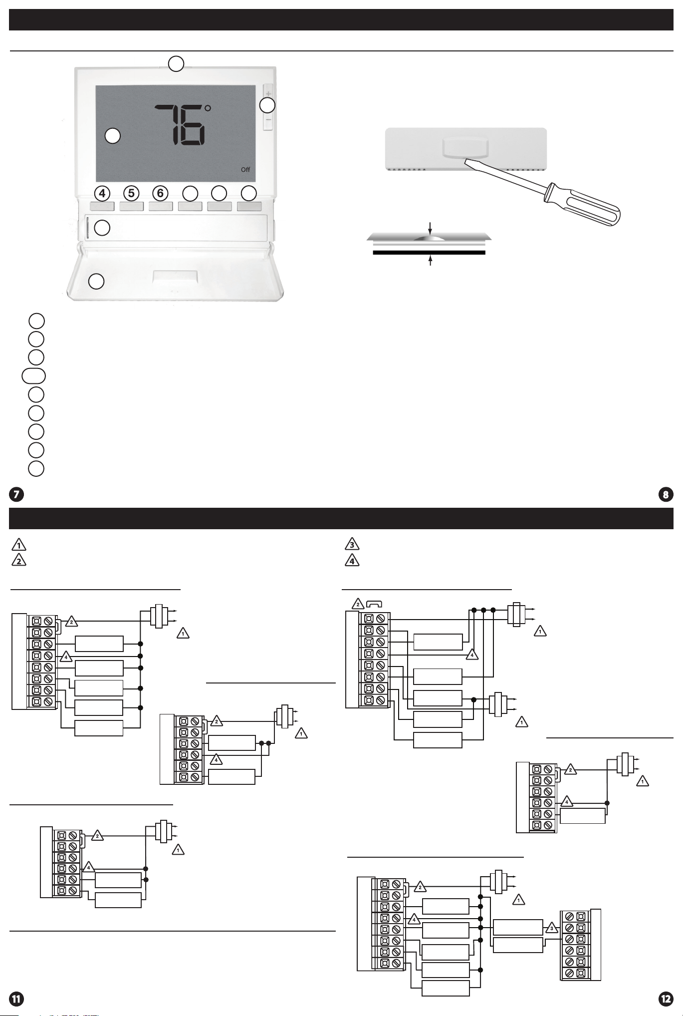
Getting to know your thermostat
PM
5:23
1
1
1
0
1
LCD Display
1
Glow in the dark light button
2
Setpoint buttons
3
Program buttons
4-6
Menu button
7
Fan button
8
System button
9
Button/battery access door
0
1
Battery cover
1
1
2
Menu
7
Tue
F
Auto
About The Badge
All of our thermostats use the same universal magnetic badge. Visit the
company website to learn more about our free private label program.
3
8
9
Use the bevel on lower ridge
Magnet in door
Gently slide a screwdriver into the
bottom edge of the badge. Gently turn
the screwdriver counter clockwise. The
badge is held on by a magnet in the well
of the battery door. The badge should pry
o easily. DO NOT USE FORCE.
Wiring Diagrams Wiring Diagrams
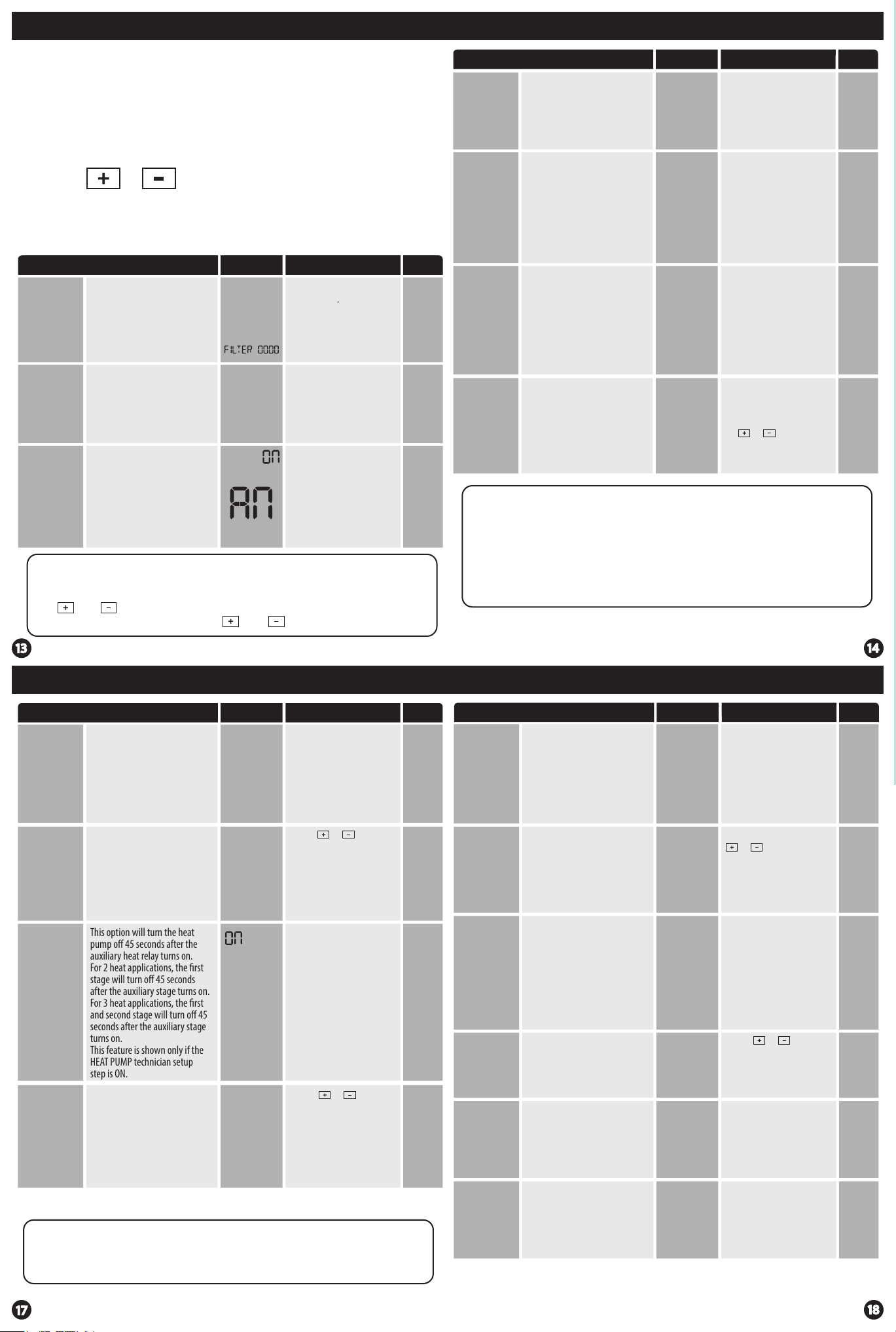
Power supply
Factory-installed jumper. Remove only when installing on 2-transformer systems
Typical 2H/2C System: 1 Transformer Typical 2H/2C System: 2 Transformer
C
L2
RC
RH
W/E
W2
Y2
Y
C
G
COMPRESSOR
RELAY
HEAT RELAY
FAN RELAY
HEAT RELAY 2
COMPRESSOR
RELAY 2
L1(HOT)
R
Typical Cool-Only System
C
L2
RC
RH
W/E
Y
C
G
COMPRESSOR
RELAY
FAN RELAY
L1(HOT)
R
Typical Heat Only System With Fan
C
RC
RH
W/E
Y
C
HEAT RELAY
G
FAN RELAY
L2
L1(HOT)
R
Note:
In many systems with no emergency heat relay a jumper can be installed
between E and W2.
Use either O or B terminals for changeover valve
Optional 24 VAC common connection when thermostat is used in battery power mode
REMOVE JUMPER
RC
RH
Y
C
W/E
G
W2
Y2
COMPRESSOR
RELAY
FAN RELAY
HEAT RELAY
HEAT RELAY 2
COMPRESSOR
RELAY 2
Typical 3H/2C or 2H/1C Heat Pump System
RC
RH
Y
C
W/E
G
W2
Y2
COMPRESSOR
RELAY
EMERGENCY
HEAT RELAY
FAN RELAY
AUXILIARY
HEAT RELAY
COMPRESSOR
RELAY 2
C
R
C
L2
L1(HOT)
R
RC
RH
Y
C
W/E
G
C
L2
L1(HOT)
R
COOL CHANGE
OVER VALVE
HEAT CHANGE
OVER VALVE
L2
L1(HOT)
Typical Heat-Only System
C
L2
L1(HOT)
R
HEAT RELAY
O
B
Page 4
Technician Setup Menu
Technician Setup Menu
This thermostat has a technician setup menu for easy installer
conguration. To set up the thermostat for your particular application:
1. Press the MENU button.
2. Press and hold the TECH SETUP button for 3 seconds. This 3
second delay is designed so that homeowners do not accidentally
access the installer settings.
3. Congure the installer options as desired using the table below.
Use the or keys to change settings and the NEXT
STEP or PREV STEP key to move from one step to another.
Note: Only press the DONE key when you want to exit the
Technician Setup options.
4. Press the DONE key to exit.
Tech Setup Steps
This feature will ash after the
elapsed run time to remind the
Filter Change
Reminder
Room
Temperature
Calibration
Minimum
Compressor
On Time
Keypad Lockout Note: The selected keypad lockout functionality must
be activated after exiting tech setup. If you do not perform this
procedure, all keys will function freely. To lock the keypad hold down
the and keys for 3 seconds. You will see a lock in the display. To
unlock the display hold down the and keys for 3 seconds.
user to change the lter. A setting
of “OFF” will disable this feature.
This feature allows the installer
to change the calibration of the
room temperature display. For
example, if the thermostat reads
70˚ and you would like it to read
72˚ then select +2.
This feature allows the installer
to select the minimum run
time for the compressor. For
example, a setting of 4 will force
the compressor to run for at
least 4 minutes every time the
compressor turns on, regardless
of the room temperature.
LCD Will Show
OFF
SE
CAL
0
OFF
Adjustment Options Default
You can adjust the lter
change reminder from “OFF”
to 2000 hours of runtime in
50 hour increments.
You can adjust the room
temperature display to read
up to 4˚above or below the
O
factory calibrated reading.
F
You can set the minimum
compressor run time to “OFF”,
“3”, “4”, or “5” minutes. If 3,4
or 5 is selected, the
compressor will run for
at least the selected time
before turning o.
OFF
0˚F
OFF
Tech Setup Steps Adjustment Options Default
The compressor short cycle delay
Compressor
Short Cycle
Delay
Cooling
Swing
Heating
Swing
Keypad
protects the compressor from
“short cycling”. This feature will
not allow the compressor to be
turned on for 5 minutes after it
was last turned o.
The swing setting often called
“cycle rate”, “dierential” or
“anticipation” is adjustable. A
smaller swing setting will cause
more frequent cycles and a larger
swing setting will cause fewer
cycles.
The swing setting often called
“cycle rate”, “dierential”, or
“anticipation” is adjustable. A
smaller swing setting will cause
more frequent cycles and a larger
swing setting will cause fewer
cycles.
Keypad lockout allows you to
congure the thermostat so that
some or all of the keys don’t
function.
Lockout
Swing Setting Tip
The second stage will turn on at 2x the swing setting. The second stage
will turn o when 1x the swing is reached. For example, if the swing
setting is .5 degrees for heating and the thermostat is set at 70˚F, the rst
stage will turn on at approximately 69.5˚F. The second stage will turn on
at 69˚F. The second stage will turn o at 69.5˚F and the rst will turn o
at 70.5˚F. If the third stage is used, it will turn on at 3x the swing setting
and turn o at approximately 2x the swing setting.
LCD Will Show
ON OF
CO
dFCO
0.5
dFHE
0.4
PA
LOCKOUT
Selecting “ON” will not allow
the compressor to be turned
on for 5 minutes after the
last time the compressor was
on. Select “OF” to remove
this delay.
The cooling swing setting
is adjustable from 0.2˚ to
2˚. For example: A swing
setting of 0.5˚ will turn the
cooling on at approximately
0.5˚ above the setpoint
and turn the cooling o at
approximately 0.5˚ below
the setpoint.
The heating swing setting is
adjustable from 0.2˚ to 2˚.
For example: A swing setting
of 0.5˚ will turn the heating
on at approximately 0.5˚
below the setpoint and turn
the heating o at 0.5˚ above
the setpoint.
OF= keypad lockout has been
disabled.
PA= partial keypad lockout,
which locks all the keys except
the or keys.
FU= full keypad lockout,
which locks out all the keys.
See Keypad Lockout Note
ON
0.5˚
0.4˚
OF
Technician Setup Menu
Tech Setup Steps
When turned on the thermostat
will operate a heat pump.
1. EM. Heat will show as an option
Heat Pump
System Set
Gas Auxiliary
for Heat
Pump
Stages of
Heat
A Note about IAQ Mode
This programmable/selectable mode will operate the fan 1-4 cycles per hour,
1-45 minutes per cycle. Once programmed in tech setup, to enable this mode
select “IAQ” with the fan key. Disable this mode by selecting “ON” or “AUTO” with
the fan key.
in the system switch.
2. Y will be rst stage of heat
& cool, W/E will be emergency
heat relay & W2 will be auxiliary
heat relay.
You can congure the system
switch for the particular
application.
Heat - O - Cool, Heat - O, Cool O, Heat - O - Cool - Auto
Note: EM. Heat will show if in
heat pump mode.
This option will turn the heat
pump o 45 seconds after the
auxiliary heat relay turns on.
For 2 heat applications, the rst
stage will turn o 45 seconds
after the auxiliary stage turns on.
For 3 heat applications, the rst
and second stage will turn o 45
seconds after the auxiliary stage
turns on.
This feature is shown only if the
HEAT PUMP technician setup
step is ON.
You can congure the thermostat
to operate a 3 stage heat pump
system.
2H 2C = 2 heat, 2 cool
3H 2C = 3 heat, 2 cool
This feature is shown only if the
HEAT PUMP technician setup
step is ON.
LCD Will Show
OFF
HEAT
OFF
COOL
A6
2H2C
Adjustment Options
OFF congures the thermostat
for non heat pump systems.
ON congures the thermostat
for heat pump systems.
Use the or key until
the desired application is
ashing.
AUTO=
(Auto Changeover)
For heat pump systems that
are “dual fuel” (use a gas or
other fossil fuel furnace for
auxiliary stage heat) you can
turn this feature on to turn
o the heat pump when the
auxiliary stage of heating
has been called for.
Use the or key to
change between 2 or 3
stages of heat. 2 heat will
use Y1 as rst stage and W2
as auxiliary.
3 heat will use Y1 as the rst
stage, Y2 as the second stage
and W2 as the auxiliary.
Default
OFF
HEAT
OFF
COOL
OFF
2
STAGES
Technician Setup Menu
Tech Setup Steps Adjustment Options Default
The cooling fan delay setting will
delay the fan from coming on in
cool mode and keep it running
Cooling Fan
Delay
IAQ Mode
Cycle
IAQ Mode
Minutes
Remote
Sensor
Operation
Local Temp
Sensor
Number
of Indoor
Remotes
after the compressor shuts o
for a short time to save energy in
some systems.
This feature will congure the fan
to run a selected number of cycles
per hour.
Note: This mode can be enabled
or disabled at anytime during
normal operation by selecting IAQ
mode with the fan key.
This allows you to select the
minimum number of minutes
that the fan will run per IAQ mode
cycle. The thermostat will keep
track of fan runtime from normal
heat and cool operation. If additional fan runtime is needed, the
thermostat will run the fan to
satisfy the IAQ mode minutes.
You can congure the thermostat
for one of three remote sensor
applications: 0 No Sensor, 1
Indoor, 2 Outdoor, 3 Floor.
You can disable the sensor on the
T855S thermostat. At least one
R251S indoor remote sensor must
be connected to disable the local
T855S sensor. Note: Will only
show if remote sensor is set to 1.
Enables the use of up to sixteen
indoor sensors R251S.
Note: Will only show Remote
Sensor is set to 1 and Local Temp
Sensor is set to on.
LCD Will Show
COOL
FAN DL
IAQ
MODE
CYCLE
IAQ
MODE
MINUT
1
REMOTE
MODE
ON
LOCAL
TEMP
1
NUMBER
OF
REMO
You can set the cooling fan
delay to OFF, 15, 30, 60 or 90
seconds. If 15, 30, 60, or 90 is
selected the fan will not turn
on for that many seconds
when there is a call for cool
and will run for that many
seconds after satisfying a call
for cool.
Select OFF, 1, 2, 3 or 4 with the
or keys.
This sets the number of cycles
per hour that the IAQ fan mode
will operate.
Select 1, 5, 10, 15, 20, 30 or
45 minutes.
When IAQ fan mode is
enabled, it will ensure the
fan runs at least the selected
number of minutes per IAQ
Mode Cycle.
This step will not appear if
previous step is set to “OFF”.
Use the or keys to
select one of three options.
View the S1/S2 terminal chart
on next page for an
explanation of these options.
ON enables local T855S sensor.
OFF disables local T855S
sensor.
You can use 1, 4, 9, or 16
indoor sensors. Refer to the
R251S Install Manual for
detailed connection
information.
OFF
OFF
1
0
ON
ON
Page 5
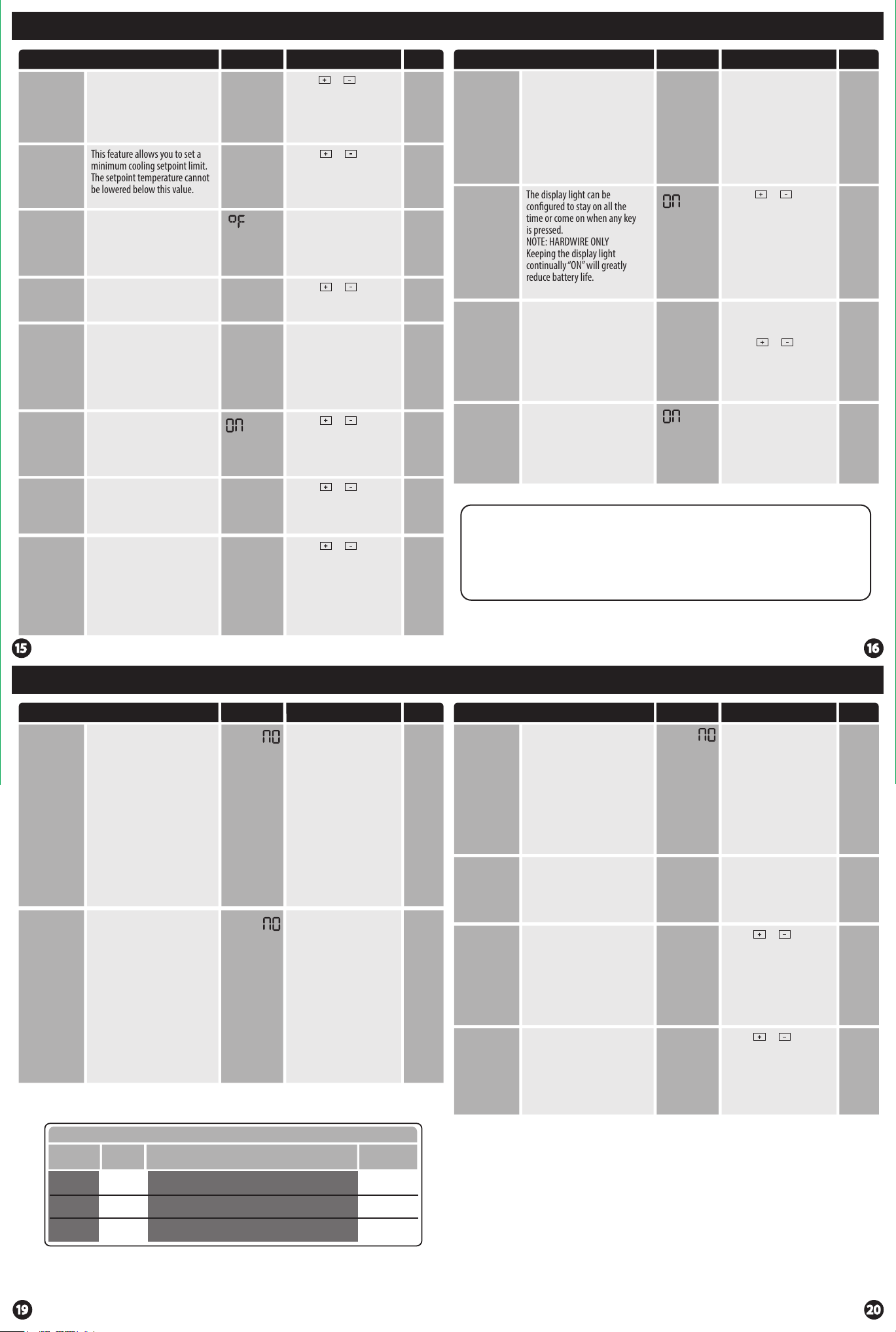
Technician Setup Menu Technician Setup Menu
Tech Setup Steps
Heating
Temperature
Setpoint
Limit
Cooling
Temperature
Setpoint
Limit
˚F or ˚C
12 or 24
Hour Clock
Fan
Operation
Morning
Recovery
Program
Options
Time Periods
This feature allows you to set a
maximum heating setpoint limit.
The setpoint temperature cannot
be raised above this value.
This feature allows you to set a
minimum cooling setpoint limit.
The setpoint temperature cannot
be lowered below this value.
This feature allows you to display
temperatures in either Fahrenheit
or Celsius.
You can select either a 12 or 24
hour clock setting.
Select GAS for systems that control
the fan during a call for heat.
Select ELEC to have the thermostat
control the fan during a call for
heat. Note: If heat pump is set to
“ON” this step will not show, and
will default to ELEC.
This feature will start heating
early to bring the building
temperature to its programmed
setpoint by the beginning of the
WAKE, OCCUPIED time period.
You can congure this thermostat
to have a 7 day program, a
5+1+1 program or as
nonprogrammable.
You can congure this thermostat
to have 2 or 4 programmable time
periods per day. 4 time periods
are Wake, Leave, Return & Sleep.
2C time periods are Occupied
& Unoccupied. 4C time periods
are Occupied 1, Unoccupied 1,
Occupied 2, & Unoccupied 2.
LCD Will Show
90
HE
44
CO
78
12H
ELE
5d
4
4
Adjustment Options Default
Use the or key to
select the maximum heat
setpoint.
Use the or key to
select the minimum cool
setpoint.
˚F for Fahrenheit
˚C for Celsius
O
F
Use the or key to
select 12 or 24 hour clock.
GAS or ELEC
Use the or key to
turn on or o.
Use the or key to
select 7d for 7 day, 5d for
5+1+1, or 0d for
nonprogrammable.
Use the or key to
select 4, 2c, or 4c time periods
per day.
90˚F
44˚F
˚F
12
HOUR CLOCK
GAS
ON
5d
4
Tech Setup Steps Adjustment Options Default
The pre-occupancy fan settings
will energize the fan before
the occupied time to provide
Pre-Occupancy
Fan
Display Light
Contractor
ventilation prior to scheduled
occupancy.
This feature only shows if the
technician setup step for time
periods is set to 2C or 4C.
The display light can be
congured to stay on all the
time or come on when any key
is pressed.
NOTE: HARDWIRE ONLY
Keeping the display light
continually “ON” will greatly
reduce battery life.
Allows you to put your phone
number in the display.
You can choose ON or OFF.
Call Number
When any key is pressed an
audible beep will sound.
Beep
You can choose ON or OFF.
LCD Will Show
OFF
PRE
OCCUPY
FAN
dL
OFF
You can select the
pre-occupancy fan from OFF,
1, 2, or 3 hours.
If 1, 2, or 3 is selected, the
fan will turn on that many
hours prior to the scheduled
occupied time period.
Use the or key to to
turn on or o.
OFF congures the display
light to come on when the
light key or any button is
pressed.
ON congures the display
light to stay on.
If selected ON, you will
see the input screen after
pressing NEXT STEP.
Use the or key to
select the desired number
and the FAN or SYSTEM key
to move from one character
to another. See note below
for operation.
If ON is selected the beep
will sound.
If OFF is selected there is no
sound.
OFF
OFF
OFF
ON
b
Contractor Call Number Note
If contractor call number is selected ON, the phone number entered will
show in the display if there has been a continuous call for heating or
cooling for 24 hours or if the light button is held down for 3 seconds. To
remove the phone number from the display, hold the light button down
for 3 seconds.
Technician Setup Menu
Tech Setup Steps Adjustment Options Default
An outdoor temperature above
balance point will cause the
thermostat to only allow the Y
terminal(s) to energize. An
outdoor temperature below
Balance Point
(Gas
Auxiliary On)
Balance Point
(Gas
Auxiliary O )
balance point will cause the
thermostat to only allow W2 to
energize. Note: This setting only
shows up if heat pump is set to
Yes and Remote Sensor is set to 2.
Balance point with electric
auxiliary can optimize heat pump
usage. An outdoor temperature
above balance point will cause
the thermostat to only allow the Y
terminal(s) to energize. An
outdoor temperature below
balance point will cause the thermostat to allow the Y terminal(s)
and the W2 terminal to energize.
Note: Only shows if Heat Pump
is set to Yes and Remote Sensor
is set to 2.
LCD Will Show
bAL
POINT
bAL
POINT
10, 20, 30, 35, 40, 45, 50
outdoor temperature balance
point setting.
NO
NO
10, 20, 30, 35, 40, 45, 50
outdoor temperature
balance point setting.
NO
NO
Programming
Tech Setup Steps Adjustment Options Default
Balance point run time will allow
the W2 auxiliary terminal to energize even if outdoor temperature
is above selected balance point
Balance Run
Time
Floor
Temperature
Floor High
Limit
Floor Low
Limit
temperature. If enabled, auxiliary
will energize for the current cycle
after the balance point run time
has expired.
Note: Only shows if Balance Point
is set to an outdoor temperature.
The temperature of the oor
sensor will be displayed.
Note: Only shows when REOP is
set to 3.
This setting allows you to set
a maximum oor temperature
limit for heat. Heat will be locked
out when the oor temperature
is above this value. Note: Only
shows when REOP is set to 3.
Note: Only shows when REOP is
set to 3.
This setting allows you to set
a minimum oor temperature
limit for heat. Heat will turn on
automatically when the oor
temperature is below this value.
Note: Only shows when REOP is
set to 3.
LCD Will Show
bAL
RUN
TIME
76
FLOORTEMP
86
HIGH
LIMIT
50
LO
LIMIT
15, 30, 45, 60, 75, 90
NO
N/A
1
Use the or keys to
select the High Limit for the
oor sensor.
35 - 120
Use the or keys to
select the Low Limit for the
oor sensor.
35 - 120
OFF
NA
86
50
Options Mode
1
Indoor
Outdoor
2
3
Floor
S1 / S2 Terminal
Description
The local and remote temperatures are averaged.
The outdoor temperature is ashed in clock.
The oor temperature is shown in tech.
Requires
R251S
R250S
R250S
Page 6
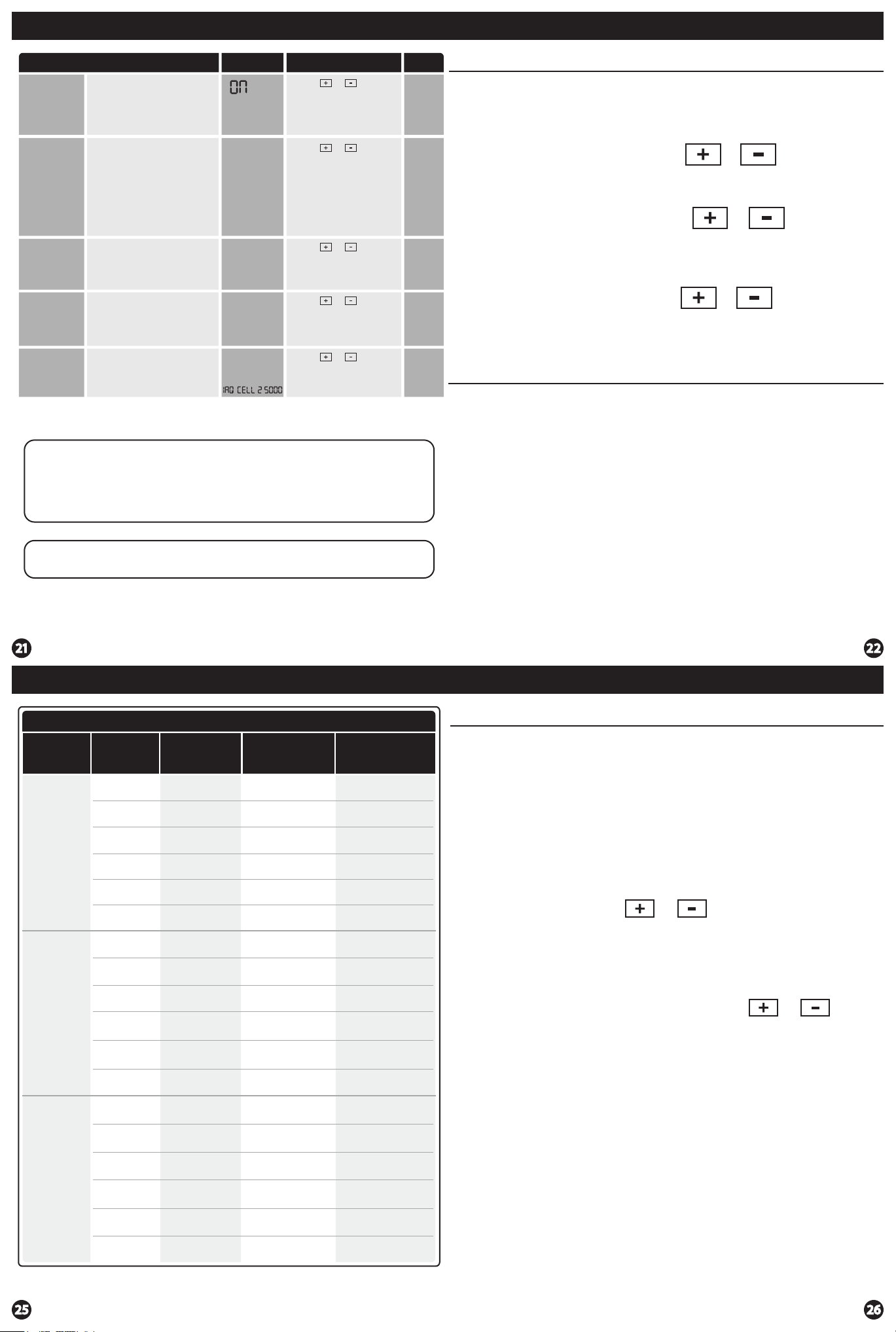
Programming
Programming
Tech Setup Steps Adjustment Options Default
This feature allows the
Satisfy
Setpoint
Staging
Delay
Humidity Pad
thermostat to keep multiple
stages of heat or cool energized
until the setpoint is satised.
This feature allows a delay to
occur if an additional stage is
needed. This allows the previous
stage extra time to satisfy the
setpoint. Note: Will not show
if using outdoor sensor with
balance point temperature.
Enables a reminder for the user to
change the humidity pad.
Reminder
Enables a reminder for the user to
UV Lamp
change the UV light bulb.
Reminder
IAQ Cell
Reminder
Reminders
Once a reminder has been turned on and set, the elapsed time can be checked
by navigating to its tech setup step. The elapsed time will then appear in the
text eld. It can also be reset at that time by holding down the set time/run
sched button for 3 seconds. Resetting an expired reminder can be done without
entering tech setup, by holding down the set time/run sched button for 3
seconds from the home screen.
Enables a reminder for the user
to change the PHI Cell after
25,000 hrs.
LCD Will Show
SS STAGING
5
STAGING dl
OFF
HUM PAD 2000
OFF
UVLAMP 00000
250
Use the or key to
turn on or o.
Use the or key to
select OFF, 5, 10, 15, 30, 45,
60, or 90 minutes.
Use the or key to
select OFF, 600, 1000, 1500,
or 2000. These represent
hours of heat operation.
Use the or key to
select OFF, 1YEAR, 2YEAR.
Use the or key to
select OFF, or 250 (stands for
25,000 hours).
OFF
OFF
OFF
OFF
OFF
Set Time
Follow the steps below to set the day of the week and current time:
1. Press the MENU button.
2. Press SET TIME.
3. Day of the week is ashing. Use the or key to
select the current day of the week.
4. Press NEXT.
5. The current hour is ashing. Use the or key to
select the current hour. When using 12-hour time, make sure
the correct a.m. or p.m. choice is selected.
6. Press NEXT.
7. Minutes are now ashing. Use the or key to
select current minutes.
8. Press DONE when completed.
Programming
All our programmable thermostats are shipped with an energy saving default
program. You can customize this default program by following the
instructions in the set program schedule section starting on page 24.
Your thermostat can be programmed to have each day of the week
programmed uniquely (7 days), all the weekdays the same with a separate
program for Saturday and a separate program for Sunday (5+1+1), or
non-programmable. For the 7-day and 5+1+1 programming modes, there are
three time period options.
1. “4” Residential (WAKE, LEAVE, RETURN, SLEEP)
Staging Delay Note: This step will not appear if using an outdoor balance point
temperature.
Programming
Custom Program
Day of
the Week
Weekday
Saturday
Events Time
Wake/OCC1
Leave/UNOCC1
Return/OCC2
Sleep/UNOCC2
Occupied
Unoccupied
Wake/OCC1
Leave/UNOCC1
Return/OCC2
Sleep/UNOCC2
Occupied
Unoccupied
Wake/OCC1
Setpoint
Temperature
(HEAT)
Setpoint
Temperature
(COOL)
2. “2C” Commercial (OCCUPIED, UNOCCUPIED)
3. “4C” Commercial (OCCUPIED 1, UNOCCUPIED 1, OCCUPIED 2, UNOCCUPIED 2)
This thermostat has a programmable fan feature, which allows you to run the
fan continually during any time period.
Programming
Set Program Schedule For Four Time Periods
(WAKE, LEAVE, RETURN, SLEEP or OCCUPIED 1, UNOCCUPIED1, OCCUPIED 2, UNOCCUPIED 2)
To customize your 5+1+1 Program schedule, follow these steps:
Weekday:
1. Select HEAT or COOL with the system switch.
Note: You have to program heat and cool each separately.
2. Press the MENU button (If menu does not appear rst press
RUN SCHED).
3. Press SET SCHED. Note: Monday-Friday is displayed and the
WAKE/OCC1 icon is shown. You are now programming the
WAKE/OCC1 time period for the weekday setting.
4. Time is ashing. Use the or key to make your time
selection for the weekday WAKE/OCC1 time period.
Note: If you want the fan to run continuously during this time
period, select ON with the FAN key. If you want to use IAQ
mode during this time period, select IAQ with the FAN key.
5. Press NEXT.
6. The setpoint temperature is ashing. Use the or key
to make your setpoint selection for the weekday WAKE/OCC1
period.
7. Press NEXT.
8. Repeat steps 4 through 7 for the weekday LEAVE/UNOCC1
time period, for the weekday RETURN/OCC2 time period,
and for the weekday SLEEP/UNOCC2 time period.
Sunday
LeaveUNOCC1
Return/OCC2
Sleep/UNOCC2
Occupied
Unoccupied
Saturday:
Repeat steps 4 through 7 for the Saturday WAKE/OCC1 time period,
for the Saturday LEAVE/UNOCC1 time period, for the Saturday
RETURN/OCC2 time period, and for the Saturday SLEEP/UNOCC2
time period.
Sunday:
Repeat steps 4 through 7 for the Sunday WAKE/OCC1 time period,
for the Sunday LEAVE/UNOCC1 time period, for the Sunday
RETURN/OCC2 time period, and for the Sunday SLEEP/UNOCC2
time period.
Page 7
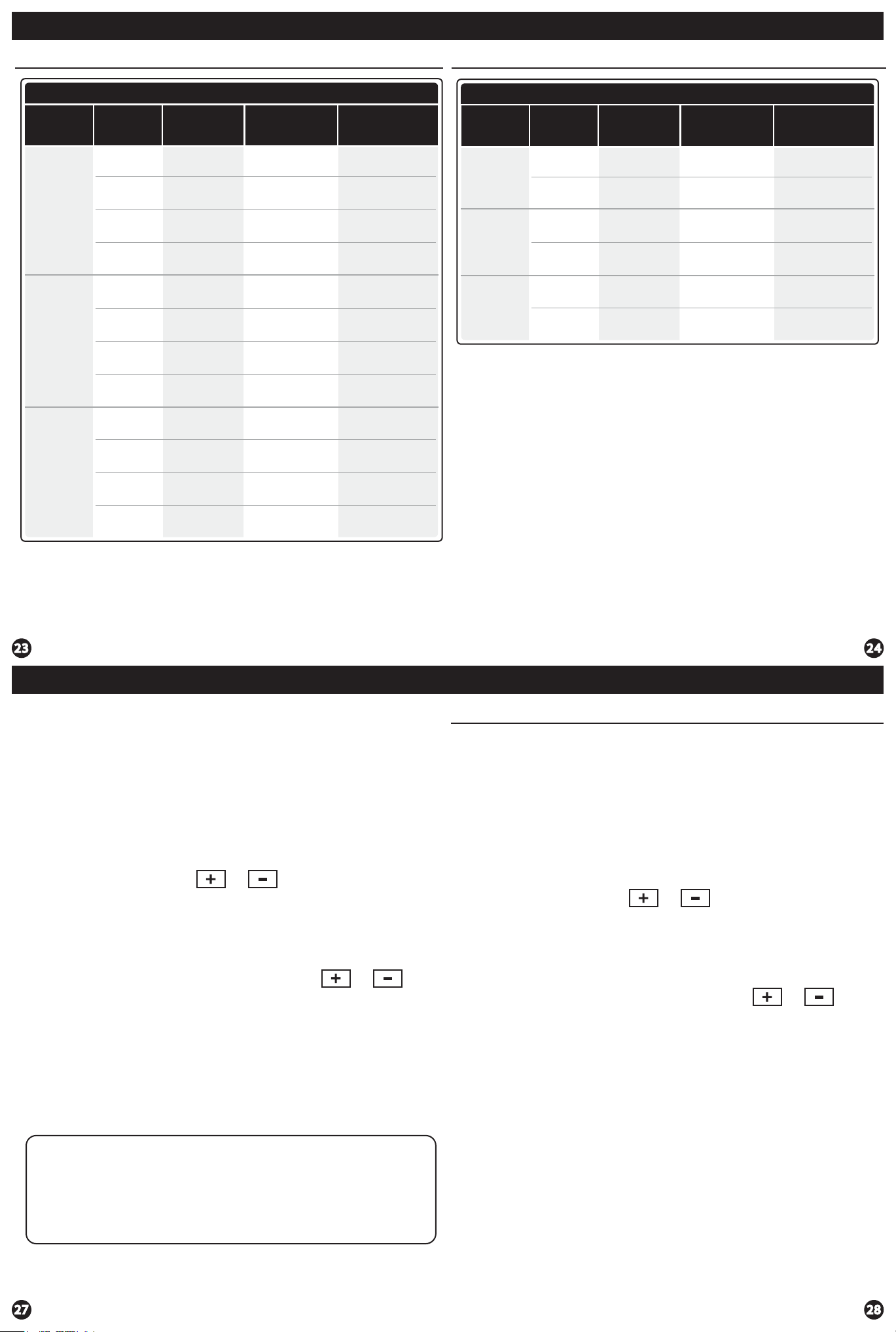
Programming
Programming
Default Programming
Factory Default Program
Day of
the Week
Weekday
Saturday
Events Time
Wake/OCC1
Leave/UNOCC1
Return/OCC2
Sleep/UNOCC2
Wake/OCC1
Leave/UNOCC1
Return/OCC2
Sleep/UNOCC2
Wake/OCC1
6 AM
8 AM
6 PM
10 PM
6 AM
8 AM
6 PM
10 PM
6 AM
Setpoint
Temperature
(HEAT)
70˚F (21˚C)
62˚F (17˚C)
70˚F (21˚C)
62˚F (17˚C)
70˚F (21˚C)
62˚F (17˚C)
70˚F (21˚C)
62˚F (17˚C)
70˚F (21˚C)
Setpoint
Temperature
(COOL)
75˚F (24˚C)
83˚F (28˚C)
75˚F (24˚C)
78˚F (26˚C)
75˚F (24˚C)
83˚F (28˚C)
75˚F (24˚C)
78˚F (26˚C)
75˚F (24˚C)
Default Programming
Factory Default Program for 2 Time Periods
Day of
the Week
Events Time
OCCUPIED
8 AM
Setpoint
Temperature
(HEAT)
70˚F (21˚C)
Weekday
UNOCCUPIED
OCCUPIED
6 PM
8 AM
62˚F (17˚C)
70˚F (21˚C)
Saturday
UNOCCUPIED
OCCUPIED
6 PM
8 AM
62˚F (17˚C)
70˚F (21˚C)
Sunday
UNOCCUPIED
You can use the table on the next page to plan your customized program
schedule if using 5+1+1.
6 PM
62˚F (17˚C)
Setpoint
Temperature
(COOL)
78˚F (26˚C)
83˚F (28˚C)
78˚F (26˚C)
83˚F (28˚C)
78˚F (26˚C)
83˚F (28˚C)
LeaveUNOCC1
8 AM
62˚F (17˚C)
83˚F (28˚C)
Sunday
Return/OCC2
Sleep/UNOCC2
6 PM
10 PM
70˚F (21˚C)
62˚F (17˚C)
75˚F (24˚C)
78˚F (26˚C)
Programming Programming
To customize your 7 day Program schedule, follow these steps:
Monday:
1. Select HEAT or COOL with the SYSTEM key.
Note: You have to program heat and cool each separately.
2. Press the MENU button (If menu does not appear rst, press
RUN SCHED).
3. Press SET SCHED. Note: Monday is displayed and the
WAKE/OCC1 icon is shown. You are now programming the
WAKE/OCC1 time period for the Monday setting.
4. Time is ashing. Use the or key to make your time
selection for the Monday WAKE/OCC1 time period.
Note: If you want the fan to run continuously during this time
period, select ON with the FAN key. If you want to use IAQ
mode during this time period, select IAQ with the FAN key.
5. Press NEXT.
6. The setpoint temperature is ashing. Use the or key
to make your setpoint selection for the Monday WAKE/OCCU1
period.
7. Press NEXT.
8. Repeat steps 4 through 7 for the Monday LEAVE/UNOCC1
time period, for the Monday RETURN/OCC2 time period,
and for the Monday SLEEP/UNOCC2 time period.
Set Program Schedule For Two Time Periods
To customize your 5+1+1 Program schedule, follow these steps:
Weekday:
1. Select HEAT or COOL with the SYSTEM key.
Note: You have to program heat and cool each separately.
2. Press the MENU button (If menu does not appear rst, press
RUN SCHED).
3. Press SET SCHED. Note: Monday-Friday is displayed and the
OCCUPIED text is shown. You are now programming the
OCCUPIED time period for the weekday setting.
4. Time is ashing. Use the or key to make your time
selection for the weekday OCCUPIED time period.
Note: If you want the fan to run continuously during this time
period, select ON with the FAN key. If you want to use IAQ
mode during this time period, select IAQ with the fan key.
5. Press NEXT.
6. The setpoint temperature is ashing. Use the or key
to make your setpoint selection for the weekday OCCUPIED
period.
7. Press NEXT.
8. Repeat steps 4 through 7 for the weekday UNOCCUPIED
time period.
(OCCUPIED, UNOCCUPIED)
Repeat steps 4 through 8 for the remaining days of the week.
A Note About Auto Changeover:
In Auto you have the ability to switch between Auto Heat or Auto Cool
by pressing the system key. This can be done once the current mode has
reached its setpoint. For example: if in Auto Heat, the heat setpoint must
be satised before the thermostat will allow you to switch to Auto Cool.
You can switch out of Auto by holding down the system key. To get back
into Auto, you must toggle the system key to Auto.
Saturday:
Repeat steps 4 through 7 for the Saturday OCCUPIED time period
and for the Saturday UNOCCUPIED time period.
Sunday:
Repeat steps 4 through 7 for the Sunday OCCUPIED time period, and
for the Sunday UNOCCUPIED time period.
Page 8
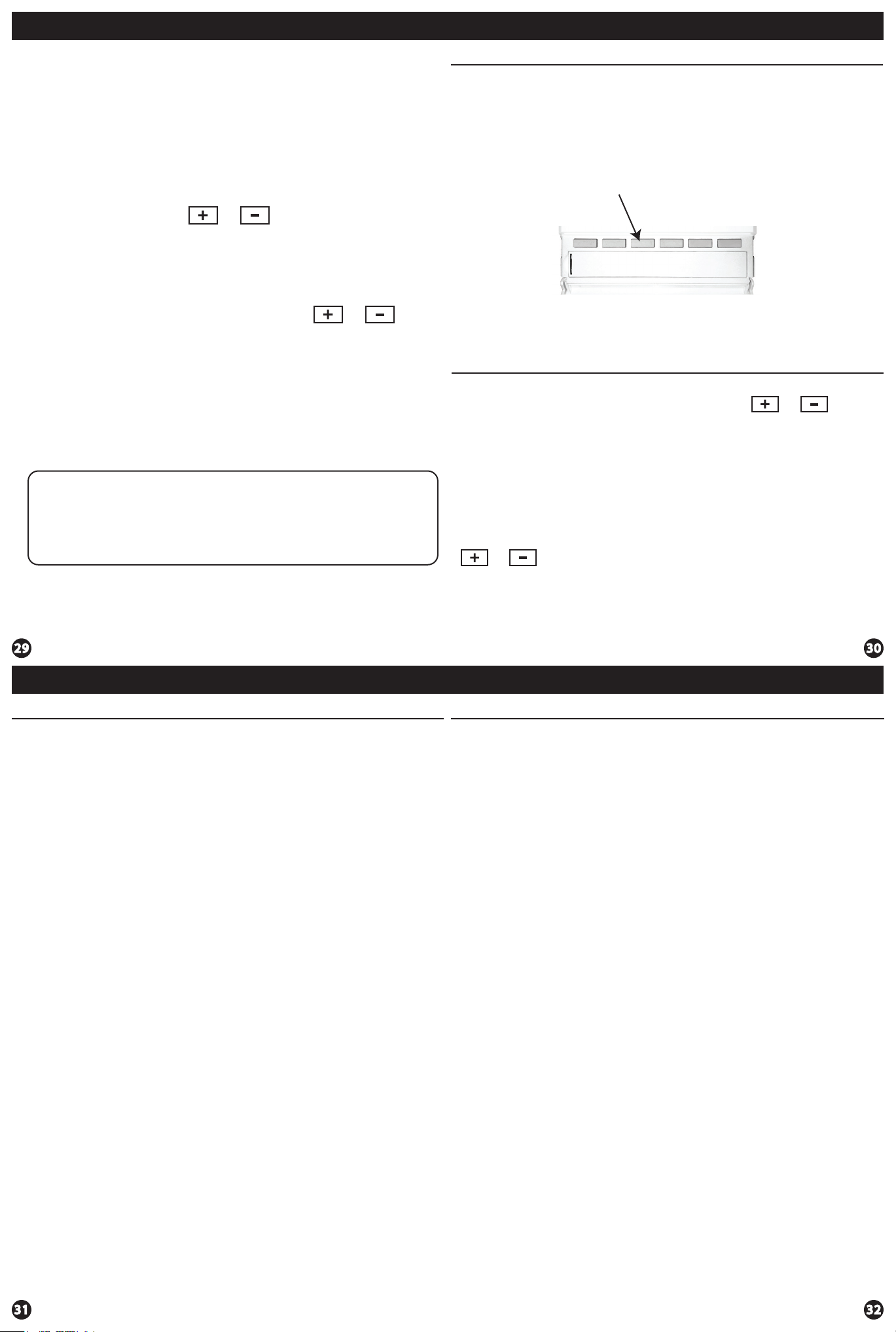
Programming
Features
To customize your 7 day program schedule, follow these steps:
Monday:
1. Select HEAT or COOL with the SYSTEM key.
Note: You have to program heat and cool each seperately.
2. Press the MENU button (If menu does not appear rst press
RUN SCHED).
3. Press SET SCHED. Note: Monday is displayed and the
OCCUPIED text is shown. You are now programming the
UNOCCUPIED time period for the monday setting.
4. Time is ashing. Use the or key to make your time
selection for the Monday WAKE/OCC1 time period.
Note: If you want the fan to run continuously during this time
period, select ON with the FAN key. If you want to use IAQ
mode during this time period, select IAQ with the fan key.
5. Press NEXT.
6. The setpoint temperature is ashing. Use the or key
to make your setpoint selection for the Monday OCCUPIED
period.
7. Press NEXT.
8. Repeat steps 4 through 7 for the the Monday UNOCCUPIED
time period.
Repeat steps 4 through 8 for the remaining days of the week.
Filter Change & Other Reminders
If the lter change reminder is enabled, you will see FILT in the
display when your air lter needs changed. FILT will be shown in the
display after your system has run long enough to require an air lter
change.
Resetting The Filter Change Reminder: When FILT reminder is
displayed, you should change your air lter and reset the reminder by
holding down the 3rd button from the left side of the thermostat for
3 seconds.
This thermostat also has other maintenance reminders (Humidity
Pad, UV lamp, and IAQ Cell), that are reset with the same procedure.
Temporary & Permanent Hold Feature
Temporary Hold: The thermostat will display HOLD and RUN SCHED
on the bottom of the screen when you press the or
key. If you do nothing, the temperature will remain at this setpoint
temporarily for 4 hours. The program setpoint will then replace the
temporary setpoint.
A Note About Programmable Fan:
The programmable fan feature will run the fan continuously during any
time period it is programmed to be on. This is the best way to keep the
air circulated and to eliminate hot and cold spots in your building. If
using IAQ mode, set fan to IAQ for any time period.
Remote Sensor Operation
Remote Sensor Operation Options
Option #1 - Indoor / Local Temperature Sensor “ON”:
1. The displayed room temperature will display the average
temperature of the thermostat and all remote sensors.
2. By pressing the far left (Prev Step) button, the average temperature
of just the remote sensor(s) will be displayed briey in the clock eld.
Option #1 - Indoor / Local Temperature Sensor OFF”:
Permanent Hold: With a temporary hold set, If you press the HOLD
key at the bottom of your screen, you will see HOLD appear below
the setpoint temperature in the display. The thermostat will now
permanently stay at this setpoint and can be adjusted using the
or keys.
To Return To Program: Press the RUN SCHED key at the bottom of
the screen to exit temporary and permanent holds.
Specications
Specications
The display range of temperature ... 41˚F to 95˚F (5˚C to 35˚C)
The control range of temperature.... 44˚F to 90˚F (7˚C to 32˚C)
Load Rating............................................... 1 amp per terminal, 1.5 amp
maximum all terminals combined
Swing (cycle rate or dierential) ...... Heating is adjustable from 0.2˚ to 2.0˚
Cooling is adjustable from 0.2˚ to 2.0˚
Power source ...........................................18 to 30 VAC, NEC Class II, 50/60 Hz
for hardwire
Battery power from 2 AA Alkaline
batteries
Operating ambient ............................... 32˚F to +105˚F (0˚C to +41˚C)
Operating humidity .............................. 90% non-condensing maximum
Dimensions of thermostat ................. 4.7” W x 4.3” H x 0.9” D
1. The displayed room temperature will only show the average
temperature of the remote sensor(s).
Option #2 - Outdoor:
1. The outdoor temperature will alternate briey with the clock
display.
Option #3 (Floor)
1. By pressing the far left (Prev. Step) button, the temperature of the
oor sensor will be displayed briey in the clock eld.
 Loading...