

PRM NEWAGE 415 Series, 416-9820, 416-2000, 416-2010, 415-2180 Workshop Manual
...
415B12L062
WORKSHOP
MANUAL

PRM NEWAGE LIMITED
BARLOW ROAD
COVENTRY
CV2 2LD
ENGLAND
TELEPHONE: +44 (0)24 7661 7141
FAX: +44 (0)24 7661 1845
EMAIL: mail@prm-newage.com
WEBSITE: www.prm-newage.com
415B12L062 Manual
Issue: 1.2
Created By: S HYLANDS
Updated: February 2019
This manual contains proprietary information of PRM Newage Limited. It is intended solely for the information
and use of parties operating and maintaining the equipment described herein. Such proprietary information
may not be used, reproduced, or disclosed to any other parties for any other purpose without the express
written permission of PRM Newage Limited.
PRM Newage Ltd operates a policy of product improvement and therefore reserves the right to change
specifications without prior notification. Whilst every effort is made to ensure complete accuracy of the
information in this manual no liabilities for inaccuracies or the consequences thereof can be accepted by the
manufacturer or the distributor who supplied the manual.
The following international symbols are used in this service manual:
WARNING! THIS SYMBOL WARNS OF POSSIBLE PERSONAL INJURY
CAUTION! THIS SYMBOL WARNS OF POSSIBLE DAMAGE TO TRANSMISSION
2

CONTENT
INTRODUCTION ....................................................................................................................................................... 5
GENERAL DATA ........................................................................................................................................................ 5
Description ........................................................................................................................................................... 5
Specification ........................................................................................................................................................ 5
Installation Drawing ............................................................................................................................................. 6
IDENTIFICATION ....................................................................................................................................................... 7
GENERAL SERVICE INFORMATION ........................................................................................................................... 8
Routine Maintenance .......................................................................................................................................... 8
Lubricants ............................................................................................................................................................ 8
Greases ................................................................................................................................................................ 8
Brake Fluid ........................................................................................................................................................... 8
Liquid Sealant ...................................................................................................................................................... 8
Fastener Tightening Torques ............................................................................................................................... 9
Axle Backlash ....................................................................................................................................................... 9
Tooling ................................................................................................................................................................. 9
SERVICING AND REPAIRS ....................................................................................................................................... 10
Seals ................................................................................................................................................................... 10
Bearings ............................................................................................................................................................. 10
Cleaning ............................................................................................................................................................. 10
INSPECTION ........................................................................................................................................................... 11
Main Case and Arms .......................................................................................................................................... 11
Gears .................................................................................................................................................................. 11
Bearings ............................................................................................................................................................. 11
Threaded Parts .................................................................................................................................................. 11
PROCEDURES ......................................................................................................................................................... 11
Section ‘A’ – 415B12L062 Axle Assembly .......................................................................................................... 12
REMOVING & SERVICING THE CROWN WHEEL AND PINION. ........................................................................... 15
Section ‘B’ – Main Case and Differential Assembly ........................................................................................... 17
Servicing the Main Case and Differential Assemblies ...................................................................................... 19
Removing the Differential ................................................................................................................................ 19
Servicing the Differential Assembly ................................................................................................................. 19
Section ‘C’ – Planet Carrier Assembly ................................................................................................................ 20
Servicing the Planet Carrier Assemblies ........................................................................................................... 21
Removing the Annulus Gear ............................................................................................................................ 22
Section ‘D’ – Axle Arm, Hub and Brake Assemblies ........................................................................................... 22
Servicing the Axle Arm, Hub and Brake Assemblies ......................................................................................... 24
Servicing the Brake Assemblies ........................................................................................................................ 24
SPARES KITS ........................................................................................................................................................... 25
3

SPIRAL BEVEL GEAR TOOTH CONTACT .................................................................................................................. 27
Correct Pattern .................................................................................................................................................. 27
Incorrect Pattern ............................................................................................................................................... 27
NOTES ................................................................................................................................................................ 29
4

INTRODUCTION
Spare parts for Newage axles may only be obtained from the original equipment manufacturer and
not directly from Newage. Always quote your vehicle/machine serial number and axle serial number
– see section titled 'Identification'.
If possible, the repair/service should be carried out in a clean environment. Where this is not possible, and the work must be completed on site, appropriate measures must be taken to ensure that
dirt or foreign matter does not enter the unit. Newage axles are designed to operate in the arduous
conditions found in the construction industry; providing they are maintained regularly they will provide the service our customers expect from Newage products.
GENERAL DATA
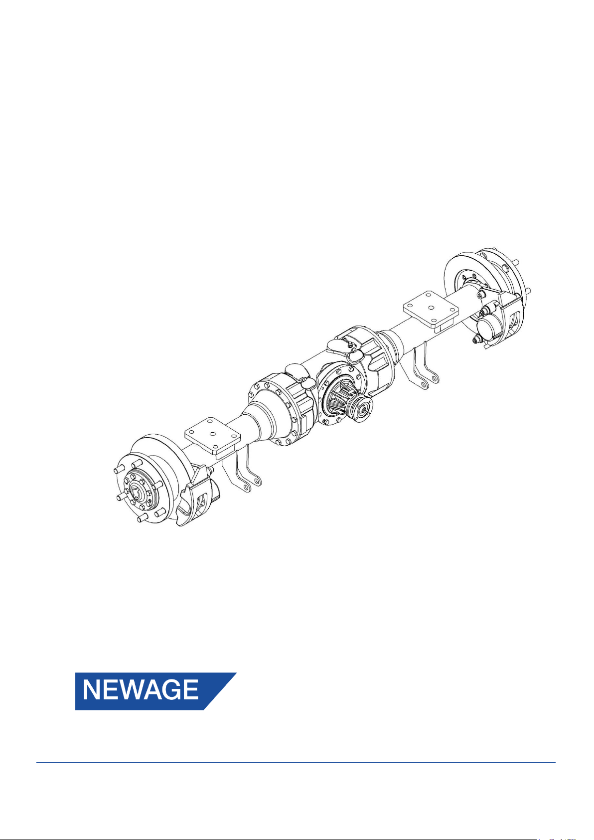
Description
The 415 series axle is a double reduction unit featuring a Hydraulic Disc Braking system.
The 1st reduction Spiral Bevel Pinion and Crown Wheel driving a 4 Pinion Differential. Final drive is
transmitted via the 2nd reduction in-board Planetary Assemblies. The Axle Shafts are fully floating
(i.e. not subjected to wheel loads) with each Wheel Hub supported on opposed taper Roller Bearings.
Specification
Overall Ratio
12.33:1
Input Flange
To suit Hardy Spicer 1310 Coupling
Wheel Fixing
6 studs: 3/4” x 16 UNF-3A on 222.25 mm (8.75”) PCD
Dynamic Axle Load Rating
Maximum load rating 5200 Kg (11440 lbs) based on 1793.75 mm (70.62”) wheel track
Service Brake
See Torque/Pressure Graph
Park Brake
Not Applicable.
Approximate weight
180 kg (397 lb) dry
Oil Capacity
6.5 litres (11.4 Pints)
5
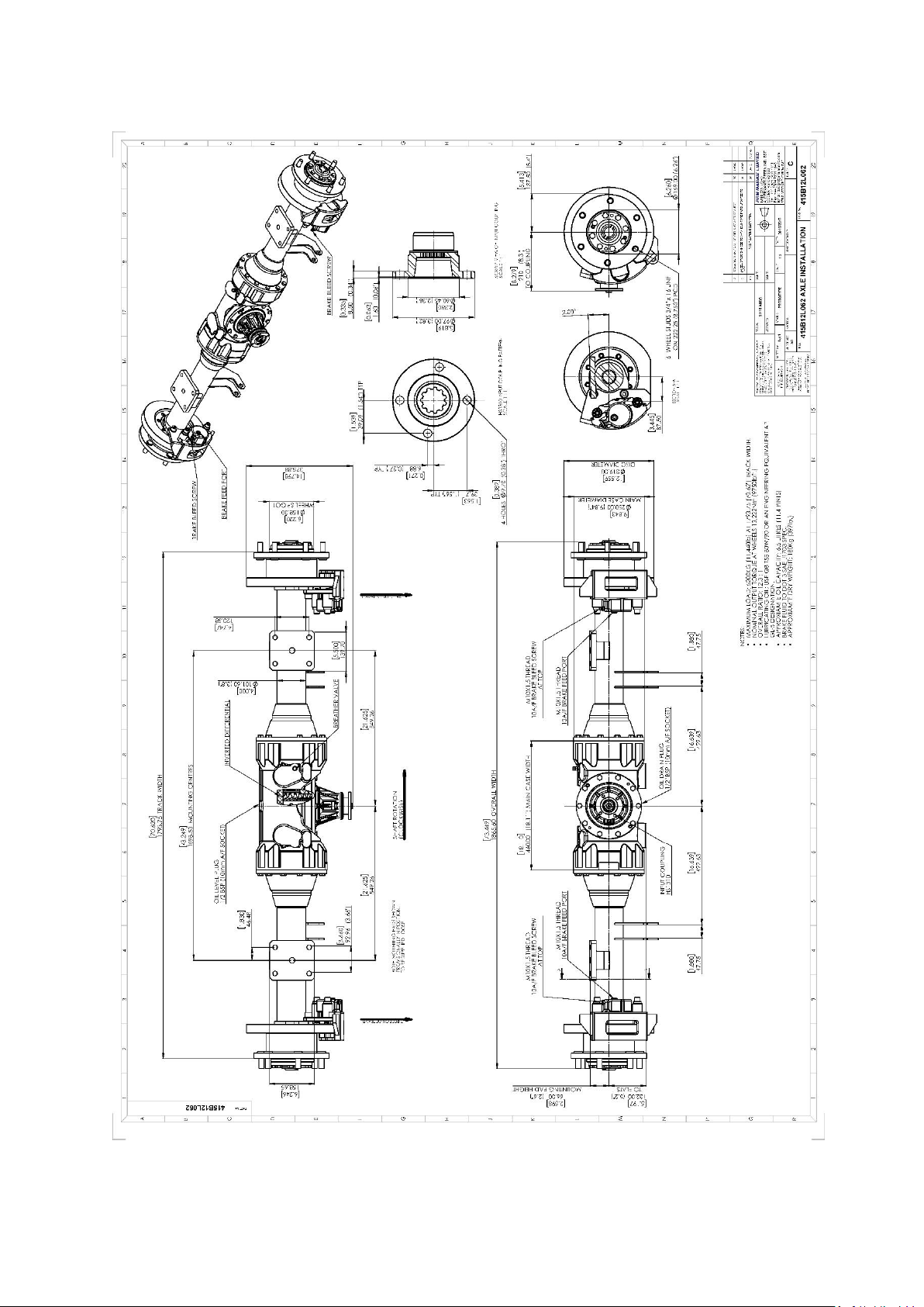
Installation Drawing
6
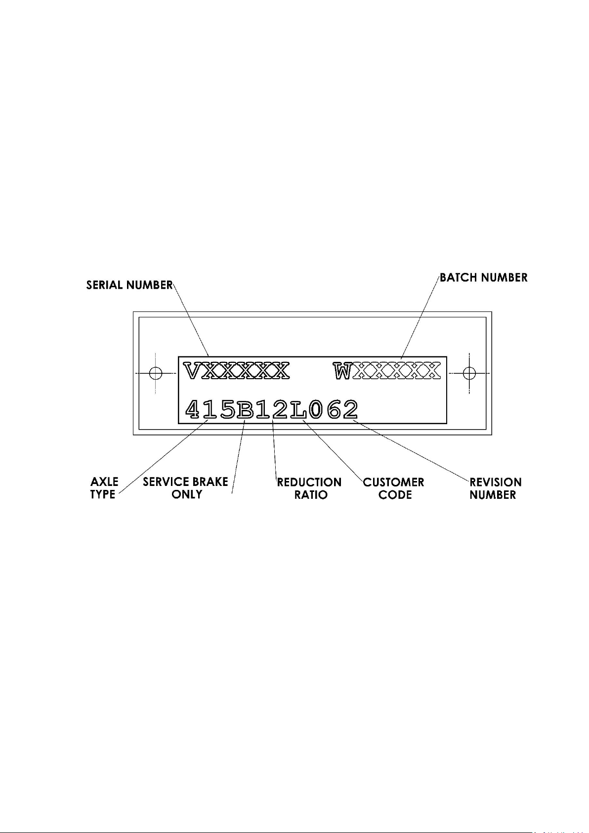
IDENTIFICATION
If spares are required, please quote the axle model, the vehicle/machine model and serial number
from the blue plate. 415 Axles are produced in a variety of configurations for individual customer
requirements; therefore, it is important to identify the Axle correctly.
The part number allocated to each Axle describes the basic specification as below:
7

GENERAL SERVICE INFORMATION
Check
Frequency
Axle Oil change
After initial 300 Hrs
then every 1,000 Hrs
Axle Oil Level check
Monthly
Axle Shaft Bolts
Monthly
Brake Fluid change
Annually
Brake Fluid Level check
Monthly
Check Axle Arm/Main Case joint securing Bolts
Monthly
Check Wheel Hub Bearing adjustment
1,000 Hrs
Check Wheel Nut
Weekly
Visual check for oil leaks around joints and Seals
Weekly
Prop Shaft Bolts
Monthly
Routine Maintenance
Lubricants
Only those lubricants shown below, or their direct equivalents must be used:
SAE 80W-90 Gear oil for operation in ambient temperatures
between 0°C and 30°C (32°F -86°F)
NOTE: An alternative engineering approved Gear oil may be used. Consult ‘PRM Newage’ before
filling the axle.
The oil is added via the combined Filler/Level Plug positioned on the rear of the axle Main Case.
When installing new Unitized Hub Seals, ensure the outer surface of the seal and the inner diameter
bore of the Hub is free from grease. Use Loctite SF7063 Solvent Cleaner to degrease both before
fitment of the seal.
Greases
Smear grease between Oil Seal lips and ‘O’ Rings at major overhauls (with exception to the Wheel
Hub seals), or whenever a repair to these areas is performed.
Only those greases shown below, their direct equivalents or alternative engineering approved grease
must be used: Texaco Multifak EP2
Brake Fluid
The Axle Brakes operate with the fluid specification: FMVSS 116 DOT 4, SAEJ1703 and ISO4925 Brake
Fluid
NOTE: An ISO VG32 Mineral Hydraulic Fluid Should NOT be used under any circumstance.
Liquid Sealant
The Main Case/Axle Arm joint faces must be sealed with either of the following:
• Threebond 1207D Silicone Liquid Gasket
NOTE: An alternative engineering approved silicon sealant may be used.
For locking features, the following compound must be used:
• Loctite 243
NOTE: An alternative engineering approved locking compound may be used.
8

Fastener Tightening Torques
Fastener
A/F
(mm)
Torque (Nm.)
Torque (lb.
Ft)
Across
Flats
Newton Me-
tres
Pounds
Force Feet
Main Case Assembly
Axle Arm/Main Case High Tensile Bolts (M12)
19
146
107
Axle Shaft/Wheel Hub High Tensile Bolts (M12)
19
146
107
Brake Calliper mounting Grade S Cap Bolt (M16)
14
230
170
Calliper Carrier Cap Bolts (M16)
14
257
190
Differential assembly Nut (M10)
17
77
57
Pinion Housing Bolt (M10)
17
84
62
Drain and Level Plug (1/2” BSP)
10
16
12
Hub Assembly Lock Nut (M65) – (Special Tool
required TMFS13)
---
135
100
Input Drive Flange Drag Torque after collapsing
Spacer
30
1.92/2.48
17/22 lbin
Assembly
Pinion/Wheel
Drive Flange
P.C.D
Backlash
416-9820
416-2000
416-2010
415-9810 (415-
2180 & 250-
0910)
(HS 1310)
79.40mm
(3.125”)
0.22-
0.30mm
(0.009-
0.012”)
Axle Backlash
Tooling
The following tooling is used to aid in the servicing of the axle. These are available from the Original
Equipment Manufacturer.
TMFS13 Socket Spanner for Wheel Hub Bearing Lock Nut 010N651. The TMFS13 tool is available
from SKF stockists (M65 Stub Axle Locknut socket 19mm (3/4”) drive)
9
 Loading...