

Page 1
NAME: Pro Stage 348
MODEL: PR-8920
This product manual contains important inform ation about the safe installation and use of this lighting fixture.
Please read and follow these instructions carefully and keep this manual in a safe place for future reference.
PR LIGHTING L TD.
http://www.pr-lighting.com
Page 2
2/14
INDEX
SAFE USAGE OF THE LIGHTING FIXTURE…………………………………………………………………. 2
INST ALLING THE LIGHTING FIXTURE……………………………………………………………………... 4
CONTROL SYSTEM AND POWER CONNECTIONS………………………………………………………..... 4
DMX TERMINA TOR………………………………………………………... ……………………………...... 5
SETUP OPTIONS- LIGHTING FIXTURE CONFIGURATION…………………………………………………. 5
TO SET THE DMX STAR T ADDRESS………………………………………………………... ……………… 6
OPERA TION MENU………………………………………………………... ……………………………....... 7
DMX PROTOCOL………………………………………………………... ……………………………......... 7
INDICA TION OF LED DISPLAY……………………………………………………….................................... 8
MAINTENANCE………………………………………………………............................................................. 8
TROUBLESHOOTING………………………………………………………..................................................... 8
TECHNICAL DATA………………………………………………………......................................................... 9
ELECTRICAL DIAGRAM………………………………………………………............................................... 11
COMPONENT ORDER CODES………………………………………………………...................................... 12
BACK COVER………………………………………………………................................................................ 14
Please note that as part of our ongoing commitment to continuous product development, specification s are subject to
change without notice. Whilst every care is taken in the preparation of this manual we reserve the right to change
specifications in the course of product improvement. The publishers cannot be held responsible for the accuracy of the
information herein, or any consequence arising from them.
Every unit is completely tested and properly packed by the manufacturer. Please make sure the packing and / or the unit are in good condition before
installation and use. Should there be any damage caused by transportation, consult your dealer and do not use the unit. Any damage caused by improper
use will not be assumed by the manufacturer and / or dealer
ACCESSORIES
These items are packed together with the lighting fixture
Name Quantity Unit Remark
Safety cord 1 Pc
User’s Manual 1 Pc
Clamp 1 Pc
SAFE USAGE OF THE LIGHTING FIXTURE
When unpacking and before disposing of the carton, check there is no transportation damage
before using the lighting fixture. Should there be any damage caused by transportation,
consult your dealer and do not use the apparatus.
Please make sure that a lighting fixture's cover mustn't be tightened fully for allow
ance for some movement, otherwise, it will be expanded after heated resulting in the
fixture not being used normally.
Page 3

3/14
The lighting fixture can be only used indoors, IP20.
The lighting fixture is not designed or intended to be mounted directly on to inflammable surfaces.
The lighting fixture is only intended for installation, operation and maintenance by qualified personnel.
Do not project the beam onto inflammable surfaces, minimum distance is 5m.
5m
A void direct exposure to the light from the lamp. The light i s harmful to eyes.
Do not attempt to dismantle and/or modify the lighting fixture in any way .
Electrical connection must only be carried out by qualified personnel.
Before installation, ensure that the voltage and frequency of power supply match the power requirements of the lighting fixture.
It is essential that each lighting fixture is correctly earthed and that electrical installation conforms to all relevant standards.
Do not connect this device to any other types of dimmer apparatus.
Make sure that the power-cord is never crimped or damaged by sharp edges. Never let the power-cord come into contact with other cables.
Only handle the power-cord by the plug. Never pull out the plug by tugging the power-cord.
When the lighting fixture is hanged to a high place, please use a safety cord provided to pass through the lighting fixture’s handles as a
secondary safety fixing for safety seasons. For details, refer to “INSTALL THE LIGHTING FIXTURE “section.
Exterior surface temperatures of the lighting fixture after 5 minutes operation is 45℃, when achieving steady state it is55℃.
There is no user serviceable parts inside the lighting fixture, do not open the housing and never operate the lighting fixture with the
covers removed.
If you have any questions, don’t hesitate to consult your dealer or manufacturer .
Always disconnection from power, when the device not in use or before cleaning or any maintenance
work !
Page 4
4/14
INST ALL THE LIGHTING FIXTURE
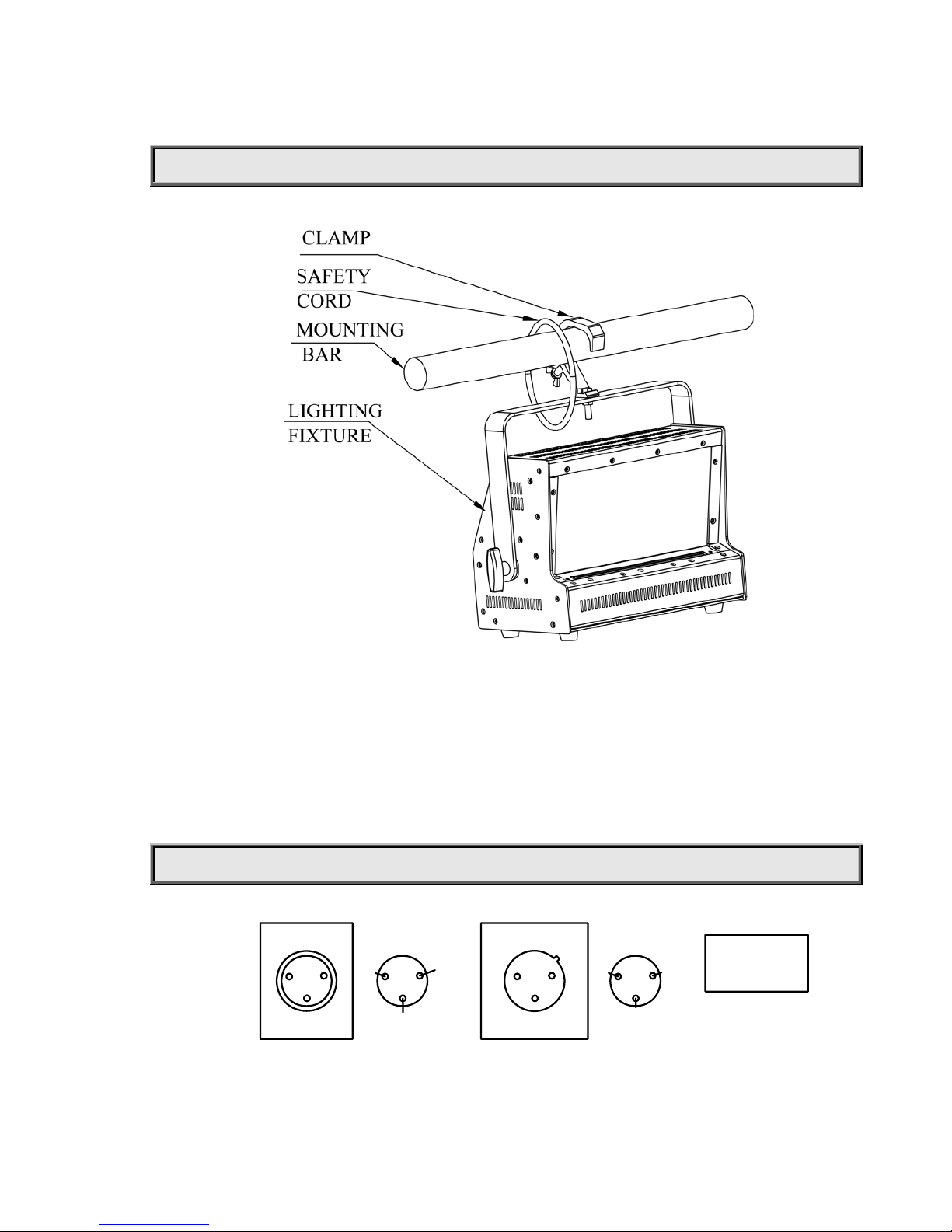
When the lighting fixture is used, put it on a flat surface or hang it. Make sure it is steady and secured.
When the lighting fixture is used at a high place, as the figure above, move the support to the top of the lighting fixture, connect a lamp
hook to the mounting hole reserved in the support by screws, and then hang the hook to mounting bar. Eventually, use the safety cord
provided to pass through the support and hang it as a second safety fixing.
CONTROL SYSTEM AND POWER CONNECTION
DMX 512
2
DATADATA+3
1
GND
FUNCTION
PIN
三芯
DMX OUT
DMX IN
2
1
3
2
1
3
THREE-PIN
Connection between the controller and a lighting fixture and between one lighting fixture and another must be made with a 2
core-screened cable, with each core having at least a 0.5mm diameter. Please use the li ghting fi xture’s cannon 3- pin signal input and
output cables as connection. The 3-pin signal connections are connected as shown in the figure above.
Page 5
5/14
Note: Care should be taken to ensure that none of the pins touch the metallic body of the plug or each other. The body of the plug is not
connected in any way . The device accepts digital control signals i n protocol DMX512 (1990).
Maximum 32 units can be connected in series by 3-pin signal cable. Connect the controller’s output to the first fixture’s input, and
connect the first fixture’s output to the second fixture’s input and connect the rest fixtures in the same way. Eventually connect the last
fixture’s output to a DMX terminator as shown in the figure below .
Note: For synchronous control, Start Addresses for all slave units must be same.
Each unit’s POWER INPUT should be connected to external POWER individually and the voltage and frequency of the power
supplied match what its nameplate describes.
. DMX TERMINATOR
In the Controller mode, at the last fixture in the chain, the DMX output has to be connected with a DMX terminator. This prevents
electrical noise from disturbing and corrupting the DMX control signals.
The DMX terminator is simply an XLR connector with a 120Ω (ohm) resistor connected across pins 2 and 3, which is then plugged
into the output socket on the last projector in the chain. The connections are illustrated below.
2
1
3
120
DMX TERMINATOR
CONNECTION
Connect a 120 (OHM) resistor
across pins 2 and 3 in an XLR plug
and insert into the DMX out socket
on the last unit in the chain.
PIN 3
PIN 2
SETUP OPTIONS-LIGHTING FIXTURE CONFIGURATION
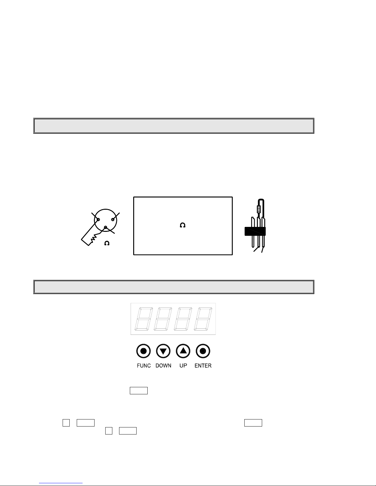
Lighting fixture configuration can be set conveniently via push-button switch and LED display .
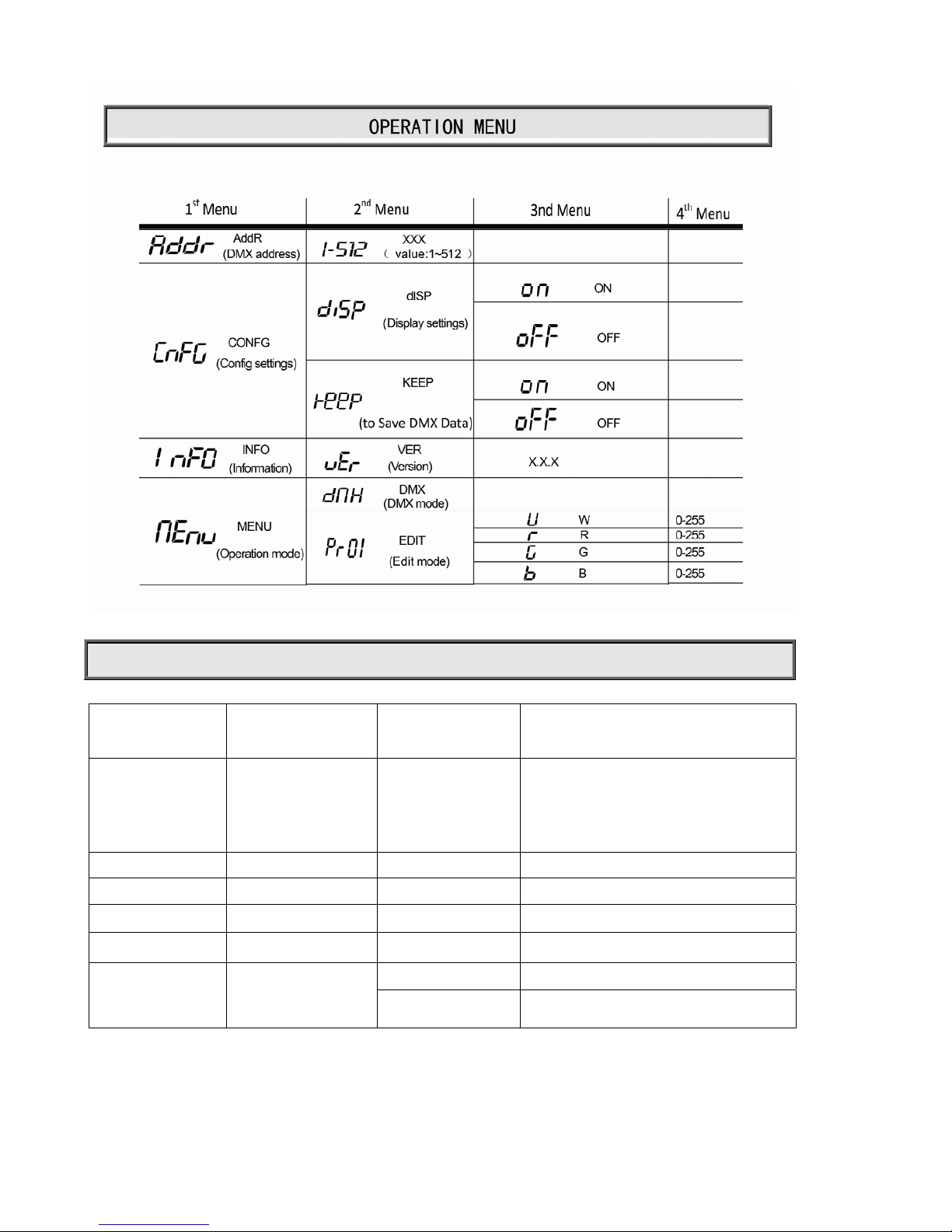
Launch the lighting fixture and press button ENTER for more than 5 seconds to unlock the panel, the LCD will show the function
menu of the lighting fixture, each main menu has its submenus and each submenu has a specific function. For details, please see
the “OPERATION MENU” section.
Press button UP or DOWN if you want to browse through the various Setup Options. Press button ENTER to save your settings or
enter the next menu. Press button UP or DOWN to change values(plus or minus)
Page 6
6/14
Press button FUNC, it will return to the upper menu one by one or browse through the main menu.
TO SET THE DMX STAR T ADDRESS
Each device must be given a DMX start address so that the correct lighting fixture responds to the correct control signals. This DMX
start address is the chann el nu mber from wh ich the ligh ting f ixtur e start s to “ listen” to the d igi tal con trol in forma tion be ing sent out
from the controller. The device has 6 channels, so set the No. 1 lighting fixture’s address 001, No. 2 lighting fixture’s address 007,
No. 3 lighting fixture’s address 013, No. 4 lighting fixture’ s address 019, and so on.
Launch the lighting fixture. Press button ENTER for more than 5 seconds to unlock the panel.
Press button FUNC, UP or DOWN to find “AddR” menu.
Then press ENTER to show DMX address and press UP or DOWN to set DMX address.
At this time, the address will flash continuously. Press button ENTER to confirm and it means the setting has been
enabled and saved. After powered next time, the latest setting will be used.
Press button FUNC, it will return to the upper menu one by one.
Page 7
7/14
DMX PROTOCOL
CHANNELS FUNCTION DMX DESCRIPTION
1 Dimmer 000-255 Linear Dimming from dark to light
2 White 000-255 Linear Dimming from dark to light
3 Red 000-255 Linear Dimming from dark to light
4 Green 000-255 Linear Dimming from dark to light
5 Blue 000-255 Linear Dimming from dark to light
0 No effect
6 Strobe
001-255 Strobe speed from slow to fast
Page 8
8/14
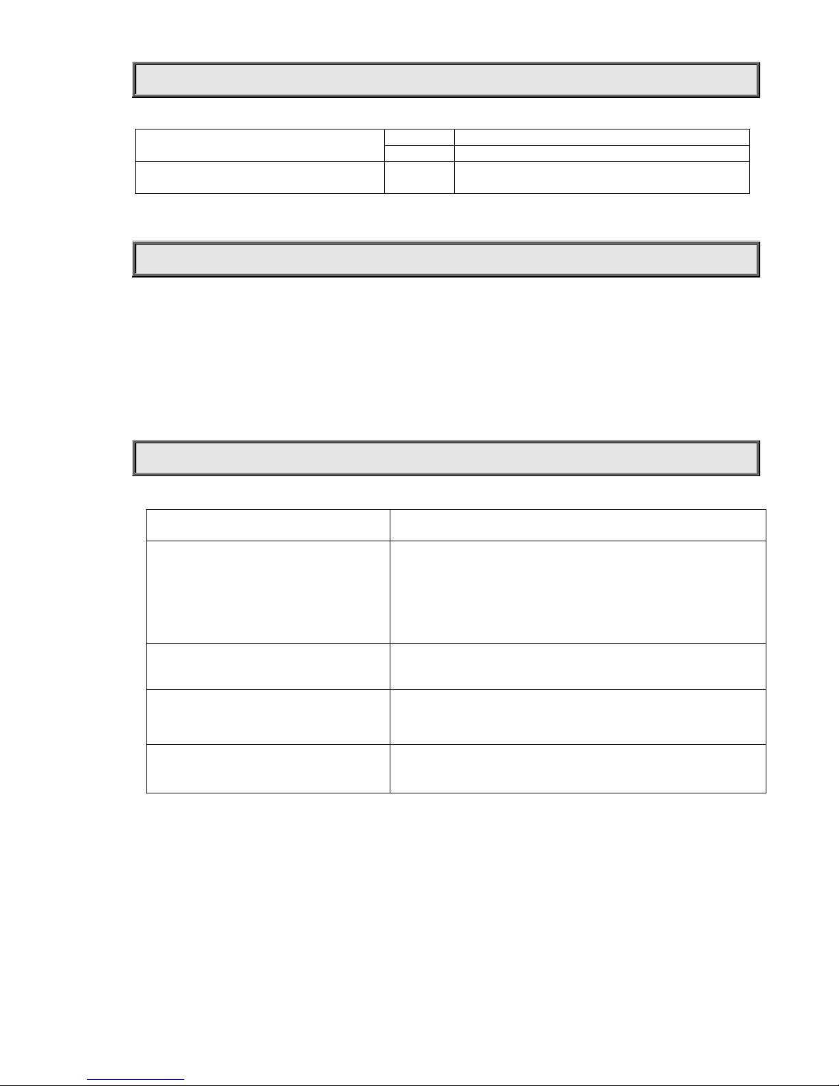
INDICATION OF LED CHARACTER
On DMX signal OK
DMX Indication
Off No DMX signal
Display Information
Flash Parameter or Value not saved, please press
ENTER T to save
MAINTENANCE
To prolong the life of the lighting fixture, it is very important to do the maintenance work. Cooling fans must be cleaned once every
15days and external lens cleaned periodically for an optimum light output. DO NOT USE ANY SOLVENT CONTAINING
CHEMICAL ELEMENT .
Cleaning frequency depends on the environment in which the fixture operates. Soft cloth and typical glass cleaning products should be
used for cleaning with care. It is recommended to clean lighting fixture at least once every 20 days.
Do not use any organic solvent, e.g. alcohol, to clean housing of the apparatus.
TROUBLESHOOTING
PROBLEM ACTION
The lighting fixture doesn’t switch on
¾ Power connection is not correct.
¾ Power supply is damaged or abnormal. Call a qualified personnel to fix
it.
¾ Connection of control board is not correct. Call a qualified personnel to
fix it.
The lighting fixture can be turned on, but LEDs
do not emit light and are out of control.
¾ Connection of LED board is not correct. Call a qualified personnel to fix
it.
The lamp comes on but the lighting fixture
doesn’t respond to the controller
¾ Make sure that the lighting fixture’s Start Address is property set..
¾ Replace or repair the XLR signal cable.
The beam appears dim ¾ The lighting fixture is too hot. T ake ventilation measures to make it cool.
Page 9

9/14
TECHNICAL DATA
VOLTAGES:
100-240V AC,50/60Hz
POWER CONSUMPTION:
100W
LED:
Quantity
48
(R:12+G:12+B:12+W:12)
Manufacturers Rated LED Life 50000 Hours
COLOURS:
RGBW linear color mixing with Macro
COLOR TEMPERA TURE CORRECTION:
Linear color temperature correction from 3200K to 10000K
DIMMER:
0-100% linearly adjustable
Light Source Luminous Flux
2100 lm
STROBE:
Electronic Strobe 0 ~25F.P.S
LIGHT ANGLE:
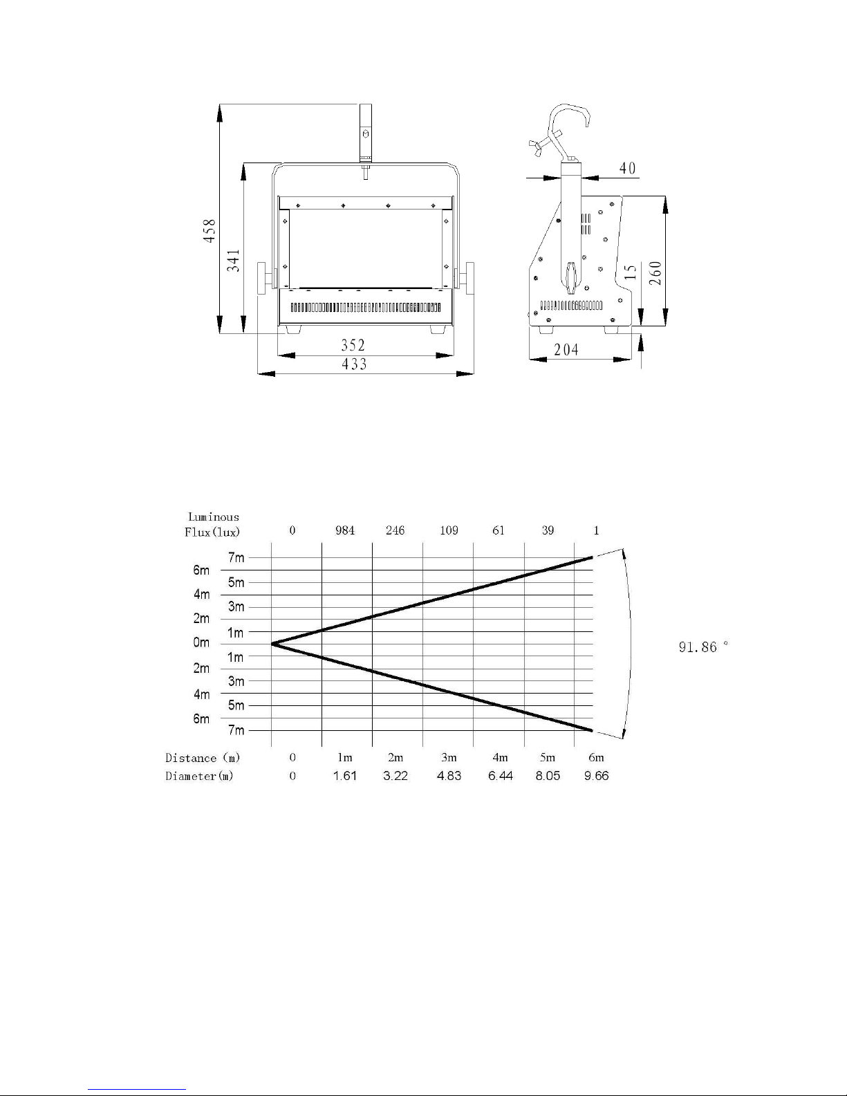
Field Angle(
1/10 Maximum) θ
horizontal direction 0°~1 18° vertical direction 0°~92°
CONTROL:
DMX512, 3 pin interfaces
6 channels in standard mode,
HOUSING:
High Te nsile Extruding Aluminum, IP20
WORK ENVIRONMENT TEMPERATURE:
-20°C~40°C
WEIGHT:
Net Weight: 7Kg Gross Weight: 9Kg
Page 10
10/14
Light Output (vertical direction)
SIZES:
Page 11
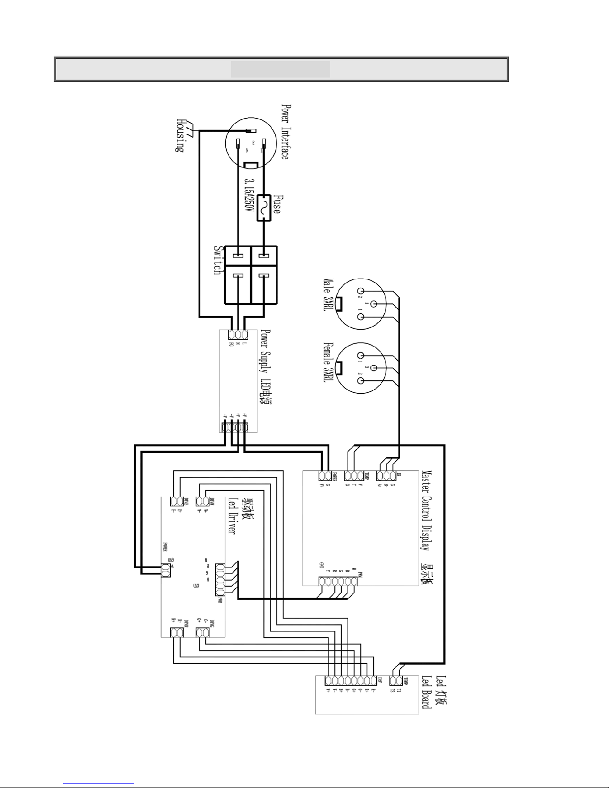
11/14
Electrical Diagram
Page 12
12/14
COMPONENT ORDER CODES
NAME PART NO. QUANTITY REMARK
3-PIN CONTROL CABLE 242810033 1 5m
200W POWER SUPPLY 190010122 1 K18N-UP200S58
LAMP BOARD 230060162 1 RGBW 48*3W
MAIN CONTROL BOARD 230060171 1
LED 4 CHANNEL DRIVER BOARD 230060174 1
Page 13

13/14
Page 14

14/14
PR LIGHTING LTD.
PR N ew H i-t ech Science Park, 1582 Xingye Avenue
Nancun Panyu, Guangzhou, 511442 China
TEL: +86-20-3995 2888
F AX: +86-20-3995 2330
P/N: 320020131
Version: 20130513
 Loading...