

Page 1
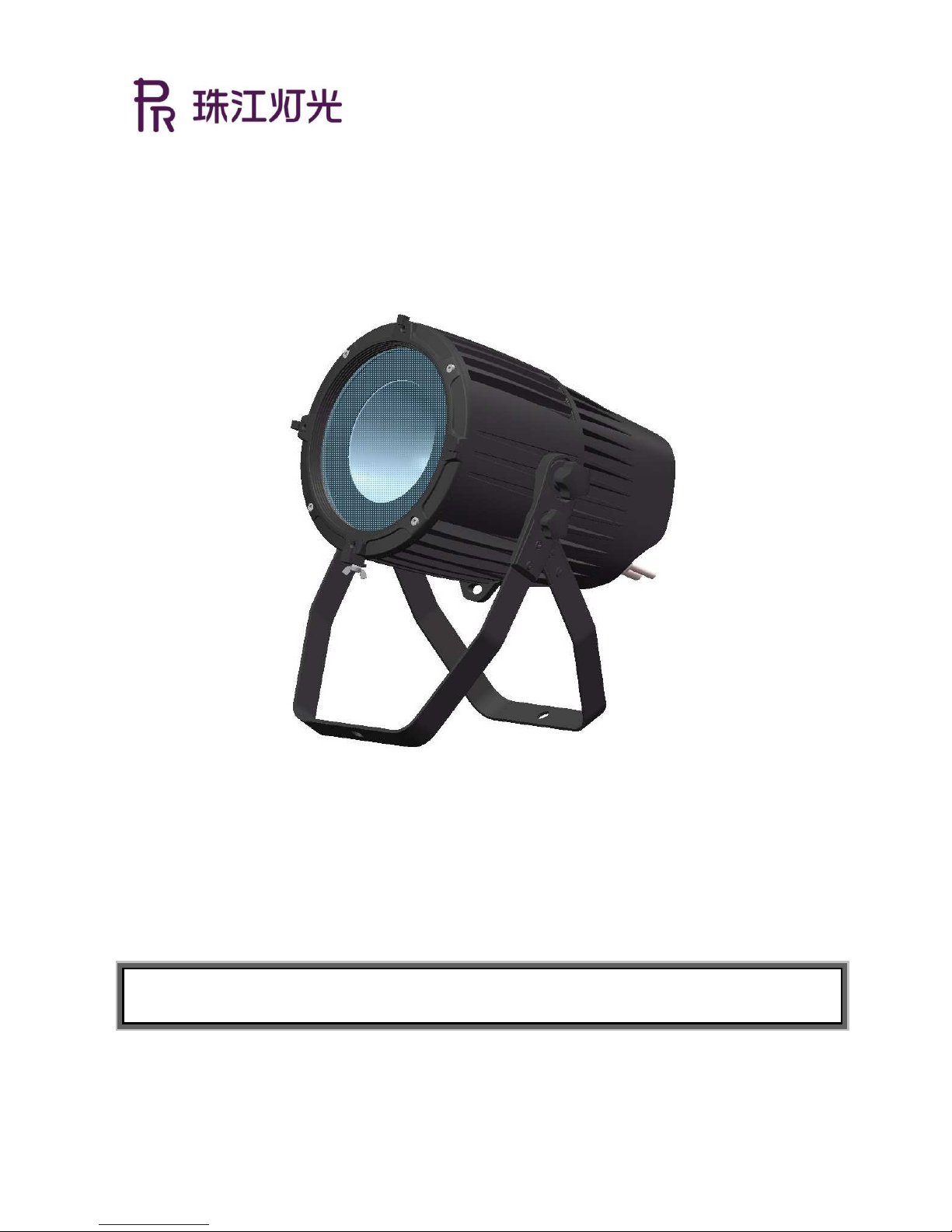
XPar 150
PR-8202
The user manual contains important information about the safe installation and use of a projector. Please read
and follow these instructions carefully and keep the manual in a safe place for future reference.
PR LIGHTING LTD.
http://www.pr-lighting.com
Page 2

INDEX
1.
SAFETY AND WARNINGS……………………………………………………………………………………………………
2.
INSTUCTIONS …………………………………………………………………………………………………………………
●CLEANING AND MAINTENANCE …………………………………………………………………………………………
●TROUBLESHOOTING…………………………………………………………………………………………………………
3. APPEARANCE …………………………………………………………………………………………………………………
4. INSTALLATION ………………………………………………………………………………………………………………
●RIGGING ………………………………………………………………………………………………………………………
●PLACE A UNIT ON A FLAT SURFACE………………………………………………………………………………………
●INSTALLATION OF BARN DOOR……………………………………………………………………………………………
●TRANSPORTATION……………………………………………………………………………………………………………
●POWER CONNECTIONS ……………………………………………………………………………………………………
●DMX CONTROL CONNECTION ……………………………………………………………………………………………
●DMX TERMINATOR …………………………………………………………………………………………………………
5. SETUP AND CONFIGURATION………………………………………………………………………………………………
●FRONT PANEL OPERATION…………………………………………………………………………………………………
●DMX START ADDRESS………………………………………………………………………………………………………
●DMX WIRELSESS CONTROL ………………………………………………………………………………………………
●STAND-ALONE MODE………………………………………………………………………………………………………
●MASTER/SLAVE MODE………………………………………………………………………………………………………
6.OPERATION MENU ……………………………………………………………………………………………………………
7. DMX PROTOCOL ……………………………………………………………………………………………………………
8.
TECHNICAL DATA………………………………………………………………………………………………………………
9.CIRCUIT DIAGRAM AND PCB CONNECTIONS……………………………………………………………………………
●CIRCUIT DIAGRAM …………………………………………………………………………………………………………
●PCB CONNECTIONS…………………………………………………………………………………………………………
10.COMPONENT ORDER CODES ………………………………………………………………………………………………
1
2
2
2
3
4
4
4
4
5
5
6
6
7
7
7
7
7
7
8
9
11
13
13
14
15
ACCESSORIES
The following items are supplied with the projector and please check:
Name Quantity Unit Remark
G clamps 1 Pc
Power cord 1 Pc With plug and socket
XLR Cable 2 Pc
Safety cord 1 Pc
User manual 1 Pc
Transparent Cover+ seal+ screws ×6 1 Set Optional
Barn Door 1 Set Optional
Frost panel(Barn Door + Frost panel) 1 Set Optional
Please note that as part of our ongoing commitment to continuous product development, specifications are
subject to change without notice. Whilst every care is taken in the preparation of the manual we reserve the
right to change specifications in the course of product improvement. The publishers cannot be held responsible
for the accuracy of the information herein, or any consequence arising from them.
Every unit is tested completely and packed properly by the manufacturer. Please make sure the packing and /
or the unit are in good condition before installation and use. Should there be any damage caused by
transportation, consult your dealer and do not use the unit. Any damage caused by improper use will not be
assumed by the manufacturer and / or dealer.
Page 3
1
1. SAFETY AND WARNINGS
.
NOTE
Before a projector’s installation, power-on, operation and maintenance, please carefully read
the safety information hereinafter!
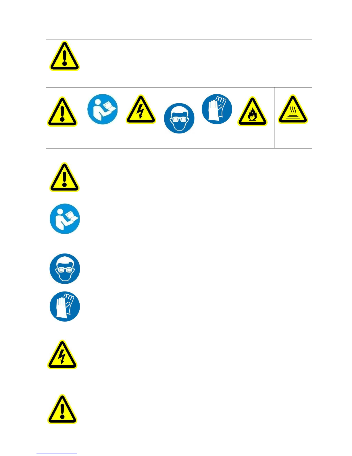
The following safety signs are used in the user manual.
Warning
User
Manual
Electrical
shock
Goggles
Protective
Gloves
Flames
High
Temperature
● When unpacking , check if there is transportation damage before using the projector. Should there be
any damage caused by transportation, consult your dealer and do not use it.
●The manufacture is not responsible for loss caused by the user not following the manual or changing the
projector as he/she likes
●Please be noted that the damage caused by changing the projector at will is not warranted.
● Do not hesitate to contact the dealer or the manufacturer if any questions or advice.
● Use only in dry locations. Keep this unit away from rain and moisture, excessive heat, humidity and dust. Do not
allow contact with water or any other liquids.
●The projector should be kept away from high temperature, fire, electrical surge, vibration and strong light while
being operated
●The projector is only intended for installation, operation and maintenance by qualified personnel. And the
operation must strictly follow the procedures in the manual
●No repairable parts in the projector and do not open covers for maintenance by yourself.
●Don’t look straightly into the light sources especially for epileptics, otherwise eyes will be burned.
●Do not connect this device to any type of dimmer pack
●After lamp switched on, the minimum distance between the projector and illuminated surface is 10m
●lens and other optical parts shall be replaced immediately if they have deformed or been damaged, otherwise the
light output will be compromised.
●Before operation, please confirm that all covers(housing) are on and screws tightened. It’s forbidden to use a
projector while covers(housing)are off
●Keep the lamp clean and do not touch it with bare hands.
●While operating it, wear protective items.
●Any electrical connection must be carried out by a qualified person .
●Before installation, please confirm the voltage supplied matches what is required for the projector
●Each projector must be properly earthed and installed as per related electrical standards.
●Do not use power cord with its insulator damaged and connect the power cord with other cables.
●If the projector is not used or under cleaning,, please hold the plug and unplug it. Do not unplug it forcefully or
by pulling the power cable.
●All power cords must conform to related safety and regulations
●While being operated, the projector should not be under rains or in humidity.
●Do not switch on and off the projector constantly in very short intervals, otherwise the light source’s and other
electrical parts’ life will be shortened .
●There are safety cord holes at the bottom of the base of a projector. In view of safety, please run the safety cord
supplied through the safety cord holes for safety support.
●Before any installation, maintenance and cleaning work, please ensure the projector is disconnected from power
mains.
Page 4
2
●After running for 5minutes at constant temperature environment, the temperature of the housing of the
projector is 45℃.After stable operation , its temperature is 50℃.
●While the lamp is stricken for the first time, there will be smoke and strange smell. It’s normal and does not
mean the projector has some defects.
●While operated, do not touch the metallic housing. It is very hot during operation.
●Do not mount the projector directly on inflammable surface.
●Do not project the beam straightly on combustible items and the minimum distance between the projector
and illuminated items is 10m.
●A projector should be installed with good ventilation and the minimum distance between the projector and
walls is 50cm. At the same time, please ensure the fans and air inlets and outlets are workable.
2. INSTRUCTIONS
●CLEANING AND MAINTENANCE
The accumulation of oil, smoke and dust on the lens will compromise the light output. Cleaning a projector is very necessary to ensure
a reliable use of it. Without the permission by a qualified person for internal part replacement, it is forbidden to dismantle a unit.
Cleaning frequency is to be decided by operations and its environment. Use soft cloth and normal detergent for glass for cleaning work.
It’s advised external optical system be cleaned every 20days. Keep lens clean and do not touch optical parts with bare hands.
●Before any maintenance and cleaning, please ensure the project is off the power
●Only qualified person is allowed to do maintenance
●During maintenance and before maintenance, the projector must be off power.
●To avoid internal damage, sun light or other light mustn’t penetrate into the projector via front lens whether
it runs or not
●Do not use alcohol or other organic solvent to clean the housing to avoid damage.
●Do not use any solvent with chemical elements to clean color filters or hot mirror.
●TROUBLESHOOTING
PROBLEM ACTION
The projector doesn’t switch on
Check the fuse on the power socket.
Check the lamp.
The lamp is on but the projector doesn’t respond
to the controller
Make sure that the fixture’s start address is right
Replace or repair the XLR signal cable.
The projector functions intermittently Make sure the fan is working well or fans and their shields are not blocked
Beam appears dim, Low in brightness
Make sure the lamp is within its lifespan
Remove dust or grease from the lenses.
The project image appears to have a halo Carefully clean the lamp, optical lenses and other components.
Heavily Defective Beam
Check if lens are in good condition(not cracked)
Clean dust or grease on the lens.
Page 5
3
3. APPEARANCE
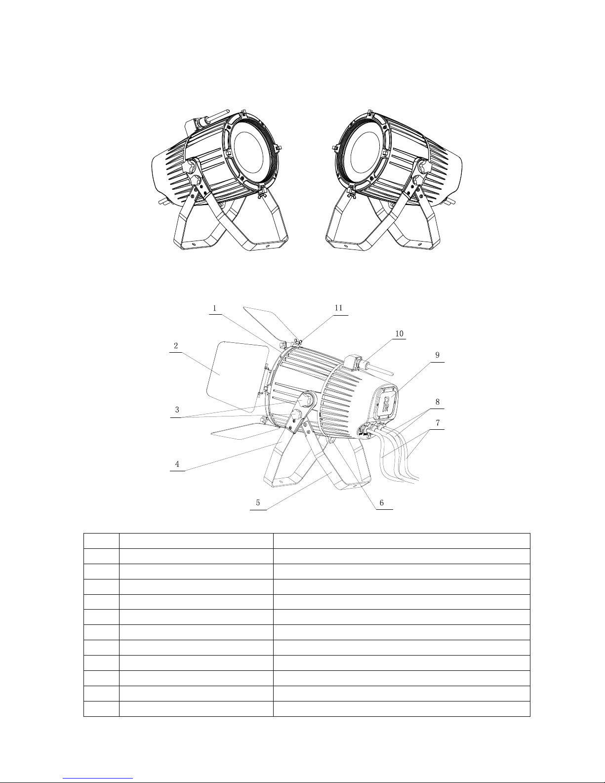
(The unit has two different settings. One is with wireless control function and the other version without it. After either
version leaves the factory, they can’t be changed in between as you like)
With wireless control function Without wireless control function
Product’s External Functional Sketch:
No.
Name Remarks
1
Frost panel(Optional)
Other components should be selected if frost panel selected
2
Barn Door (Optional)
3 Knob
4 Arm
5 Support
6 Safety cord hole
7 XLR cable Small
8 Power Cord Big
9
Transparent Display Cover(Optional )
Used in harsh environment like dusty area or being under water
10 Wireless Antenna Only Supplied with the version with Wireless control function
11 Butterfly screws Installation and dismantlement of barn door
Page 6
4
4. INSTALLATION
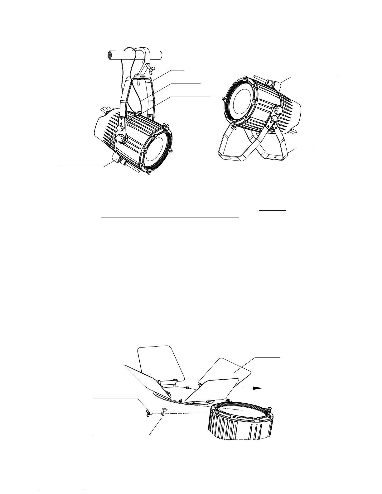
●RIGGING
Before moving the unit, lock the adjusting knob.
Take 1 clamps and the safety cord out from the package and mount 2 clamps on the underside of fixture with 2 retainers attached to
each clamp. Hang the fixture on the structure and fasten the screws attached to each clamp. (See the WARNING on the underside of
the base as shown above) To pass the SAFETY CORD through the HOLES for safety! Always ensure that the projector is firmly
anchored to avoid vibration and slipping whilst functioning. Always ensure that the structure that you are going to mount the projector
to is secure and strong enough to support the weight of the unit
(if the unit is without wireless control function, while being hung, the antenna should face down)
●PLACE A UNIT ON A FLAT SURFACE
Before placing a unit on a flat surface, loosen the small knob with the support and make the angle between the arm and the support
60degrees. Tighten the small knob. Loosen he big knob and adjust the angle between the arm and unit as desired and then tighten it.(If
the unit is with wireless control function, after the unit is placed on a flat surface the antenna should face up)
●INSTALLATION OF BARN DOOR
(Two different accessory options:a. Barn Door ;b. Barn door +Frost panel )
If only barn door, its installation is illustrated in the diagram below:
After loosening the butterfly screws(just loosen them, needn’t remove them) in the front of the head and rotating the holding
components in the shape of 7 by 90 degrees, place the barn door into the holding parts in the shape of 7. The installation is completed
after the holding components are rotated backwards , butterfly screws are tightened, and the safety cord with the barn door is run
through the hole in the middle of the head. The light closing effect can be reached by moving the barn door blades.
on flat surface with
antenna facing up
Support
Arm
Safety Cord
run through
safety cord hole
hung with antenna
facing down
butterfly screws
holding parts in the
shape of 7
Barn door
Place
Page 7
5
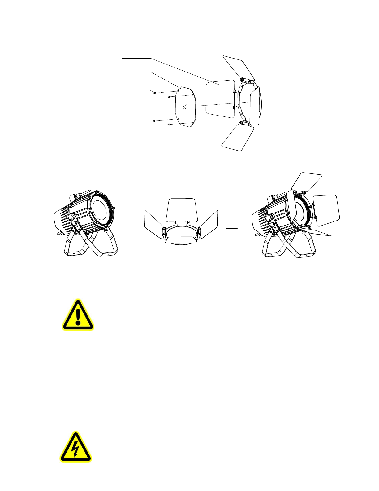
If the frost panel is also selected , it must be used in combination of the barn door. Its Installation and Dismantlement is
illustrated in the diagrams below:
The unit with a barn door is as follow:
●
TRANSPORTATION
Before transportation, tighten both knobs after the arm and support are overlapped.
WARNING:
●
The projector MUST be lifted or carried by the HANDLES instead of clamps.
●
.For safety the safety cord should afford 10 times the Projector’s weight.
●
POWER CONNECTION
Connect the power cord as follows:
L (live) =brown
E (earth) =yellow/green
N (neutral) =blue
Before power connection, please ensure the power supplied must match what the nameplate says. It is recommended that each
projector be connected with power separately so that they may be individually switched on and off.
Note: If projectors are connected in series, please connect POWERIN port of the 1st projector with the Power Mains, then connect its
POWER OUT with POWER IN of the 2nd projector, and so on till all fixtures are connected. If the voltage supplied is 200V-240V,
the maximum projectors connected is 8pcs, if it is 100V-120V, the maximum is 4pcs. The diameter of the cores of the wires for the
Power in/out cables must be equal or bigger than
2.5mm
2 .
●
The earth wire(yellow/green) must be connected to the ground. And electrical connection must be in
accordance with the standards concerned.
●
If any questions about the electrical installation, do not continue but consult a qualified electrician.
screws ×4
frost panel
barn door
Page 8
6
●
DMX CONTROL CONNECTION:
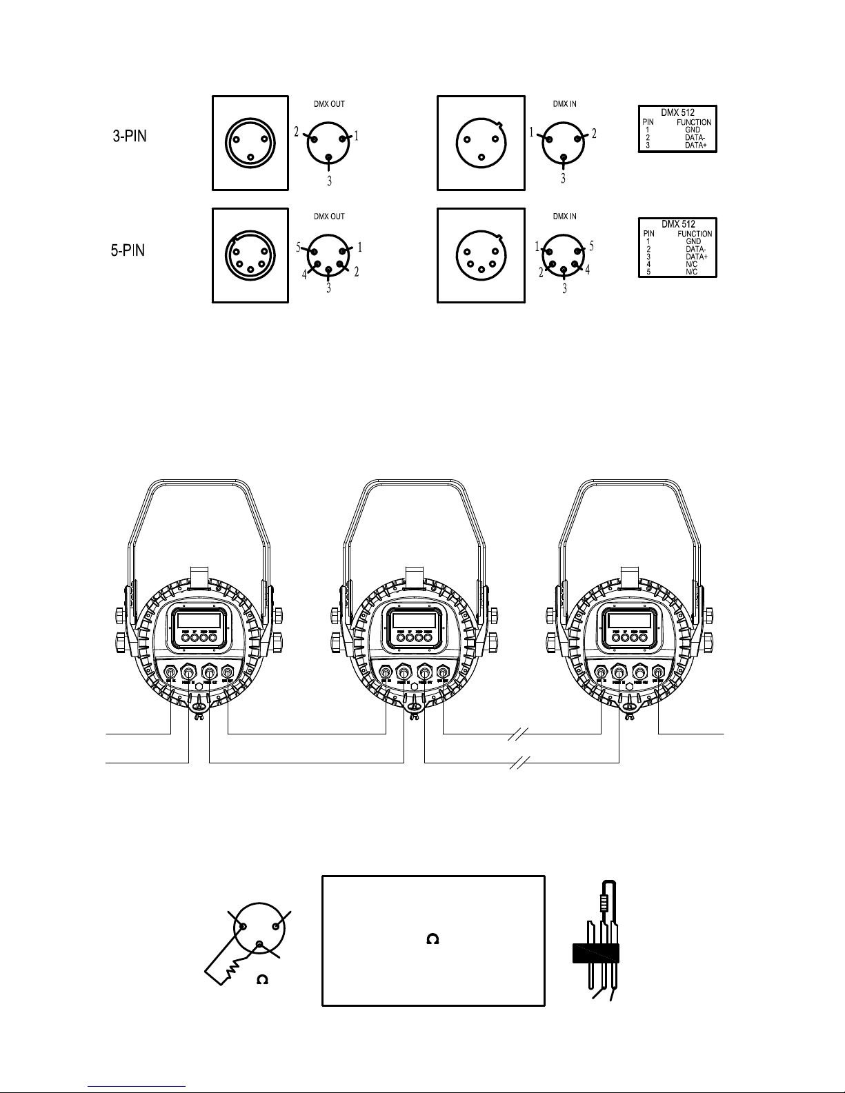
Connection between controller and projector and between one projector and another must be made with a twin-screened cable, with
each wire having at least a 0.5mm in diameter. Connection to and from the projector is via cannon 5 pin (which are included with the
projector) or 5 pin XLR plugs and sockets. The XLR's are connected as shown in the figure above.
Note: care should be taken to ensure that none of the pins touch the metallic body of the plug or each other. XLR plugs and sockets
mustn’t be connected in any way other than mentioned in the above figure. The unit accepts digital control signals in protocol
DMX512 (1990).
Connect the controller’s DMX output to the first fixture’s DMX input, and connect the first fixture’s DMX output to the second
fixture’s DMX input and connect the rest fixtures in the same way. Eventually connect the last fixture’s DMX output to a DMX
terminator as shown in the figure below.
●
DMX TERMINATOR
In the Controller mode, at the last fixture in the chain, the DMX output has to be connected with a DMX terminator. This prevents
electrical noise from disturbing and corrupting the DMX control signals.
The DMX terminator is simply an XLR connector with a 120Ω (ohm) resistor connected across pins 2 and 3, which is then plugged
into the output socket on the last projector in the chain. The connections are illustrated below.
POWER
DMX
CONTROLLER
DMX OUT DMX IN
POWER OUT POWER IN POWER OUT POWER IN
DMX OUT DMX IN
DMX
TERMINATOR
2
1
3
120
DMX TERMINATOR
CONNECTION
Connect a 120 (OHM) resistor
across pins 2 and 3 in an XLR plug
and insert into the DMX out socket
on the last unit in the chain.
PIN 3
PIN 2
Page 9
7
5. SETUP AND CONFIGURATION
●
FRONT PANEL OPERATION
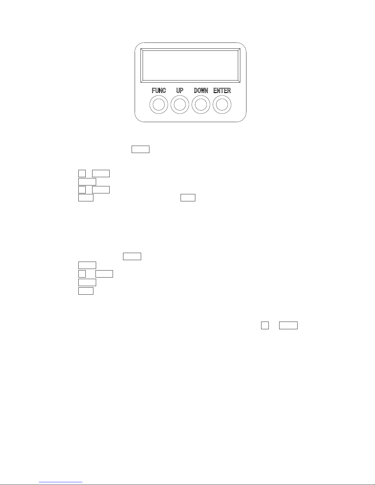
Projector configuration can be set conveniently via push button and LCD display.
Launch the projector and press button ENTER for more than 3 seconds to unlock the panel, the LCD will show the function menu of
the projector, each main menu has its submenus and each submenu has a specific function. For details, please see the
“OPERATION MENU” section.
Press button UP or DOWN if you want to browse through the various Setup Options.
Press button ENTER to save your settings or enter the submenu.
Press button UP or DOWN to change values(plus or minus)
Press button FUNC, it will return to the upper menu. If button FUNC not pressed, the default will show display status automatically.
●
DMX START ADDRESS
Each Projector must be given a DMX start address so that the correct projector responds to the correct control signals. This DMX start
address is the channel number from which the projector starts to “listen” to the digital control information being sent out from the
controller. The Unit has 2 DMX modes. There are standard mode and extended mode. For example standard mode has 6 channels,
so set the No. 1 projector’s address 001, No. 2 projector’s address 007, No. 3 projector’s address 013, No. 4 projector’s address019,
and so on.
Launch the projector. Press button ENTER more than 2seconds to unlock panel.
Press button ENTER to display DMX address;
Press button UP and DOWN, you can set the address;
Press button ENTER to confirm; after powered on next time, the default will be last value saved
Press button FUNC, it will return to the upper menu.
●
DMX WIRELESS CONTROL (If the projector has the function)
The projector has wireless control function with wireless receiver module and antenna for remote control.
The setup of it is below:
1. Enter into the projector’s menu. Select the menu “Config Settigns” via the bottoms of
UP and DOWN
2.
Select DMX control Mode---- Wireless First (Note: do not select XLR ONLY),then wireless indication in the
front panel will be on, meaning wireless control function is activated.
Only after the projector is linked with a transmitter, can it receive wireless signal sent by the transmitter. If unlinking it, Press
“Enter” for the menu of Unlink Wireless under the upper level menu of Config Settigns .
●
STAND-ALONE MODE
Operate the projector without connecting with a controller, enable the master mode through the operation panel, the
projector will run in Stand-Alone mode automatically.
DMX address can be set at any number within 512.
●
MASTER/SLAVE MODE
Many projectors can run synchronously in the Master/Slave mode by linking them with each other. First,
connect the first fixture’s DMX output to the second fixture’s DMX input using XLR-XLR control cable and then connect the second
fixture’s DMX output to the third fixture’s DMX input, and so on until all projector are connected in this way. Eventually connect the
last fixture’s DMX output to a DMX terminator. Set 1
st
projector as the master and others are Slaves.
Start Addresses of all Slaves are 001; Operation mode of the Master can be set any mode for a Master’ and Slaves’ operation mode can
be set accordingly.
After Powered on, the group will run in Master/Slave Mode
Page 10
8
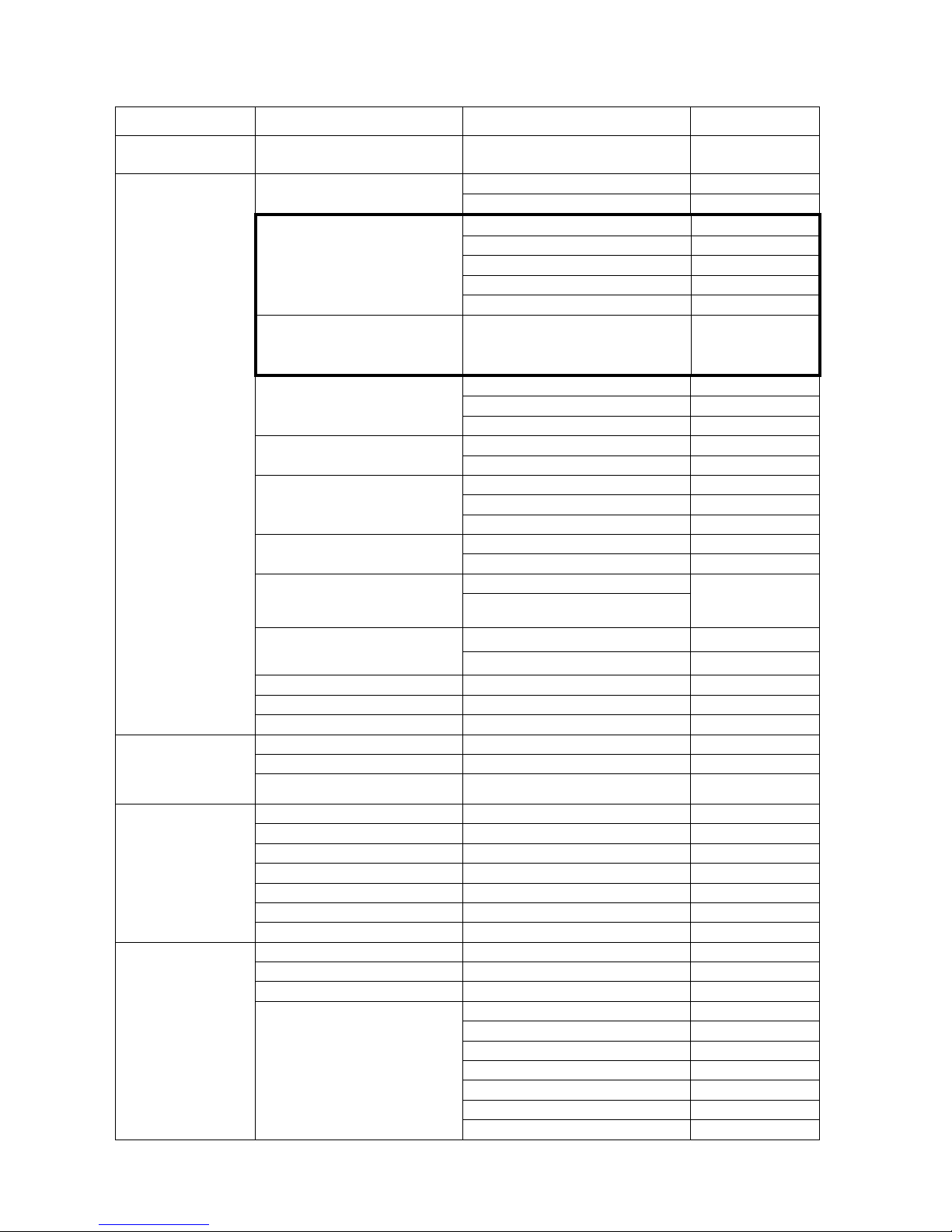
6. OPERATION MENU
(Those contents within the black box are only for the version with wireless control function)
1st level menu 2nd level menu 3rd level menu 4th level menu
DMX Address
Standard:001-506
Extended:001-501
Config Settings
DMX Channel Mode
(Default:STD6)
Standard 6
Extended 11
DMX Mode
(Default:XLR First)
(
The version without wireless
control does not have the function)
XLR First
XLR Only
Wireless Only
Wireless First
Wireless To XLR
Unlink Wireless
(
The version without wireless
control does not have the function)
Yes
LED OuptControl
(Default: No)
No
Brightness
Timer Control
Master/Slave
(Default:Slave)
Slave
Master
Color Offset
Red
128-255
Green
128-255
Blue
128-255
Language
(Default:English)
English
Chinese
Lcd Light Setup
On
Backlight off 3
minutes after no
button pushed
Off
Display Invert
Yes
No
Factory Settings Yes
Parameter Transm Yes
Clean Prgra Yes
Information
LED Temperature Display of Lamp board temperature
Fixture use Time Display of Fixture time
Software Ver.
X.X.X
Display of Software Version
Test Mode
Red
Green
Blue
White
RGB
RWB
RGBW
Operation Mode
DMX Mode Yes
User Memory Yes
Preset Memory(PR01~PR16)
User Progra Edit
(ET01~ET16)
Dimmer 0-255
Strobe 0-255
Red 0-255
Green 0-255
Blue 0-255
White 0-255
Keep Time 0-255
Page 11

9
Note:
1. In one DMX chain, only one unit can be made as the master. Before master works, unplug its XLR cable connected with the
console.
2. The parameters transmitted from the master include after several units are synchronized: DMX channel mode, display
settings(display contrast excluded),operation mode(including user memory).During parameter transmission, set the unit
transmitting data as master and others as slave
7. DMX PROTOCOL
Standard
mode
Extended
mode
Function DMX Description
1 1
Dimming 000-255 Linear Dimming 0%-100%
2
Color Temperature 000-255 Linear adjustment
3 Color Macros
000-016
No
017-024
White(10000K)
025-032
White(7200K)
033-040
White(5600K)
041-048
White(3200K)
049-056
Cyan
057-064
Yellow
065-072
Magenta
073-080
Red
081-088
Green
089-096
Blue
097-104
Light blue
105-112
Amber
113-120
Orange
121-128
Pink
129-255
Rainbow effect with speed from slow to fast between
2 4
Red 000-255 Linear change from light to dark
3 5
Green 000-255 Linear change from light to dark
4 6
Blue 000-255 Linear change from light to dark
5 7
White 000-255 Linear change from light to dark
6 8 Strobe
000-007
No
008-255
Strobe from slow to fast
9 Preset memory
000
No
001-015
Preset memory 1
016-031
Preset memory 2
032-047
Preset memory3
048-063
Preset memory 4
064-079
Preset memory 5
080-095
Preset memory 6
096-111
Preset memory 7
112-127
Preset memory 8
128-143
Preset memory 9
144-159
Preset memory 10
Page 12

10
160-175
Preset memory 11
176-191
Preset memory 12
192-207
Preset memory 13
208-223
Preset memory 14
224-239
Preset memory 15
240-255
Preset memory 16
10 User Memory
000
No
001-015
User Memory1
016-031
User Memory2
032-047
User Memory3
048-063
User Memory4
064-079
User Memory5
080-095
User Memory6
096-111
User Memory7
112-127
User Memory8
128-143
User Memory9
144-159
User Memory10
160-175
User Memory11
176-191
User Memory12
192-207
User Memory13
208-223
User Memory14
224-239
User Memory15
240-255
User Memory16
11 Preset Memory Speed
000-015
Speed 1, fastest
016-031
Speed 2
032-047
Speed 3
048-063
Speed 4
064-079
Speed 5
080-095
Speed 6
096-111
Speed 7
112-127
Speed 8
128-143
Speed 9
144-159
Speed 10
160-175
Speed 11
176-191
Speed 12
192-207
Speed 13
208-223
Speed 14
224-239
Speed 15
240-255
Speed 16, slowest
Note: DMX channel priority: Preset memory> user memory >Macros>RGBW dimming
While higher priority channels are in use, lower priority channels don’t work.
Page 13

11
8. TECHNICAL DATA
INPUT VOLTAGES: 100V~240V AC,50/60Hz
RATED POWER :200W@220V
LIGHT SOURCE SPECIFICATIONS:
Qty Single COB light source (RGBW)
Power Consumption 150W
Manufacturers Rated Lamp Life 50000hours
COLORS :
R/G/B/W linear color mixing with macros
DIMMING:
Linear Dimming from 0-100%
STROBE:
Electronic Strobe 0.5-33FP.S.
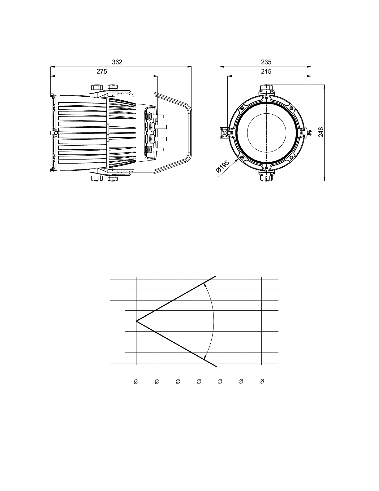
BEAM ANGLE:
Field Angle(1/10 peak): θ: 60°
Beam Angle(1/2peak) θ
1/2 :
30°
CONTROL:
DMX512, 3 pin interfaces
6channels in standard mode and 11channels in extended mode
Master/Slave Mode
3 Operation Modes(DMX Mode, Preset Memory, user Memory)
Test Mode
OTHER FUNCTIONS:
LED lamp board temperature and fixture time available in the menus
DMX channel mode and settings displayed
LCD and inverted display
Display backlight automatically shut off after delay
Parameters like operation mode and etc. transmitted under synchronization
HOUSING:
High tensile cast Aluminum alloy , IP67
NET WEIGHT: 6.5Kg
OPERATION TEMPERATURE:
-20°C~40°C
Page 14
12
SIZES:
LIGHT OUTPUT:
lux(RGBW)
lux(R)
lux(G)
lux(B)
lux(W)
60°
2669 667 297 167 107 740
649 162 72 41 26 180
1092 273 121 68 44 300
69 17 8
4
3 20
1019 255 113 64 41 280
DISTANCE(m)
0
2
4
6
0
2.1 4.2
6.2
8.3
10.4
12.5
8
10
12
DIAMETER(m)
1m
0m
2m
3m
4m
1m
2m
3m
4m
Page 15
13
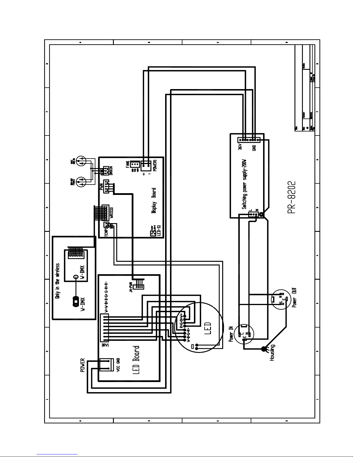
9. CIRCUIT DIAGRAM AND PCB CONNECTIONS
●
CIRCUIT DIAGRAM
Page 16
14
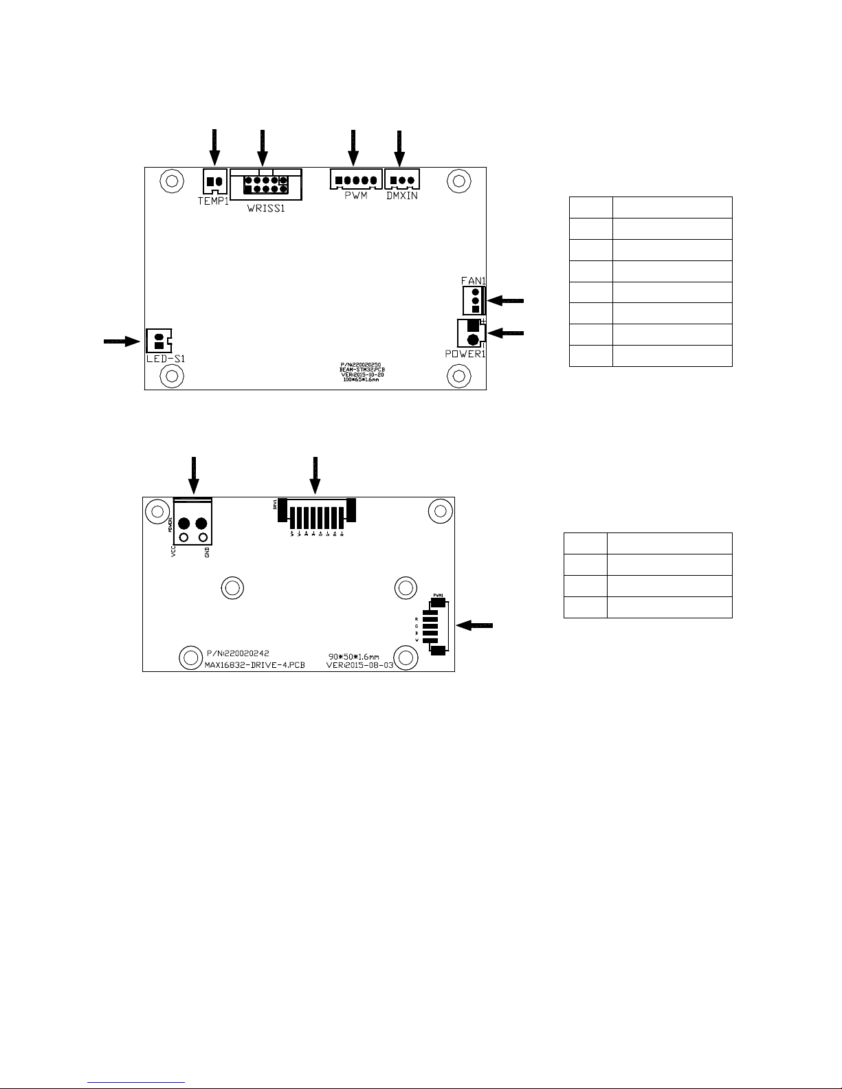
●PCB CONNECTIONS
Master Board (P/N230060494——Version with wireless function,P/N230060496——Version without wireless function)
Slaves (P/N230060486)
7
6
5
4
2
1
3
89
10
No. Name
1 Optical sensor
2 power supply
3 Fan
4 signal input
5 PWM signal
6 Wireless board
7 thermal switch
No. Name
8 LED driver
9 power supply
10 PWM signal input
Page 17

15
10. COMPONENT ORDER CODES
No. Name Code No. Qty Remarks
1
Power Switch 192010201 1
2
LED light source 150020300 1
3
LED Driver Board 230060486 1
4
LCD master board
230060494 1 Only for version with wireless control
230060496 1 Only for version without wireless control
5
Reflector 060060071 1
6
Front Glass Panel 080090114 1
7
Transparent Display Cover 290190109 1 Optional
8
Seal for Transparent Display Cover 290019142 1 Optional
9
Wireless Antenna W006506
1
Only for version with wireless control
10
Wireless Receiver W006511
1
Only for version with wireless control
Page 18

Page 19

PR LIGHTING LTD.
1582 Xingye Avenue, Nancun Panyu
Guangzhou, 511442 China
TEL: +86-20-3995 2888
PR lighting will try its best to offer accurate and overall information about a product’s technical data. Any changes won’t be notified if necessary. Patented Products.
Counterfeiting Will be Prosecuted!
P/N: 320020369
Version: 20151201
 Loading...