

Page 1
XLED 336 BEAM
PR-8110
This product manual contains important information about the safe installation and use of this
product. Please read and follow these instructions carefully before installing and using the product
and keep this manual in a safe place for future reference.
PR LIGHTING LTD.
http://www.pr-lighting.com
Page 2
2/16
INDEX
SAFETY INFORMATION AND WARNINGS 3
PRODUCT INSTALLATION 4
POWER SUPPLY CONNECTION 5
DMX CONTROL CONNECTION 5
DMX TERMINATOR 6
PRODUCT FUNCTION SETUP 6
DMX START ADDRESS SETUP 6
STAND-ALONE MODE 7
MASTER/SLAVE MODE 7
OPERATION MENU 8
DMX PROTOCOL 9
DISPLAY INFORMATION 10
MAINTENANCE 10
PRODUCT CLEANING 11
TROUBLESHOOTING 11
TECHNICAL DATA 11
COMPONENT ORDER CODES 14
CIRCUIT DIAGRAM 15
Every ex-company fixture is tested completely and packed properly by the manufacturer. The use explanations and warnings in this
manual must be strictly followed .Any damage caused by improper use will not be covered by the manufacturer and / or dealer.
If any technical data changes, further notice won’t be offered.
ACCESSORIES
These items are packed together with the product, please check them:
Name Quantity Unit Remark
XLR signal cable 1 PCS With plug and socket
Safety cord 1 PCS
This manual 1 PCS
G clamp 1 PCS Standard
Ω clamp 1 PCS Optional
FROST BOARD 1 PCS
Page 3

3/16
SAFETY INFORMATION AND WARNINGS
After receiving product, please unpack and check if there are any damages caused by transportation. Do not use the
fixture if transportation damages occur and contact the manufacturer or the dealer as soon as possible.
The product is only for indoor use, IP20. Use only in dry locations. Keep this device away from rain and moisture,
excessive heat, humidity and dust. Do not allow its contact with water or any other liquids .
The unit is only intended for installation, operation and maintenance by qualified personnel.
The product must be installed in a location with good ventilation, at least 50cm from adjacent wall surfaces. Be sure that
no fans and ventilation slots are blocked.
Do not project the beam onto inflammable surfaces, minimum distance is 1.3m.
1.3m
Avoid looking into the light from the fixture directly (especially to
Epileptic Patients). The light is harmful to the eye.
Do not attempt to dismantle and/or modify the product in any way.
Electrical connection must only be carried out by qualified personnel.
Before installation, ensure that the voltage and frequency of power supply match the power requirements of the fixture .
It is essential that each fixture is correctly earthed and that electrical installation conforms to all relevant standards.
Do not connect this device to any other types of dimmer apparatus.
Make sure that the power-cord is never crimped or damaged by sharp edges. Never let the power-cord come into contact
with other cables. If the fixture is not in use or before it being cleaned, please hold the plug and unplug the power cord .
Never pull out the plug by tugging the power-cord.
The fixture should always be installed with a secondary safety fixing. A safety cord is supplied for this; it should be
attached as shown in “installing the unit” section. At the back cover of the base, there is a safety hole for the safety cord,
for safety installation, please run the safety cord supplied with the fixture through the safety hole to support the safe
installation.
Shields and lens shall be changed if they have become visibly damaged to such an extent than their effectiveness is
impaired, for example by cracks or deep scratches.
Exterior surface temperatures of the luminaire after 5 minutes operation is 45℃, when steady, it achieves 50℃,
There is no user repairable parts inside the fixture, do not open the housing and never operate the unit with the covers
removed. Before the use of the fixture, please check if the covers are fixed well and all screws are fastened.
If any questions, don’t hesitate to consult your dealer or the manufacturer.
Important: Always disconnect from Power Supply, when the device is not in use or before
cleaning or any maintenance work!
Page 4
4/16
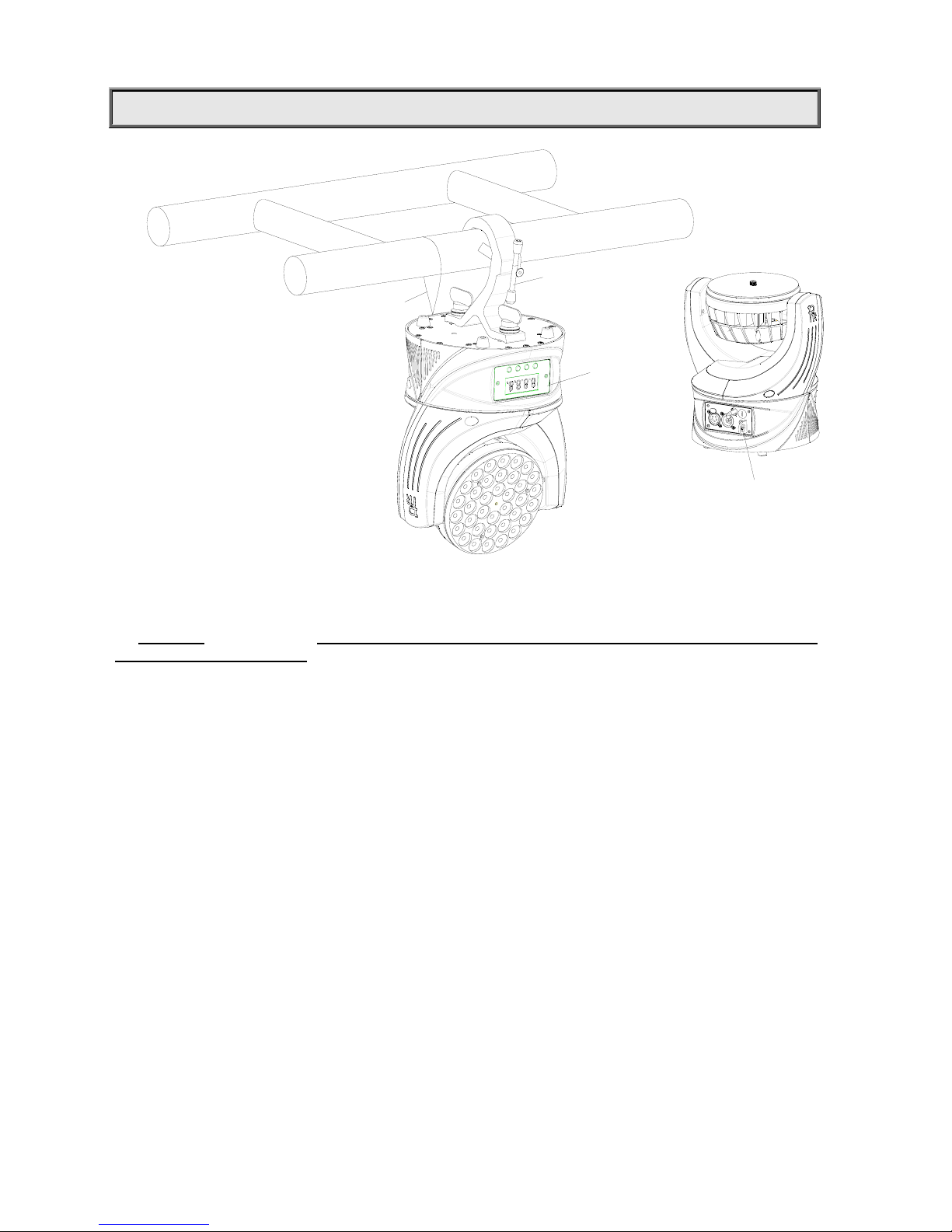
PRODUCT INSTALLATION
WARNING:
Please run the safety cord
through safety hole and
make sure that the cord is
property secured.
SAFETY
CORD
CLAMP
CONTROL
PANEL
Take 1 clamp and 1 the safety cord out from the package and mount 1 clamp on the BOTTOM of fixture with 2 retainers
attached to the clamp. Hang the fixture on the steel truss and fasten the retainers attached to the clamp. Always ensure
that the location that you are going to mount the unit is secure and is strong enough to support the weight of the unit (See
the WARNING
as shown above) To pass SAFETY CORD through the SAFETY HOLE on the back cover of the
base of the fixture for safety! Always ensure that the unit is firmly anchored to avoid vibration and slipping whilst
functioning.
WARNING:
1. The unit MUST be lifted or carried by the HANDLES instead of clamps.
2. For safety the safety cord should bear 10 times of the unit’s weight .
Page 5
5/16
POWER SUPPLY CONNECTIONS
Connect the power cord as follows:
L (live) =brown
E (earth) =yellow/green
N (neutral) =blue
Please be advised to notice power supply’s voltage and frequency meet what are described on the nameplate of the
product. It is recommended that each unit be power connected separately so that they may be individually switched on
and off.
IMPORT ANT
It is essential that each unit(yellow/green twin wire) is correctly earthed and the electrical installation conforms
to all relevant standards.
DMX CONTROL CONNECTION
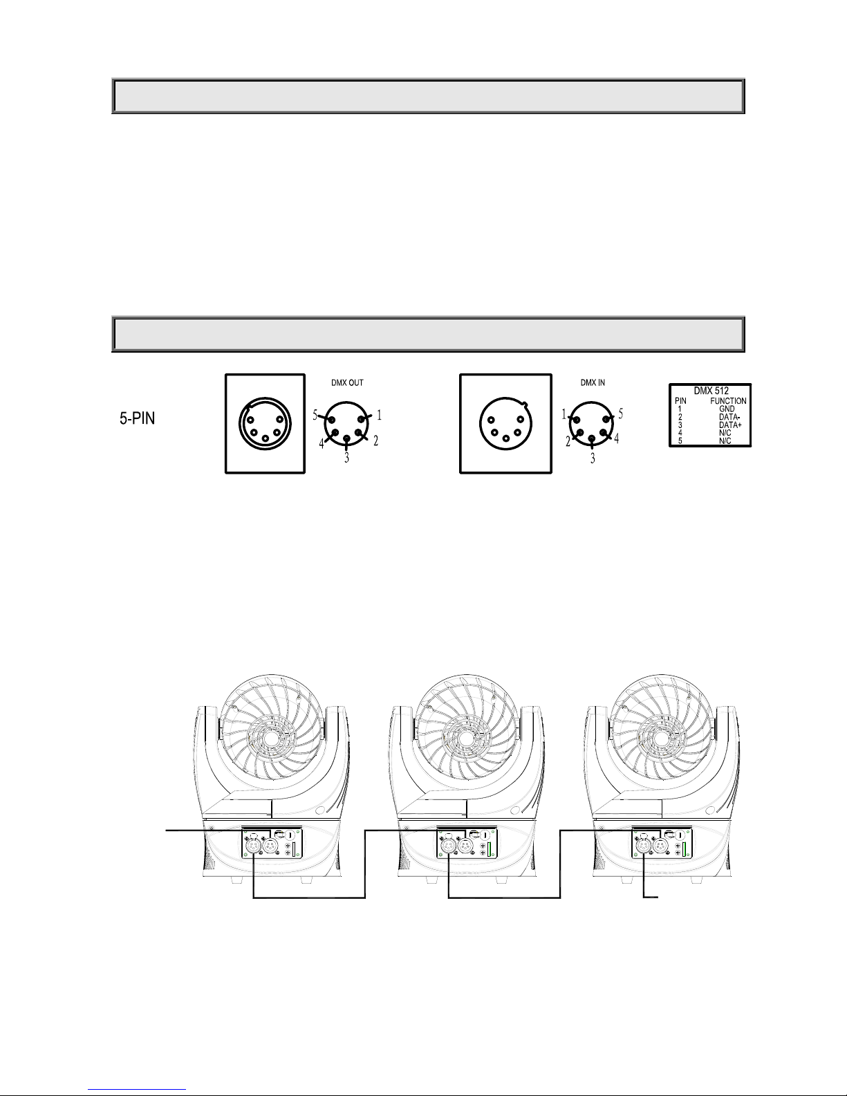
Connection between controller and unit and between one unit and another must be made with a 2 core-screened cable,
with each core having at least a 0.5mm diameter. Connection to the DMX512 input and output ports of the unit is via 5
pin XLR plugs and sockets(which are included with the unit). The XLR's plugs and sockets are connected with wires as
shown in the figure above. Note: care should be taken to ensure that none of the pins touch the metallic body of the plug
or each other. XLR’s plug and socket must not be connected with XLR control wire in any way other than shown as
above. The fixture accepts digital control signals in protocol DMX512 (1990).
Connect the controller’s output to the first fixture’s input, and connect the first fixture’s output to the second fixture’s input
and connect the rest fixtures in the same way. Eventually connect the last fixture’s output to a DMX terminator as shown
in the figure below.
MASTER
DMX IN FROM
CONTROLLER
DMX OUT
DMX IN
TERMINATOR
SLAVE SLAVE
DMX OUT
DMX IN
Page 6
6/16
DMX TERMINATOR
In the Controller mode, at the last fixture in the chain, the DMX output has to be connected with a DMX terminator. This
prevents electrical noise from disturbing and corrupting the DMX512 control signals.
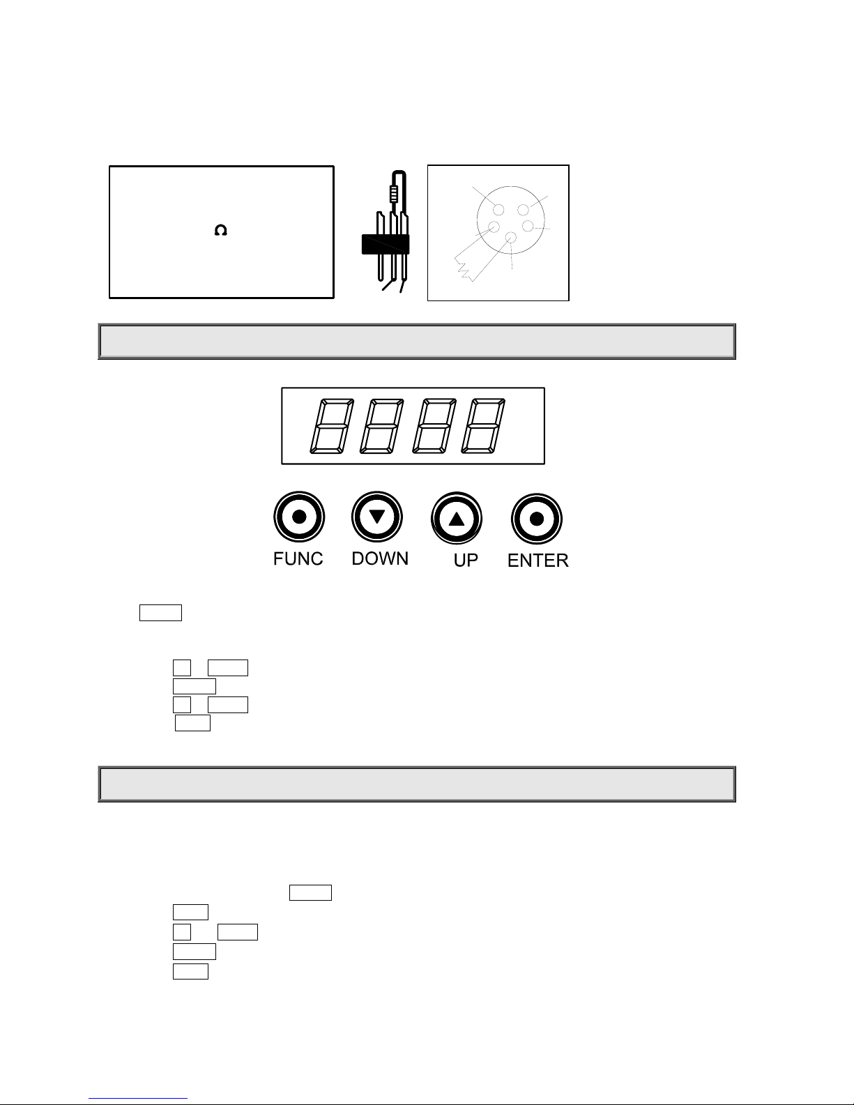
The DMX terminator is simply a Canon connector with a 120Ω (ohm) resistor connected across pins 2 and 3, which is
then plugged into the output socket on the last fixture in the chain. The connections are illustrated below.
DMX TERMINATOR
CONNECTION
Connect a 120 (OHM) resistor
across pins 2 and 3 in an XLR plug
and insert into the DMX out socket
on the last unit in the chain.
PIN 3
PIN 2
PRODUCT FUNCTION SETUP
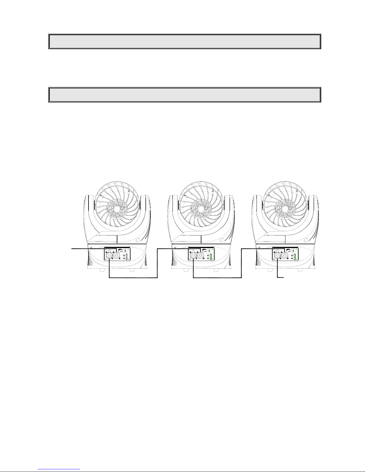
Fixture’s address and function code configuration can be set conveniently via button switch and LCD display. Press
button ENTER more than 5 seconds to unlock panel. LED display shows the fixture’s function menu. Each Option of the
main menu has its own sub-menu. Each menu stands for specified function of the fixture, please see the details in the
following:
Press button UP or DOWN if you want to set or browse through the various Setup Options.
Press button ENTER to save your settings or enter the sub-menus.
Press button UP or DOWN to change the parameters(increase or decrease the numbers)
Press button FUNC, it will return to the upper menu one by one. If the button not pressed, the system will go back to
display status automatically.
TO SET THE DMX START ADDRESS
If many fixtures are controlled by the controller, each fixture should be set with a start address to receive signals sent by
the controller and respond to it. The fixture have 2 DMX modes. There are standard mode and extended mode For
example standard mode has 12 channels, so set the No. 1 Fixture’s address 001, No. 2 Fixture’s address 013, No. 3
Fixture’s address 025 and so on.
Switch on the Fixture. Press button ENTER more than 5 seconds to unlock panel.
Press button FUNC to display DMX address;
Press button UP and DOWN, you can set the address;
Press button ENTER to confirm; when powered on next time, it will show the latest number you saved.
Press button FUNC, it will return to the upper menu one by one.
1
2
3
4
5
120
Page 7
7/16
STAND-ALONE MODE
Operate the fixture without connecting a controller, enable the master mode in the operation panel, the fixture will run in
Stand-Alone mode automatically.
MASTER/SLAVE MODE
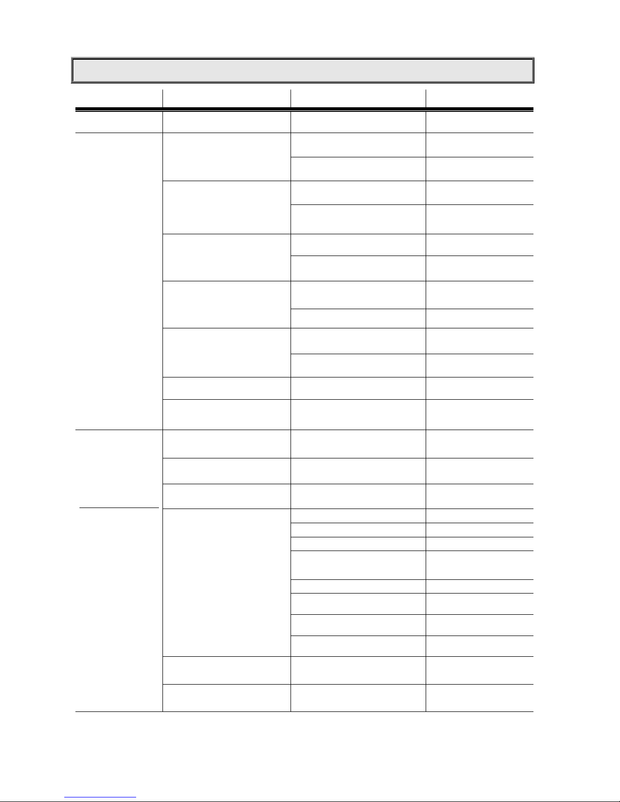
If many fixtures are connected under Master/Slave mode, use XLR-XLR control cable to connect the first fixture’s DMX
output port with the second fixture’s DMX input port, then to connect the second fixture’s output port with the third fixture’s
input port and so on until all the fixtures are connected, the last thing is to plug the terminator at the last fixture’s output
port. In this case, the first fixture is the master, others are slaves
Set the master’s address at 001, Master can be set at any mode(STD mode or extended mode) and slave should be set
at same mode as the master’s.
After powered on, the group will run under Master/Slave mode.
MASTER
DMX IN FROM
CONTROLLER
DMX OUT
DMX IN
TERMINATOR
SLAVE SLAVE
DMX OUT
DMX IN
Page 8
8/16
OPERATION MENU
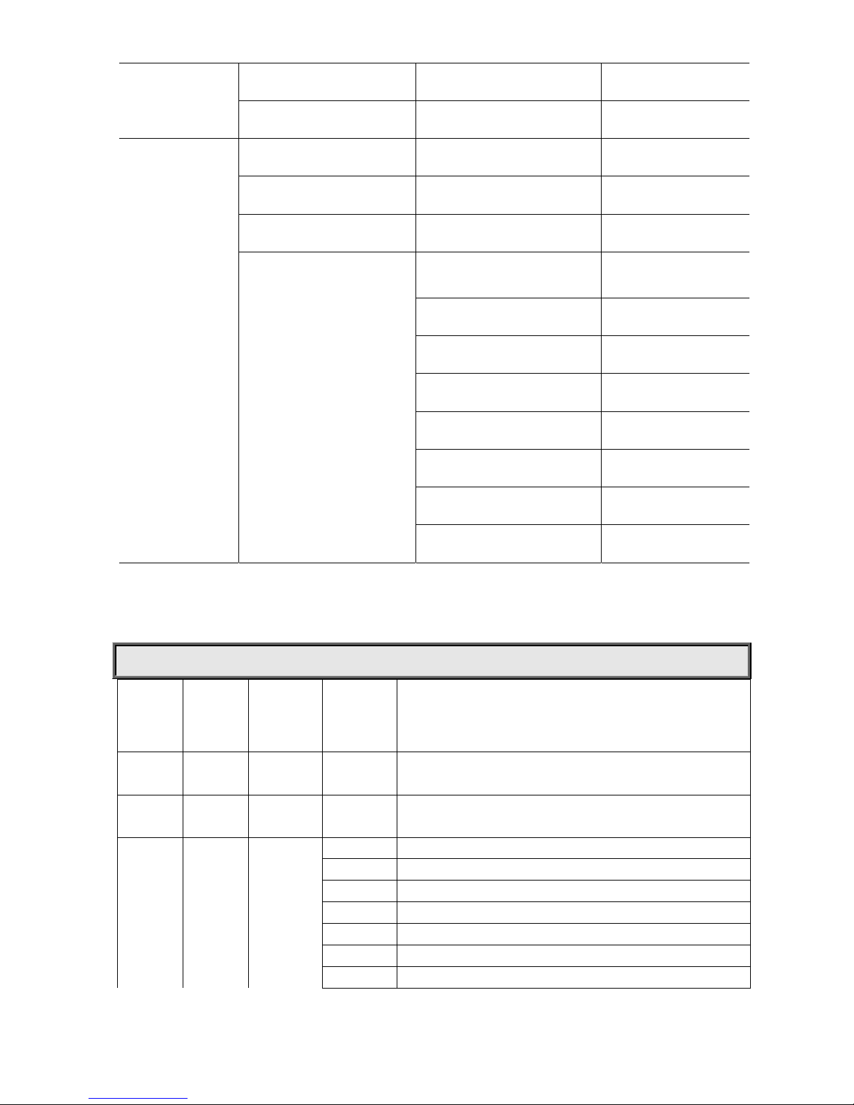
1st LEVEL 2nd LEVEL 3rd LEVEL 4th LEVEL
AddR
DMX Address
XX
X
(XXX:1~512)
CNFG
Config Settings
dmX
DMX mode
(Default is:STd)
STd
Standard mode
EXT
Extended mode
dISP
Display settings
(Default is:ON)
ON
OF
F
digital CRT off if buttons not
p
ressed in 5 minutes
xyCH
Pan Tilt Swap(Default is OFF)
OFF
Pan Tilt Swap off
ON
Pan Tilt Swap on
xyCP
Pan Tilt Invert(Default is OFF)
OFF
Pan Tilt Invert off
O
N
Pan Tilt Inver
t
on
mORS
Master/Slave Settings
(Default is slave)
SLAV
Slave Mode
mAST
Master Mode
FACT
Factory Defaults
yES
TRmd(1)
Transmit parameters
yES
INFO
(Information)
TEST
(test mode)
TImE
(Fixture usage time)
XXXX
Fixture usage time showed
VER
(Software version)
X.X.X
Software Version No.
TEmP
TEMP
X.X.
LED lamp PCB temp showed
Lamp
LED Lamp l
OFF(shut off)
R (red)
G (Green)
B (Blue)
RG (Yellow)
GB (cyan)
RB (purple)
RGB(White)
Pan
0-255 540°
TILT
0-255 270°
Page 9
9/16
P*TS
Pan/Tilt speed
0-255 Pan/Tilt speed
RESE
Reset
YES
mENU
Operation Mode
dmx
DMX mode
PRUN
Run preset memory
ERUN
Run user program
ET XX
User memory from
(ET 01 to ET16)
CH01
Strobe
0-255
CH02
Red Dimming
0-255
CH03
Greening Dimming
0-255
CH04
Blue Dimming
0-255
CH05
Pan
0-255
CH06
Tilt
0-255
CH07
Pan/Tilt Speed
0-255
CH15
Scene hold time
0-255
Time=X*40mS
Remark:
1. In the synchronous control of multiple fixtures, parameters can be transmitted from the master includes: DMX
mode, display setting, operation mode(Including user memory);
DMX Protocol
Standard
Mode
Extended
Mode
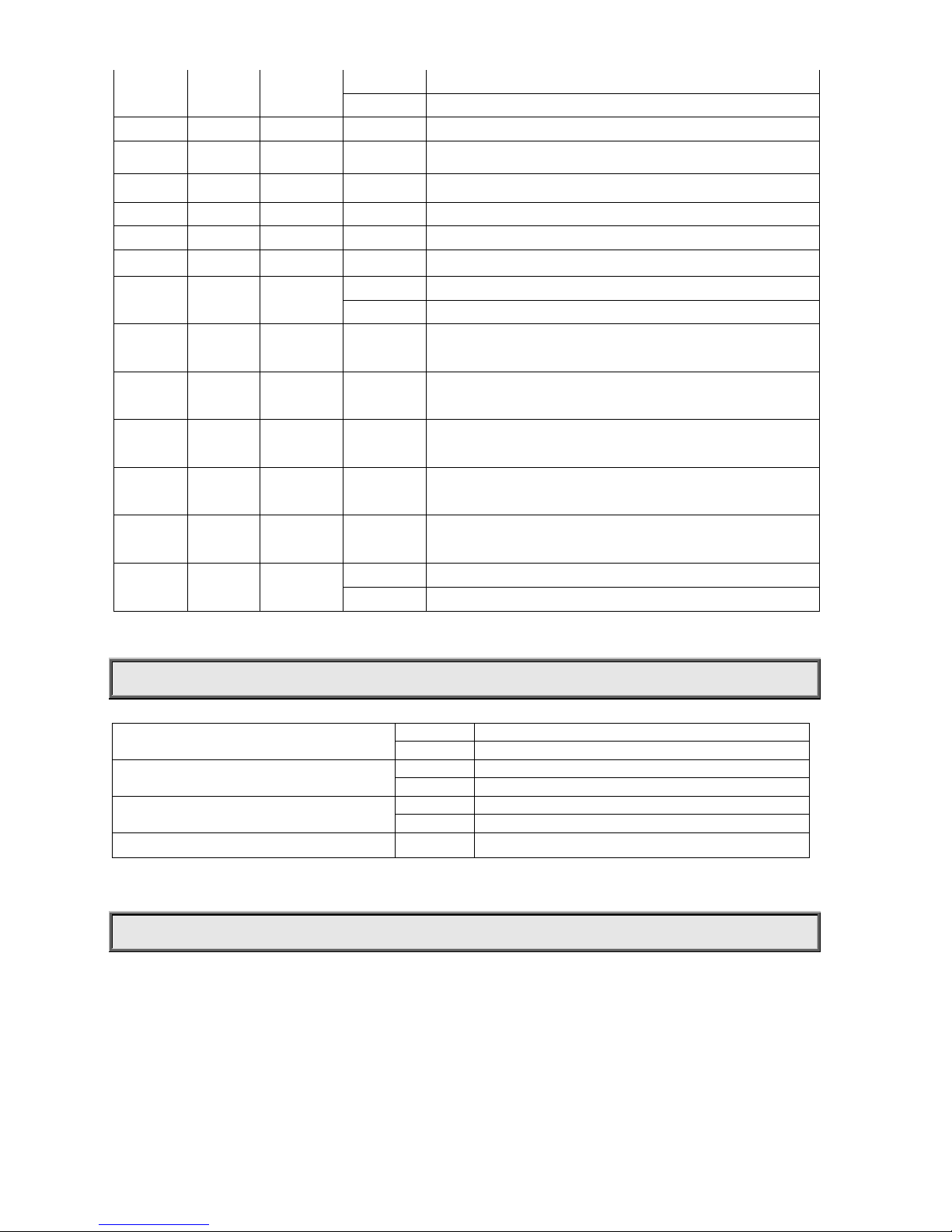
Function DMX Value Description
1 1 Dimmer 000-255 Linear dimming from dark to bright
2
Dimmer
16 Bit
000-255 Linear dimming from dark to bright
2 3
Macro
0 Nil
001-031 Red
032-063 Green
064-095 Blue
096-127 Yellow
128-159 Cyan
160-191 Purple
Page 10
10/16
192-223 White
224-255 Red & White
3 4 Red 000-255 Linear dimming from dark to bright
4 5 Green 000-255 Linear dimming from dark to bright
5 6 Blue 000-255 Linear dimming from dark to bright
7 Hue 000-255 Hue Options
8 Saturation 000-255 Saturation from light to dark
9 Brightness 000-255 From Dark to Bright
6 10 Strobe
0 Nil
001-255 Strobe speed from slow to fast
7 11
Pan
000-255
Pan 540°
8 12
Pan 16 Bit
000-255 Pan 16 bit Precision Rotation
9 13
Tilt
000-255
Tilt 270°
10 14 Tilt 16 Bit 000-255
Tilt 16 Bit precision rotation
11 15
Pan/Tilt
Speed
000-255 From fast to slow
12 16 Control
000-048 Reserved
049-255 Reset
. INDICATION OF LED DIGITAL TUBE
Decimal point of the first digital tube
On DMX signal OK
Off No DMX signal
Decimal point of the third digital tube
On Master / slave signal is OK
Off No master / slave signal
Decimal point of the fourth digital tube
On When setting master mode
Off When setting slave mode
Parameters that LED digital tubes display Flash Parameters not saved, press “ENTER” to save them
MAINTENANCE
If the Fixture does not function, check if the fuses on the power socket of the unit is broken or not, if broken, they should
only be replaced by fuses of the same specification. Should there be damaged call a qualified technician before
replacement. The fixture has thermal protection device that will switch off the unit in case of overheating. Should any
case like this happen, check if the fans work well or fans and fan screens are blocked, restart the fixture before the
problems have been found and resolved.
Any maintenance work sh ould only be carried out by qualified tec hnicians.
Page 11
11/16
PRODUCT CLEANING
To ensure the reliability of the fixture it should be kept clean. It is recommended that the fans should be cleaned every 15
days. The lens should also be regularly cleaned to maintain an optimum light output.
Do NOT use any type of solvent
containing chemi cal element s.
Cleaning intervals depends on the environment in which the fixture operates and use frequency. A soft cloth and typical
glass cleaning products should be used in cleaning the fixtures. It is recommended to clean the external optical system at
least once every 20 days.
Do not use any organic solvent, e.g. alco hol, to clean the housing o f the appara tus to avoid damages
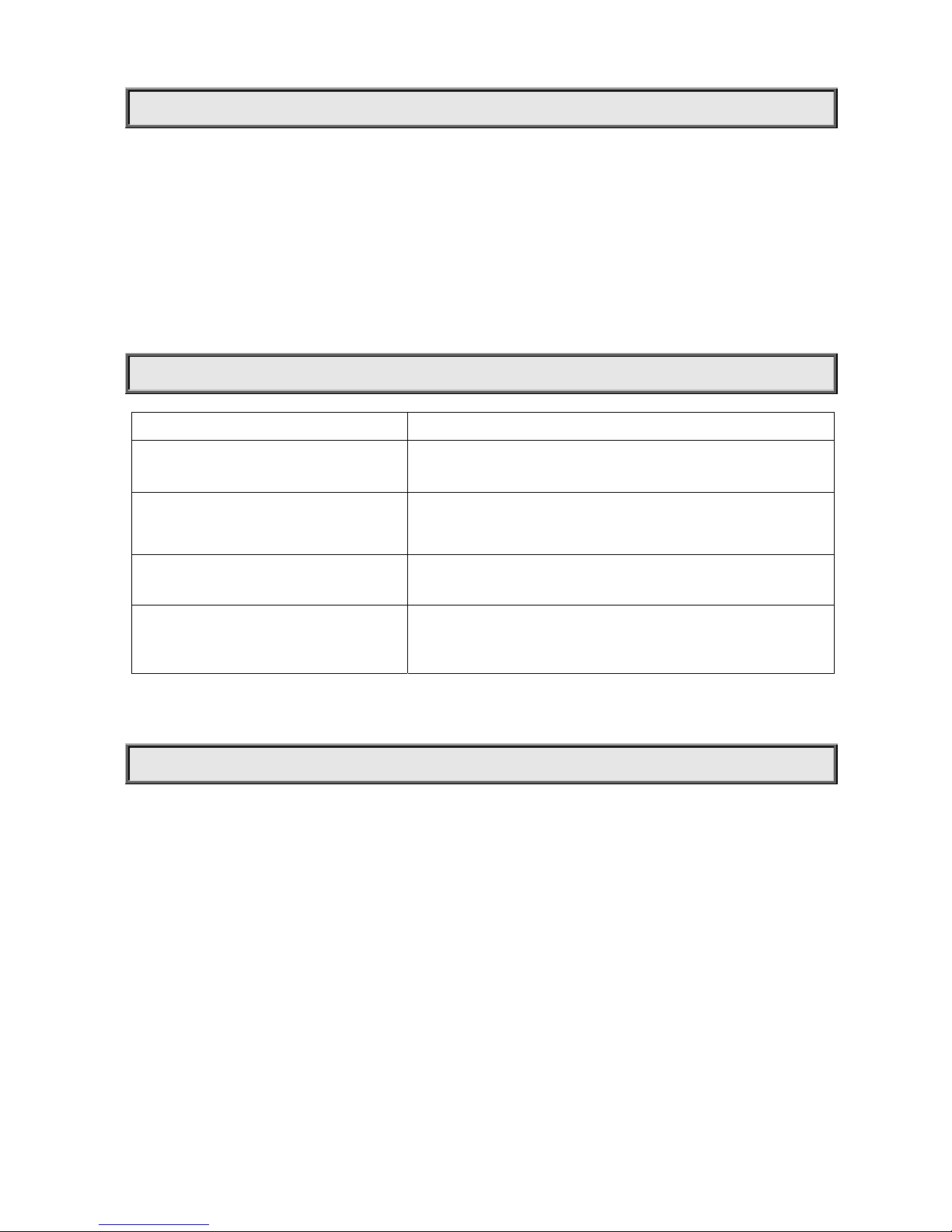
TROUBLE SHOOTING
PROBLEM ACTION
The fixture can not start
¾ Check if the fuse on the power socket is broken or not .
¾ Check the status of the fuse
The lamp works normal but the fixture
doesn’t respond to the controller
¾ Check if the fixture’s start address is set properly
¾ Check if XLR signal cable is broken or not
The fixture only functions intermittently
¾ Make sure the fans work normally and if dirt blocks fans and fan
screens.
The beam appears dim and brightness
decreases apparently
¾ Check if the lamps reach the end of their lives
¾ Check if external and internal optical systems are clean or not.
TECHNICAL DATA
LIGHT SOURCE:
OSRAM OSLON 3W(12R+12G+12B)
VOLTAGES:
90~264VAC 50/60HZ
POWER CONSUMPTION:
140W@220V
COLOR SYSTEM:
RGB color mixing system
2700K~10000K
Page 12

12/16
DIMMER:
0-100% linearly adjustable
STROBE:
Electronic strobe, 0.3~20 F.P.S
HEAD MOVEMENT :
Pan 540º, Tilt 270º;
Pan Tilt Swap and Invert Function ;Auto-position correction & Magnetic sensor positioning.
LENS ANGLE: 8°
FIELD ANGLE (Wi thout Frost board) : (One-tenth-peak luminance angle) 17°
BEAM ANGLE (Without Frost board) : (Half-peak luminance angle) 8°
FIELD ANGLE (With Frost board) : (One-tenth-peak luminance angle) 32°
BEAM ANGLE (With Fr ost board) : (Half-peak luminance angle) 16°
CONTROL:
DMX512, 5 pin interfaces
12channels in standard mode, and 16channels in extended mode.
Master/slave mode
Stand-alone mode
Built-in mode
OTHER FUNCTIONS:
Adjustable Pan & Tilt speed
Fixture usage time display
Software version display
Modular structure for easy maintenance
HOUSING:
High temperature engineering-plastic, IP20
WEIGHT:
4.2Kg
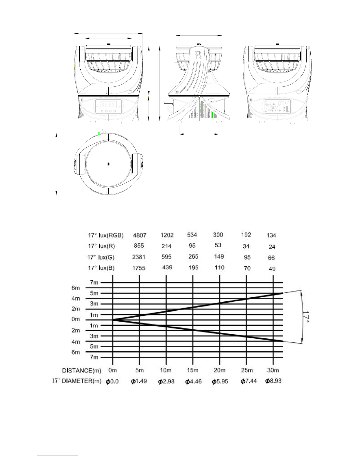
SIZES:
See at below
Page 13
13/16
223.88
81
160.76
244.36
153
149.99
204
130
LIGHT OUTPUT (WITHOUT FROST BOARD):
Page 14
14/16
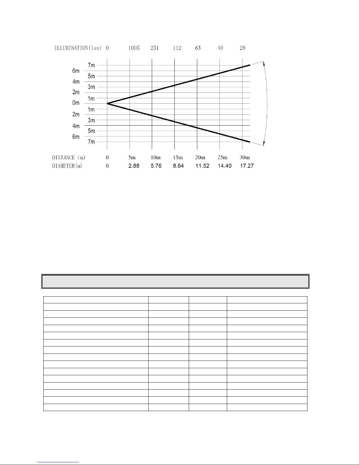
LIGHT OUTPUT (WITH FROST BOARD):
COMPONENT ORDER CODES
NAME PART NO. QUANTITY REMARK
POWER SUPPLY 192010150 1 PCS 90-264V AC/3.0 A
LED ( RED COLOR) 150020217 12 PCS 3Wx12
LED ( BLUE COLOR) 150020218 12 PCS 3Wx12
LED (GREEN COLOR) 150020219 12 PCS 3Wx12
LENS 070070011 1 PCS
FUSE 270041037 1 PCS 5x20 3.15A
TILT/PAN BELT 290151337 2 PCS HTD-3M-297
FAN 030060077 1 PCS 24V,ME70202V3
FAN 030060076 1 PCS 24V, AD0424LB
PAN/TILT MOTOR 030040175 2PCS
LED DRIVER PCB 230060106 1 PCS
LED PCB 230060107 1 PCS
PAN AND TILT PCB 230060155 1 PCS
DISPLAY PCB 230060117 1 PCS
FROST BOARD 120110365 1 PCS
320
Page 15
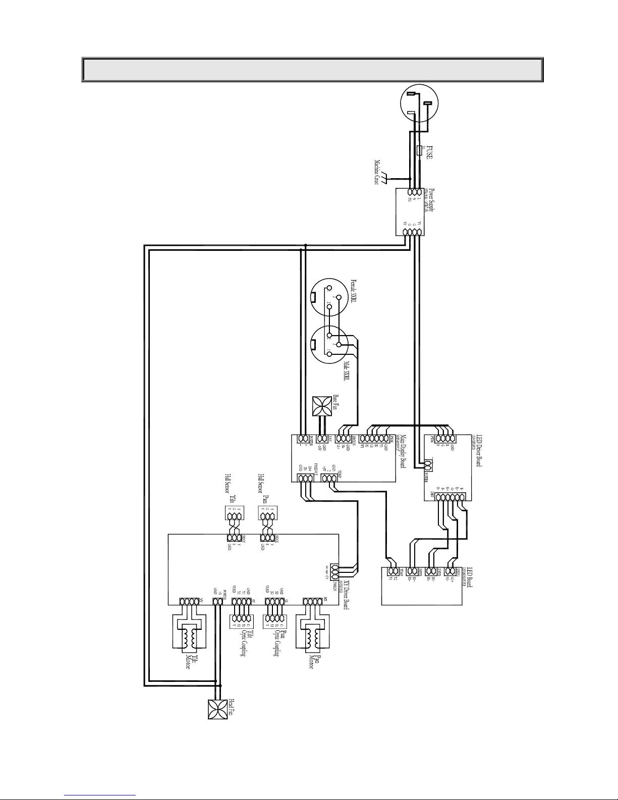
15/16
CIRCUIT DIAGRAM
Page 16

16/16
PR LIGHTING LTD.
1582 Xingye Avenue, Nancun Panyu
Guangzhou, 511442 China
TEL: +86-20-3995 2888
FAX: +86-20-3995 2330
P/N: 320020115
Version: 20121126
 Loading...