

Page 1

PILOT 1200
PR-2900
This product manual contains important information about the safe installation and
use of this projector. Please read and follow these instructions carefully and keep this
manual in a safe place for future reference.
PR LIGHTING LTD.
No. 571, Yingbin Road, Dashi Panyu, Guangzhou, 511430 China
http://www.pr-lighting.com
Page 2

SAFE USAGE OF THE PROJECTOR 3
INDEX
INSTALLING THE PROJECTOR 4
FITTING THE LAMP 4
POWER SUPPLY – MAINS 5
CONTROL CONNECTIONS 5
DMX TERMINATOR 6
SETUP OPTIONS-PROJECTOR CONFIGURATION 6
TO SET THE DMX START ADDRESS 6
FUNCTIONS DISPLAY 7
ERRORS DISPLAY 9
REPLACING GOBOS 9
DMX CONTROL CHANNEL FUNCTIONS 10
LED DISPLAY 12
CHANGING BELTS 12
MAINTENANCE 13
LUBRICATION 13
KEEPING THE PROJECTOR CLEAN 13
TROUBLESHOOTING 13
TECHNICAL DATA 15
ELECTRICAL DIAGRAM 17
COMPONENT ORDER CODES 18
CHANGING THE OPERATION FREQUENCY 19
Please note that as part of our ongoing commitment to continuous product development, specifications are
subject to change without notice. Whilst every care is taken in the preparation of this manual we reserve the
right to change specifications in the course of product improvement. The publishers cannot be held responsible
for the accuracy of the information herein, or any consequence arising from them.
Every unit is tested completely and packed properly by the manufacturer. Please make sure the packing and / or
the unit are in good condition before installation and use. Should there be any damage caused by transportation,
consult your dealer and do not use the unit. Any damage caused by improper use will not be assumed by the
manufacturer and / or dealer.
ACCESSORIES
THESE ITEMS ARE PACKED TOGETHER WITH THE PROJECTOR
G clamps (2 PCS)
XLR cable with 3-pin plug and socket (1 PCS)
Safety cord (2 PCS)
Spare gobos (4 PCS)
T his manual (1 PCS)
Ω clamps(Options)(2PCS)
Thank you for purchasing our product PILOT 1200, PR-2900.
INTRODUCTION
This product manual contains important information about the safe installation and use of this projector.
Please read and follow these instructions carefully and keep this manual in a safe place for future
reference.
PILOT 1200 is an innovative projector with an elegant housing, which complies to CE norms and
standards and uses international protocol DMX 512.
The projector uses HMI1200W/S discharge lamp and high quality optical system, which produces
bright and beautiful light beam and has 60% output lumen more than the similar products with the
same power consumption. The projector features effects of strobe, frost light, mixed colours and
rainbow, so it is suitable for applications in TV station, disc, singing and dancing stage, nightclub, etc.
Pilot 1200 manual.doc
2/20
Page 3

SAFE USAGE OF THE PROJECTOR
When unpacking and before disposing of the carton check there is no transportation damage before
using the projector. Should there be any damage caused by transportation, consult your dealer and do
not use the apparatus.
The projector is for indoor use only, IP20. Use only in dry locations. Keep this device away from rain
and moisture, excessive heat, humidity and dust. Do not allow contact with water or any other liquids.
The projector is not designed or intended to be mounted directly on to inflammable surfaces.
The projector is only intended for installation, operation and maintenance by qualified personnel.
The projector must be installed in a location with adequate ventilation, at least 50cm from adjacent
wall surfaces. Be sure that no ventilation slots are blocked.
Do not project the beam onto inflammable surfaces, minimum distance is 5m.
5m
Avoid direct exposure to the light from the lamp. The light is harmful to the eye.
Do not attempt to dismantle and/or modify the projector in any way.
Electrical connection must only be carried out by qualified personnel.
Before installation, ensure that the voltage and frequency of power supply match the power
requirements of the projector.
It is essential that each projector is correctly earthed and that electrical installation conforms to all
relevant standards.
Do not connect this device to any other types of dimmer apparatus.
Make sure that the power-cord is never crimped or damaged by sharp edges. Never let the powercord come into contact with other cables. Only handle the power-cord by the plug. Never pull out the
plug by tugging the power-cord.
Keep the lamp clean. Do not touch the lamp glass with bare hand.
The projector should always be installed with a secondary safety fixing. A safety cord is supplied for
this; it should be attached as shown in “installing the projector” section.
The lamp used in this projector is an HMI1200W/S discharge lamp. After switching off don’t attempt to
restart the projector until lamp has cooled, this will require approx 15 minutes. Switching the lamp on
and off at short intervals will reduce the life of both the lamp and the projector. But occasional breaks
will prolong the life of the lamp and projector.
Never run the projector without a lamp.
There is no user serviceable parts inside the projector, do not open the housing and never operate the
projector with the covers removed.
Always disconnect from the mains, when the device is not in use or before cleaning it or before
attempting any maintenance work.
If you have any questions, don’t hesitate to consult your dealer or manufacturer.
Pilot 1200 manual.doc
3/20
Page 4
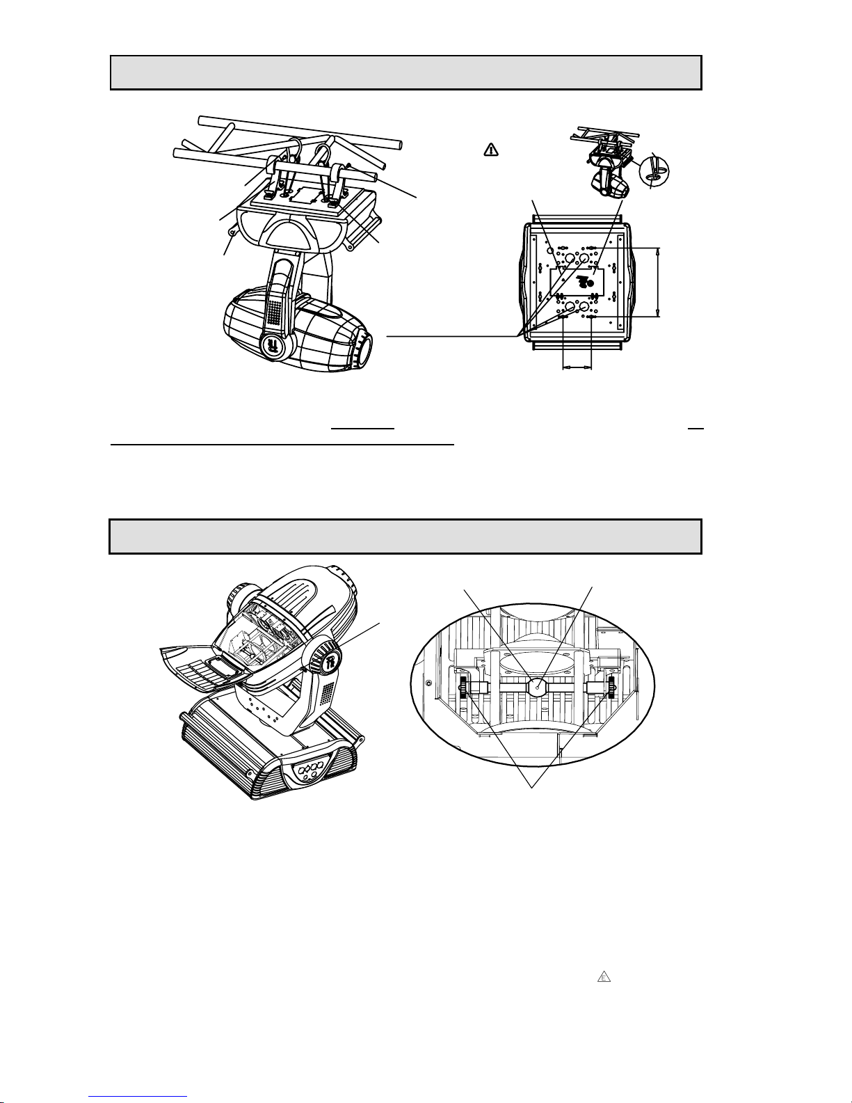
INSTALLING THE PROJECTOR
4 HOLES FOR
SAFETY CORD
PASSING THROUGH
CLAMPS
SAFETY CORD
(2PCS)
(1PCS PER CLAMP)
SCREWS
HANDLES
(2PCS)
(2PCS PER CLAMP)
RETAINERS
CORD
SAFETY
HOLE
WARNING
through 4 HOLES for safety!
To pass 2 SAFETY CORDS
WARNING
through 4 HOLES for safety!
To pass 2 SAFETY CORDS
CORD
SAFETY
HOLE
106
256
(2PCS)
Take 2 clamps and 2 safety cords out from the package and mount 2 clamps on the underside of
fixture with 2 retainers attached to each clamp. Hang the fixture on the structure and fasten the screws
attached to each clamp. (Watch the
WARNING on the underside of the base as shown above) To
pass 2 SAFETY CORDS through 4 HOLES for safety! Always ensure that the projector is firmly
anchored to avoid vibration and slipping whilst functioning. Always ensure that the structure that you
are going to mount the projector is secure and is strong enough to support a weight of PILOT 1200.
WARNING: 1. Unlock the PAN and TILT before the 1st application of projector for safety.
2. The projector MUST be lifted or carried by the HANDLES instead of clamps.
FITTING THE LAMP
TILT LOCK
NUTS
BULB
PST
Lock tilt before fitting/replacing the lamp.
Loosen 2 M5 screws and open one of the rear covers, you can see the structure as shown in the
figure above.
Loosen 2 nuts at the both ends of lamp and take out the worn-out lamp. Suggest to free one end after
another.
Fit new lamp and fasten 2 nuts at the both ends of lamp. Notes: don’t touch the bulb of the new lamp
with bare hand so as not to influence the beam output; the PST (pumping stem tip off) on the bulb
facing the rear cover with fans perpendicularly and being not in the beam’s way is a must and aids
cooling.
Close the rear cover and fasten 2 M5 screws.
WARNING: The HMI series are high-pressure lamps with external igniters (
). Care should
always be taken when handling these lamps. Always read the manufacturers "Instructions for
use" enclosed with the lamp.
Pilot 1200 manual.doc
4/20
Page 5
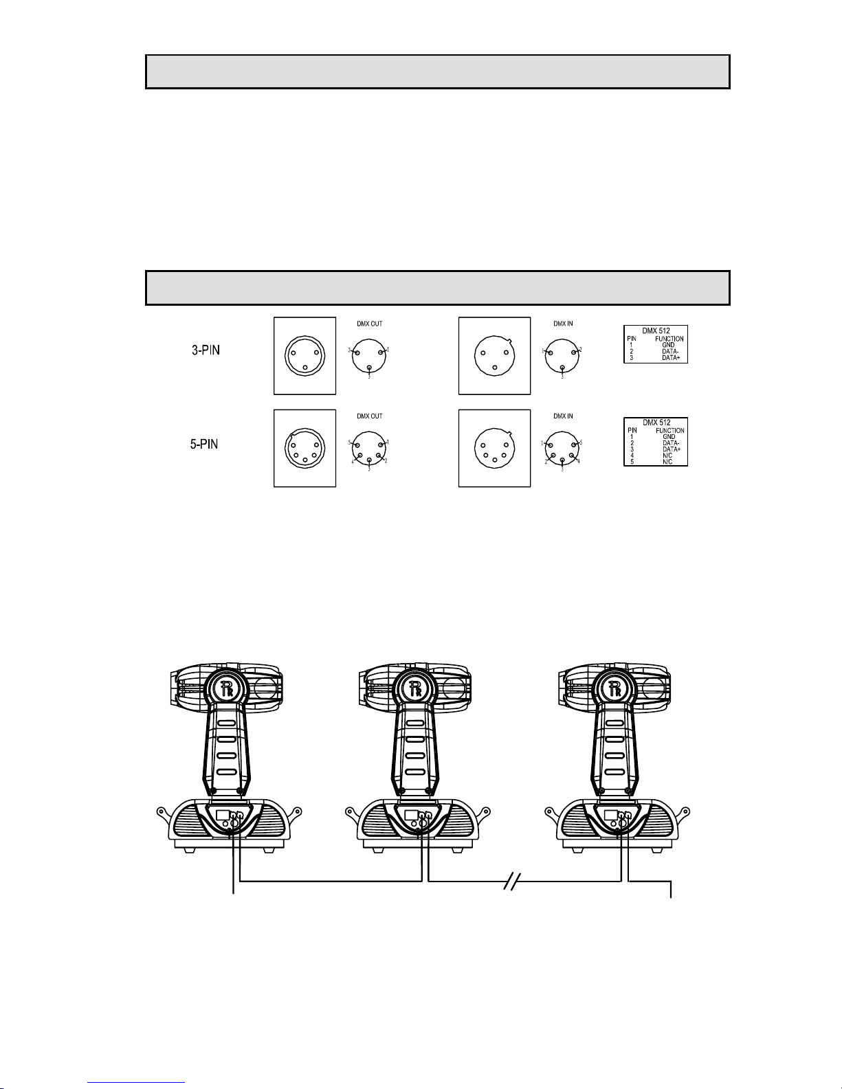
Connect the power cord as follows:
POWER SUPPLY - MAINS
L (live) =brown
E (earth) =yellow/green
N (neutral) =blue
Use the plug provided to connect the mains power to the projector paying attention to the voltage and
frequency marked on the panel of the projector. It is recommended that each projector be supplied
separately so that they may be individually switched on and off.
IMPORTANT
It is essential that each projector is correctly earthed and the electrical installation conforms to
all relevant standards. Power consumption of the PILOT 1200 is 1628W.
CONTROL CONNECTIONS
Connection between controller and projector and between one projector and another must be made
with a 2 core-screened cable, with each core having at least a 0.5mm diameter. Connection to and
from the projector is via cannon 3 pin (which are included with the projector) or 5 pin XLR plugs and
sockets. The XLR's are connected as shown in the figure above.
Note: care should be taken to ensure that none of the pins touch the metallic body of the plug or each
other. The body of the plug is not connected in any way. The PILOT 1200 accepts digital control
signals in protocol DMX512 (1990).
Connect the controller’s output to the first fixture’s input, and connect the first fixture’s output to the
second fixture’s input and connect the rest fixtures in the same way. Eventually connect the last
fixture’s output to a DMX terminator as shown in the figure below.
DMX OUTDMX INDMX OUTDMX IN
TERMINATOR
DMX IN FROM
CONTROLLER
DMX IN DMX OUT
Pilot 1200 manual.doc
5/20
Page 6
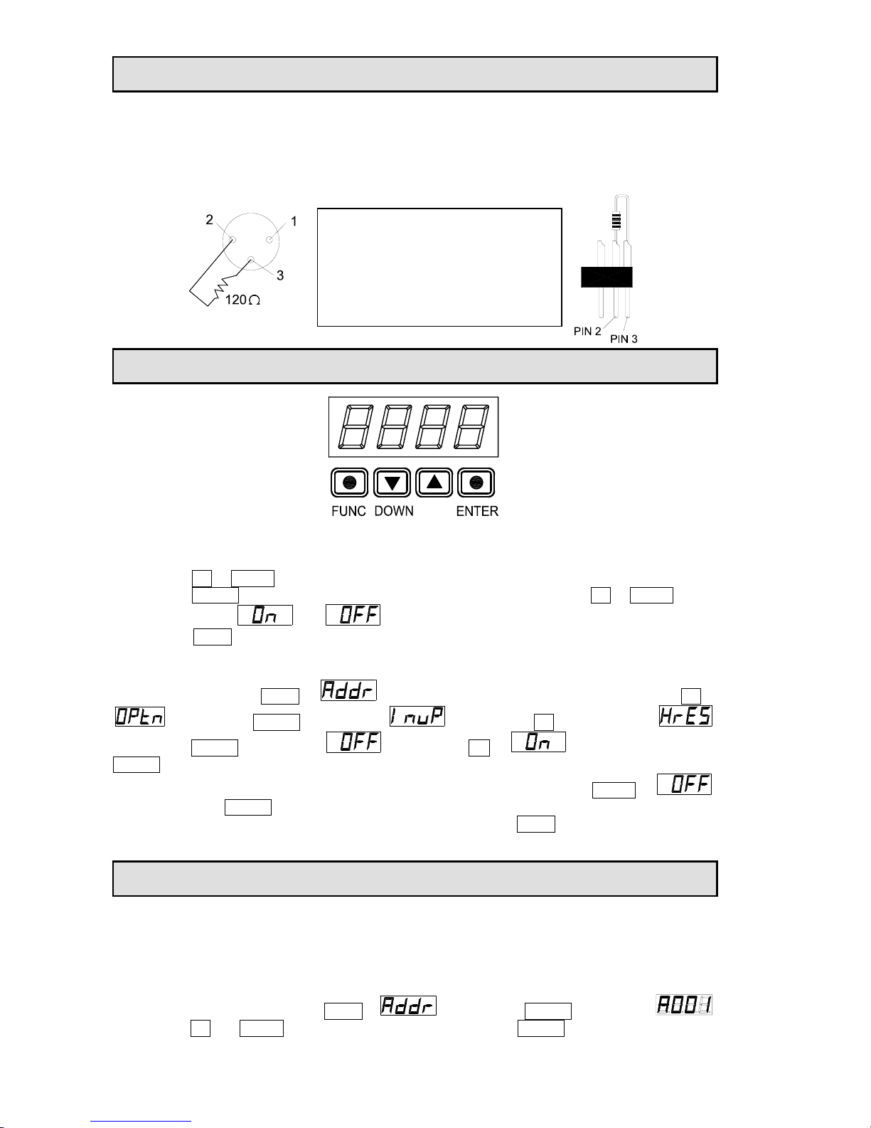
In the Controller mode, at the last fixture in the chain, the DMX output has to be connected with a DMX
terminator. This prevents electrical noise from disturbing and corrupting the DMX control signals.
The DMX terminator is simply an XLR connector with a 120Ω (ohm) resistor connected across pins 2
and 3, which is then plugged into the output socket on the last projector in the chain. The connections
are illustrated below.
DMX TERMINATOR CONNECTION
Connect a 120Ω(OHM) resistor across
pins 2 and 3 in an XLR plug and insert
into the DMX OUT socket on the last
unit in the chain.
DMX TERMINATOR
SETUP OPTIONS - PROJECTOR CONFIGURATION
UP
Projector configuration can be set conveniently via pressbutton switch and digital display. Turn the
projector on and the digital display will show DMX address you set and save last time and it can be
reset and saved again as you please.
Press button UP or DOWN if you want to browse through the various Setup Options.
Press button ENTER to save your settings or enter the next menu. Press button UP or DOWN to shift
the display between and or change the display of address.
Press button FUNC, it will return to the upper menu one by one. The display will return automatically
to the function of address display if you stay for about 60 seconds defaulted.
E.g. if you want to set the function of Pan、 Tilt 16bit precision valid, do as follows: launch the
apparatus; press button FUNC to
which is displayed in digital display; press button UP to
; press button ENTER, it will display ; press button UP consecutively to ;
press button ENTER, it will display ; press button ON to ; in the end, press button
ENTER. Well done, you have validated this function now.
If you want to set the function of Pan、Tilt 16bit precision invalid, press button DOWN to ;
Then press button ENTER to invalidate this function.
And, if you want to set another function valid or not, press button FUNC to track back one by one;
then, do the same way of e.g. above.
TO SET THE DMX START ADDRESS
Each PILOT 1200 must be given a DMX start address so that the correct projector responds to the
correct control signals. This DMX start address is the channel number from which the projector starts
to “listen” to the digital control information being sent out from the controller. The PILOT 1200 has 22
channels, so set the No. 1 projector’s address 001, No. 2 projector’s address 023, No. 3 projector’s
address 045, No. 4 projector’s address 067, and so on.
Launch the projector. Press button FUNC to
; press button ENTER, it will display ;
press button UP and DOWN, you can set the address; press button ENTER to confirm.
Pilot 1200 manual.doc
6/20
Page 7
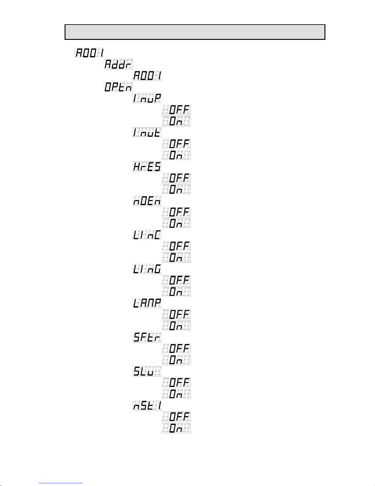
FUNCTIONS DISPLAY
(RESERVED)
(RESERVED)
(RESERVED)
LAMP SWITCH
(RESERVED)
ON
OFF
ON
OFF
OFF
ON
SLAVE IN MASTER/SLAVE MODE
OFF
ON
MASTER MODE 1
OFF
ON
OFF
ON
OFF
ON
OFF
ON
OFF
ON
FIXED GOBO WHEEL LINEAR SWITCH
COLOUR FILTER LINEAR SWITCH
CODER SWITCH(PHOTOCOUPLER POSITIONING)
PAN\TILT 16 BIT PRECISION SWITCH
TILT ANTI-CLOCKWISE ROTATION SWITCH
ON
OFF
PAN ANTI-CLOCKWISE ROTATION SWITCH
ADDR. 001
SET ADDR.
DISPLAY ADDR.
(CONTINUE)
Pilot 1200 manual.doc
7/20
Page 8
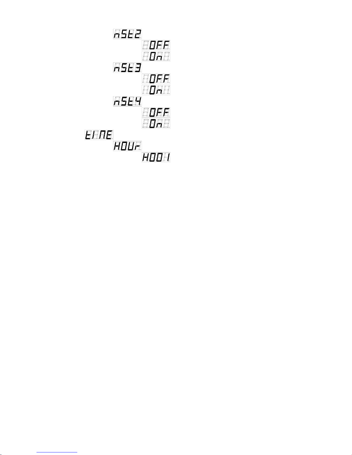
(RESERVED)
(RESERVED)
(RESERVED)
MASTER MODE 4
MASTER MODE 3
MASTER MODE 2
eg."H001" MEANS 1 HOUR
DISPLAY TIME
HOUR
OFF
ON
OFF
ON
OFF
ON
Pilot 1200 manual.doc
8/20
Page 9
ERRORS DISPLAY
In the course of launch, PILOT 1200 examines automatically whether there are errors and if there are,
it will display information as follows:
INFORMATION ERRORS
Er02 Sensor 1 temperature too high
Er04 Lamp error
Er05 EEPROM error
Er06 Sensor 2 temperature too high
Er09 Gobo rotation reset error
Er10 Gobo change reset error
Er11 Effect wheel reset error
Er12 Colour wheel reset error
Er17 Prism rotation reset error
Er18 Prism change reset error
Er20 Fixed gobos reset error
Er25 Pan motor reset error
Er26 Tilt motor reset error
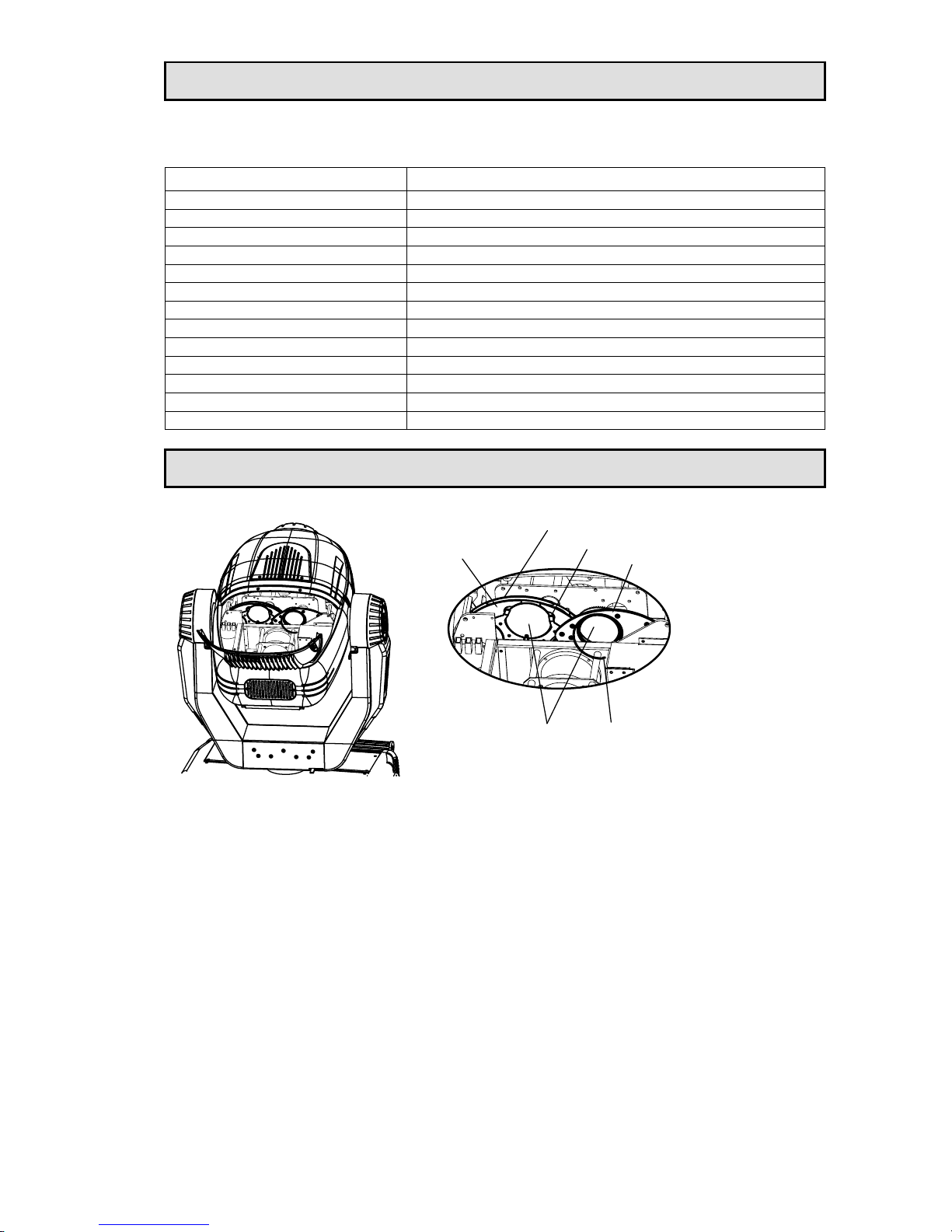
REPLACING GOBOS
PINCERS
ROTATED GOBO WHEEL
RETAINING SPRING
GOBOS
EFFECT WHEEL
FIXED GOBO WHEEL
Lock Tilt. Loosen 2 screws on the rear cover with fans and open the rear cover with fans. You could
see the structure as shown in the above figure.
For gobos replacement on the fixed gobo wheel: turn the effect wheel and rotated gobo wheel to a
proper position first; take out a gobo from the fixed gobo wheel carefully; fit a new gobo. Note: if the
gobo is a glass one, it should be touched with glabrous, clean and soft tissue or cloth matted between
hand and glass instead of with bare hand.
For filters replacement on the effect wheel: do in the same way of fixed gobo wheel.
For gobos replacement on the rotated gobo wheel: take an appropriate tool to tug the head of
retaining spring up and engage your another hand to take the retaining spring out; take the gobo out;
fit a new gobo and fit the retaining spring. Notes: the gobo cannot be touched with bare hand; never
attempt to dismantle the gobo holder on which you want to replace the gobo; be careful of the gobo
when the replacement is underway and don’t drop it.
Close the rear cover and fasten 2 M5 screws.
Pilot 1200 manual.doc
9/20
Page 10
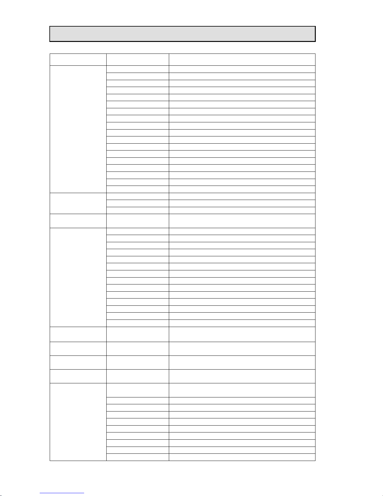
The PILOT 1200 uses 22 DMX channels. They are listed in the following table.
Pilot 1200 manual.doc
10/20
CHANNEL DMX DESCRIPTION
000-009 Shuttering
010-024 White
025-039 Strobe 1
040-054 Strobe 2
055-069 Strobe 3
070-084 Strobe 4
085-099 Strobe 5
100-114 Strobe 6
115-129 Strobe 7
130-144 Strobe 8
145-159 Strobe 9
160-174 Strobe 10
175-189 Strobe 11
190-204 Strobe 12
205-219 Strobe 13
220-234 Strobe 14
235-249 Strobe 15
1
Strobe
250-255 White
000-009 Black
010-024 Open
2
Dimmer
025-255 Dimming from light to dark (0-100%)
3
Iris
000-255
Linearly adjust iris from large to small (0=wholly
open; 100=wholly closed)
000-031 White
032-063 Gobo 1
064-095 Gobo 2
096-127 Gobo 3
128-159 Gobo 4
160-167 Rotation speed 1 (slowest)
168-175 Rotation speed 2
176-183 Rotation speed 3
184-191 Rotation speed 4 (fastest)
192-223 Stop rotating
224-231 Reverse rotation speed 1 (slowest)
232-239 Reverse rotation speed 2
240-247 Reverse rotation speed 3
4
Fixed Gobo
248-255 Reverse rotation speed 4 (fastest)
5
Pan
000-255 Pan rotation
6
Tilt
000-255 Tilt rotation
7
Focus
000-255 Linearly focusing
8
Zoom
000-255 Zooming with spot from large to small
000-024
White. Note: stay 5 seconds while DMX value is 5, 6
or 7, the function reset perform
025-030 White/colour filter 1
031-036 Colour filter 1
037-042 Colour filter 1/colour filter 2
043-048 Colour filter 2
049-054 Colour filter 2/colour filter 3
055-060 Colour filter 3
061-065 Colour filter 3/colour filter 4
066-071 Colour filter 4
9
Colour Wheel
072-077 Colour filter 4/colour filter 5
DMX CONTROL CHANNEL FUNCTIONS
Page 11

Pilot 1200 manual.doc
11/20
078-083 Colour filter 5
084-089 Colour filter 5/colour filter 6
090-095 Colour filter 6
096-101 Colour filter 6/colour filter 7
102-107 Colour filter 7
108-113 Colour filter 7/white
114-121 Rotation speed 1 (fastest)
122-129 Rotation speed 2
130-137 Rotation speed 3
138-145 Rotation speed 4
146-153 Rotation speed 5
154-161 Rotation speed 6
162-169 Rotation speed 7
170-177 Rotation speed 8 (slowest)
178-191 Stop rotating
192-199 Reverse rotation speed 8 (slowest)
200-207 Reverse rotation speed 7
208-215 Reverse rotation speed 6
216-223 Reverse rotation speed 5
224-231 Reverse rotation speed 4
232-239 Reverse rotation speed 3
240-247 Reverse rotation speed 2
248-255 Reverse rotation speed 1 (fastest)
10
CYM-Cyan
000-255 Cyan (0-100%)
11
CYM-Yellow
000-255 Yellow (0-100%)
12
CYM-Magenta
000-255 Magenta (0-100%)
000-050 White
051-101 Gobo 1
102-152 Gobo 2
153-203 Gobo 3
13
Rotating Gobo
204-255 Gobo 4
000-119
Gobo index(0~540°)
120-127 Rotation speed 1 (fastest)
128-135 Rotation speed 2
136-143 Rotation speed 3
144-151 Rotation speed 4
152-159 Rotation speed 5
160-167 Rotation speed 6
168-175 Rotation speed 7
176-183 Rotation speed 8 (slowest)
184-191 Stop rotating
192-199 Reverse rotation speed 8 (slowest)
200-207 Reverse rotation speed 7
208-215 Reverse rotation speed 6
216-223 Reverse rotation speed 5
224-231 Reverse rotation speed 4
232-239 Reverse rotation speed 3
240-247 Reverse rotation speed 2
14
Gobo Rotation
248-255 Reverse rotation speed 1 (fastest)
000-050 White
051-101 Prism 1
102-152 Prism 2
153-203 Prism 3
15
Prism
204-255 Prism 4
000-119
Index(0~540°)
120-127 Rotation speed 1 (fastest)
128-135 Rotation speed 2
16
Prism Rotation
136-143 Rotation speed 3
Page 12
144-151 Rotation speed 4
152-159 Rotation speed 5
160-167 Rotation speed 6
168-175 Rotation speed 7
176-183 Rotation speed 8 (slowest)
184-191 Stop rotating
192-199 Reverse rotation speed 8 (slowest)
200-207 Reverse rotation speed 7
208-215 Reverse rotation speed 6
216-223 Reverse rotation speed 5
224-231 Reverse rotation speed 4
232-239 Reverse rotation speed 3
240-247 Reverse rotation speed 2
248-255 Reverse rotation speed 1 (fastest)
000-050 White
051-101 Effect 1
102-152 Effect 2
153-203 Effect 3
17
Effects Wheel
204-255 Effect 4
18
Frost
000-255 Frosting from slight to strong (0~100%)
19
Pan & Tilt Speed
000-255 Pan&Tilt speed adjustable by steps from fast to slow
20
Pan Fine
000-255 Pan rotation in 16 Bit precision
21
Tilt Fine
000-255 Tilt rotation in 16 Bit precision
000-170 Lamp ON (Reserved) 22
Control
171-255 Lamp OFF after 10 seconds or over (Reserved)
LED DISPLAY
Green: ON——DMX signal OK or Slave;
OFF——No DMX signal;
Flash——DMX error;
Red: Medium flash——Menu mode;
Fast flash——software, cpu error;
Both ON: Address mode,
Flash in turn: Master mode.
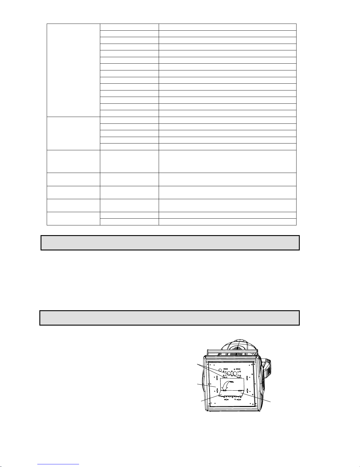
CHANGING BELTS
Pilot 1200 manual.doc
12/20
Pan’s belts
Free 2 screws on Pan assembly’s
maintenance door and open the door;
change the belts; close the door and fasten
the screws.
maintenace door
Pan assembly's
Open the door
Screws
Base
Tilt’s belts
The common users replacing the belts is not
recommended.
Page 13

MAINTENANCE
If the projector’s lens becomes damaged or broken it should be replaced. If the lamp becomes
damaged or deformed in any way it must be replaced. If the light from the lamp appears dim this would
normally indicate that it is reaching the end of its life and it should be changed at once, aged lamps
run to the extremity of their life might explode. If the projector does not function, check the fuses on
the power socket of the projector, they should only be replaced by fuses of the same specification
6.35X32 T15A/250V. On the PCBs inside the projector there are also 3 fuses. They are 2 fuses 6.3A
/250V (fast blow,5mmx20mm) on both Pan PCB and Tilt PCB, 1 fuse 4A/250V (fast blow,
5mmx20mm) on driver PCB. Should these be damaged call a qualified technician before replacement.
The projector has thermal protection device that will switch off the projector in case of overheating,
should either of these operate, check that the fans are not blocked, and if they are dirty clean them
before switching on the projector again. Check that the fans are operational, if not call a qualified
technician.
Any maintenance work should only be carried out by qualified technicians.
To ensure the continuous rotation of the rotating gobos and linear motion of the lens for focusing, it is
recommended that the bearings for the rotating gobos and the 2 shafts for the focusing lens holder be
lubricated periodically, preferably every two months. Use only high quality, high-temperature resistant
grease instead of any type of oil. When lubricating the bearings, a syringe with a fine needle is the
easiest way to introduce the grease to the bearings around each gobo.
LUBRICATION
KEEPING THE PROJECTOR CLEAN
To ensure the reliability of the projector it should be kept clean. It is recommended that the fans should
be cleaned every 15 days. The lens and dichroic colour filters should also be regularly cleaned to
maintain an optimum light output.
Do NOT use any type of solvent on dichroic colour filters.
Cleaning frequency depends on the environment in which the fixture operates: damp, smoke or
particularly dirty surroundings can cause greater accumulation of dirt on the unit’s optics. A soft cloth
and typical glass cleaning products should be used in cleaning. It is recommended to clean the
external optics at least once every 20 days and clean the internal optics at least once every 30 / 60
days.
Do not use any organic solvent, e.g. alcohol, to clean the reflector mirror, dichroic colour filters
or housing of the apparatus.
Pilot 1200 manual.doc
13/20
Page 14
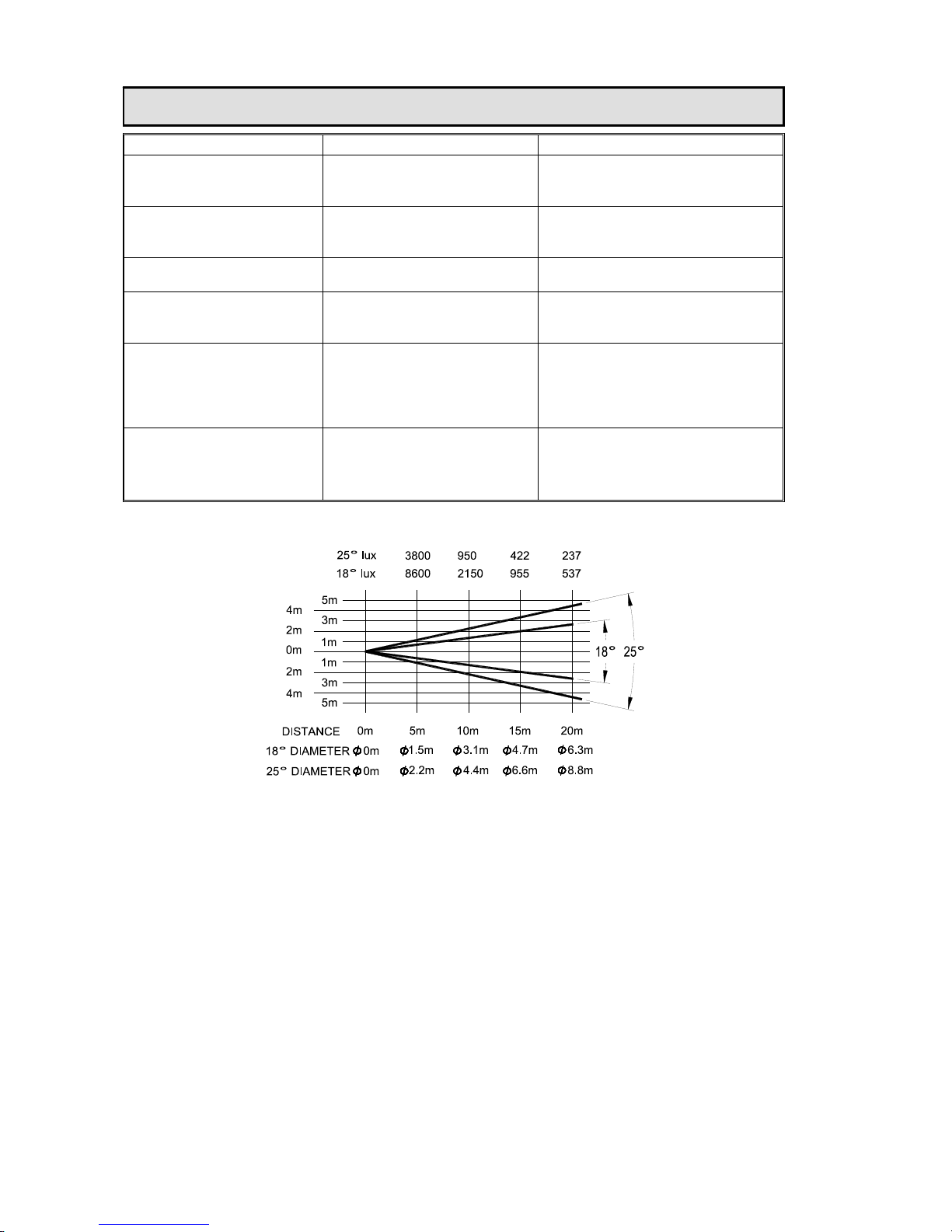
TROUBLESHOOTING
PROBLEM POSSIBLE CAUSE ACTION
The projector doesn’t switch
on
-The power supply is not
present
-The lamp doesn’t work
Check the fuse on the power
socket.
Replace the lamp.
The lamp comes on but the
projector doesn’t respond to
the controller
-Wrong DMX configuration
and/or start address
- Defective DMX cable
Make sure that the projector is
correctly configurated.
Replace or repair the DMX cable.
The projector only functions
intermittently
-The fan has failed Make sure the fan is working and
not dirty.
Defective projection -The lens is broken
-Dust or grease on lenses
Check the lenses are not broken.
Remove dust or grease from the
lenses.
The projected image
appears to have a halo
-Installation of the lamp is not
correct
-Dust or grease contamination
on the optics.
Make sure the lamp is installed
correctly.
Carefully clean the optical group
lenses and the projector
components.
The beam appears dim -Dust or grease contamination
on the optics.
-The lamp is at the end of its
life
Check the optics is clean.
Replace with a new lamp of the
specified type and rating.
LIGHT OUTPUT
Pilot 1200 manual.doc
14/20
Page 15

TECHNICAL DATA
VOLTAGES:
200/220/230/240V AC, 50Hz or 60Hz
POWER CONSUMPTION:
1628W@230V
LAMP:
Type: HTI 1200W/S discharge lamp
Colour Temperature: 6000ºK
Socket: SFc10-4
Manufacturers Rated Lamp Life: 750 Hours
COLOURS:
CYM colour mixing system
1 wheel with 7 fixed Dichroic colours plus white
With variable speed bidirectional rainbow effect
COLOUR TEMPERATURE CORRECTION:
2 colour temperature correction filters
GOBOS:
Rotating gobo wheel
4 interchangeable gobos+white, indexable, bidirectionally rotating at variable
speeds.
Fixed gobo wheel
4 interchangeable gobos+white, the fixed gobo wheel can scroll in eather
direction at variable speeds.
Both glass gobos and metal gobos may be fitted to either wheel.
Gobo diameter: Φ51.8mm
Gobo image diameter: Φ48mm
PRISM:
1x2 facet, 1 x 3 facet, 1x5 facet, 1 x linear prisms, indexable, bidirectionally
rotating at variable speeds
FOCUS:
DMX controlled focus
EFFECT FILTERS:
1 ultraviolet filter and 1 bicolour filter
FROST:
Variable frost effect, 0-100% linearly adjustable
SHUTTER:
Double shutter blades, 0-100% linearly adjustable
STROBE:
1 – 7 F.P.S.
HEAD MOVEMENT:
Pan 540º, Tilt 270º
BEAM ANGLE:
18º--25º linear zoom
CONTROL:
DMX512, 20 channels plus 2 channels for high resolution Pan and Tilt
Pilot 1200 manual.doc
15/20
Page 16
OTHER FUNCTIONS:
Adjustable Pan & Tilt speed, Projector usage time display, lamp time display.
HOUSING:
Metal and composite plastic (IP20)
WEIGHT:
54Kg.
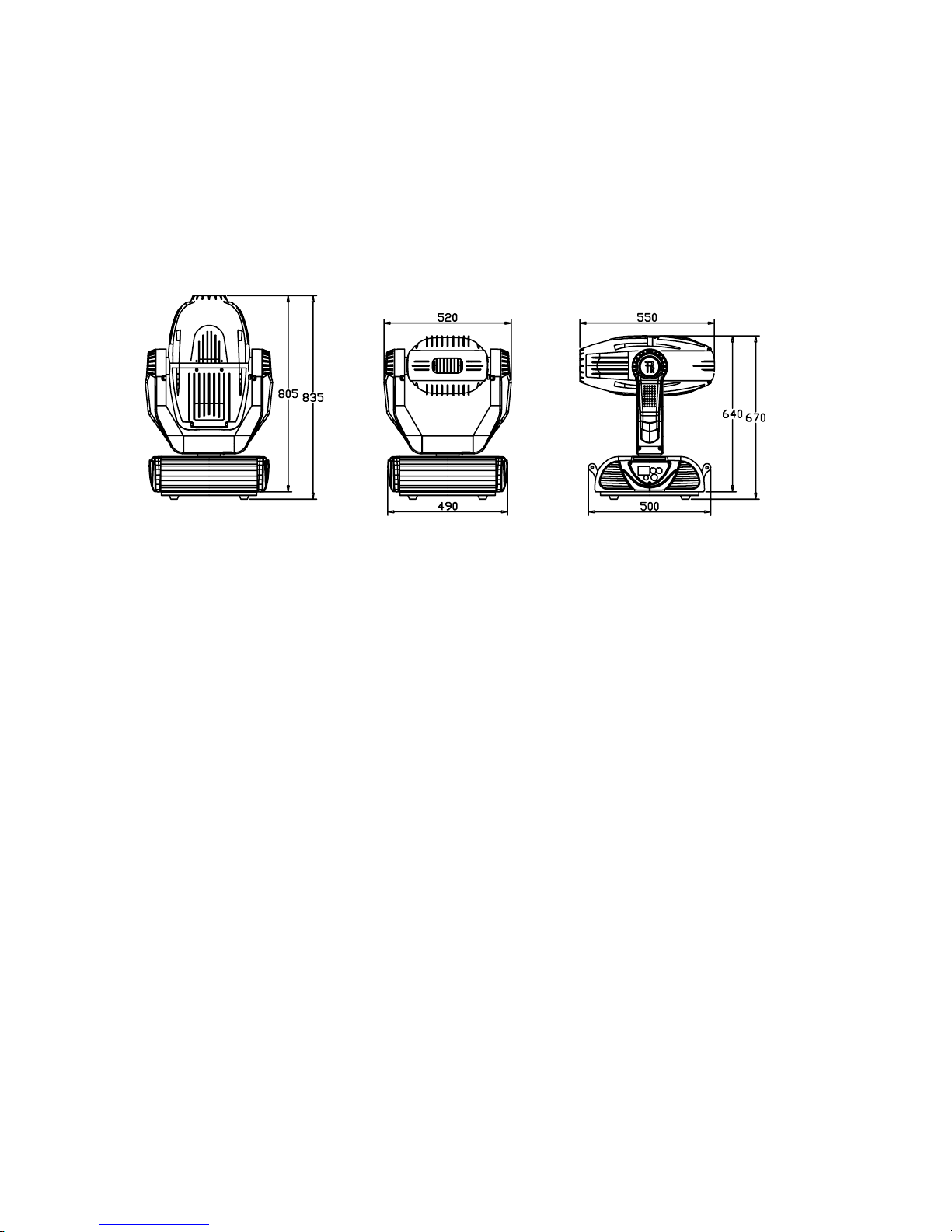
SIZES:
See Drawings
Pilot 1200 manual.doc
16/20
Page 17
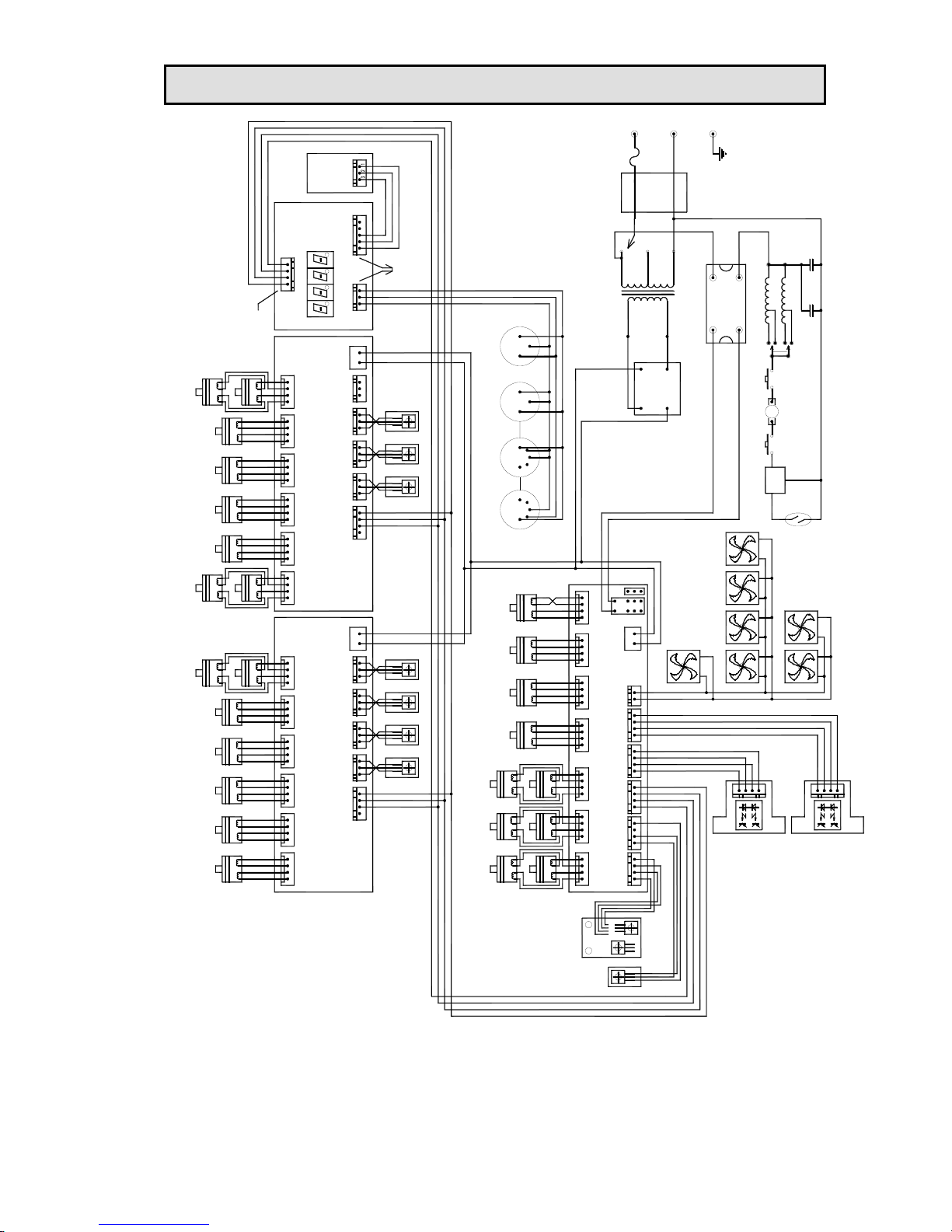
ELECTRICAL DIAGRAM
PCB
Thermostat
(200/220/240V)
-
+
-
+
-
+
-
+
-
+
-
+
+
-
+
-
+
-
N
DL
Ph
50Hz
60Hz
70uF 370V
CAP_1
70uF 370V
CAP_2
Ph
Ballast x 2
60Hz
50Hz
SW-PB
Thermostat
SW-PB
Ignitor
--
OUT
IN
+
Solid state SCR
AC Plug
E
N
L
T15A
Fuse
Filter
0V
230V
Transformer
AC20V
AC
+++
3510
BRIDGE
---
AC
HMI1200W/S
LAMP
DOWN FAN-2DOWN FAN-1
TOP FAN-5TOP FAN-4TOP FAN-3TOP FAN-2
TOP FAN-1
7PCS FAN (DC24V)
TILT ENCODE
PAN ENCODE
-+
DC 20V
TILTPAN
FAN+
FAN-
GND
S1
S2
VCC
VCC
S2
S1
GND
+5V
DATA B
DATA A
GND
+
SENS
-
-
SENS 1
SENS 2
+
PAN-HALL
TILT-HALL
2
1
3
1
5
3
3
2
1
5
3
1
DMX-IN
DMX-OUTDMX-OUT
DMX-IN
Encoder-Motor No encoder-MotorNo encoder-Motor
DCBADCBADCBA
D
C
BAD
C
BAD
C
BAD
C
BA
D
C
BAD
C
BAD
C
BA
TILT-2TILT-1PAN-2
Encoder-Motor
PAN-1
CYM-MCYM-YCYM-C
HALLHALLHALLHALLHALLHALLHALL
place back
+5V
SENS1
GND
SENS3
SENS2
312
GND
D- - D++
place back
+5V
DATA B
DATA A
GND
DMX
-+
DC 20V
+-
DC 20V
2# PCB
FIX GOBO
RUOT PRISM
PRISM
COLOR
EFECT
RUOT GOBO
GOBO
1# PCB
sens
-
+5V
DATA B
DATA A
GND
sens
+
+
-
sens
+
-
sens
+
sens
+
sens
+
sens
+
+
-
sens
GND
DATA A
DATA B
+5V
DMX
D
C
BA
DCBA
D
C
BA
DCBA
D
C
BA
DCBA
DCBADCBADCBADCBAABCD
AB
C
DAB
C
DAB
C
DAB
C
DAB
C
DAB
C
DAB
C
DAB
C
D
SHUTTER
FOBO FIX
D
C
BA
ZOOMFROST
IRISPRISMRUOT PRISMFOCUSCOLOREFFECTGOBORUOT GOBO
Pilot 1200 manual.doc
17/20
Page 18
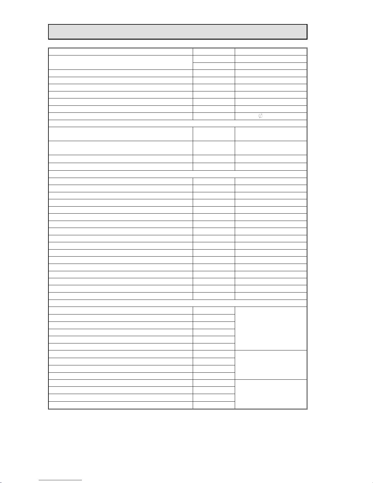
COMPONENT ORDER CODES
NAME PART NO. REMARK
040030054 200/240V
TRANSFORMER
040030056 220/230V
THERMOSTAT 190010035 KSD020 120/15A/250V
CAPACITOR 140010043 70µF/370V
BALLAST 040070059 230V/50-60Hz, 575W
IGNITOR 040090036 575~1200W 6~8KV
LAMP 100050013 HMI 1200W/S
PAN&TILT DRIVE BELT1, 2, 3 290151221 HTD459-3M-6
“O” Belt 290151302
100x3.1
FANS
FAN1,2 in strobe(SUNNO)
030060031
KDE2408PTB1-6
24VDC
FAN3 in strobe(SUNNO)
030069005
KD2406PTS1
DC24V\2.6W
FAN4,5 on the rear cover 030060039
CIC-100(S-1)
FAN6,7 in base(SUNNO)
030060035 KDE2409PTB-6 24VDC
MOTORS
MOTOR 1,2 (PAN) 030040089 23HS2039L
MOTOR 3,4 (TILT) 030040068 23HS0001-07L
MOTOR 5,6 (SHUTTER BLADE) 030040084 17HS0002-59L
MOTOR 7 (PRISM) 030040085 17HS0002-61L
MOTOR 8 (PRISM) 030060099
MOTOR 9 (PRISM ROTATION) 030040085 17HS0002-61L
MOTOR 10 (FIXED GOBO WHEE) 030060098
MOTOR 11 (COLOUR WHEEL) 030040084 17HS0002-59L
MOTOR 12 (ROTATING GOBO WHEEL) 030040098
MOTOR 13 (GOBO ROTATION) 030040084 17HS0002-59L
MOTOR 14 (FOCUS) 030040083 17HS0002-60L
MOTOR 15 (EFFECT WHEEL) 030040083 17HS0002-60L
MOTOR 16,17 (ZOOM) 030040083 17HS0002-60L
MOTOR 18,19 (FROST) 030040060 16HY0002-02L
MOTOR 20,21 (CYM-YELLOW) 030040061 16HY0002-03L
MOTOR 22,23 (CYM-CYAN) 030040061 16HY0002-03L
MOTOR 24,25 (CYM-MAGENTA) 030040060 16HY0002-02L
CHIPS
IC1, 2, 3 (NJM3771D2 或 PBL3771)
170110004
IC4, 5, 6, 7 (NJM3772D2) 170110019
IC8 (MB88346B) 170170056
IC9 (CM2576/5V) 170170057
IC10 (MAIN CPU) 230040161
IC11 (MINOR CPU) 230040162
Pan & Tilt driver PCB
IC12, 13, 14, 15, 16, 17 (NJM3771D2 或 PBL3771)
170110004
IC18 (LM2574N-5) 170170039
IC19 (MB88346B) 170170056
IC20 (CPU) 230040163
Motor driver PCB Ⅰ
Motor driver PCB Ⅱ
IC21 (CPU) 230040159
IC22 (MCP100-450) 170040035
IC23 (DS75176BN 或 SN75176BP)
170170012
IC24 (24LC256) 170170058
Digital PCB
NOTE: You may order all parts of the PILOT 1200 besides the table listed above. When ordering
please state the exact name and part no. Repairs must be carried out by a qualified technician.
Pilot 1200 manual.doc
18/20
Page 19
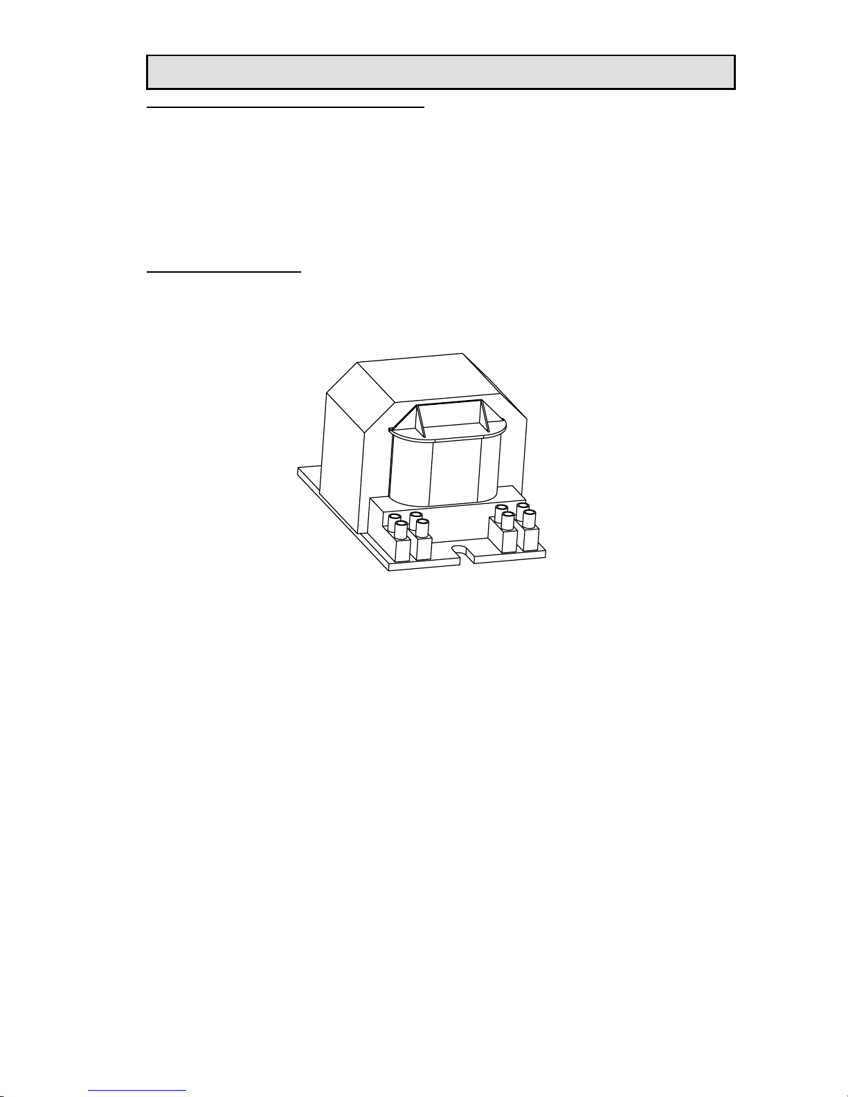
To be carried out by qualified engineers only
CHANGING THE OPERATION VOLTAGE AND/OR FREQUENCY
The power input setting of the PILOT 1200 may be changed to suit the supply in your area that the
unit is to be operated. The voltage and frequency are pre-set at the factory and marked on the
exterior of the unit.
Any error or mistake in setting the voltage or frequency of the projector may seriously damage the
unit.
Make sure the specifications of the transformer match the power supply and if not, the suitable
transformer must be ordered (see the data).
It is strongly recommended that you immediately mark the new frequency on the projector so that it
may not be mistaken for the factory set frequency.
To change the frequency
Open the base of the projector by unscrewing the eight screws on the top of the base and do the
following operation.
Locate the ballast in the base of the projector, and select the required frequency from 50Hz or 60Hz
by moving the cable to the appropriate position. The ballast will be labeled to show the connections.
Never move or disconnect the cable attached to the connector marked “L”.
6
0
H
z
L
5
0
H
z
Once finished with the settings, re-assemble covers.
Pilot 1200 manual.doc
19/20
Page 20

PR LIGHTING LTD.
No. 571, Yingbin Road, Dashi, Panyu, Guangzhou, China
Post-Code: 511430
TEL: +86-20-8478 1888
FAX: +86-20-8478 6023
Pilot 1200 manual.doc
20/20
P/N: 321010221
Last Revision: 10:08:2004
 Loading...