

Page 1
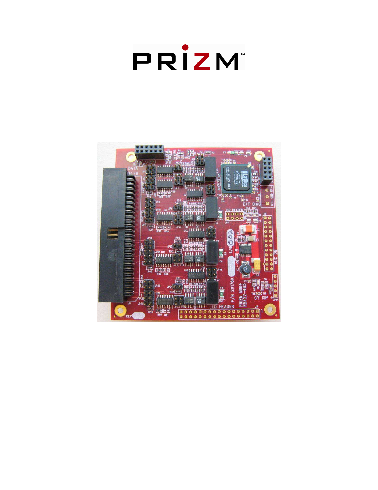
8-Port RS-422/485 Daughterboard (P/N 201760-xxx)
User’s Manual
And
Troubleshooting Guide
February 24, 2009
Springfield, PA 19064
E-Mail: mcg@moog.com URL: www.moog.com/components
24/7 Technical Customer Support Hotline: 610-605-6101
Rev. B
Moog Components Group
Springfield Operations
750 West Sproul Road
Tel: 610-328-4000 Fax 610-605-6216
Page 2

Moog Components Group 201760 - RS-422/485 Daughterboard 2/24/2009
TABLE OF CONTENTS
1 RS-422/485 Daughterboard, Part Number 201760-xxx. ........................................................................ 3
1.1 RS-422/485 Daughterboard Revision History: .............................................................................. 3
1.2 RS-422/485 Daughterboard Dash (-) Number Definitions ............................................................. 3
1.3 Manual Revision History:............................................................................................................... 3
1.4 RS-422/485 Daughterboard Operation: .......................................................................................... 4
2 Connectors.............................................................................................................................................. 4
3 RS-422/485 Daughterboard Troubleshooting......................................................................................... 6
4 RS-422/485 Daughterboard Board Level Testing .................................................................................. 7
4.1.1 RS-422/485 Daughterboard Data Loop-Back Test ................................................................. 7
4.1.2 Test Data Channels ................................................................................................................. 7
5 RS-422/485 Daughterboard – Auxiliary Daughterboard Options .......................................................... 8
6 Jumper Configuration Table................................................................................................................... 9
Page 2 of 9
Page 3

Moog Components Group 201760 - RS-422/485 Daughterboard 2/24/2009
1 RS-422/485 Daughterboard, Part Number 201760-xxx.
The Prizm RS-422/485 daughterboard provides eight (8) RS-422 or RS-485 pair-wise
isolated data channels that are multiplexed onto a single Prizm high-speed serial data
channel onto Mini4 or MiniMux2 Motherboard. Daughterboard channel selection of RS-422
or RS-485 can be simply done by selecting a few jumper posts and can be accomplished on
a channel-by-channel basis for mixed data applications. Please refer to the table to for
appropriate jumper configuration. With an additional pluggable auxiliary daughter board,
more independent serial channels can be carried. The combinations of types of channels
(RS-232, RS-422, and/or RS-485) will vary depending on the type and configuration of
daughterboards. Up to two (2) RS-422/485 daughterboards can be used on a Mini4 system.
MiniMux2 only supports one (1) daughterboard.
Each pair of RS-422/485 data channels are electrically isolated and independently powered.
Each RS-422/485 channel can support up to 115.4 Kilobaud.
1.1 RS-422/485 Daughterboard Revision History:
The Submux3 motherboard has gone through the following printed circuit board (PCB) and
Assembly revisions:
PCB Revision A/Assembly Revision A Original design
1.2 RS-422/485 Daughterboard Dash (-) Number Definitions
The daughterboard has a Dash Number appended to the part number. This Dash Number
identifies the specific board configurations:
-001 Original configuration.
-002 With LED Display Header J7 placed
1.3 Manual Revision History:
The manual has gone through the following revisions:
Revision A Preliminary
Revision B Updated contact information to reflect Moog Components Group
Page 3 of 9
Page 4

Moog Components Group 201760 - RS-422/485 Daughterboard 2/24/2009
1.4 RS-422/485 Daughterboard Operation:
On Mini4 and MinMux2 systems, the daughterboard is connected to the motherboard via
the 12-pin motherboard connector. Individual serial channels are multiplexed on the
daughterboard and interfaced to the motherboard as a single high-speed serial link.
2 Connectors
J6 – Data Connector
There is 50-pin dual-row rectangular Amp connector on the on the front of the
daughterboard.
Mfg p/n – 2-103167-2
Mating Connectors
AMP p/n - 4-87631-1 (Prizm p/n CN0314) type- unstamped
AMP p/n – 4-87631-2 (Stamped)
AMP p/n – 4-87631-2 (Stamped with strain relief)
Signal Name Pin Pin Signal Name
R1+ 1 2 T1+
GND_ISO_A 3 4 GND_ISO_A
R1- 5 6 T1-
R2+ 7 8 T2+
GND_ISO_A 9 10 GND_ISO_A
R2- 11 12 T2-
Isolation barrier Isolation barrier
R3+ 13 14 T5+
GND_ISO_B 15 16 GND_ISO_B
R3- 17 18 T3-
R4+ 19 20 T4+
GND_ISO_B 21 22 GND_ISO_B
R4- 23 24 T4-
Isolation barrier Isolation barrier
R5+ 25 26 T5+
GND_ISO_C 27 28 GND_ISO_C
R5- 29 30 T5-
R6+ 31 32 T6+
GND_ISO_C 33 34 GND_ISO_C
R6- 35 36 T6-
Isolation barrier Isolation barrier
R7+ 37 38 T7+
GND_ISO_D 39 40 GND_ISO_D
R7- 41 42 T7-
R8+ 43 44 T8+
GND_ISO_D 45 46 GND_ISO_D
R8- 47 48 T8-
N/C 49 50 N/C
Page 4 of 9
Page 5

Moog Components Group 201760 - RS-422/485 Daughterboard 2/24/2009
J1
VDC Supply 1 o o 2 VDC Supply
RCV LINK 9 o o 10 Future
RXC_DB2 11 o o 12 TXC_DB2
Motherboard
Connector
RXD_DB 3 o o 4 TXD_DB
GND 5 o o 6 GND
RXC_DB 7 o o 8 TXC_DB
J2
Diagnostics
Header
RT+ 1 o o 2 RTGND 3 o o 4 GND
GND 5 o o 6 GND
+5V 7 o o 8 +5V
+5V 9 o o 10 +5V
J3 – Diagnostics Connector
Pin 1 – RT+
Pin 2 – GND
Pin 3 – RT-
J4 – ISP Header (Not Customer Accessible)
J5 – Auxiliary Daughterboard Connector
Signal Name Pin Pin Signal Name
+5V 1 2 +5V
RX9 3 4 TX9
RX10 5 6 TX10
RX11 7 8 TX11
RX12 9 10 TX12
RX13 11 12 TX13
RX14 13 14 TX14
GND 15 16 GND
SYNC_IN 17 18 FUTURE_AUX_DB
RT+ 19 20 RTRX15 21 22 TX15
RX16 23 24 TX16
Page 5 of 9
Page 6

Moog Components Group 201760 - RS-422/485 Daughterboard 2/24/2009
J7 – LED Header
Signal Name Pin Pin Signal Name
GND 1 2 +5V (optional)
R1 3 4 T1
R2 5 6 T2
R3 7 8 T3
R4 9 10 T4
R5 11 12 T5
R6 13 14 T6
R7 15 16 T7
R8 17 18 T8
19 20
21 22
23 24
25 26
27 28
29 30
31 32
33 34
3 RS-422/485 Daughterboard Troubleshooting
In normal operation the following board mounted LED status should be observed:
D1
D9
D10
D8
LED9
LED1
LED2
LED3
+5VDC power LED Lit green
RLINK LED - Lit green if receiving link from Modem
TLINK LED - Lit green if receiving link from Modem
+3.3VDC power LED Lit green
Channels 1&2 Isolated +5VDC power - LED Lit green
Channels 3&4 Isolated +5VDC power - LED Lit green
Channels 5&6 Isolated +5VDC power - LED Lit green
Channels 7&8 Isolated +5VDC power - LED Lit green
Page 6 of 9
Page 7

Moog Components Group 201760 - RS-422/485 Daughterboard 2/24/2009
RS-422/485 Data Activity LEDs
In normal operation with data traffic the following right angle bi-color LEDs, mounted on
the edge of the board (under the data connector) should be observed:
D32
D30
D26
D25
D22
D19
D17
D14
Channel 1 lit RED for Tx, lit GREEN for Rx
Channel 2 lit RED for Tx, lit GREEN for Rx
Channel 3 lit RED for Tx, lit GREEN for Rx
Channel 4 lit RED for Tx, lit GREEN for Rx
Channel 5 lit RED for Tx, lit GREEN for Rx
Channel 6 lit RED for Tx, lit GREEN for Rx
Channel 7 lit RED for Tx, lit GREEN for Rx
Channel 8 lit RED for Tx, lit GREEN for Rx
4 RS-422/485 Daughterboard Board Level Testing
i. If DC power +5V LED (D1) is out:
• Make sure +5VDC is available at the motherboard connector J1.
• Check 2Amp fuse (F1) with ohmmeter, replace with another fuse if blown
ii. If DC power 3.3 LED (D8) is out:
• Problem with the 5V to 3.3V DC-DC converter circuit on the board. Not field
serviceable. Replace the board.
iii Faulty isolated power supply for channel pairs:
• LED9 – Out Ch1&2 will not work
• LED1 – Out Ch3&4 will not work
• LED2 – Out Ch5&6 will not work
• LED3 – Out Ch7&8 will not work
4.1.1 RS-422/485 Daughterboard Data Loop-Back Test
With a daughterboard in both the vehicle (ROV) and surface units, run RS-422 data into
pins 1 (+) and 5 (-) of the connector of channel 1 (as an example) being tested. The RS-422
data can be input into either the ROV or surface board. Connect the Rx to pins 2 and 6.. On
the other end of the link, short pins 1 and 2 (the positive signals) and pins 5 and 6 (the
negative signals) of the daughterboard channel 1 being tested. This process can be repeated
on every channel of the board. This will allow the two daughterboards to talk to each other
in loopback. Both RX and TX LEDs on both boards should be lit and/or flickering. If any
of the LEDs are not operating, check one of the other channels. If the LEDs operate on that
channel, replace daughterboard with a spare board or use the working channels only.
4.1.2 Test Data Channels
If an appropriate serial data test generator is available (or a PC with Communications
software, or even a square wave generator) the individual channels can be tested on a
Page 7 of 9
Page 8

Moog Components Group 201760 - RS-422/485 Daughterboard 2/24/2009
channel-by-channel basis. This test can be done for all channels on the daughterboard. The
user must be sure that the test signal levels are compatible with the interface/channel being
tested.
5 RS-422/485 Daughterboard – Auxiliary Daughterboard
Options
The Prizm 8-channel RS-422/485 daughterboard supports 8 pair wise isolated RS-422/485
serial data channels, when plugged onto a Mini4 motherboard. Up to a total of 2 daughter
boards may be stacked on one motherboard. The maximum data rate that this board supports
is 115Kbaud. 201760 daughterboard can be intermixed with the 16-channel RS-232
daughterboard (Prizm p/n - 210610) or used with a Tritech Trigger/Responder (Prizm p/n
– 201600) board as its auxiliary daughterboard. Custom boards auxiliary boards for this
daughterboard would be designed in the future per customer requirements.
Page 8 of 9
Page 9

Moog Components Group 201760 - RS-422/485 Daughterboard 2/24/2009
6 Jumper Configuration Table
Ch1
RS-422 RS-485
No Jumpers
Placed
JP 22 & JP 23
RS-485
with 100 Ω termination
JP 25
Ch2
Ch3
Ch4
Ch5
Ch6
No Jumpers
Placed
No Jumpers
Placed
No Jumpers
Placed
No Jumpers
Placed
No Jumpers
Placed
JP 20 & JP 19
JP 16 & JP 18
JP 14 & JP 13
JP 10 & JP 12
JP 8 & JP 7
JP 21
JP 17
JP 15
JP 11
JP 9
No Jumpers
Placed
Ch7
No Jumpers
Placed
Ch8
Page 9 of 9
JP 4 & JP 5
JP 2 & JP 1
JP 6
JP 3
 Loading...