

Page 1

Prizm 4 Port 10/100/1000 Mbps Ethernet Switch
(P/N: 201640-xxx)
Users’ Manual
And
Troubleshooting Guide
February 23, 2009
Rev. C
Moog Components Group
Springfield Operations
750 West Sproul Road
Springfield, PA 19064
E-Mail: mcg@moog.com URL: www.moog.com/components
Tel: 610-328-4000 Fax 610-605-6216
24/7 Technical Customer Support Hotline: 610-605-6101
Page 2

Moog Components Group 4 Port 10/100/1000 Mbps Ethernet Switch February 23, 2009
(201640-xxx)
TABLE OF CONTENTS
1 Prizm 4 Port 10/100/1000 Mbps Ethernet Switch (P/N: 201640-xxx) Overview ............................................................3
1.1 4 Port 10/100/1000 Mbps Ethernet Switch Revision History:………………………………………........................3
1.2 4 Port 10/100/1000 Mbps Ethernet Switch Dash (-) Number Definitions:………………………………………….3
1.3 4 Port 10/100/1000 Mbps Ethernet Switch Operation………………………………………………………………3
1.4 4 Port 10/100/1000 Mbps Ethernet Switch Indicators and Controls………………………………………………...5
1.5 4 Port 10/100/1000 Mbps Ethernet Switch Specifications:…………..…………………………………………….10
1.5.1 4 Port 10/100/1000 Mbps Ethernet Switch Dimensions:................................................................................ 10
1.5.2 4 Port 10/100/1000 Mbps Ethernet Switch Power Requirements ..................................................................10
1.6 Power Section Testing……………………………………………………………………………………………...11
1.7 Optical Section Testing…………………………………………………………………………………………….11
1.8 DIAGNOSTIC OVERVIEW………………………………………………………………………………………12
1.9 Communications Hardware………………………………………………………………………………………...12
Page 2 of 13
Page 3

Moog Components Group 4 Port 10/100/1000 Mbps Ethernet Switch February 23, 2009
(201640-xxx)
1 Prizm 4 Port 10/100/1000 Mbps Ethernet Switch (P/N: 201640-
xxx) Overview
The 4 Port 10/100/1000Mbps Ethernet Switch is designed to be used as one of a pair to provide a 1Gbps
Ethernet fiber optic data link between two 4 port switches. Each board is functionally identical to the
corresponding board at the opposite end of the link. The only difference between the two boards, on
occasion, is the wavelength of the transmitting laser. By using a different wavelength for each transmitter
in the pair, bidirectional, full-duplex communication can be achieved over a single fiber optic cable. Each
of the ports on the switch independently supports communication at 10, 100, or 1000Mbps and is 802.3ab
compliant. The switch supports up to 4k unicast MAC addresses. The boards are shipped in a standard
configuration that should be appropriate for most users however, some additional features that can be
provided on an as needed basis include: support for jumbo frames of up to 9728 bytes, port based virtual
LAN, broadcast storm suppression, and port mirroring. Contact Moog Components Group technical
support if you have questions about these or any other features that may be required.
1.1 4 Port 10/100/1000 Mbps Ethernet Switch Revision History:
The 4 Port 10/100/1000 Mbps Ethernet Switch (201640-xxx) has gone through the following printed
circuit board (PCB) revisions:
PCB Revision A Original design. Not currently in production.
PCB Revision B Revised design. Not currently in production.
PCB Revision C Finalized design. Current production revision.
1.2 4 Port 10/100/1000 Mbps Ethernet Switch Dash (-) Number Definitions:
The 4 Port 10/100/1000 Mbps Ethernet Switches have a Dash Number appended to the part number.
This Dash Number identifies the specific board configurations:
-001A Prototype configuration. Obsolete.
-002A Corresponds to rev B PCB revision. Obsolete.
-003A Rev C PCB revision base configuration. Currently in production.
1.3 4 Port 10/100/1000 Mbps Ethernet Switch Operation
The 4 Port 10/100/1000Mbps Ethernet Switch boards provide 4 copper RJ-45 ports suitable for carrying
standard 10/100/1000Mbps Ethernet and a single fiber optic port which operates at up to 1.25Gbps. The
boards also provide the interface for a daughter board connection and a diagnostics port. A block diagram
of the basic 4 Port 10/100/1000 Mbps Ethernet Switch I/O is shown on the following page and it is
explained in the subsequent paragraphs.
Page 3 of 13
Page 4

Moog Components Group 4 Port 10/100/1000 Mbps Ethernet Switch February 23, 2009
(201640-xxx)
The transmit portion (uplink from vehicle to surface) of the 4 Port 10/100/1000 Mbps Ethernet Switch
takes in 4 standard 10/100/1000Mbps Ethernet signals via RJ-45 connectors and processes the received
signals through an onboard Ethernet switch. If needed, packets are routed to the fiber optic transmitter for
delivery to the switch at the opposite end of the link. The receive portion of the 4 Port 10/100/1000 Mbps
Ethernet Switch accepts the optical signal from the remote end of the link, and recovers any Ethernet
packets present. Those packets are then routed, via the onboard Ethernet switch, to the appropriate RJ-45
connector on the board.
The 4 Port 10/100/1000 Mbps Ethernet Switch requires a +5VDC power source provided through the 2pin Phoenix connector at J5. The boards have an on-board 5V to 3.3V, 2.5V and 1.2V converters to
provide power for the components that use those supply voltage.
Page 4 of 13
Page 5

Moog Components Group 4 Port 10/100/1000 Mbps Ethernet Switch February 23, 2009
the top edge of the board.
(201640-xxx)
1.4 4 Port 10/100/1000 Mbps Ethernet Switch Indicators and Controls
LEDS: There are 7 surface mount (SMD) and 4 dual through hole LED indicators on the 4 Port
10/100/1000 Mbps Ethernet Switch. In addition, there are 8 LED indicators that are built into the 4
position RJ-45 connector. The function of each of these LEDs is detailed below:
All LEDs are located on the topside of the 4 Port 10/100/1000 Mbps Ethernet Switch.
LED Indication
Labeled ‘1.2V’, surface mount, located in the middle of
D1
D2
(Green/Green)
This LED is non-functional and does not need to be illuminated for the board to
function properly.
A dual LED located on the top edge of the board next to the optical module. The
top LED, labeled PWR, provides an indication that the power supply to the optical
transceiver is operational. The lower LED, labeled FBR, indicates that the optical
transceiver module has detected the presence of an input signal on the fiber link.
When ‘ON’ indicates that this board has a good level of received optical power
from the remote unit.
D3
(Green/Green)
D4
(Green/Green)
D5
(Green/Green)
D7 (Green)
D8 (Green)
A dual LED located on the top edge of the board next to the optical module. The
top LED, labeled LNK, provides an indication that the onboard MAC and PHY
are communicating properly. The lower LED, labeled DUP, should be
illuminated at all times to indicate that the optical link is functioning in full duplex
mode.
A dual LED located in the upper left corner of the board next to the RJ-45
Ethernet connector. The top LED, labeled DUP1, is illuminated if Port 1 of the
Ethernet Switch is connected in full duplex mode. The lower LED, labeled
DUP3, is illuminated if Port 3 of the Ethernet Switch is connected in full duplex
mode.
A dual LED located in the upper left corner of the board next to the RJ-45
Ethernet connector. The top LED, labeled DUP2, is illuminated if Port 2 of the
Ethernet Switch is connected in full duplex mode. The lower LED, labeled
DUP4, is illuminated if Port 4 of the Ethernet Switch is connected in full duplex
mode.
Labeled ‘2.5V’, surface mount, located on the mid-right of the board. When ‘ON’
indicates the on-board 2.5V converter is operational
Surface mount, located in the middle of the bottom edge of the board. Indicates
that power is being delivered to the Display Board Header (J7).
Page 5 of 13
Page 6

Moog Components Group 4 Port 10/100/1000 Mbps Ethernet Switch February 23, 2009
(201640-xxx)
D9 (Green)
D10 (Green)
D11(Green)
D12 (Green)
Port 1 Left
(Green/Orange)
Port 1 Right
(Green)
Port 2 Left
(Green/Orange)
Labeled ‘3.3V’, surface mount, located in the middle of the bottom edge of the
board. When ‘ON’ indicates the on-board 5V to 3.3V converter is operational
Labeled ‘5V’, surface mount, located in the lower right corner of the board. When
‘ON’ indicates +5V dc is available to the board
RS-485 Diagnostics Tx Data. Illuminated with traffic being transmitted from the
board on the serial diagnostics port.
RS-485 Diagnostics Rx Data. Illuminated with traffic being received into the
board on the serial diagnostics port.
Port 1 Ethernet SPEED LED. This LED will be illuminated GREEN if Port 1 is
communicating at 1000Mbps and ORANGE if the port is communicating at
100Mbps. If this LED is not illuminated but the LINK LED is lit, the port is
communicating at 10Mbps.
Port 1 Ethernet LINK LED. This LED will be illuminated GREEN if a valid
Ethernet device is connected to the port. This LED will flash as data traffic is
transmitted through the port.
Port 2 Ethernet SPEED LED. This LED will be illuminated GREEN if Port 2 is
communicating at 1000Mbps and ORANGE if the port is communicating at
100Mbps. If this LED is not illuminated but the LINK LED is lit, the port is
communicating at 10Mbps.
Port 2 Right
(Green)
Port 3 Left
(Green/Orange)
Port 3 Right
(Green)
Port 4 Left
(Green/Orange)
Port 4 Right
(Green)
Port 2 Ethernet LINK LED. This LED will be illuminated GREEN if a valid
Ethernet device is connected to the port. This LED will flash as data traffic is
transmitted through the port.
Port 3 Ethernet SPEED LED. This LED will be illuminated GREEN if Port 3 is
communicating at 1000Mbps and ORANGE if the port is communicating at
100Mbps. If this LED is not illuminated but the LINK LED is lit, the port is
communicating at 10Mbps.
Port 3 Ethernet LINK LED. This LED will be illuminated GREEN if a valid
Ethernet device is connected to the port. This LED will flash as data traffic is
transmitted through the port.
Port 4 Ethernet SPEED LED. This LED will be illuminated GREEN if Port 4 is
communicating at 1000Mbps and ORANGE if the port is communicating at
100Mbps. If this LED is not illuminated but the LINK LED is lit, the port is
communicating at 10Mbps.
Port 4 Ethernet LINK LED. This LED will be illuminated GREEN if a valid
Ethernet device is connected to the port. This LED will flash as data traffic is
transmitted through the port.
Page 6 of 13
Page 7

Moog Components Group 4 Port 10/100/1000 Mbps Ethernet Switch February 23, 2009
(201640-xxx)
FUSE: A 2.6A PTC fuse, F4, protects the +5VDC input to the board.
NOTE: the fuse is a positive temperature coefficient self-resetting fuse and does not require
replacement
SWITCHES: There are no switches on the 4 Port 10/100/1000 Mbps Ethernet Switch.
CONNECTORS: The user accessible connectors on the 4 Port 10/100/1000 Mbps Ethernet Switch are
as follows:
J2
Power /Diagnostics
RT+ 1 o o 2 RTGND 3 o o 4 GND
GND 5 o o 6 GND
+5V 7 o o 8 +5V
+5V 9 o o 10 +5V
J4
RS-485 Serial Diagnostics
RT+ 1
GND 2
RT- 3
J5
Power Entry
+5VDC 1
GND 2
J6
1 TD+ A+
10/100/1000 Ethernet
Ports 1 - 4
Pin # 10/100Mbps 1000Mbps
2 TD- A 3 RD+ B+
4 NC C+
5 NC C 6 RD- B+
7 NC D+
8 NC D-
Left o o o o o o o o Right
Pin # 8 7 6 5 4 3 2 1
Page 7 of 13
Page 8

Moog Components Group 4 Port 10/100/1000 Mbps Ethernet Switch February 23, 2009
(201640-xxx)
J7
Led Status
GND 1 o o 2 PTC FUSE
PORT1 LINK 3 o o 4 PORT1 DUPLEX
PORT2 LINK 5 o o 6 PORT2 DUPLEX
PORT3 LINK 7 o o 8 PORT3 DUPLEX
PORT4 LINK 9 o o 10 PORT4 DUPLEX
FIBER LINK 11 o o 12 FIBER DUPLEX
PORT1 100 13 o o 14 PORT1 1000
PORT2 100 15 o o 16 PORT2 1000
PORT3 100 17 o o 18 PORT3 1000
PORT4 100 19 o o 20 PORT4 1000
FIBER SD 21 o o 22 FIBER 1000
MC RX 23 o o 24 MC TX
Description of Signal Behavior for the Pins of Connector J7
PIN Functional Description
1 (GND) Board GND
2(PTC FUSE) +5VDC from board if fuse F2 is placed.
3(PORT1 LINK)
LOW if Port 1 is connected to a valid Ethernet device.
LOW if Port 1 is operating in FULL DUPLEX. Predominately HIGH if Port 1 is
4(PORT1 DUPLEX)
operating in HALF DUPLEX. In half duplex mode, the pin will go LOW
temporarily to indicate COLLISIONS on PORT 1.
5(PORT2 LINK) LOW if Port 2 is connected to a valid Ethernet device.
LOW if Port 2 is operating in FULL DUPLEX. Predominately HIGH if Port 2 is
6(PORT2 DUPLEX)
operating in HALF DUPLEX. In half duplex mode, the pin will go LOW
temporarily to indicate COLLISIONS on PORT 2.
7(PORT3 LINK) LOW if Port 3 is connected to a valid Ethernet device.
LOW if Port 3 is operating in FULL DUPLEX. Predominately HIGH if Port 3 is
8(PORT3 DUPLEX)
operating in HALF DUPLEX. In half duplex mode, the pin will go LOW
temporarily to indicate COLLISIONS on PORT 3.
9(PORT4 LINK) LOW if Port 4 is connected to a valid Ethernet device.
10(PORT4
DUPLEX)
LOW if Port 4 is operating in FULL DUPLEX. Predominately HIGH if Port 4 is
operating in HALF DUPLEX. In half duplex mode, the pin will go LOW
temporarily to indicate COLLISIONS on PORT 4.
Page 8 of 13
Page 9

Moog Components Group 4 Port 10/100/1000 Mbps Ethernet Switch February 23, 2009
a FULL DUPLEX link between the onboard MAC and PHY.
(201640-xxx)
11(FIBER LINK) LOW to indicate a valid link between the onboard MAC and PHY.
12(FIBER DUPLEX)
LOW to indicate
HIGH to indicate HALF DUPLEX.
13(PORT1 100) LOW if PORT 1 is operating at 100Mbps. HIGH otherwise.
14(PORT1 1000) LOW if PORT 1 is operating at 1000Mbps. HIGH otherwise.
15(PORT2 100) LOW if PORT 2 is operating at 100Mbps. HIGH otherwise.
16(PORT2 1000) LOW if PORT 2 is operating at 1000Mbps. HIGH otherwise.
17(PORT3 100) LOW if PORT 3 is operating at 100Mbps. HIGH otherwise.
18(PORT3 1000) LOW if PORT 3 is operating at 1000Mbps. HIGH otherwise.
19(PORT4 100) LOW if PORT 4 is operating at 100Mbps. HIGH otherwise.
20(PORT4 1000) LOW if PORT 4 is operating at 1000Mbps. HIGH otherwise.
21(FIBER SD)
LOW if the onboard fiber module is receiving light from the opposite end of the
link.
22(FIBER 1000)
LOW if the onboard MAC PHY link is operating at 1000Mbps. HIGH
otherwise.
MC RX LOW if the board is receiving RS-485 diagnostic data.
MC TX LOW if the board is transmitting RS-485 diagnostic data.
JUMPERS: There are no jumpers on the 4 Port 10/100/1000 Mbps Ethernet Switch.
Page 9 of 13
Page 10

Moog Components Group 4 Port 10/100/1000 Mbps Ethernet Switch February 23, 2009
(201640-xxx)
1.5 4 Port 10/100/1000 Mbps Ethernet Switch Specifications:
Optical
Link Data Rate: up to 1.25 Gbps full duplex
Fiber Options: Single mode or Multimode
Laser Wavelengths: 1310 and 1550 nanometers , CWDM
Optical Output Levels: 0dBm transmitter power output at 1550 nm, typically
0dBm transmitter power output at 1310 nm, typically
Receiver Sensitivity: -30 dBm receiver sensitivity, typically
Receiver Saturation: -6 dBm, typically
Optical Budget: 30 dB, typically
Optical Link Lengths: up to 20 kilometers with single mode
up to 1 kilometers with multimode
Onboard Data Channels
Number of Data Channels: 4 x Gigabit Ethernet
Ethernet Data Rates: 10, 100 or 1000Mbps
Off board Data Capability - Daughter board
Power +5VDC supplied via daughter card connector
Remote LED Status Display Capability
J7 ribbon header carries LED status
as TTL level signals to M4 Display board (201650-xxx)
Misc.
Operating Temperature: 0 degree C to 65 degree C
(Except high temp version, which is -20 deg C to 70 deg C)
1.5.1 4 Port 10/100/1000 Mbps Ethernet Switch Dimensions:
Printed circuit board (PCB): 3.55 in x 3.775 in x 0.60 in
90.17 mm x 95.88 mm x 15.24 mm
90.18
1.5.2 4 Port 10/100/1000 Mbps Ethernet Switch Power Requirements
+5 Volts at 0.75 Amps (3.5 Watts), maximum
Page 10 of 13
Page 11

Moog Components Group 4 Port 10/100/1000 Mbps Ethernet Switch February 23, 2009
(201640-xxx)
1.6 Power Section Testing
Note: The +1.2V Power LED (D1) is not functional. The board will operate properly and
+1.2CVDC is being supplied to the board whether this LED is illuminated or not.
If the +5V Power LED, the +3.3V Power LED, and the +2.5V Power LED are out:
• Check for continuity of fuse F1 with an ohmmeter.
• Replace fuse if blown.
If only the +5V Power LED is out:
• Verify +5V DC is present at the source
• At J5 if powered off of external power
• At J2 if powered off of the daughterboard expansion header.
• If +5V is not available replace the board with a spare.
• If +5V is available check the display LED (D10).
If only the +3.3V Power LED is out:
• Verify +5VDC across C79 (replace board if +5VDC is not available)
• Verify +3.3VDC across C77
• If +3.3V is not available replace the board with a spare.
• If +3.3V is available check the display LED (D9).
If only the +2.5V Power LED is out:
• Verify +5VDC across C75 (replace board if +5VDC is not available)
• Verify +2.5VDC across C65
• If +2.5V is not available replace the board with a spare.
• If +2.5V is available check the display LED (D7).
1.7 Optical Section Testing
If the FIBER LED, (bottom LED of D2) is off or flickering, one or more of the following conditions is
likely:
• The fiber is broken or damaged.
• The optical transceiver module is defective.
• Excessive light loss (low received optical power) is being experienced.
• The 4 Port 10/100/1000Mbps Ethernet Switch (not the optical transceiver module) is
malfunctioning.
• There is not enough attenuation in the optical link and the receiver is saturating.
• Check the optical level with an optical power meter and inspect all fiber optic connections
including WDMs and slip rings.
Page 11 of 13
Page 12

Moog Components Group 4 Port 10/100/1000 Mbps Ethernet Switch February 23, 2009
(201640-xxx)
To determine if the fiber is broken, a laser module is out, or the board is malfunctioning, first:
• Verify that the optical transceiver is tight in its socket.
• Check all fiber optic connections including WDMs and slip rings to make sure that they are not
causing the problem.
• Check that the optical fiber cable is straight at connectors on board for minimum optic loss.
1.8 DIAGNOSTIC OVERVIEW
The Fiber Optic Modem Board has been re-designed to include hardware and firmware for monitoring
various parameters of interest. This capability is accessed via a 2 pin Phoenix connector on the front
panel that carries bi-directional RS-485 telemetry to the modem. The diagnostics modem will typically
be used in conjunction with a user-supplied PC on the surface, which has been loaded with PRIZM
Modem Monitoring S/W.
The initial release of the Diagnostics feature required that the user allow for the use of one RS-485
channel in the multiplexer system for connectivity between the topside Diagnostic PC and the remote
multiplexer. Later releases are capable of carrying the Diagnostics across the fiber link via a high-speed
data bit on the back plane.
NOTE: The diagnostics feature in no way interferes with normal operation of the modem – it is
not necessary to be running the diagnostics s/w for the modem to work.
1.9 Communications Hardware
The diagnostics capability is accessed via the 2-pin RT+/RT- connector on the front panel of the modem,
which provides the RS-485 connectivity to the on-board processor for diagnostics communications. The
initial release of the Diagnostics feature required that the user allow for the use of one RS-485 channel in
the multiplexer system for connectivity between the topside Diagnostic PC and the remote multiplexer.
RS-485 was used because of its multi-drop capability, which in this case allows all the modems to be
communicated with via a single channel. In later revisions of the diagnostic modems, the ability to carry
the diagnostic data across the fiber link using one of the high-speed back plane bits was included. In this
configuration, no RS-485 multiplexer channel is needed, however one of the high-speed data bits is
sacrificed. NOTE: A modem configured to operate over the back plane will NOT operate correctly if
used with a modem that is configured to operate over a RS-485 multiplexer channel.
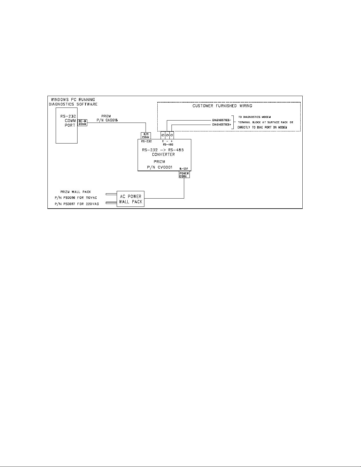
The user is required to communicate with the modems of the system via RS-485. A typical installations
is shown in the following drawing. This details a diagnostic connection through a RS-485 submux
channel.
Page 12 of 13
Page 13
Moog Components Group 4 Port 10/100/1000 Mbps Ethernet Switch February 23, 2009
(201640-xxx)
Figure 1- Typical Cabling/Wiring for Back plane Diagnostics Telemetry
Page 13 of 13
 Loading...