

Page 1
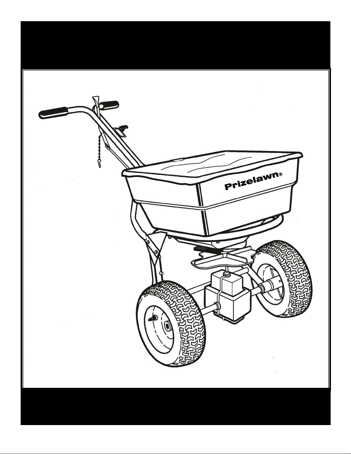
Prizelawn® BF l HVO
COMMERCIAL BROADCAST SPREADER
MODEL
BF l HVO
OWNER’S MANUAL
Page 2
ASSEMBLY
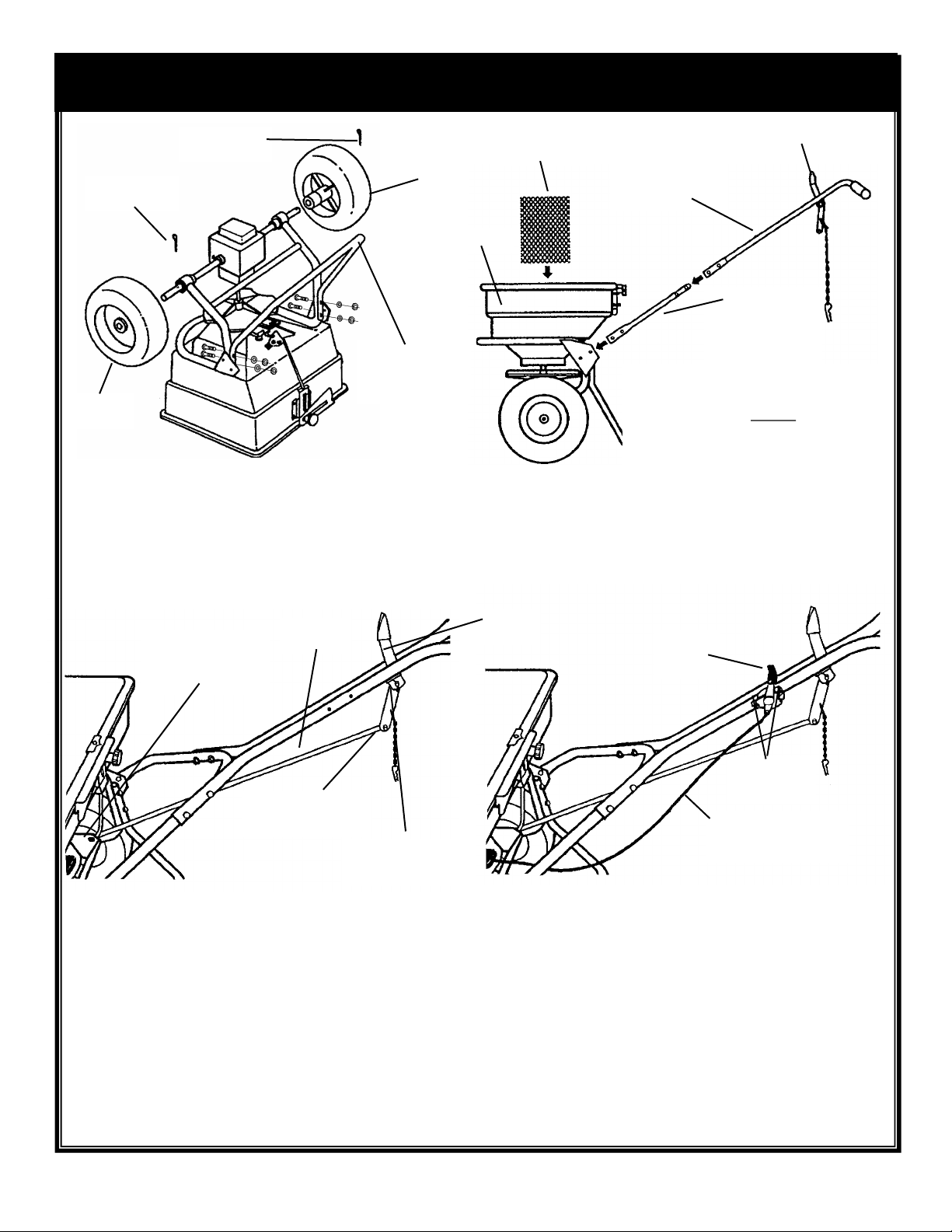
5/32 Dia. x 1 1/4”
COTTER PIN
FREE
3/16 Dia. x 2”
COTTER PIN
DRIVE
WHEEL
Attach to frame with
(4) 1/4-20 x 2 1/4” hex
bolts, lockwashers,
WHEEL
LEG
and nuts
1. Remove spreader and components from carton
and place spreader upside down. Slide drive and
free wheels on axle as shown with the longer
portion of wheel hub facing the frame. Secure free wheel with
a 5/32 Dia. x 1 1/4” cotter pin. Secure drive wheel to axle with
3/16” Dia. x 2” cotter pin. Attach leg to frame using (4) 1/4-20 x
2 1/4” hex bolts, lockwashers, and nuts.
ON/OFF LEVER
LOWER HANDLE
BRACE
nuts
HOPPER
SCREEN
Insert into hopper
UPPER HANDLE
ASSEMBLY
Attach to brace with
(4) 1/4-20 x 1 1/2” hex
bolts, lockwashers,
and nuts
Attach to frame with
(4) 1/4-20 x 5/8” hex
bolts, lockwashers, and
2. Turn spreader upright on wheels and
insert screen into hopper. Attach lower
handle brace to the outside of frame with
(4) 1/4-20 x 5/8” hex bolts, lockwashers,
and hex nuts. Do not tighten bolts. Attach
upper handle assembly to brace
(make sure on/off lever is positioned as shown) using (4) 1/4-20
x 1 1/2” hex bolts, lockwashers, and nuts. Tighten securely.
Install handle grips onto upper handle.
CONTROL
Opposite end of Control
Tube slides onto lower
rod and is secured w/
3/32 Dia. cotter pin
Control Tube attached
with 1/4 Dia. clevis pin
and 3/32 Dia. cotter pin
TUBE
Handle Lever– attach
with 1/4 Dia. clevis pin
and 3/32 Dia. cotter pin
3. Slide handle lever between lever brackets as shown and
secure with 1/4 Dia. clevis pin and 3/32 Dia. x 5/8” cotter
pin. Install on/off control tube to control lever using 1/4
Dia. clevis pin and 3/32 Dia. x 5/8” cotter pin.Remove
tape holding the lower rod to the pivotlever and slide
opposite end of control tube onto lower control rod.
Secure with a 3/32 Dia. cotter pin. TIGHTEN ALL NUTS
AND BOLTS LEFT LOOSE IN STEP #2.
Handle
Lever
Trim
Control
Lever
#10-24 x 2 1/4”
Screws and
Locknuts
Control Cable secure to lower
brace w/ plastic
cable tie
4. Attach trim control lever to the upper handle using (2)
#10-24 x 2 1/4” screws and locknuts. Secure control cable
to lower brace with the plastic cable tie. TIGHTEN ALL
NUTS AND BOLTS LEFT LOOSE IN STEP #2.
5. To check spreader for complete shutoff, pull the on/off control lever back to the “OFF” position. Determine if the
port holes are completely closed. If they are not, loosen the brace/frame bolts and push down on the handle and front
of spreader. Re-tighten bolts and check shutoff.
Page 3
OPERATION
This spreader is designed to apply normal lawn products or it can be easily converted to apply high volumes
of pelletized mulch, sand, ice melt, limestone, and other FREE FLOWING products.
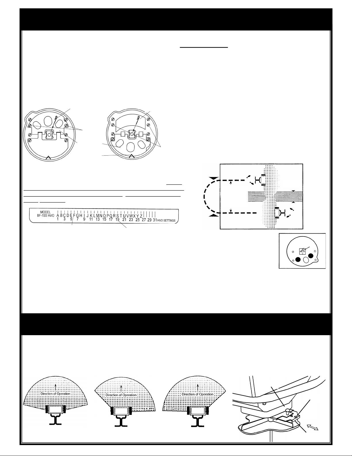
1. This spreader is factory set to apply normal lawn
products. To convert to the HVO mode, slide the agitator
wire out of the impeller shaft and remove the (2) screws
securing the port plate inside the hopper. Flip the port plate
over and lock under the clip in the hopper as shown.
Reinstall the screws into their original holes and slide the
agitator wire back into the impeller shaft.
Reinstall
Remove Agitator
Wire
Remove
Screws
Flip Port Plate
Over
Hopper Clip
Agitator Wire
Reinstall Screws
Back into Holes
2. Check the product package for the rate setting (letter), pattern
setting, (number), and recommended swath width. Loosen the rate
control knob and slide the rate plate to the proper rate setting. NOTE:
the rate plate scale is split into two sections. The “A thru Z” scale is for
fertilizers and other standard lawn products. The #1 thru #31 scale is
for the HVO mode.
5. The setting and swath width on the product label are
recommended starting points. Always check the delivery rate
and pattern on a small area before treating a large area. Actual
delivery rates can vary due to weather condition, operating
variables, and condition of the products being applied. See
“HOW TO DETERMINE SETTING AND SWATH WIDTH” for
details.
6. For fertilizer and other turf products, push spreader at 2 1/2
m.p.h. (18 feet in 5 seconds). Some HVO products require a
reduced speed to obtain the proper spread pattern and
delivery rate. Apply header strips at each end of area to be
treated then space trips across the area as shown.
7. To keep material off walks, flower beds, borders, etc.,the
pattern can be narrowed by pulling the trim control lever on
the handle to the “ON” position. The pattern will end just
beyond the right wheel.
OVERLAP
Use Swath Width
on Package or
Adjust per
operator’s
Walking Speed
Scale For Fertlizer & Other Lawn Products
3. The trim control is remotely operated at the handle. This adjusts the
pattern on the RH. side. The auxiliary slide is set at the hopper and
adjusts the pattern on the LH. side. The pattern control to center the
pattern from left to right is described below. See “PATTERN
ADJUSTMENT” for further details.
4. Before filling hopper, make sure on/off control lever is in the “OFF”
position. For fertilizer and other lawn products, make sure screen is in
the hopper. For large partical HVO products, remove the screen. Fill
hopper. Start spreader moving before opening ports, close ports before
stopping spreader. Always push spreader. DO NOT PULL. Hold handle
so top of spreader is level.
HVO Scale
8. A narrow band of product can be
applied by closing the trim control
and the auxiliary shut-off slide
leaving only the center port open as
shown.
9.Empty the spreader after each use. Return leftover
material to its original container.
10. When transporting the spreader, make sure the
on/off control lever is locked in the “OFF” position securing
the lever with the hitch pin.
PATTERN ADJUSTMENT
Normal spreading of material requires no adjustment unless otherwise stated on the package. In those cases where
the spread pattern has shifted, the pattern can be adjusted. If the pattern is heavier to the left (as viewed from the
operating position), loosen the knob and move the control plate in toward the hopper. If it is heavy to the right, move
the control plate out away from the hopper. Tighten knob after each adjustment is made. A scale is stamped into the
control plate to provide settings.
Knob
Normal Pattern
Pattern Heavy
Right
Pattern Heavy
Left
Scale
Control Plate
Page 4
HOW TO DETERMINE SPREADER
SETTINGS AND SWATH WIDTH
Two major factors should be considered when determining correct spreader settings of
any product:
1. The product application rate, or the amount of material applied per 1,000 square feet.
2. The effective pattern width, or the actual width in which the material is applied. Label
settings are a guide and can be effected by numerous factors.
EFFECTIVE PATTERN WIDTH
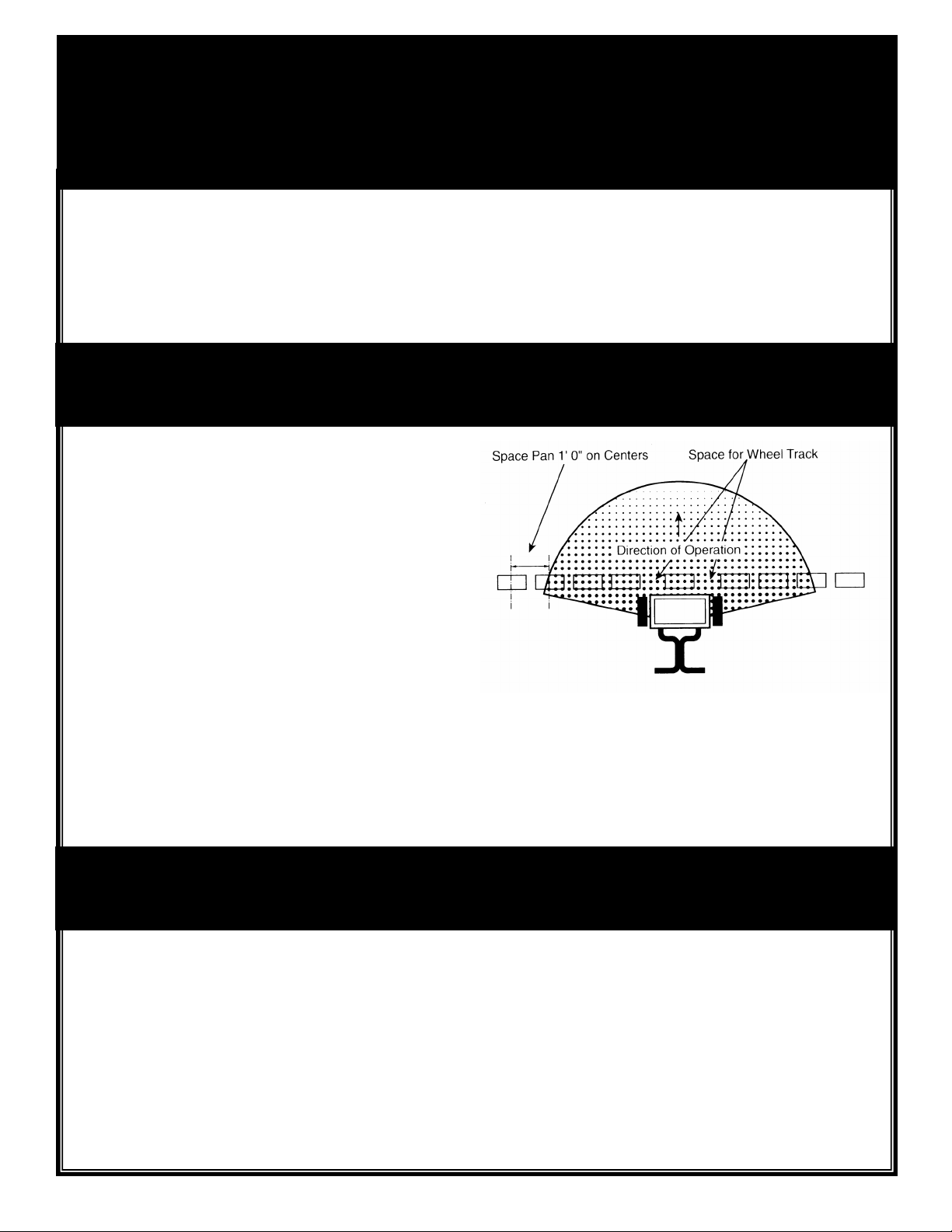
A simple visual pattern test can be made by
operating spreader over a non-turf area and
evaluating the pattern. A more accurate method
is to place a row of common, disposable, aluminun cake pans approximately 1 foot on centers. Set the rate plate at a middle setting and
make 3 or 4 passes in the same direction as
shown. Pour the material collected from each
pan into individual bottles of the same size. Set
them side by side in order, and visually inspect
their volume. If the pattern is not centered
(example: volume in bottle #2 left not equal to
bottle #2 right) adjust the pattern control as
described in the “PATTERN ADJUSTMENT”
section.
Once the pattern is uniform, the effective pattern
width can be determined. the effective pattern
width is the distance out from the spreader to a
point where the amount of material is 1/2 the
average amount in the center pans. This distance is multiplied by 2 to achieve the total
effective pattern width.
APPLICATION RATE
Knowing the effective pattern width (for example, 10
feet), measure a distance equal to 100 square feet (10’
length x 10’ swath width). Determine the product
coverage in pounds-/100 sq. ft. by taking the weight of
product and dividing it by the recommended square
foot coverage (add two zeros to the weight of the bag).
EXAMPLE: Product Weight: 25 lbs.
Sq. ft. Coverage: 5,000 sq. ft.
2,500 lbs. divided by 5,000 sq. ft.
= .5 lbs. / 100 sq. ft.
Weigh out between 15 to 20 lbs. of material and
spread over the 100 sq. ft. area. Weigh remaining
material left in hopper and adjust rate setting as required. Repeat test until application rate is
correct.
Page 5
MAINTENANCE
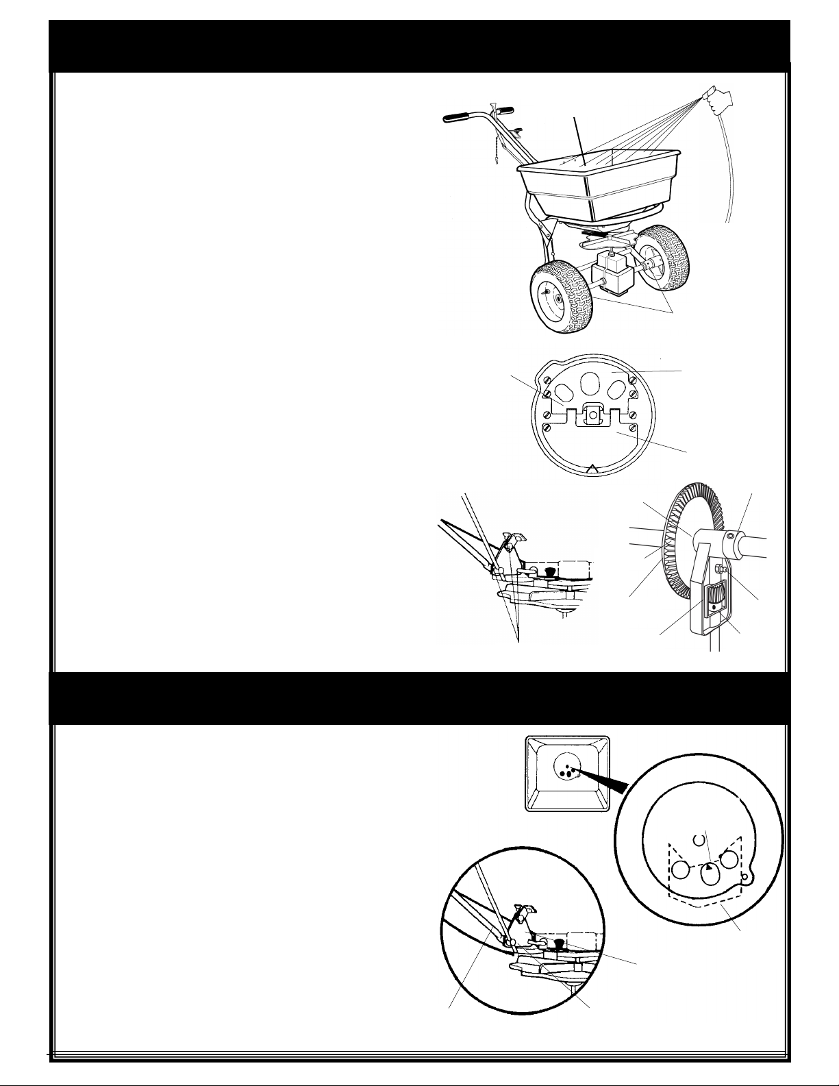
1. Never store material in spreader. Return unused product to
its original container.
2. Wash spreader thoroughly after each use. Make sure the port
and pivot plate inside the hopper are clear of particles that could
prevent the port plate from being flipped over easily. Allow spreader
to dry completely in the sun or heated area.
3. Grease the axle bearings in the frame. Oil the impeller shaft
bearing in hopper, and pivot points on the shut-off linkage and
spring in the housing behind the rate plate.
Oil Bearing in
Hopper
Grease
4. Remove gear cover and clean gears thoroughly.
Apply grease at fitting and gear teeth. Oil all other bearing areas
as shown. Re-install gear cover.
5. Gear mesh should be checked on a regular basis during
high use periods. Clearance between the axle gear and pinion
gear should be minimal, but not tight. If adjustment is
necessary, loosen the axle collar set screw and hold the gears
together. Slide axle collar against the gear support and tighten
axle collar set screw. Spin drive wheel. Gears should run freely
and smoothly.
6. Impeller surface should be cleaned periodically to remove
build-up of product. Build-up can cause the spread pattern to
change.
7. Tire pressure should be 20-25 lbs.
CALIBRATION INSTRUCTIONS
Wash Area
Thoroughly
Oil
Oil
Grease
Axle Gear
Pinion
Gear
Port Plate
Pivot Plate
Axle Collar
Grease
Oil
1. The BFl HVO spreader was factory calibrated, however
calibration should be checked occasionally to assure optimum
performance.
2. Make sure the spreader is in the fertilizer mode (three hole port).
Pull the on/off lever to the closed position.Loosen the rate control
knob and set the rate control plate to setting “A”. Retighten knob.
3. Flip on/off control lever forward to the “ON” position. Check the
center port hole. It should be just open as shown. If adjustment is
necessary, continue to step #3.
Remove cotter pin from the adjusting swivel and slide off control
tube. Slide swivel out of hole in pivot bracket. NOTE SIDE OF
PIVOT BRACKET FROM WHICH IT WAS REMOVED. Thread
swivel up or down on lower rod as required. Install swivel back
into pivot bracket facing the same way it was removed. Check
calibration and repeat unit it is correct. Reinstall control tube and
secure with cotter pin.
Control
Tube
Adjusting
Swivel
Pivot
Bracket
Port Just
Opening
Shut-Off
Plate
Page 6
RATE SETTING CONVERSION
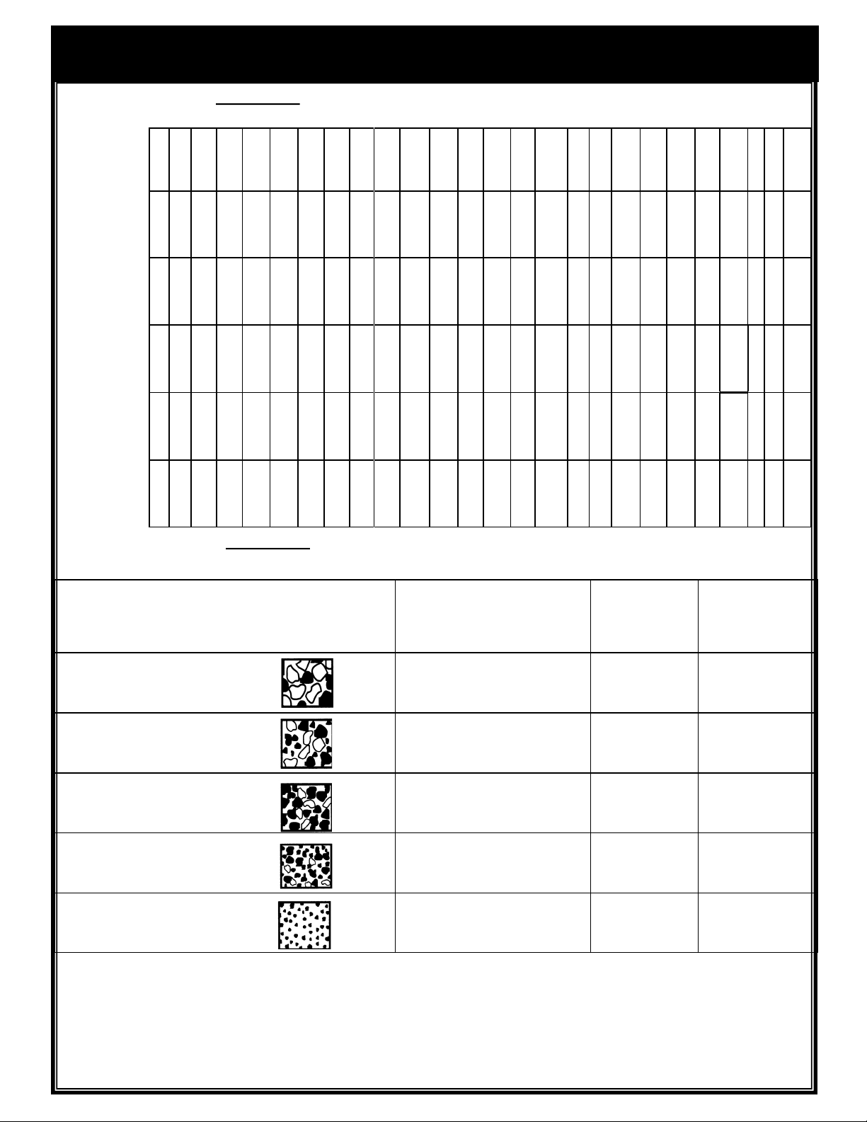
The following provides approximate Prizelawn BF l SS HVO, BF l, and CBR III settings for those units
listed.
Prizelawn
BF l HVO
Setting
PrizeLAWN
BF1/CBRIII
Setting
Lesco
#029600
Setting
Scotts
R8A/SR-1
Setting
Earthway
2200/2400
Setting
Spyker
76/78-2
Setting
The following provides approximate Prizelawn BF l SS HVO, settings when only the product weight,
square foot coverage, and visual inspection of material is available.
A B C D E F G H I J K L M N O P Q R S T U V W X Y
A B C D E F G H I J K L M N O P Q R S T U V W X Y
A — B C D — E F — G H I —
C D E F G H I J K L M N O P
5 — — — —
10 — — — — 15 — — — — 20 — — — — 25 —
— —
— —
3
—
—
4
—
—
5
—
6
K L — M N O — P Q R —
J
R S T U — V
—
Q
—
—
7
—
8
— —
W
—
—
—
9
X Y
— —
30
—
10
—
Z
Z
S
Z
FERTILIZER
PARTICLE SIZE
Large, heavy
particles
Medium- mixed
particles
Small particles
(nitrogen)
Mixed size particles
-some fines
Light weight
particles
The conversions should be used as guidelines for establishing proper rate settings for the particular product
being applied. Steps for obtaining the most accurate settings are outlined in the “How to Determine Spreader
Settings and Spread Width” section of this manual. These settings are approximate and may vary due to
physical characteristics of the product. Walking speed. wear, condition of the turf and humidity, may cause
actual rate setting to deviate. No expressed nor implied warranty or guarantee is provided as to coverage or
uniformity indicated by these rate settings.
BAG RATE
Pounds of fertilizer used
per 1,000 sq. ft. of
coverage
5
10
15
5
10
15
1
2
3
5
10
15
5
10
15
APPROX.
SETTING
J
K
L
G
H
I
D
F
J
I
J
K
F
G
H
SPREAD
WIDTH
(IN FEET)
12
12
12
10
10
10
10
10
10
8
8
8
6
To
8
Page 7
PARTS LIST MODEL BF I HVO
23
24
37
48
44
42
47
46
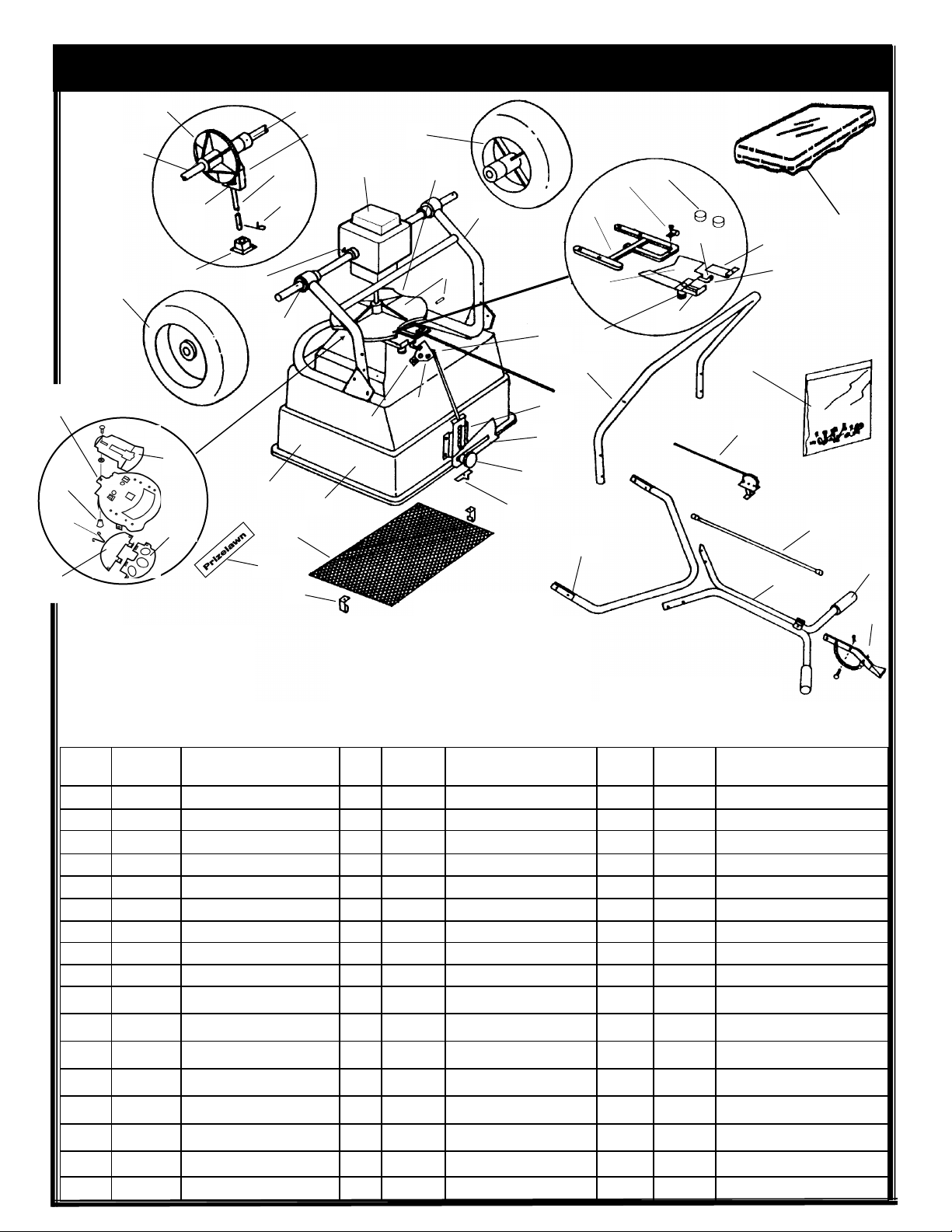
PART OF OUR SERVICE IS PROVIDING REPLACEMENT PARTS,
Parts may be obtained through your
local distributor. Be sure to give the:
1. SPREADER MODEL NUMBER
2. SPREADER NAME
3. PART NUMBER
4. NAME OF PART AS SHOWN
10
45
21
27
50
25
22
20
17
29
1
15
16
26
5
1A
IF YOUR LOCAL DISTRIBUTOR CANNOT
38
18
28
19
3
14
SUPPLY PARTS, CONTACT:
13
11
43
12
30
31
7
40
42
2
9
49
35
33
34
41
4
8
6
39
36
32
Prizelawn®
c/o Earthway Products, Inc.
1009 Maple Street / PO Box 547
Bristol, IN 46507
Ph: 800-294-0671 / Fax: 574-848-4249
www.prizelawnspreaders.com
*Parts in hopper ass’y
**Parts in impeller ass’y
*** Parts in shut-off plate ass’y
1
1A
2
3
4
5
6
7
8
9
10
11
12
13
14
15
16
NO.
BF I
HVO
15095 Hopper*
15094 Hopper Assembly
14879 Hopper Hole Plug (2)*
15096-1 Pivot Lever Assembly*
14846 Shut-Off Plate Link*
14848 Reinforcing Plate*
15098 Shut-Off Plate Assembly*
14836-1 Shut-Off Plate Guide*
15100 Aux. Shut-Off Plate-LH.
15107 Bracket W/ Clamp
14312-1 Impeller Bearing Ass’y*
15101 Rate Control Plate*
14885-1 Spring Housing Assembly*
12704 Rate Knob w/ Washer*
12708 Pointer W/ Screw & Nut*
14863 Hopper Screen
14864 Screen Clip (2)
DESCRIPTION NO.
BF I
HVO
17
14865 Agitator
18
15102 Impeller Assembly
19
15071 Impeller w/ Roll Pin**
20
14867-3 Impeller Shaft**
21
14833 Pinion Gear w/ Roll Pin**
22
14834 Gear Support**
23
14832 Axle Gear w/ Roll Pin**
24
14860 Axle
25
14971 Axle Collar (3)
26
14837 Gear Cover (2)
27
14868 Gear Cover Clamps (3)
28
14898 Frame Ass’y. w/ Bearings
29
14855 Axle Bearings (4)
30
14904 Leg w/ Tube Caps
31
14905 Lower Handle Brace
32
14907 Upper Handle
33
14870 Handle Grips
DESCRIPTION
34
35
36
37
38
39
40
41
42
43
44
45
46
47
48
49
50
NO.
BF I
HVO
14047 Handle Lever Assembly
14916 Control Tube
14859 On/Off Control w/ Clamp
14856 Drive Wheel w/ Cotter Pin
14857 Free Wheel w/ Cotter Pin
15426 Fastener Package
15089 Shut-Off Plate***
15099 Aux. Shut-Off Plate-RH***
14001 Knob w/ Carriage Bolt***
14913 Adjusting Swivel
15090 Deflector Plate*
15091 Port Plate*
15092 Pivot Plate*
15105 Port Plate Retainer Spring*
15093 Hopper Bottom Plate*
14827-1 Hopper Cover
16465 Hopper Label
DESCRIPTION
Page 8
OPTIONAL ACCESSORIES
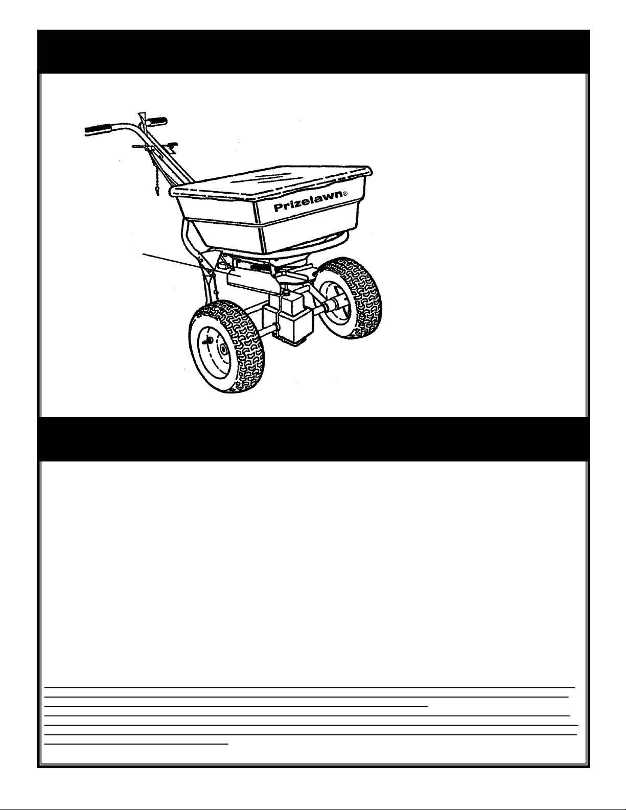
#14889--Side Deflector Kit
Side Deflector
WARRANTY
Prizelawn warrants to Purchaser the following:
1. Product will be free of defects in materials and workmanship for a period of one year from date of purchase.
2. PRIZELAWN will decide in its reasonable discretion if the part(s)/unit is defective.
3. The spreader or part(s) will be shipped to PRIZELAWN at the customer expense with a written description of defect to the attention of
PRIZELAWN WARRANTY DEPARTMENT.
4. If the spreader is used for commercial rental the Limited Warranty shall be limited to a period of 90 days.
5. All Unit and part replacement will be performed at the reasonable discretion of PRIZELAWN.
6. Labor charges are not covered and the unit need not be returned to the dealer for warranty service.
7. Proof of purchase must be supplied to PRIZELAWN.
PRIZELAWN's sole obligation under this warranty is limited to repairing or replacing the defective part. Upon replacement of any Product or Product
part, the replaced item shall become the property of PRIZELAWN. If PRIZELAWN determines that the Product covered by this warranty requires
service, PRIZELAWN shall prepay return shipping charges from PRIZELAWN. In all other instances, such charges shall be paid by Purchaser.
Except for loss or damage caused by PRIZELAWN's negligence, Purchaser relieves PRIZELAWN of responsibility for all risks of loss or damage to
the Product and its parts during the period the products are in transit to and from PRIZELAWN.
This warranty does not extend to any Product or parts thereof that have been allowed to corrode, subjected to misuse, neglect, accident, or
modification by anyone other than PRIZELAWN or that have been affixed to any nonstandard accessory attachment or that have been used, stored,
installed, maintained or operated in violation of PRIZELAWN’s instructions or standard industry practice. No agent, employee or representative of
PRIZELAWN has any authority to bind PRIZELAWN to any affirmation, representation or warranty concerning the Product and any affirmation,
representation or warranty made by any agent, employee or representative shall not be enforceable by Purchaser.
THIS WARRANTY EXTENDS ONLY TO THE ORIGINAL PURCHASER AND IS EXPRESSLY IN LIEU OF ANY OTHER EXPRESS OR IMPLIED
WARRANTIES, INCLUDING WITHOUT LIMITATION ANY IMPLIED WARRANTY OR MERCHANTABILITY OR FITNESS OR INTENDED USE
For A PARTICULAR PURPOSE AND OF ANY OTHER OBLIGATION ON THE PART OF PRIZELAWN.
PRIZELAWN SHALL NOT BE LIABLE FOR ANY INCIDENTAL, SPECIAL OR CONSEQUENTIAL LOSS, DAMAGE OR EXPENSE DIRECTLY
OR INDIRECTLY ARISING FROM THE USE OF ANY OF THE PRODUCT INCLUDING, BUT NOT LIMITED TO, DAMAGE OR LOSS OF OTHER
PROPERTY OR EQUIPMENT, LOSS OF PROFITS OR REVENUE, COST OF CAPITAL, COST OF PURCHASED OR REPLACEMENT GOODS,
OR CLAIMS OF CUSTOMERS OF PURCHASER.
© 2015 Earthway Products, Inc.
 Loading...