

Page 1
1111
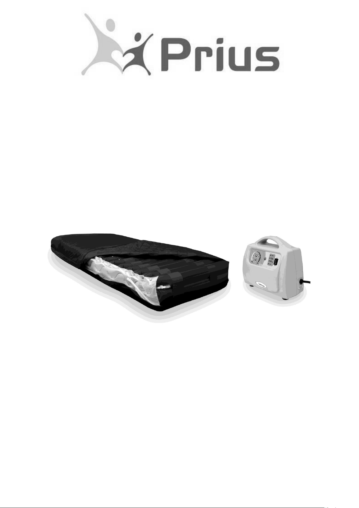
Enhance DX
Mattress Replacement System
User Manual
Prius Healthcare USA
580 Corporate Center
4025 Tampa Road, #1117
Oldsmar, FL 34677, USA
TEL: (813)854-5464
FAX: (813)854-5442
Page 2

Page 3

1
Content
1. THE PURPOSE OF THIS MANUAL.................................................................... 1
2. PRODUCT DESCRIPTION .................................................................................. 1
Master Control Unit Features
Mattress Features
3. TECHNICAL DATA .............................................................................................. 2
Master Control Unit
Enhance DX Mattress Replacement
Symbol Definition
4. INSTRUCTION FOR PROPER USE .................................................................... 3
5. CLEANING ........................................................................................................... 4
The Mattress
The Master Control Unit
Replace Air Filter
Waste Disposal
6. STORAGE AND CARE ......................................................................................... 6
7. MAINTENANCE AND TROUBLESHOOTING .................................................... 6
8. EMC RELATED NOTIFICATION....................................................................... 7
9. WARRANTY…………………………………………………………………….....…10
Page 4

2
Warning
Connect the Master Control unit to a proper power source.
Keep the pump and mattress away from open flame.
Keep sharp objects away from mattress.
Do not place heating device on or near the mattress system.
Do not use the system in the presence of any flammable gases.
(Such as anesthetic agents)
Caution
*
The Alternating System should always be used in accordance with your
Institutions pressure care guidelines.
*
Re-positioning of the patient is always recommended when using an
alternating pressure air mattress (APAM).
*
The control unit should only be repaired by an authorized technician.
*
Do not drop the control unit.
Do not store the system in direct sunlight or extreme cold conditions
*
Operation Temp: 15-40°C ( 59-104℉) R.H. : 30-75 %
Page 5
1
1. The Purpose of this Manual
This operation manual is mainly focused on the set up, cleaning and routine
maintenance of the Enhance DX Alternating Anti-Decubitus System. We recommend
keeping this manual available to answer questions related to the system.
2. Product Description
This product is intended to help reduce the incidence of pressure ulcers while
optimizing patient comfort.
The Enhance DX is an alternating mattress replacement system used in the prevention
and treatment of pressure ulcers. By using the established principles of alternating
therapy the Enhance DX offers patients a comfortable and relaxing support surface
which can prevent skin breakdown and enhance wound healing.
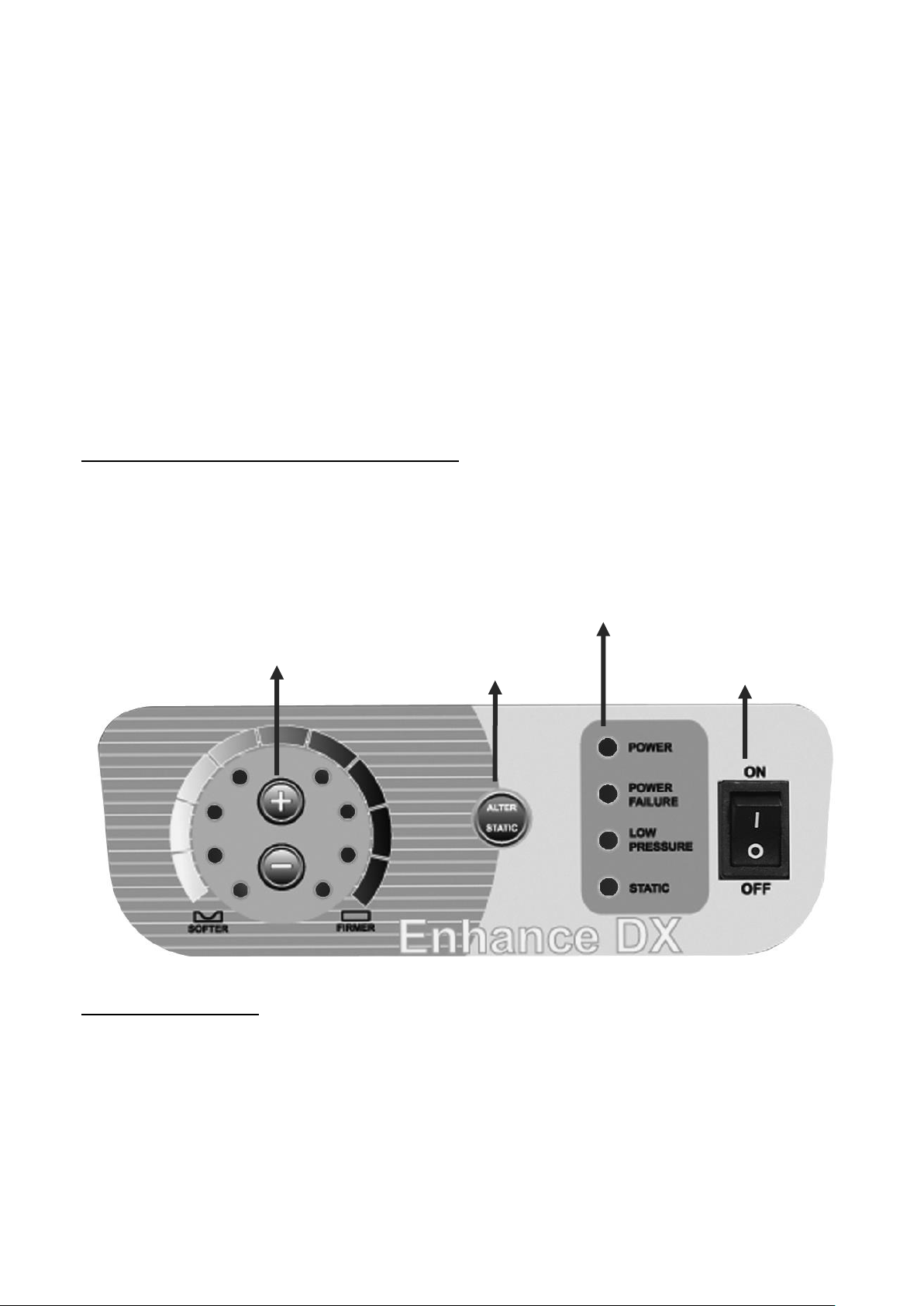
The Enhance DX Control Unit Features
LED indicator for function status.
Electronic adjustable comfort setting.
2-in-1 alternation with 10 minutes cycle time.
Mattress Features
Therapeutic micro low air loss helps manage moisture and provides
alternating therapy to prevent and treat pressure ulcers.
Modularized design for easy air cell replacement.
A vapor permeable, oversized, pliable, quilted nylon top cover provides low
shear, friction and moisture protection.
CPR quick release for rapid deflation.
Integrated power cable management for organization and safety.
Adjustable
Comfort Setting
Alternate/Static
Control Switch
ON/OFF
Switch
Function Status
LED Indication
Page 6
2
3. Technical Data
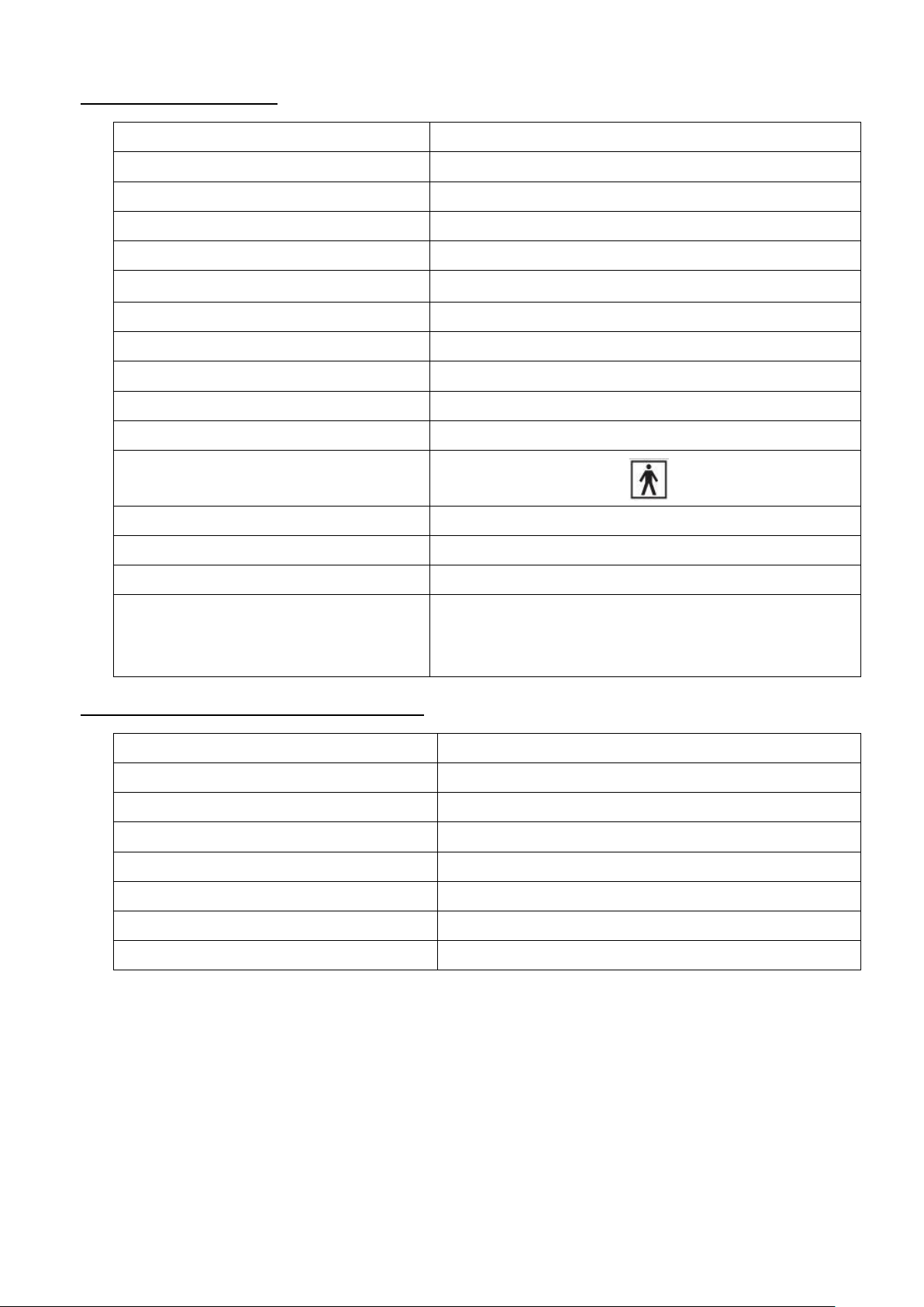
Master Control Unit
Model Name
Enhance DX
Model No.
FC-PHR0004
Size (inch)
10.1” (L) x 4.5” (W) x 8.3” (H)
Weight (lbs)
5.1
Cycle Time
10 min
Min Operating Pressure
12 +/- 5mmHg
Max Operating Pressure
47 +/- 5mmHg
Rated Voltage
AC 110-120V
Rated Frequency
60 Hz
Fuse Rating
1A 250V
Max Current
0.1A
Classification
Class I, Type BF
Not AP or AGP type
Operation Temperature
15°C (59°F)~ 35°C(95°F)
Operation Humidity
30% ~ 75%
Mode of Operation
Continuous
Standard
IEC 60601-1,
CAN/CSA C22.2 No. 601.1,
IEC 60601-1-2
Enhance DX Mattress Replacement
Model No
FM-PHR0004
Size (inch)
36” (W) x 80” (L) x 8” (H)
Weight (lbs.)
21
Cell Number
18cells
Cells Material
Black Nylon with PU coating
Cover Material
Blue Nylon w/ PU coating finish
Base Material
Black Polyester w/ PVC coating
Weight Capacity
500lbs
Page 7
3
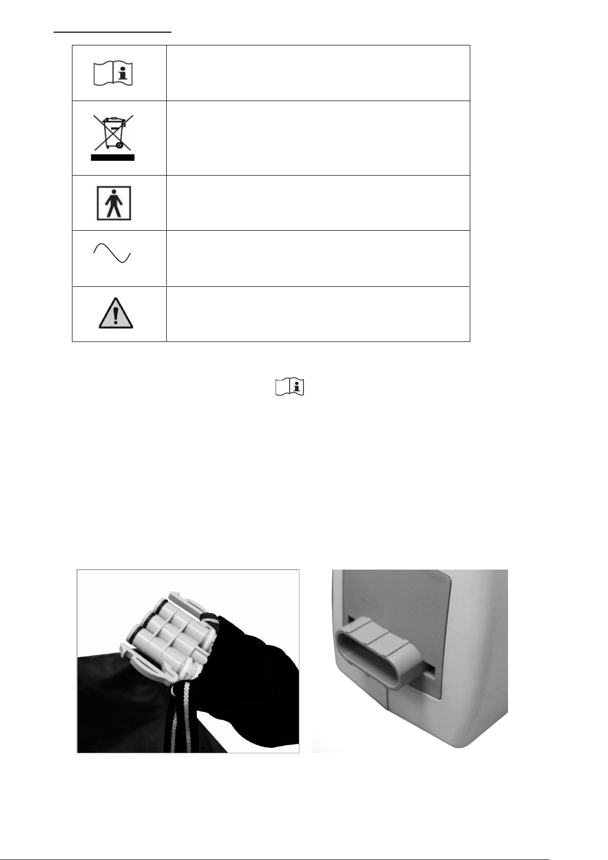
Symbol Definition
Refer to Accompanying Documents
Waste Disposal
Type BF Applied Part
Alternating Current
Caution
4. Instruction for Proper Use
1. Unpack the system and place the pump at the foot end of the bed.
2. Remove the existing mattress from the bed frame.
3. Place the Enhance DX mattress on the frame and position mattress so the air tube is
at the foot of the bed.
4. Secure the Enhance DX mattress straps to the bed frame. .
5. Hang the control unit on the foot board of the bed frame.
6. Connect the mattress air hose to pump.
7. Check air hoses under the mattress to make sure they are not kinked.
8. Plug in the control unit and turn it on.
9. The pump will now inflate the mattress.
Page 8
4
10. Press the control button on pump to select alternation or static therapy.
11. Set the required pressure by pressing the “+” to increase pressure or “-“to reduce
pressure.
12. Pressure is constantly monitored by the control unit. When pressure is less than
the selected pressure the “Low Pressure” LED will illuminate and an alarm will
sound.
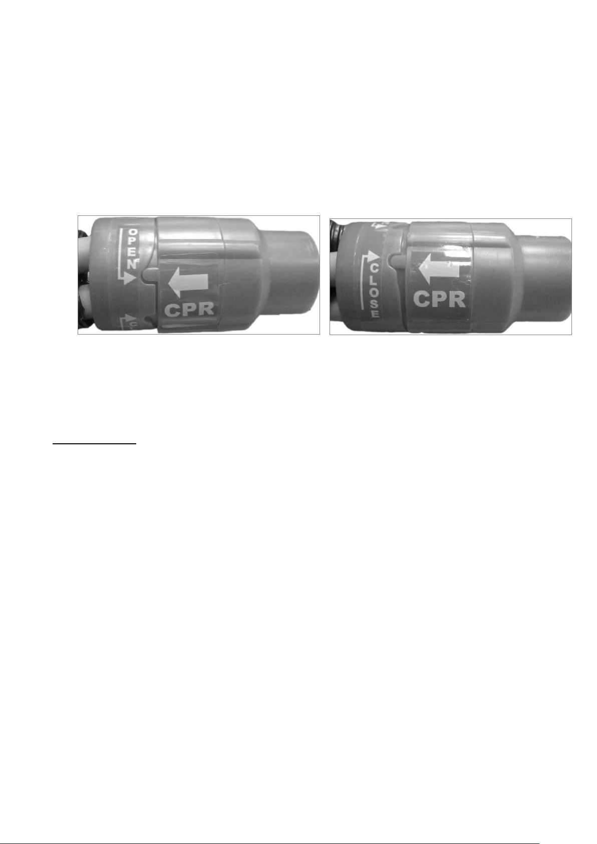
13. For emergency mattress deflation turn the CPR valve to the ‘’OPEN’’ position.
The mattress should deflate within 20 seconds. To close the CPR simply turn the
valve to the ‘’CLOSE’’ position.
Open Close
5. Cleaning
The Mattress
The mattress should be cleaned weekly using a damp soft cloth and mild detergent.
The mattress cover can be washed and thermally disinfected in a washing machine by
following the procedure below. (Do not use a phenol based cleaning solution)
Industrial
Pre-Wash
Cold
10 minutes
Main Wash
60℃(140℉)
6 minutes
Main Wash
70℃(158℉)
10 minutes
Spin Cycle
2 minutes
3 Cold Rinses
Spin Cycle
5 minutes
Domestic
Pre-Wash
Cold
Main Wash
70℃(158℉)
10 minutes
Spin Cycle
2 minutes
Cold Rinses
Spin Cycle
5 minutes
Tumble Drying or Tunnel Drying is not recommended.
Mattress cells can be wiped down with a solution of sodium hypochlorite 1000ppm or
any other non-phenolic germicidal solution.
Page 9
5
The Master Control Unit
The pump unit should also be cleaned weekly using a damp soft cloth and mild
detergent.
The pump casing is manufactured from ABS plastic. If the case is soiled the pump can
be wiped down with a solution of sodium hypochlorite dilution, 1000ppm, or any EPA
approved hospital grade disinfectant. (Do not use a phenol based cleaning solution.)
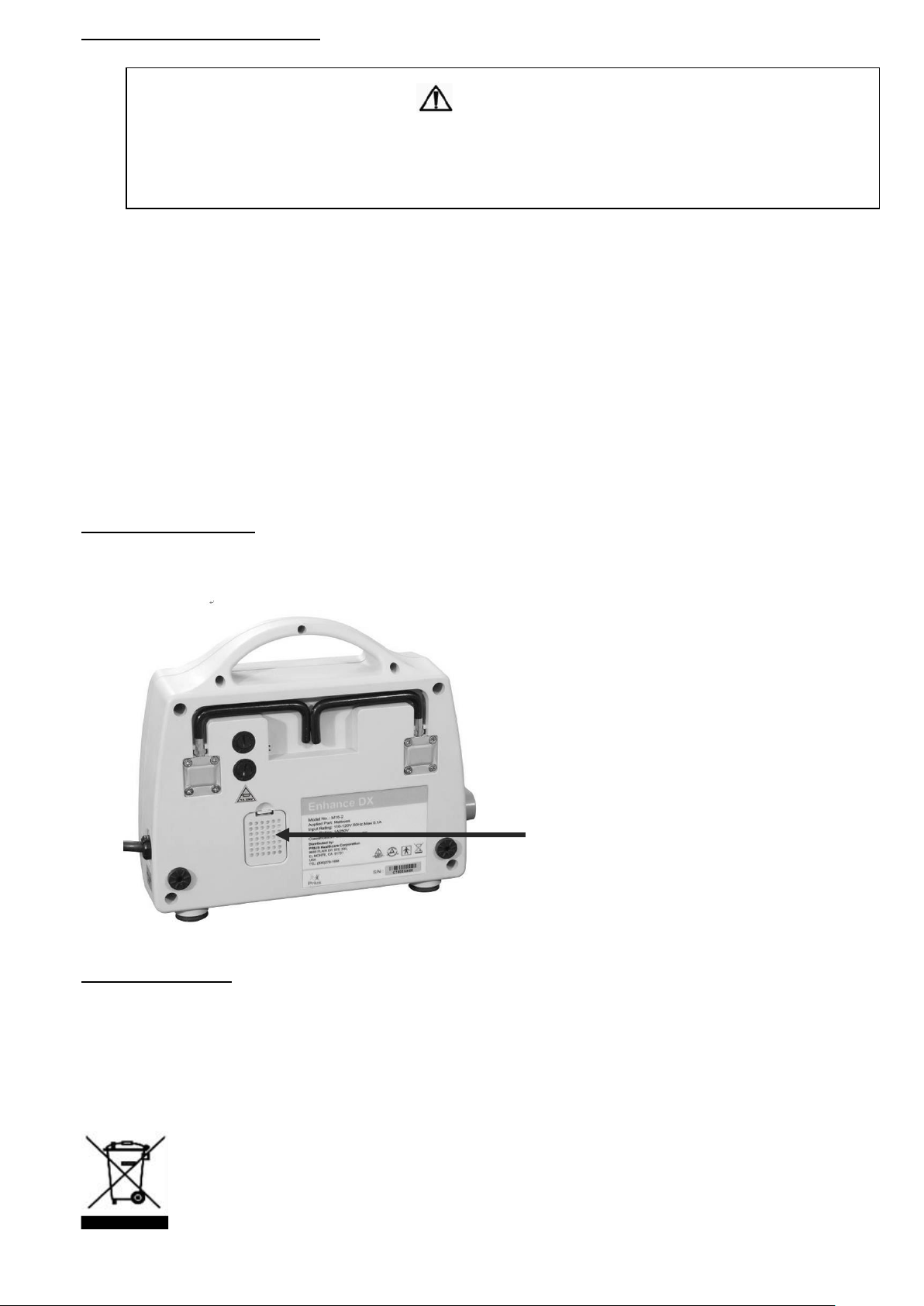
The air filter should also be cleaned and checked at a minimum of every six months.
The air filter can be removed by removing filter cover and pinching center of the
filter and pulling outward from the back of the cover.
Replace Air Filter
1. Remove air filter and replace with a new one.
2. Use a soft bristle to remove dust and difficult dried-on soil.
Waste Disposal
This Product has been supplied by an environmentally conscious manufacturer and
complies with the WEEE.
This product may contain substances that can be harmful to the environment if
disposed of in places that are not approved by your state, local or federal laws. Please
be environmentally responsible and recycle this product through your recycling facility
at its end of life.
CAUTION
SWITCH OFF THE ELECTRICAL SUPPLY TO THE PUMP AND DISCONNECT THE
POWER CORD FROM THE MAIN SUPPLY BEFORE CLEANING AND INSPECTION
Filter
Page 10

6
6. Storage and Care
Master Control Unit:
Check the power cord and plug for abrasions and excessive wear.
Plug in the unit and verify air flow from the hose connection ports.
Place in plastic bag for storage.
Mattress:
Check the air manifold for kinks or breaks and replace if necessary.
Set CPR valve to “OPEN” and disconnect the air hose to the pump. The mattress
will now deflate and can be packed for storage.
It is recommended that the following proceedings are used whenever the system is
being stored or transported to another location:
Temperature limitations: 5°C (41°F) ~ 60°C (140°F)
Relative humidity: 30% ~ 75%
7. Maintenance & Troubleshooting
No daily maintenance is required. This equipment should only be serviced by a
qualified and authorized technician. For common trouble shooting tips please refer
to the chart below.
Symptom
Inspection Procedures
Possible Solution
The pump is not functioning.
1. Check power source
connection.
2. Check fuse.
1. Connect to proper power
source.
2. Replace fuse.
3. Refer to qualified service
technician if problem persist.
Low pressure LED is
constantly illuminated or
the mattress is not inflating
while pump is in operation.
1. Check hoses and hose
connections.
2. Check CPR valve.
3. Check air cells for holes or
tears other than where
designed.
1. Make sure all connections are
secure.
2. Make sure CPR valve is in the
“CLOSE” position.
3. Replace damaged air cell if
necessary.
4. Refer to qualified service
technician if problem persist.
Pump is noisy.
1. Make sure pump is resting
against a solid surface.
1. Reposition the pump.
2. Refer to qualified service
technician if problem persist.
Page 11
7
8. EMC Related Notifications
Guidance and manufacturer’s declaration – electromagnetic emissions
The air pump is intended for use in the electromagnetic environment specified below. The customer or
the user of the air pump is responsible for making sure that it is used in such an environment.
Emissions test
Compliance
Electromagnetic environment – guidance
RF emissions
CISPR 11
Group 1
The air pump uses RF energy only for its internal
function. Therefore, its RF emissions are very low
and are not likely to cause any interference in
nearby electronic equipment.
RF emissions
CISPR 11
Class B
The air pump is suitable for use in all
establishments including domestic and those
directly connected to the public low-voltage power
supply network that supplies buildings used for
domestic purposes.
Harmonic emissions
IEC 61000-3-2
Class A
Voltage fluctuations/
flicker emissions
IEC 61000-3-3
Complies
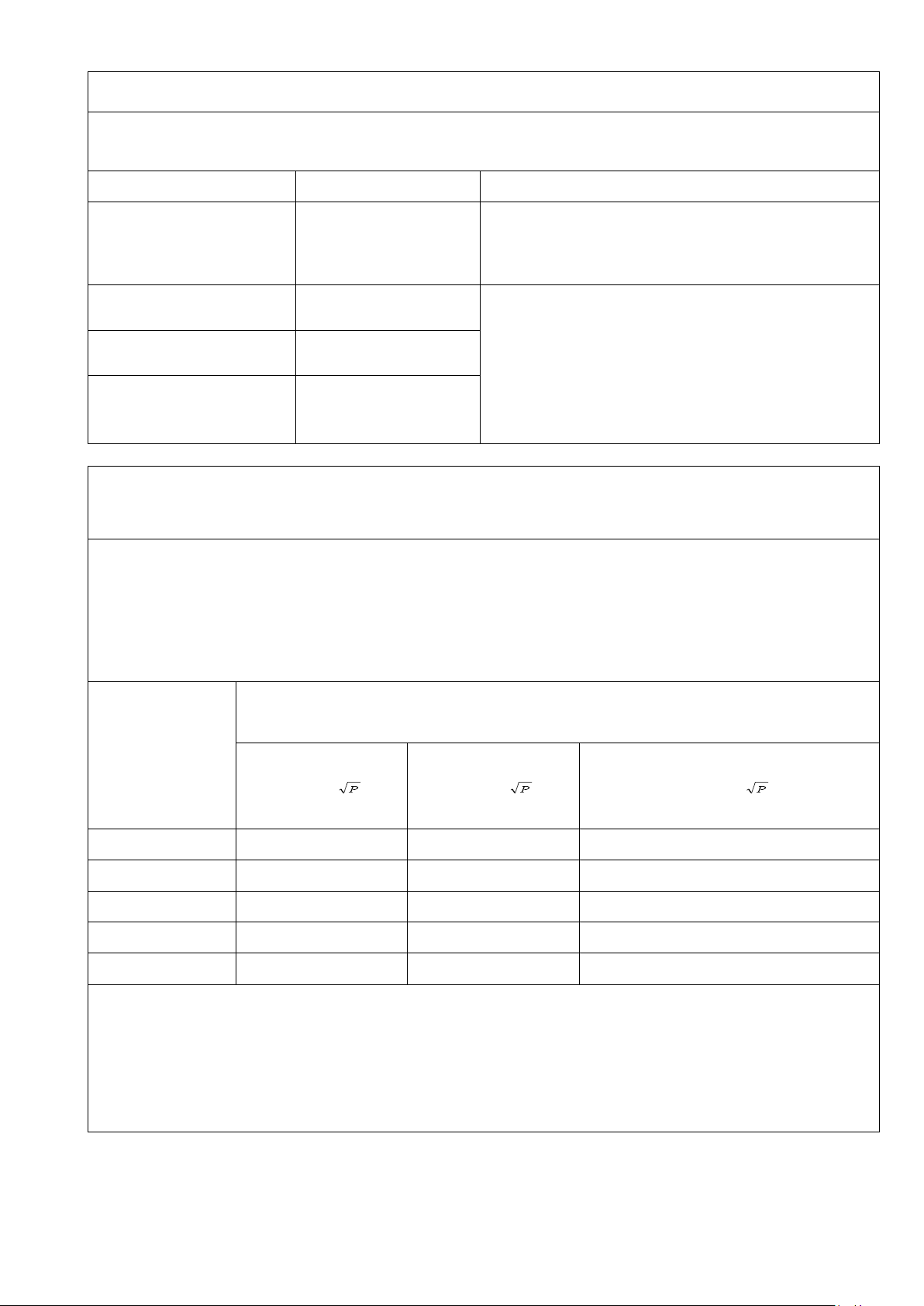
Recommended distances between
portable and mobile RF communications equipment and the air pump
The air pump is intended for use in an electromagnetic environment in which radiated RF disturbances are
controlled. The customer or the user of the air pump can help prevent electromagnetic interference by
maintaining a minimum distance between portable and mobile RF communications equipment
(transmitters) and the air pump as recommended below, according to the maximum output power of the
communications equipment.
Rated maximum
output power of
transmitter
W Separation distance according to frequency of transmitter
m
150 kHz to 80 MHz
d = 1,2
80 MHz to 800 MHz
d = 1,2
800 MHz to 2,5 GHz
d = 2,3
0,01
0,12
0,12
0,23
0,1
0,38
0,38
0,73
1
1,2
1,2
2,3
10
3,8
3,8
7,3
100
12
12
23
For transmitters rated at a maximum output power not listed above, the recommended separation
distance d in metres (m) can be estimated using the equation applicable to the frequency of the
transmitter, where P is the maximum output power rating of the transmitter in watts (W) according to the
transmitter manufacturer.
NOTE 1: At 80 MHz and 800 MHz, the separation distance for the higher frequency range applies.
NOTE 2: These guidelines may not apply in all situations. Electromagnetic propagation is affected by
absorption and reflection from structures, objects and people.
Page 12
8
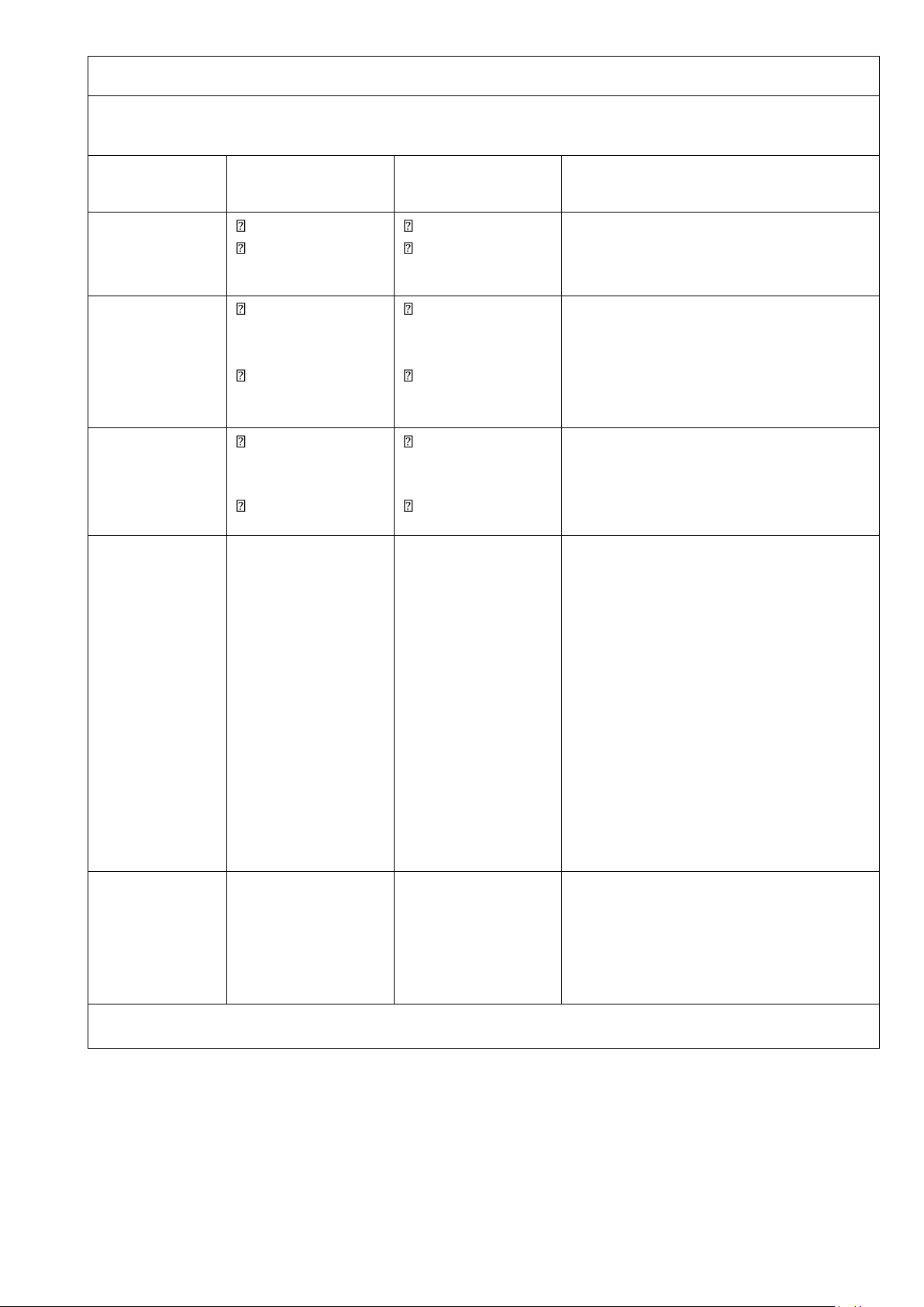
Guidance and manufacturer’s declaration – electromagnetic immunity
The air pump is intended for use in the electromagnetic environment specified below. The customer or
user of the air pump is responsible for making sure it is used in such an environment.
Immunity test
IEC 60601
test level
Compliance level
Electromagnetic environment –
guidance
Electrostatic
discharge (ESD)
IEC 61000-4-2
6 kV contact
8 kV air
6 kV contact
8 kV air
Floors should be wood, concrete or
ceramic tile. If floors are covered with
synthetic material, the relative humidity
should be at least 30 %.
Electrical fast
transient/burst
IEC 61000-4-4
2 kV for power
supply lines
1 kV for
input/output
Lines
2 kV for power
supply lines
1 kV for
input/output
lines
The Main power quality should be that of
a typical commercial or hospital
environment.
Surge
IEC 61000-4-5
1 kV line(s) to
line(s)
2 kV line(s) to
earth
1 kV line(s) to
line(s)
2 kV line(s) to
earth
The Main power quality should be that of
a typical commercial or hospital
environment.
Interruptions
and
voltage
variations
on power supply
input lines
IEC 61000-4-11
<5 % UT
(>95 % dip in UT)
for 0,5 cycle
40 % UT
(60 % dip in UT)
for 5 cycles
70 % UT
(30 % dip in UT)
for 25 cycles
<5 % UT
(>95 % dip in UT)
for 5 sec
<5 % UT
(>95 % dip in UT)
for 0,5 cycle
40 % UT
(60 % dip in UT)
for 5 cycles
70 % UT
(30 % dip in UT)
for 25 cycles
<5 % UT
(>95 % dip in UT)
for 5 sec
The Main power quality should be that of
a typical commercial or hospital
environment. If the user of the air
pump requires continued operation
during power interruptions it is
recommended that the air pump is
powered from an uninterruptible power
supply or a battery.
Power
frequency
(50/60 Hz)
magnetic field
IEC 61000-4-8
3 A/m
3 A/m
Power frequency magnetic fields should
be at levels characteristic of a typical
commercial or hospital environment.
NOTE: UT is the a.c. mains voltage prior to application of the test level.
Page 13
9
Guidance and manufacturer’s declaration – electromagnetic immunity
The air pump is intended for use in the electromagnetic environment specified below. The customer or
the user of the air pump is responsible for making sure it is used in such an environment.
Immunity test
IEC 60601
test level
Compliance
level
Electromagnetic environment – guidance
Conducted RF
IEC 61000-4-6
Radiated RF
IEC 61000-4-3
3 Vrms
150 kHz to 80
MHz
3 V/m
80 MHz to 2,5
GHz
3 Vrms
3 V/m
Portable and mobile RF communications equipment
should be used no closer to any part of the air pump,
including cables, than the recommended separation
distance calculated from the equation applicable to
the frequency of the transmitter.
Recommended separation distance
d = 1,2
d = 1,2 80 MHz to 800 MHz
d = 2,3 800 MHz to 2,5 GHz
where P is the maximum output power rating of the
transmitter in watts (W) according to the transmitter
manufacturer and d is the recommended separation
distance in metres (m).
Field strengths from fixed RF transmitters, as
determined by an electromagnetic site survey, a
should be less than the compliance level in each
frequency range b.
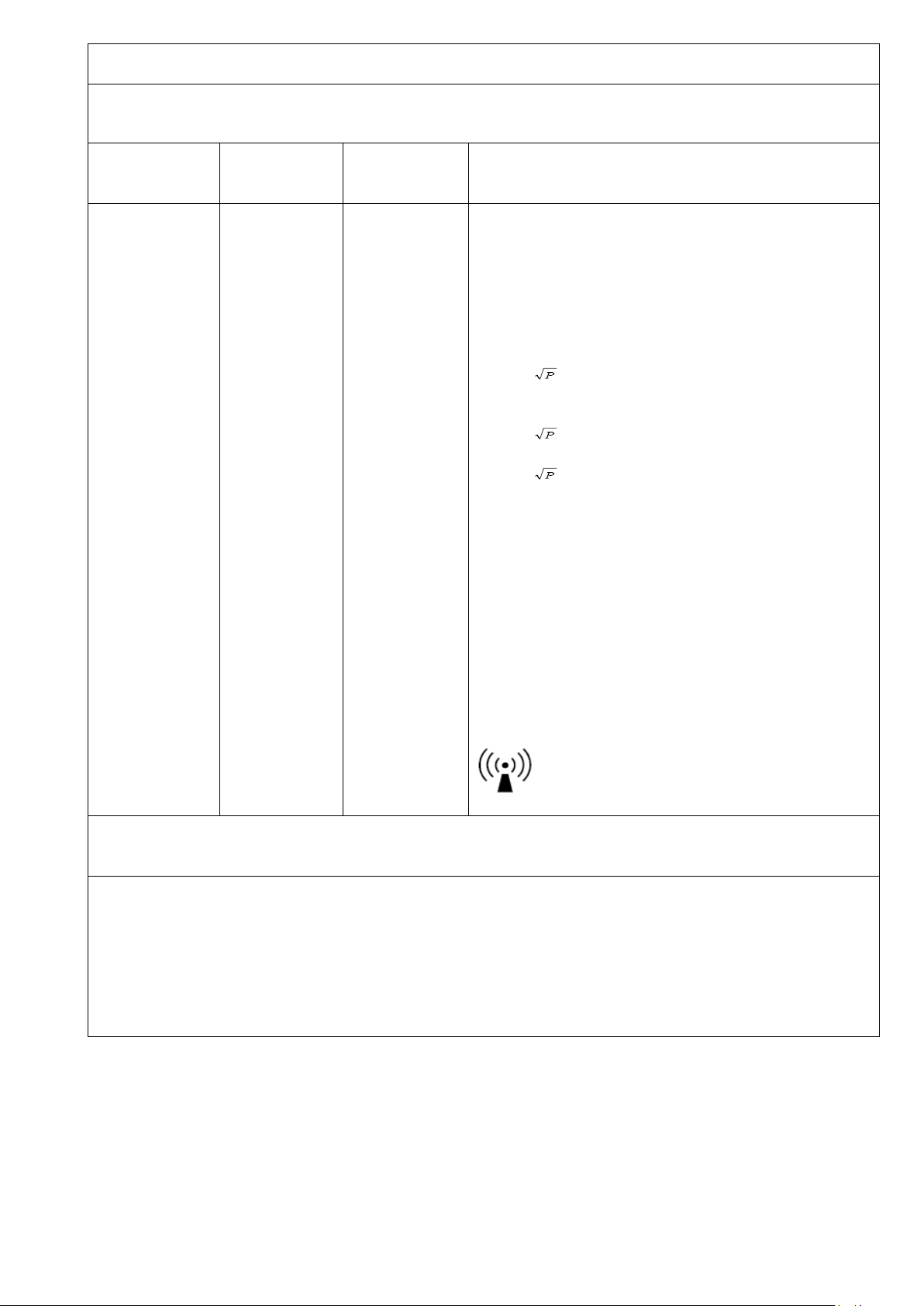
Interference may occur in the vicinity of equipment
marked with the following symbol:
NOTE 1: At 80 MHz and 800 MHz, the higher frequency range applies.
NOTE 2: These guidelines may not apply in all situations. Electromagnetic propagation is affected by
absorption and reflection from structures, objects and people.
a. Field strengths from fixed transmitters, such as base stations for radio (cellular/cordless), telephones,
land mobile radios, amateur radio, AM and FM radio broadcast and TV broadcast cannot be predicted
theoretically with accuracy. To assess the electromagnetic environment due to fixed RF transmitters,
an electromagnetic site survey should be considered. If the measured field strength in the location in
which the air pump is used exceeds the applicable RF compliance level above the air pump should be
observed to verify normal operation. If abnormal performance is observed additional measures may
be necessary such as reorienting or relocating the air pump.
b. Over the frequency range 150 kHz to 80 MHz, field strengths should be less than 3 V/m.
Page 14

10
9. Warranty
Prius Healthcare guarantees this equipment to be free from defects in material and
workmanship for up to 12 months from the date of delivery.
All warranty work will be performed at the service address below, shipping charges
prepaid.
At Manufacturers descreton we agree to service, repair or replace any equipment or
part found to be defective at no charge.
This warranty excludes equipment damaged through shipping, tampering,
improper maintenance, carelessness, accident, negligence, misuse, or which has
been altered, repaired or dismantled other than with the manufacture’s written
authorization and by its approved procedures and by properly qualified
technicians.
In no event shall Prius Healthcare be liable for any direct, indirect or consequential
damage or loss resulting from the use of equipment.
Warranty is non-transferrable.
Page 15

1 AL300099 V1.00
Prius Healthcare USA
580 Corporate Center
4029 Tampa Road, #4000C
Oldsmar, FL 34677, USA
TEL: (813)854-5464
FAX: (813)854-5442
 Loading...