

Page 1
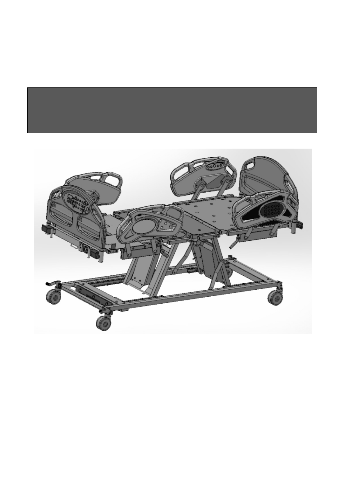
User Manual
Prius – Ai1
'To avoid possible injury during use, read this User Manual in its entirety'
Page 2

Important Precautions
Warning: Possible Injury Or Death. This product is intended for use as an adjustable
mattress support platform with adjustable height for patient and caregiver convenience. Use of this
product in a manner for which it was not designed could potentially result in injury or death.
Warning: Possible Injury. The intended users of this product are healthcare employees and
patients (use of patient controls only) need to be an adult who are at least fifteen years in age and
have the physical strength and cognitive skills to operate the product. Follow facility safety
protocols if an intended user does not have the physical strength or cognitive skills to operate and
control the product safely.
Warning: Possible Injury. Check the area under and near bed perimeter is free of people
and obstructions before operating. Failure to do so could result in injury.
Warning: Possible Injury. Keep bed in lowest position except when providing care (bathing,
clothing changes, etc.). Bed should be at lowest convenient height for entry or exit. Failure to do so
could result in injury.
Warning: Possible Injury Or Death. Floor and caster locks must be locked prior to any
patient transfer or patient use of the bed. Failure to do so could result in injury or death.
Warning: Possible Injury Or Death. Patients with reduced mental acuity should not be
allowed access to pendant for risk of cord entanglement. Unsupervised use of pendant could result
in injury or death.
Warning: Possible Injury Or Death. Bed safe working load is 600 pounds. The safe working
load includes weight counting patient, mattress, bedding and any other equipment. Do not exceed
600-pound safe working load. Exceeding the safe working load could result in property damage,
injury or death.
Warning: Possible Injury. Do not use the product outside the recommended patient height,
width, and weight ranges. The general physical description of an adult is a person who is greater or
equal to 40kg in weight, 146cm in height, and with BMI greater or equal to 17.
Warning: Possible Fire Hazard. Use nasal mask or ½ bed tent oxygen administering
equipment. Oxygen tent should not extend below mattress support platform. Pendant should not be
placed in an oxygen-enriched environment such as an oxygen tent. Use of electrical circuits in an
oxygen-enriched environment could result in a fire hazard.
Warning: Possible Shock Hazard. Always unplug power cords from wall outlet before
Page 3

performing any maintenance, cleaning, or service to the bed. Failure to do so could result in injury
or death. Note: In case of unexpected movement, disconnect battery and unplug bed from any
outlet.
Warning: Possible Shock Hazard. Injury may result from improper routing of the power cord.
Always follow the proper factory-installed routing configuration. Failure to do so could result in
injury or death. Do not position the device where access to mains connection cannot be
disconnected.
Warning: Possible Injury Or Death. Use a mattress that is properly sized to fit mattress bed
deck, which will remain centered on mattress bed deck relative to State and Federal guidelines.
Length and width should match mattress bed deck. Use of an improperly fitted mattress could result
in injury or death.
Warning: Possible Injury Or Death. If a patient’s mental or physical condition could lead to
patient entrapment, the mattress bed deck should be left in the flat and lowest position when
unattended. Failure to do so could result in injury or death.
Warning: Possible Injury or Death. An optimal bed system assessment should be
conducted on each patient by a qualified clinician or medical provider to ensure maximum safety of
the patient. The assessment should be conducted within the context of, and in compliance with, the
state and federal guidelines related to the use of restraints and bed system entrapment guidance,
including the Clinical Guidance for the Assessment and Implementation of Side Rails published by
the Hospital Bed Safety Workgroup of the U.S. Food and Drug Administration. Further information
can be obtained at the following web address:
http://www.fda.gov/MedicalDevices/ProductsandMedicalProcedures/GeneralHospitalDevicesandS
upplies/HospitalBeds/default.htm.
Warning: Possible Injury Or Death. Use a properly sized mattress in order to minimize the
gap between the side of mattress and Side Rails/Assist Devices. This gap must be small enough to
prevent patient from getting his/her head or neck caught in this location. Make sure that raising or
lowering bed, or contouring the mattress support platform, does not create any hazardous gaps.
Excessive gaps may result in injury or death.
Warning: Possible Injury Or Death. Verify all Side Rails/Assist Devices are locked in place
before use. Failure to lock assist devices may result in injury or death.
Warning: Possible Injury Or Death. Do not use any replacement parts not manufactured,
marketed, or provided by Prius Healthcare USA. Use of unapproved replacement parts may result
in injury or death.
Warning: Possible Injury Or Death. If using accessories not manufactured, marketed, or provided
Page 4

by Prius Healthcare USA, consult with the manufacturer for compatibility and limitations prior to use.
Failure to do so may result in injury or death.
Warning: Possible Shock Hazard. Bed power cord has a hospital-grade, 3-prong grounded
plug. Grounding reliability can only be achieved when equipment is connected to an equivalent
receptacle marked “hospital-grade”. If external grounding conductor is in doubt, operate bed from
backup battery. Failure to do so could result in injury.
Warning: Possible Equipment Damage Or Injury To Staff Members. Service and repair
must only be performed by qualified, authorized Prius Healthcare USA.
Warning: Explosion Hazard. Do not use in the presence of flammable anesthetics, gas or
vapors. Failure to heed this warning could result in equipment damage, injury or death.
Caution: Stay clear of underneath the bed when adjusting or moving the bed.
Caution: Mattress bed deck is not grounded, nor does it have a potential equalization
connection point. To prevent injury to patient connected to intravascular or intercardial medical
equipment, alternate measure must be implemented to equalize the potential between mattress
support platform and medical equipment.
Warning: To reduce the risk of injury, ensure the mattress support platform is horizontal and
in the lowest position with the side rails fully raised and locked when moving the bed with a patient
in it. For best maneuverability, push the bed from the head end.
To avoid injury to the patient and/or user, do not attempt to move the bed laterally with the steer
engaged. The wheel cannot swivel.
Warning: The bed should not be used adjacent to, or stacked with, other equipment due to the
risk of electronic interference. If adjacent or stacked use is necessary, the bed should be observed
to verify normal operation in the configuration in which it will be used.
Warning: Using non-approved cables and accessories may negatively affect the EMC
performance.
Warning: Mobile RF communication equipment can affect Medical Electrical Equipment.
Warning: Medical electrical equipment needs special precautions regarding EMC and needs
to be installed and put into service according to the EMC information provided in this manual.
Warning: External equipment intended for connection to signal inputs, signal outputs or other
Page 5

connectors shall comply with the relevant product standard. In addition, all such combinations –
Medical Electrical Systems – shall comply with the safety requirements stated in the general
standard IEC 60601-1. Any equipment not complying with the leakage current requirements in IEC
60601-1 shall be kept outside the patient environment i.e. at least 1.5 m from the patient support or
shall be supplied via a separation transformer to reduce the leakage currents.
Any person who connects external equipment to signal inputs, signal outputs or other connectors
has formed a Medical Electrical System and is therefore responsible for the system to comply with
the requirements. If in doubt, contact qualified medical technician or your local representative.
Caution: Particular precaution must be considered during exposure to strong emission source
such as High Frequency surgical equipment and similar devices. Do not route High Frequency
cables on or near device. If in doubt, contact a qualified technician.
Caution: To avoid damage to the side rail mechanisms, do not move the bed using the side
rails.
Caution: Unplug bed from power source, wrap Power Cord around cord storage hooks on bed
frame below Head Panel and hang Pendant from Head Panel before transporting. Failure to do so
could result in Power Cord, pendant cord, or bed damage, thereby creating a potential hazard.
Caution: Drainage bag loops are not intended for use as tie downs.
This device has no known contraindications.
The Prius Healthcare USA Ai1 Premium bed is intended for use within institutional healthcare
environments 3 (ie: rehabilitation care). Please check your local regulations and guidelines for
compliance.
When assessing the risk for entrapment, you need to consider your bed, mattress, Head/Foot
Panels, Side Rails/ Assist Device and other accessories, as a system. The patient’s physical and
mental condition must be evaluated to initiate an appropriate individual care plan to address
entrapment risk.
Save These Instructions
Page 6

Table of Contents
Bed System Entrapment Information............ 1
Features and Specifications............................ 2
Bed Operation ................................................ 4
Bed Controls.................................................... 5
Manual Bed Controls....................................... 14
Patient Pendant Operation.............................. 18
Additional Features.......................................... 19
Cleaning Procedures....................................... 21
Preventative Maintenance............................... 22
Troubleshooting............................................... 24
EMC Related Notifications……….………….... 26
Expected Service Life...................................... 30
Warranty.......................................................... 30
Page 7
Bed System Entrapment Information
Refer to Accompanying
Although essential in the practice of long-term care, bedside assists, are subject of regulatory
review and evolution in design and use.
The U.S. Food and Drug Administration (FDA) has addressed the potential danger of entrapment
with new safety guidelines for medical beds. These guidelines recommend dimensional limits for
critical gaps and spaces between bed system components.
Entrapment zones involve the relationship of components often directly assembled by the
healthcare facility rather than the manufacturer. Therefore, compliance is the responsibility of the
facility.
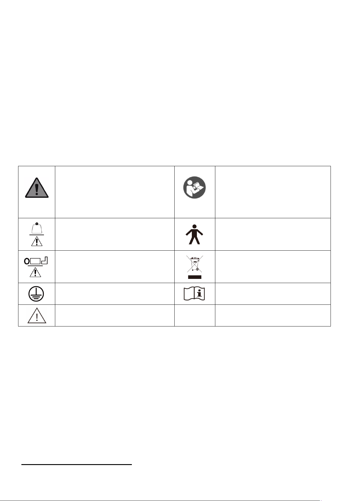
I.D. Label Symbol Definition
Warning
NOTE Background color: yellow
Triangular edge : black
Symbol : black
Safe Working Load
Maximum PATIENT Weight
Protective Earth (ground)
Warning
Refer To Instruction Manual /
Booklet
NOTE Background color: blue
Symbol : white
Type B Applied Parts, user
controls, mattress, support
platform
Waste Disposal
Documents
Features and Specifications
1
Page 8

Standard Features
• Fully adjustable mattress bed deck with independent back and knee movement, up/down
adjustments including AdvancedCare positioning for Trendelenburg and Reverse
Trendelenburg, Auto Contour, Chair and Gravity Assist positioning
• 35" wide mattress support platform sections that can expand to 42” and 48" wide
• Mattress bed deck expands from 80" to 84" and 88" length
• Height adjustable from 10" to 31"
• Side Rails on head and foot sections lower for easy patient access
• Pendant control for all bed functions
• Staff Control with lockouts located in the foot panel and side rails
• Head End Side Rails have back section angle indicators
• Central brake and steer lock
• Emergency manual and electronic CPR release for mattress bed deck
• Emergency battery backup system
• Removable pan-style mattress bed deck for ease of maintenance and cleaning
• Drainage bag loops
• Under bed light
• Integrated USB port
• Integrated IV pole holder (½")
• Integrated pump holder (in the foot panel)
• Safety Stop protection for obstructions
• Auxiliary power outlet on select models
Electrical Specifications
Power: 120 VAC North America
Frequency: 60 Hz North America
Current Rating: 5.0 Amps North America
Classification: Class I, Type B
Mode of Operation: 10% Maximum Duty Cycle, 2 minutes on/18 minutes off
Circuit Protection: Auto Reset Current Sensor
Patient Touch Current Leakage: <100 microamps
Aux. Outlet: 10 Amps
Note: Actuators operate on a 24V DC system
Accessories And Options
• Integrated bed exit alarm
• Integrated patient weigh scale for weight monitoring
• Nurse call integration
• Safety Stop protection for obstructions
• Trapeze/Patient Helper Bar
Environmental Conditions
Operating Conditions:
2
Page 9
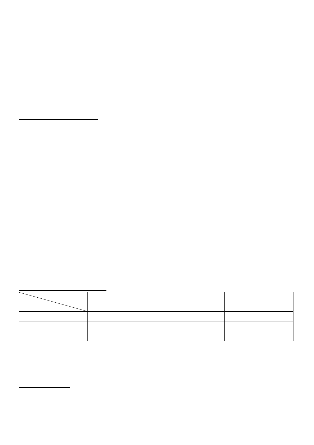
Ambient Temperature: +50°F to +104°F
35 inch
35” x 80”
35” x 84”
35” x 88”
48 inch (2nd exp.)
48” x 80”
48” x 84”
48” x 88”
Relative Humidity: 30% to 75% Non-Condensing
Atmospheric Pressure: 700 hPa to 1060 hPa
Protected Against Splashing Water: IPX4
Storage and Shipping Conditions:
Ambient Temperature: -40°F to +158°F Relative
Humidity: 15% to 93% Non-Condensing
Atmospheric Pressure: 500 hPa to 1060 hPa
Mechanical Specifications
Description: Dimensions:
Model No………………………… Ai1-Premium
Overall Dimensions..................89.7"L x 39.7"W x 10"H
Sleep Surface..........................84"L x 35.0"W x 7.0"H
Weight.............................................................. 466 lbs.
Maximum Back Angle..........................70° to horizontal
Maximum Knee Angle ........................35° to horizontal
Trendelenburg/Reverse Trendelenburg................... 14°
Minimum Height Mattress Support Surface
Base Bed..........................................................10.00"
Maximum Height Mattress Support Surface
Base Bed ...........................................................31.5"
Caster Diameter.........................................................5"
Safe Working Load........................................... 600 lbs.
Maximum Patient Weight.................................. 550 lbs.
Ingress Protection Rating…………………………...IPX4
Expected Service Life……………………………10 years
Recommended Mattress Size
Length
Width
42 inch (1st exp.) 42” x 80” 42” x 84” 42” x 88”
80 inch 84 inch (1st exp.) 88 inch (2nd exp.)
Suggested mattress height: 6”
Bed Operation
Quick Start Set Up
1. Plug bed into electrical wall outlet that is grounded hospital-grade
3
Page 10
2. Place all linens and accessories on bed
3. Zero the bed scale (See scale section)
4. Lower bed to appropriate transfer height
5. Lock casters by engaging the caster brake lever at the foot end
6. Bed is now ready for patient use
Initial Start Up
After positioning bed, always engage caster brake lever.
Warning: It is important to always engage the caster brake lever to prevent unintended bed
movement.
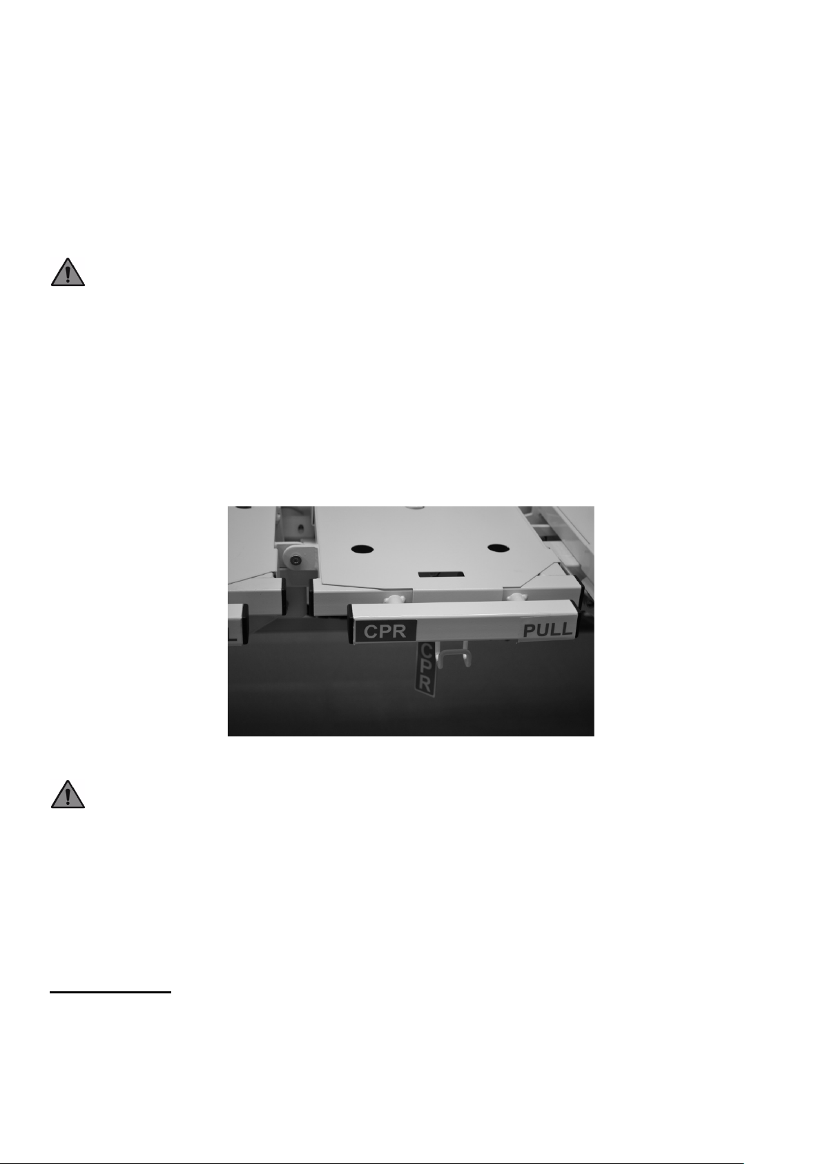
Emergency Manual Mattress Bed Deck Release (CPR Release)
1. The mattress bed deck can quickly be leveled using the pendant or staff control.
2. To return mattress deck to a level position in case of power and battery backup failure, pull the
CPR lever to the side of the bed (Figure 3). Hold CPR handle until mattress bed deck lowers to
desired position. Release handle if you need to stop descent. Note: A total loss of all power will
freeze the movements of all other bed sections and functions. Patient removal is recommended.
Figure 3
Warning: The head section will lower quickly – keep hands clear to avoid injury.
Bed Co
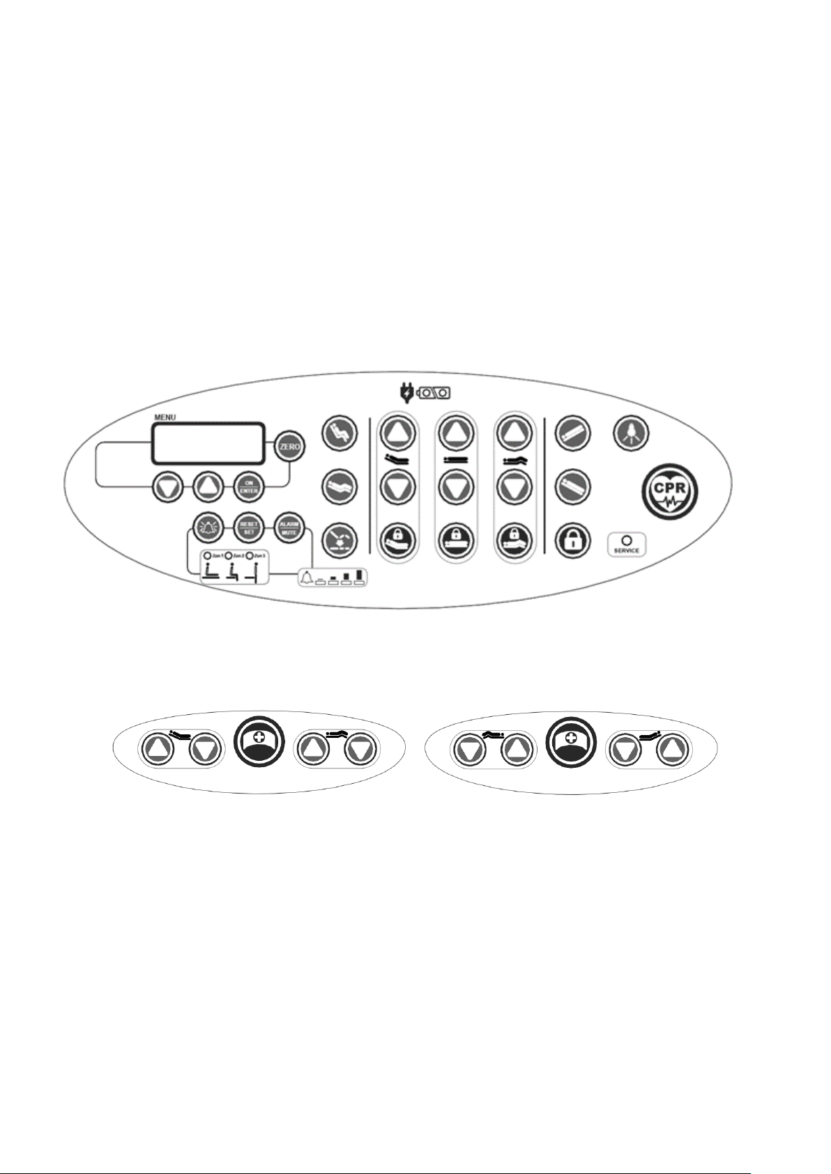
Staff Control Panel Operation
Warning: Possible Injury Or Death. Use Staff Control at the foot panel or in the side rails to
deactivate bed when patient movement or inadvertent activation of bed functions by patient or staff
ntrols
4
Page 11
member could result in personal injury.
The Staff Control panel located at the foot panel and outer head end side rails allows the user to
operate from different points on the bed.
Caregivers can use the control panels to adjust all mattress bed deck sections to desired positions.
The caregiver can also individually lock out all functions on both the Pendant and Staff Control.
1. To lock out a function, press the applicable “Lock” graphic underneath the function. The LED will
illuminate which indicates that function is locked out.
2. To unlock function, press the appropriate “Lock” underneath the function to unlock. The LED is
no longer illuminated, signaling that function is now operable.
Foot panel control (premium version)
Side Rail patient control (premium version)
5
Page 12
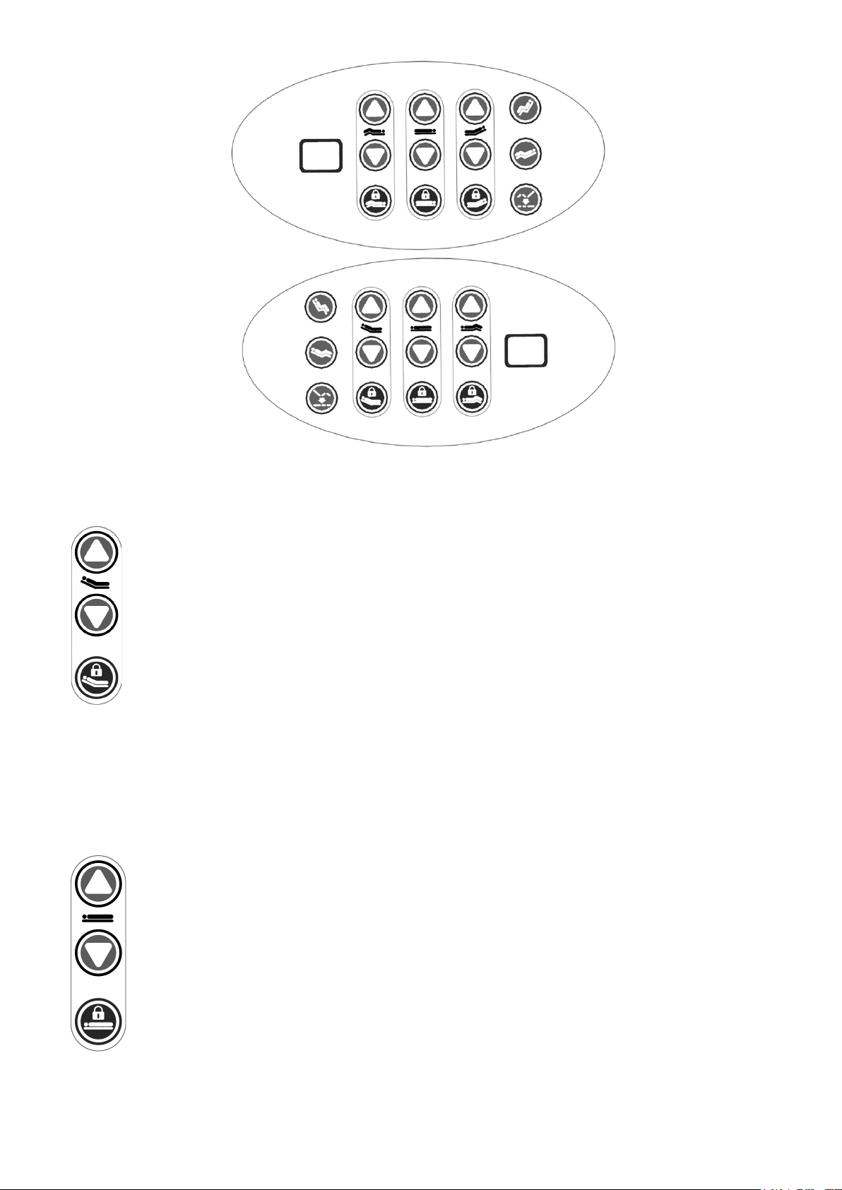
Side Rail Staff Control (premium version)
Head Angle Adjustment
Function: The head angle adjustment buttons allow the head section to move up or
down.
Operation: Press and hold to move the head section to the desired angle. The degree
of head section angle will be displayed in the control panel window located on the head
end caregiver side rails. The angle can be adjusted from 0° to 70°.
Note: When operating the head angle adjustment, the base of the head section slides
progressively towards the head end of the bed. This action stretches the pelvic section of the bed
and helps prevent compression of the abdomen.
Bed Deck Height Adjustment
Function: The bed deck height adjustment buttons allow the bed’s height to be
adjusted
Operation: To move the bed deck up or down, press and hold the appropriate button
on the control panel with the symbol depicted.
6
Page 13

Knee Adjustment
Function: The knee-gatch adjustment buttons allow the knee section to be adjusted
between 0° and 35°.
Operation: To move the knee-gatch section up or down, press and hold the
appropriate button with the symbol as depicted.
Chair
Function: Chair positioning provides synchronized movement of the head section,
knee-gatch section and Reverse Trendelenburg in one operation.
Operation: Press and hold to move the bed into a chair position.
Note: When operating the Comfort Chair button, the base of the head section slides progressively
towards the head end of the bed. This action stretches the pelvic section of the bed and helps
prevent compression of the abdomen.
Contour
Function: Contour positioning provides synchronized movement of the head section and
knee-gatch section in one button operation.
Operation: Press and hold to move the bed into a contour position until the correct
angular position is reached.
AutoTransfer Height
Function: AutoTransfer Height positioning provides synchronized movement of the head
section and knee-gatch section in one button operation to achieve a horizontally level
bed deck at a pre-programmed transfer height of 12”.
Operation: Press and hold to lower both head and knee to a level position and place bed at
transfer height.
Programmable Transfer Height
To Change Pre-Set (Transfer Height ) Height:
Place bed deck at new desired transfer height using the Up or Down buttons - Simultaneously
press and hold ‘Level All’ + ‘Backrest Lock’ buttons for 5 seconds to confirm setting at new height.
7
Page 14
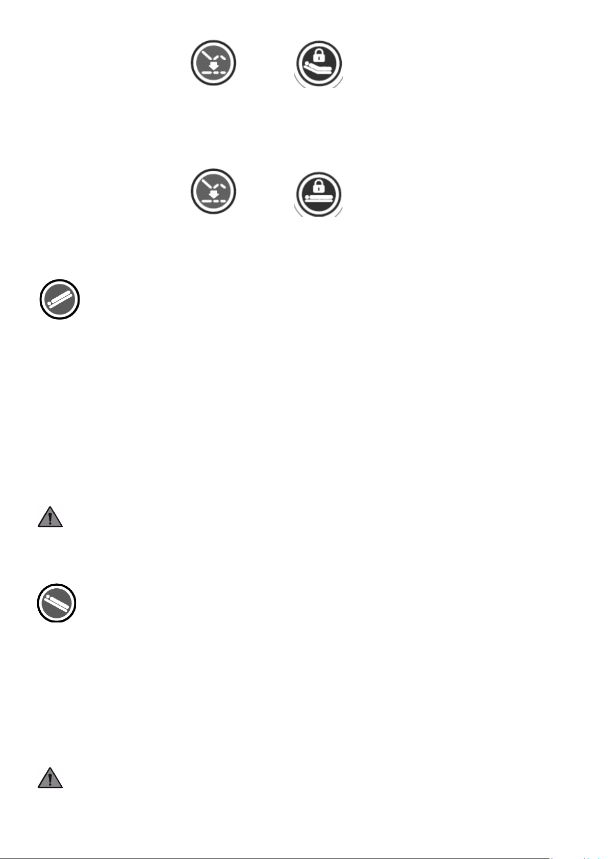
PRESS Simultaneously +
To Change back to Default Pre-Set Height (12”):
Simultaneously Press and Hold ‘Level All’ + ‘Bed Height Lock’ buttons for 5 seconds to re-set the
Default Height back to 12”.
PRESS Simultaneously +
Trendelenburg
Function: The Trendelenburg button allows the bed to be positioned in a head down/foot
up position. Trendelenburg position is achievable between 0° to 14°.
Operation: Press and hold to move the bed deck to the desired angle, digitally displayed briefly in
the control panel window.
Gravity Assist: Gravity Assist limits the head down angle to 4°. The caregiver can select the 4°
Gravity Assist mode for patient safety and positioning. See Gravity Assist section below
Note: To reverse the Trendelenburg angle, press the Reverse Trendelenburg button. When
reversing the bed deck angle (toward Reverse Trendelenburg), it will automatically pause at the 0°
horizontal position. To continue in the same direction, continue to press and hold button to move
bed to the appropriate position.
Caution: The Trendelenburg positions should only be set under clinical advisement.
Reverse Trendelenburg
Function: The Reverse Trendelenburg button allows the bed to be positioned in a foot
down/ head up position. Reverse Trendelenburg position is achievable between 0° and
14°.
Operation: Press and hold to move the bed deck to the desired angle, digitally displayed briefly in
the control panel window.
Note: To reverse the Reverse Trendelenburg angle, press the Trendelenburg button. When
reversing the bed deck angle (toward Trendelenburg), it will automatically pause at the 0°
horizontal position. To continue in the same direction, continue to press and hold the button to
move bed to the appropriate position.
Caution: The Trendelenburg positions should only be set under clinical advisement.
8
Page 15

Gravity Assist Mode
Function: The bed is set to 4° Gravity Assist mode on initial startup. This mode limits the head
down angle to 4°. The caregiver can select the 14° Trendelenburg mode to enable Trendelenburg
functionality.
Operation: Simultaneously, press and hold Trendelenburg and reverse Trendelenburg buttons for
5 seconds on the Staff Control Panel. Trendelenburg/ Reverse Trendelenburg lock icon will begin
flashing indicating that the system is in angle selection mode. For Trendelenburg, press ‘bed up’
button to select full 14° Trendelenburg mode. To return to 4° Gravity Assist, press ‘bed down’
button after following step one.
Under Bed Floor Lighting
Function: Under bed floor lighting provides illumination to the area beneath the bed. The
bed exit alarm will also automatically turn the light on.
Operation: Press and release the appropriate button to turn the light on/off.
Brake
Function: The brake locks casters to prevent bed frame movement.
Operation: Move bed frame into position and step down on the brake pedal located the foot of the
bed until fully engaged. To release, lift pedal up until horizontal to unlock all casters.
Steer
Function: The steer will lock the foot end (identified by yellow cap) caster into straight alignment
for easier bed navigation.
Operation: Lift up on the brake pedal until fully engaged. To release, step down on the pedal until
horizontal to unlock all casters.
CPR
Function: The CPR button lowers the head of bed angle and knee-gatch to flat position,
and then lowers the deck height.
Operation: Press and hold to flatten the head of bed and knee-gatch to horizontal position. Once
the knee and head sections are horizontal the bed deck will lower. If the button is released, the bed
movement will stop. Press and hold the button until the desired position is reached.
Nurse Call Button
Function: The nurse call button sends a signal to the nurse call system when pressed.
9
Page 16
Please note this feature will only communicate when properly connected to a nurse call system.
Operation: Press and release to send a signal to the nurse call system.
Function Lockout
Function: The function lockout button disables one or more bed functions.
.
Operation: Press and release the lock button under the head, Hi/Lo or knee-gatch section buttons
to lockout individual controls. To release the lockout, press and release the same button again. This
function can be enabled or disabled from either the side rail or foot panel control panels. To lockout
all functions, press and hold any adjacent set of two lockout buttons
simultaneously. Repeat to unlock all functions.
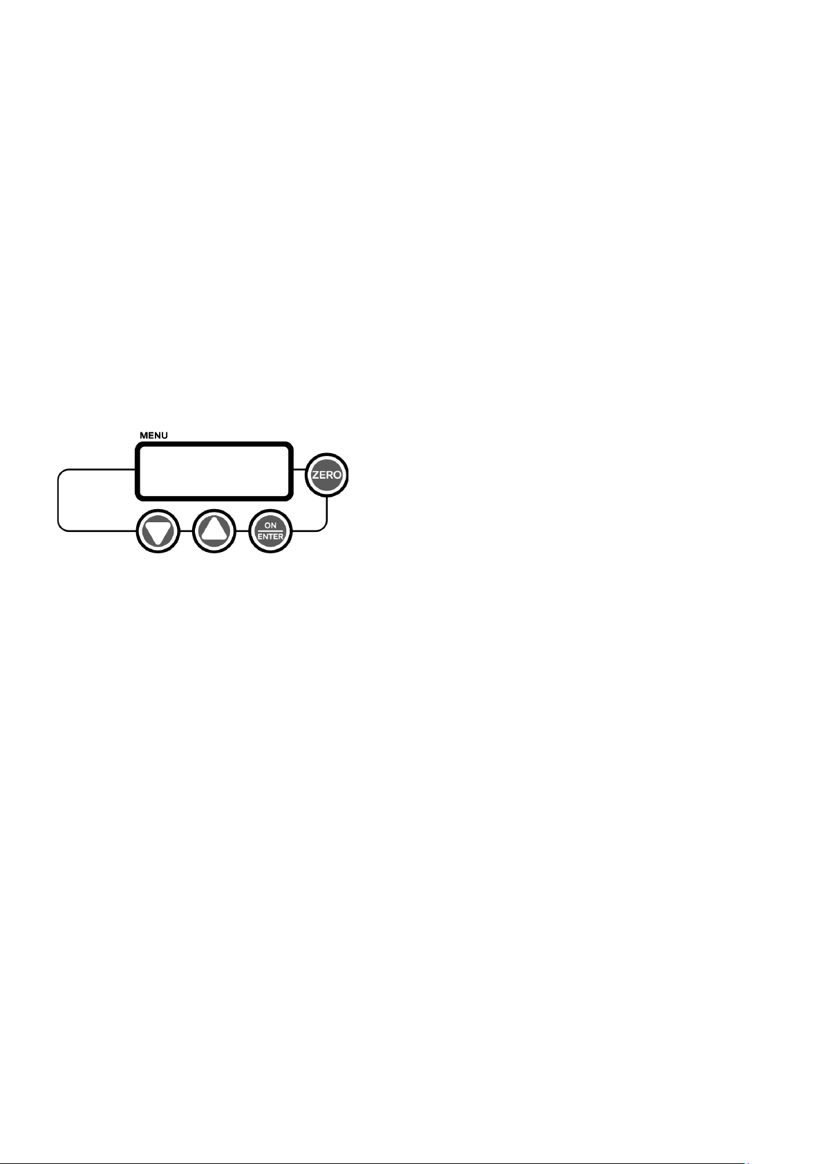
Patient Weigh Scale
The patient scale monitors and records the weight and
weight change of a patient.
10
Page 17
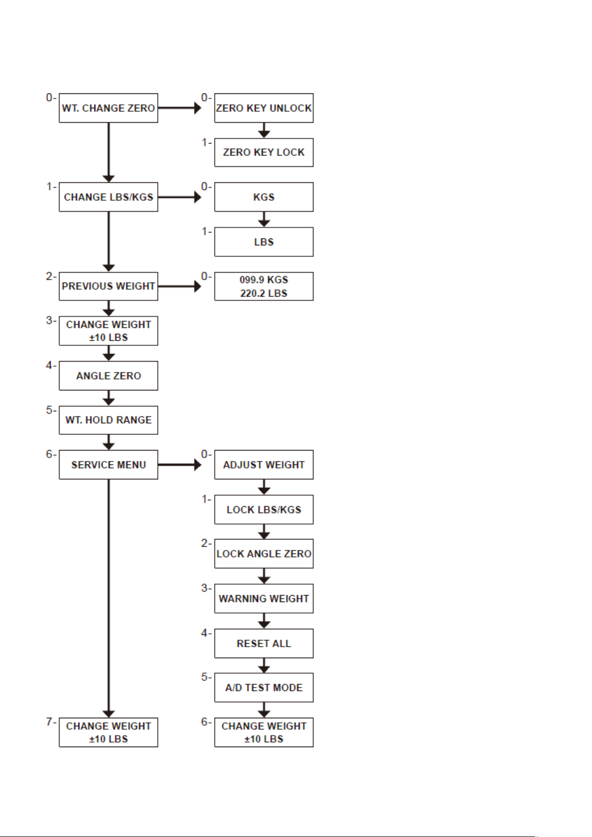
Patient Scale Menu Options
Main menu and sub-levels of the scale system.
Patient Scale Display and Function (New Patient)
11
Page 18
Note: With bed mattress, pillow and linens in-place, perform the following set up prior to placing the
patient on the bed.
1. Press and hold the ZERO button until countdown begins, then release. Display counts down
from 5 to 0 seconds, visually resetting the weight to zero (0.0 lbs). Note: The bed is now ready to
place patient on mattress.
2. Place patient on bed and allow for the displayed weight in the window to remain constant. A
symbol “^” under the displayed weight of the new patient will appear indicating a stabilized value
has been recorded; at this moment, the value will be saved and locked into the scale memory
automatically. The bed exit alarm can now be set.
3. Check patient’s data:
a. Patient’s Weight: Press and release the ON/ ENTER button to display patient weight.
b. Patient’s Weight Change: Press and release ON/ENTER button twice to display options.
Press and release the scale UP and DOWN buttons to scroll through the menu, find
“Change Weight” and the patient’s weight change is displayed.
To exit menu:
Press and release the scale UP and DOWN buttons to scroll through menu. Select “Exit Menu,”
then press and release the ON/ENTER button. Upon exiting the menu, patient’s weight will be
displayed again briefly.
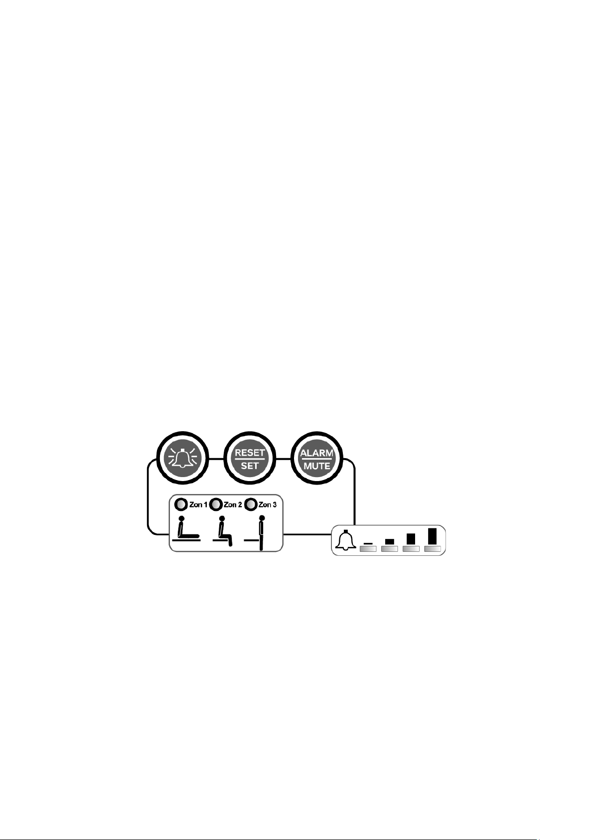
Bed Exit Alarm System
1. With patient in bed, press and release the RESET/ SET button and scroll through the zones to
select the appropriate sensitivity (zone 1, 2 or 3). An indicator light will illuminate next to the
selected zone.
2. Select the appropriate audio volume level by pressing the ALARM button as needed to scroll
through the options (mute, low, med and hi). An indicator light will be seen showing the selected
level is activated, including the mute mode (in this mode the exit alarm will only activate through
the nurse call system if connected).
3. The alarm can be temporary muted by pressing and releasing the ALARM/MUTE button. The
button’s light color will change to green indicating that the audio is off, but the exit alarm remains
active if connected to the nurse call system.
Note: Zone 1 can be disabled:
12
Page 19
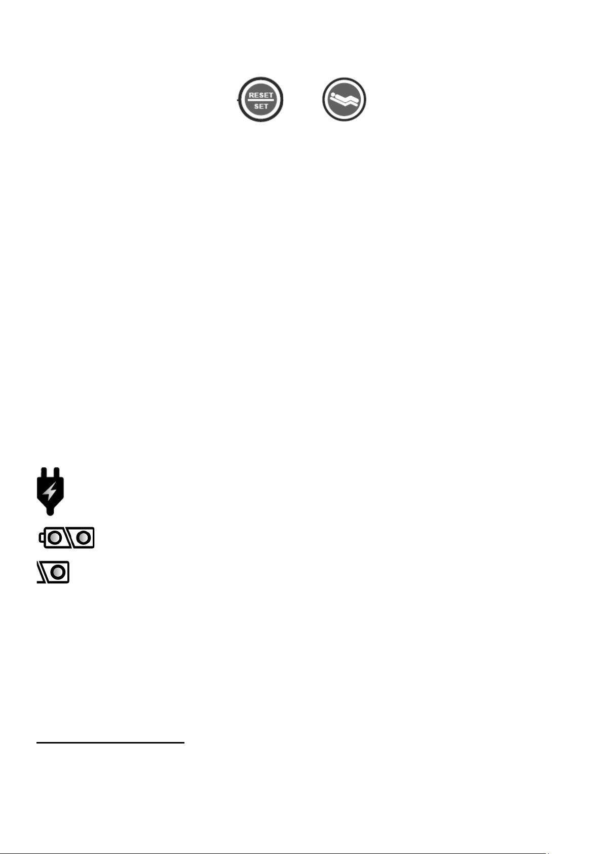
1. Press and hold the Reset/Set button + Contour for 5 seconds to disable/enable Zone 1.
+
a. Zone 1 LED will flash once to signify the zone is disabled
b. Zone 1 LED will flash twice to signify the zone is enabled
2. When Zone 1 is disabled, only Zone 2 + Zone 3 will be available for patient monitoring.
Battery Backup System
The bed is equipped with a battery backup system, which allows the electrically operated functions
to be used when the bed is disconnected from the main power source. The bed transitions between
main power and battery power automatically. To charge the battery, connect the power cord to a
grounded hospital-grade receptacle. The bed should be plugged in as often as possible to
maximize battery life.
If the bed is not used for a long period of time, it is recommended that the battery be charged at
least 24 hours before operating on battery power.
Note: Keep the bed plugged into a main power receptacle for optimum performance and higher
adjustment speeds.
Bed adjustments will be slower when the power cord is unplugged and the bed is powered from its
battery backup system.
Illuminates when plugged in
Illuminates when unplugged and fully charged
Illuminates when battery charge is low
Manual Bed Controls
Side Rails
The standard split side rails have two positions: up and down. When the side rail is raised to its up
13
Page 20
position, it will automatically be locked in place.
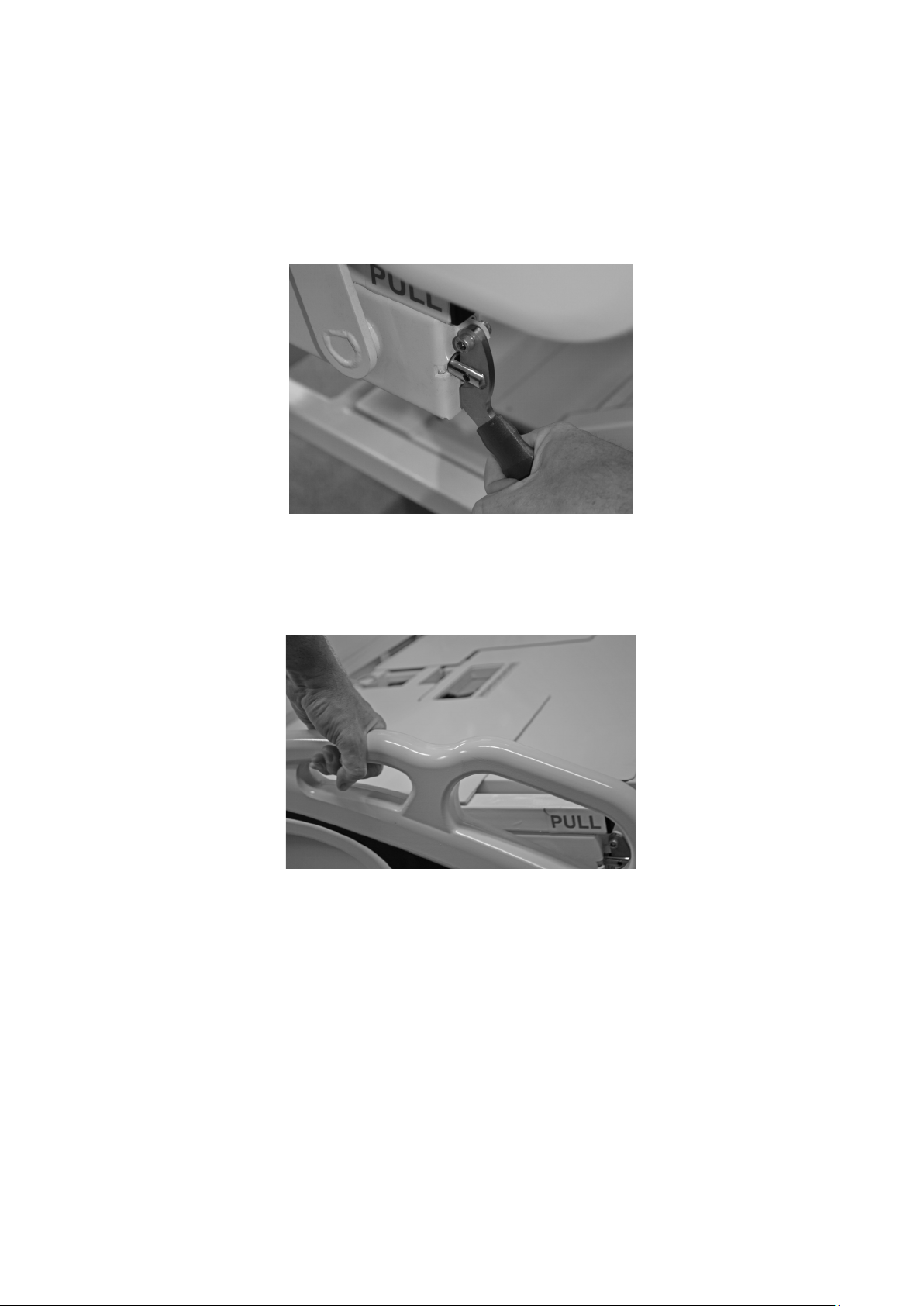
Side Rail Operation
Note: The side rail will only lock in the in the up position.
From the up position to lower position (Figure 4): While holding the upper hand-hold of the side
rail, pull the green lever up to release and lower the side rail (there is no lock in the down position).
Figure 4
From the lower position to the up position (Figure 5): while holding the upper hand-hold of the
side rail, lift the side rail to the up position, the lever will automatically click into its locked position.
Figure 5
Manual Cariopulmonary Resuscitation (CPR) Release Function
The emergency CPR release handles are positioned in the pelvic area on both sides of the bed.
The manual release function returns the bed’s head section to a fully down position in the event of
an emergency resuscitation. To manually lower the head section in an emergency, pull out one of
the red release handles marked “CPR” (Figure 6). If the head section does not go down on its own
push the head section with one hand while still engaging the CPR handle with the other.
14
Page 21
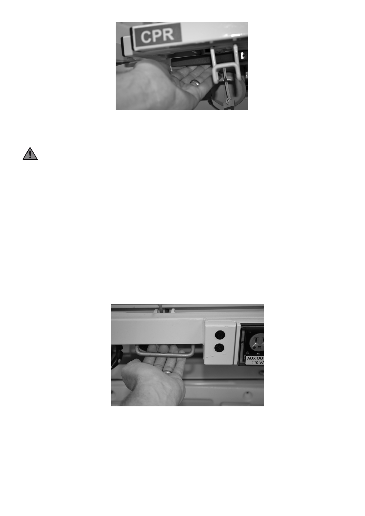
Figure 6
Note: If manual CPR is utilized, the side rail will display the last head of bed angle position. To
reset the display, press and hold the head down button on the caregiver side rail control panel.
Warning: The head section will lower quickly – keep fingers clear to avoid pinching.
Alternatively, the CPR function can be activated electrically from the foot panel control panel. Press
and hold the red CPR button to move the bed into the desired height. If the button is released, the
bed movement will stop. Press and hold the button until the desired position is reached.
Length and Width Expansion (Mattress Bed Deck)
The length of the bed deck is extendable from 80" to 84" and 88". The width of the bed deck is
expandable from 35" to 42" and 48".
To extend length:
1. Pull up on the extension lock at the foot-end of the bed to release lock in current position (lock is
spring loaded so if when released, lock will reengage) (Figure 7).
Figure 7
2. Grab the frame of the foot panel and gently pull out. Extension lock can be released and will
reengage at the pre-designated length of 84". To confirm proper lock engagement, move the
foot panel back and forth. Repeat step for 88" extension. When expanded to 84" & 88",
remember to expand the panel on the foot section to match sleeping deck with bed frame
length.
15
Page 22
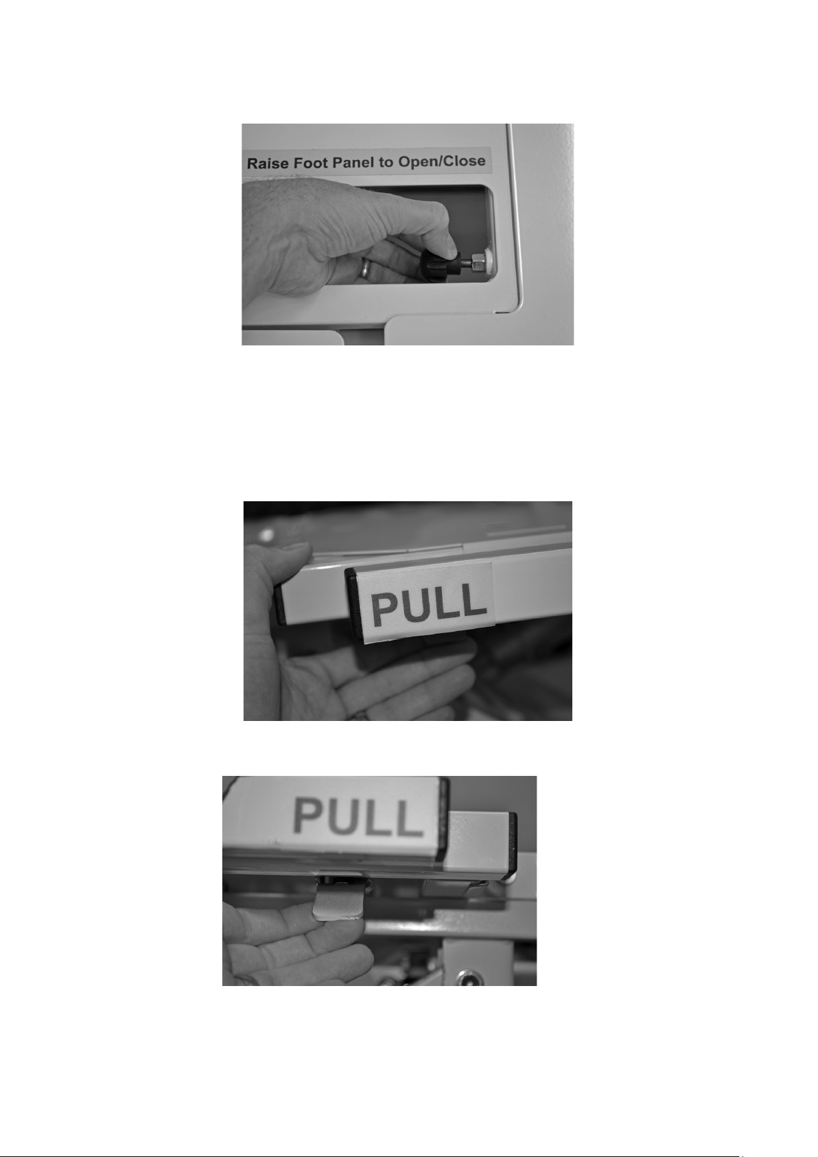
3. The extend the foot panel section pull black knob in the center of the foot section to disengage
lock (Figure 8). Grab the end of the foot section and pull toward foot panel. Release the knob to
lock into place at the pre-designated length of 84" & 88"
Figure 8
Note: Do not extend Bed Frame by grabbing the foot board panel.
To expand width:
The expansion lock for all width extensions is located on underside of the first bar of each deck
section closer to the head end (Figure 9).
Figure 9
1. Push up on the expansion lock to release (lock will reengage when released (Figure 10).
Figure 10
2. With lock released grab the deck extension and pull out. Extension lock can be released and will
reengage at first the slot to achieve 42" length.
3. To ensure the extension is locked, push or pull on the bar. Repeat the above steps on all
16
Page 23
remaining extension sections.
4. Repeat these steps to extend to 48" length if applicable.
Foot Section Leg Lift Adjustment
The foot section angle is adjustable when the knee-gatch section of the mattress support surface is
elevated.
To Elevate Foot Section Horizontally
While grasping the outer edges of the knee-gatch panel close to the footboard (Figure 11), lift
upwards slowly to an elevation angle slightly past the desired position. The foot section has two
ratchet struts that will produce a clicking sound as the spring-loaded locking mechanisms travel
past the range of available locking positions. Once the desired position has been reached, gently
allow the foot panel to lower. The locking mechanism will automatically find the first available
ratchet position.
Figure 11
To Lower Foot Section
While grasping the outer edges of the foot section close to the footboard, lift upwards slowly to
release the spring locking mechanism. Then, slowly lower the foot section until firmly returned to its
original position resting on the main frame.
Patient Pendant Operation
The patient hand pendant allows the patient to adjust the bed frame. Motion occurs only while a
button is pressed and held. Motion will stop when the button is released or the applicable bed
section reaches the end of its range of motion.
17
Page 24
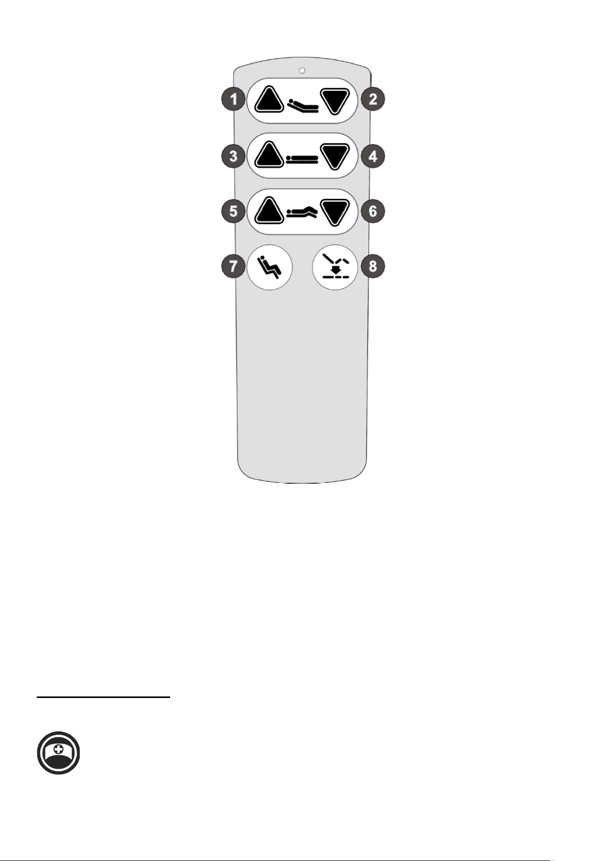
1. Push button to raise head
2. Push button to lower head
3. Push button to raise bed
4. Push button to lower bed
5. Push button to raise knee-gatch
6. Push button to lower knee-gatch
7. Push button for Chair
8. Push button to lower both head and knee to level position and set at transfer height
Additional Features
Nurse Call Connectivity
To connect bed to a nurse call system, a standard 37 pin connection and ¼" jack are
located at the head end of the bed below the mattress support platform (Figure 12). When
connected, bed will send an alarm signal to the nurse call station if nurse call button is
pressed on the patient control panel. In addition, the nurse call station will be signaled if bed exit
18
Page 25
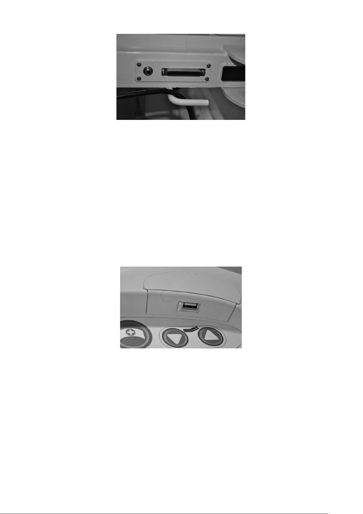
alarm is triggered (See scale section for operation).
Figure 12
Safety Stop System
The weight scale system is designed to detect when the bed frame comes in contact with an object
while lowering. If that occurs, the bed will stop lowering. If the bed is in the process of lowering and
has traveled at least 4” below the highest bed height setting, the bed will stop and raise
approximately 1.5” to free any potential obstruction.
Integrated USB port
Integrated USB ports located on each of the patient side rail controls provide power to USB
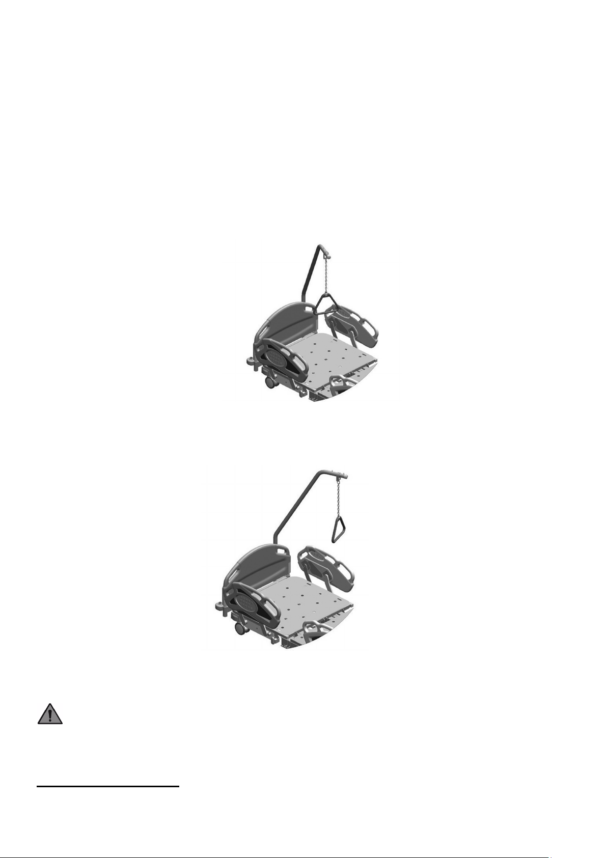
enabled portable electronic devices (Figure 13). To utilize the USB port, slide the port cover to open
position and insert a USB cable into port. Connect cable to electronic device such as a phone or
music player.
Figure 13
Integrated Pump Holder
The foot board panel of the bed features an integrated pump holder designed to easily attach most
air mattress pumps, sequential compression devices (SCDs), and other equipment designed to be
hung on a bed frame.
Auxiliary Power Outlet (Select Models)
The bed is equipped with a 110V hospital grade auxiliary power outlet. The outlet receives power
through a dedicated black power cord. If the auxiliary power outlet is not powering a device, check
that the power cord is plugged into a power source and that the circuit breaker (located next to the
19
Page 26
power outlet) does not need to be replaced.
Optional Trapeze/Patient Helper Accessory
The optional trapeze/patient helper has a limited safe working load (SWL). Refer to Trapeze label
for specific SWL. The trapeze handle height can be adjusted by shortening the handle length. To
shorten the handle length, grasp the handle and position at the desired height, then adjust the strap
to the appropriate length on the patient helper bar.
The trapeze has three handle positions:
1. Centered (Figure 15): Positions the trapeze handle above the patient’s upper torso to provide
assistance during positioning.
Figure 15
2. Off set (Figure 16): Positions the trapeze handle and patient helper bar to the side of the bed for
assistance during egress.
Figure 16
3. Left and Right location: The trapeze bar can be installed on the left or right side per patient
need.
Caution: The Patient Helper Bar is only to assist with repositioning on the mattress or during
egress from the bed. It is not designed to the full weight of the patient.
Cleaning Procedures
20
Page 27

Eye protection must be worn at all times during the cleaning and disinfection process.
Caution: Avoid the use of running water and/or pouring disinfectant liquids during the cleaning
process of the bed frame sections.
Recommended Clinical Disinfection Liquids
1. Quaternary Ammonium Disinfectant
2. Activated Hydrogen Peroxide
3. Sodium Hypochlorite (bleach) 1:10 ratio with water
Note: Specific disinfectants may be required by individual clinical facilities.
Caution: Make sure to follow manufacturers’ instructions when mixing and using cleaning/
disinfecting products for optimal results.
Warning: Prior to the commencement of any disinfection process, make sure the power cord
is disconnected.
Warning: Wear appropriate protective gloves, safety glasses and other personal protective
equipment at all times during the cleaning/disinfection process.
Disinfecting
Use of a microfiber washcloth is recommended during the cleaning and disinfection process. For
the removal of stubborn stains, use a soft bristle brush.
Rinsing
Avoid the use of running water or pressurized spray. Always rinse with a clean microfiber
washcloth.
Caution: Allow for sufficient drying time before any reintroduction of the bed frame into a
clinical environment.
Caution: Always use caution to avoid the potential of cross contamination.
Preventative Maintenance
Inspection and Maintenance
Warning: Disconnect power cord(s) from wall outlet before cleaning.
Warning: Do not use power wash or high pressure cleaner on any bed part.
Warning: Lock casters when cleaning, inspecting or performing any maintenance of the bed.
21
Page 28

Initial Inspection
It’s recommended to perform a routine inspection upon initial receipt of bed to ensure optimal bed
functionality.
Specific Check Points For Inspection
1. Actuator bolts - Check attachment points and hardware for deformity and general wear
2. Mechanism pivot points - Check for wear
3. Castors - Check stem tightness, tire, brake cam and bearing wear
4. Central lock - Check linkage for wear
5. Side Rail - Check for smoothness of operation
6. Head/Foot boards - Check for damage
7. Mattress Deck - Check pivot points for tightness and wear
8. Frame Fatigue - Check for any abnormal distortion and weld cracking
9. Bumpers - Check for ease of rotation and wear
10. Labels - Check that all cautionary labels are legible and in place
11. Handset - Check for cracks and cable damage
12. Power Cable - Check for insulation damage and condition of plug prongs
13. CPR Release - Check for cable adjustment and operation under load (approx. 40 lbs. of sand
bags)
14. Check for general overall bed frame condition and cleanliness.
Twelve (12) Month Preventative Check
In addition to initial Inspection procedures above, the following preventative maintenance
procedures should be carried out annually.
General Checks
1. Examine the bed for obvious signs of damage. All aspects of the equipment should operate as
intended. Check that all nuts, bolts and other fasteners are tight and are not missing.
2. Examine flexible cable and conduits for cuts, cracks, abrasions or other deterioration.
3. Check that the power supply plug is not damaged. If either the power cable or plug is damage
then both the cable and plug must be replaced as a complete assembly.
Central Locking System
1. Apply the brakes and push the bed forwards. If any of the four braking castors rotate the brake is
not fully effective, and should be replaced
2. Check the steer lock castor for correct operation.
Trapeze/Patient Helper
Examine the strap and handle for signs of damage.
22
Page 29

Side Rails
If movement does not occur when
1. Check for function lockout on Staff Controls.
Where side rails are fitted -check:
1. The locking pin mechanism and striker plate arrangement should be checked.
2. Inspect the side rails for general wear and tightness of fittings, including pivot joints and
mounting brackets.
3. Check for rust, structural integrity of welds and pain finish.
Storage
Store in a clean dry area.
Plug bed power cord into grounded hospital-grade electrical outlet. Backup batteries, if equipped,
maintain the longest life if kept charged and are not allowed to fully discharge. Failure to keep bed
plugged in will discharge backup batteries and shorten their life.
Lubrication Servicing
Recommended Lubricants
Lubricant: Super Lube® Multi-Purpose Aerosol.
Grease: Use Super Lube® synthetic grease or equivalent.
Oiling Points
Keep pins and bolts oiled.
Oil hinge points.
Grease Points For Mattress Support Platform
Grease Side and Foot Extensions.
Troubleshooting
Pendant and Staff Control Troubleshooting
Problem Solution
Pendant or Staff button is pushed
2. Function may be at maximum or minimum level.
3. Bed is not plugged into power source and backup
battery has discharged. Plug bed into wall outlet.
4. Check pendant cord for physical damage. If cord is
damaged, discontinue bed usage until cord is replaced.
23
Page 30

If adjustment only partially occurs,
Knee Lockout indicator flashes
1. If bed is in a reverse Trendelenburg or Chair position,
1. Backup battery may be low. Plug bed into power
stops and beeps
source.
2. Check Safe Working Load or for any obstructions near
the bed.
3. If a safety stop occurs while loweing the bed, the may
be an obstruction. Raise bed to check and clear obstruction.
Lower the bed to confirm operation. If problems persist,
contact Prius Healthcare USA.
Bed not responding to staff control 1. Check function lockout status.
2. Check Foot Board connection is fully inserted with
cable secured.
3. Check the bed is plugged into power source and power
unit green light is illuminated.
4. Unplug bed and reset battery for 60 seconds, and plug
it back in.
5. If these steps fail to resolve the problem, call Prius
Healthcare USA.
All lockouts indicators flashing 1. Push and hold Hi-Lo up and down on staff control or
pendant simultaneously until flashing stops (No more then
15 seconds).
2. Unplug bed for 60 seconds and plug back in.
3. If these steps fail to resolve the problem, call Prius
Healthcare USA.
when attempting articulation
level bed deck to enable knee-gatch operation.
2. Lower or raise Hi-Lo fucntion to end of travel.
3. If these steps fail to resolve the problem, call Prius
Healthcare USA.
Problem Possible Cause What to Do
Bed movement with all casters
locked.
Scale System display is blank
1. Braking mechanisms may
be worn on one or more casters.
1. Main power cord may be
1. Remove bed from use and contact Prius
Healthcare USA.
1. Plug in main power cord.
after scale button is pushed.
Scale System gives suspect
readings.
unplugged and battery backup
has become exhausted of
power.
2. Unit is defective.
1. Foot Board cable
connection may have
24
2. Contact Prius Healthcare USA.
1. Check for proper connection.
2. Refer to calibration section of this
Page 31

disconnected.
Manufacturer’s declaration-electromagnetic emissions
The Ai1-Premium is intended for use in the electromagnetic environment (for
manual.
Mattress Bed Deck sections do
not extend.
Mattress Bed Deck sections do
not contour.
2. Weight scale may need
calibration performed.
3. There may be an
obstruction under bed.
1. Latch handles not fully
disengaged.
2. Possible Binding.
1. Pendant or Staff Control
operation.
2. Staff Control function may
be locked out.
3. Bed may be defective or
damaged.
3. Raise bed to ensure no obstruction is
present.
1. While pushing the latch handle, try to
extend the mattress bed deck extension.
Refer to width or length extension section of
this manual.
2. Wider bed deck sections may require
two hands to apply equal pull force. Contact
Prius Healthcare USA.
1. Refer to Pendant or Staff Control
Troubleshooting above.
2. Refer to staff control section of this
manual to unlock Staff Controls.
3. Remove bed from use and contact Prius
Healthcare USA.
Actuator push tube will only
move inwards and not outwards.
Actuator motor makes sound,
but push tube does not move.
Actuator runs too slowly or does
not give full power.
1. Unit may be defective or
damaged. Possible
synchronization problems.
1. Unit may be defective or
damaged.
1. Main power cable may not
be plugged in and is running on
battery backup with low charge.
2. Unit may be defective or
damaged.
EMC Related Notifications
professional healthcare) specified below.
1. Remove bed from use and contact Prius
Healthcare USA.
1. Remove bed from use and contact Prius
Healthcare USA.
1. Plug in main power cord and perform
test.
2. Remove bed from use and contact Prius
Healthcare USA.
The customer or the user of the Ai1-Premium should assure that it is used in such an
environment.
Emission test Compliance Electromagnetic environment-guidance
(for professional healthcare environment)
RF emissions CISPR 11 Group 1 The Ai1-Premium uses RF energy only for
its internal function. Therefore, its RF
25
Page 32
The Ai1-Premium is intended for use in an electromagnetic environment (for professional healthcare) in
maximum output power of the communications equipment.
Rated maximum output
Separation distance according to frequency of transmitter
m
For transmitters rated at a maximum output power not listed above, the recommended separation distance d
absorption and reflection from structures, objects and people.
RF emissions CISPR 11
Class A
Harmonic emissions
IEC 61000-3-2
Voltage fluctuations
/flicker emissions IEC
61000-3-3
Not applicable
Not applicable
emissions are very low and are not likely to
cause any interference in nearby electronic
equipment.
The Ai1-Premium is suitable for use
in all establishments other than domestic
and those directly connected to the public
low-voltage power supply network that
supplies buildings used for domestic
purposes.
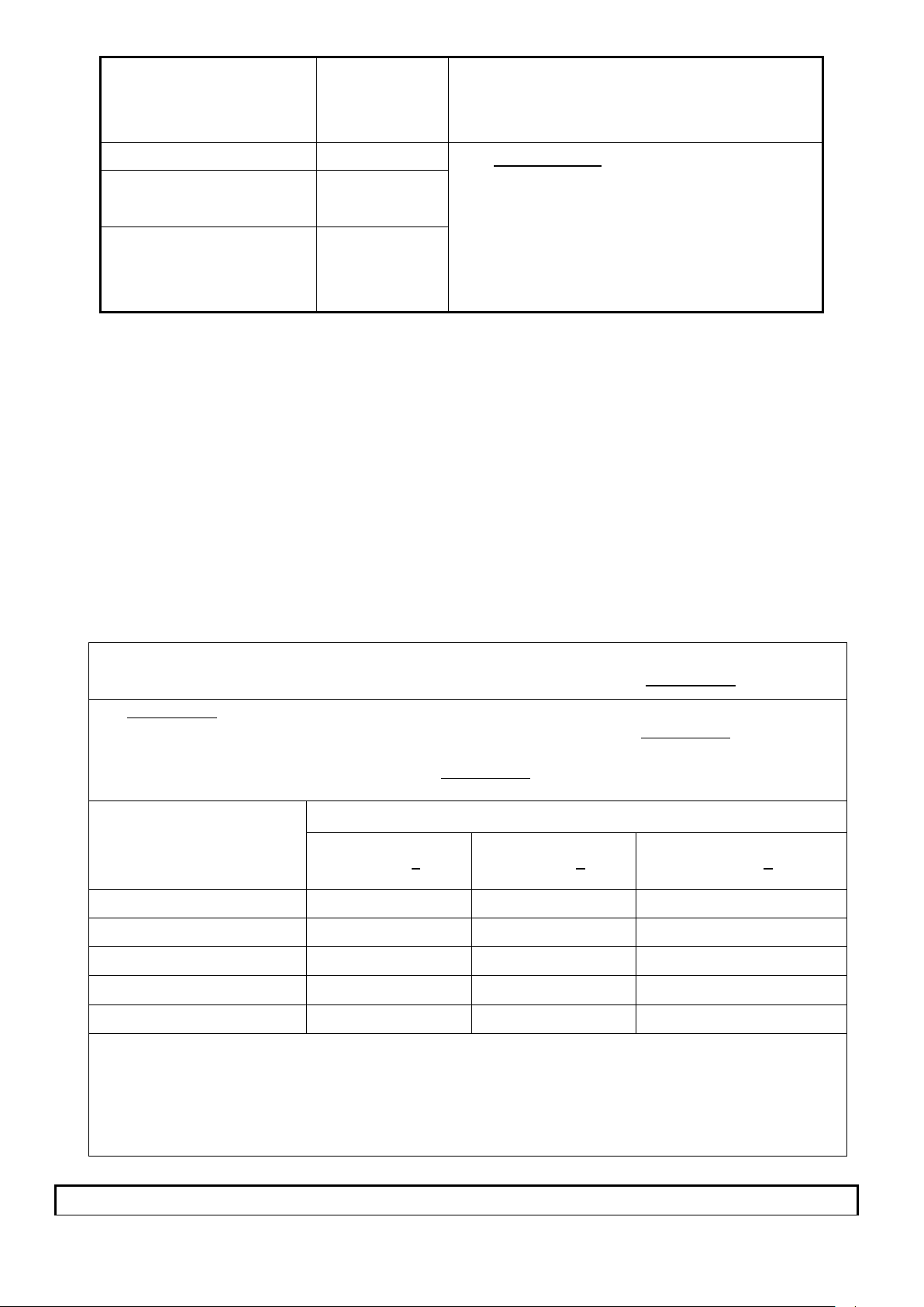
Recommended separation distance between
portable and mobile RF communications equipment and the Ai1-Premium
which radiated RF disturbances are controlled. The customer or the user of the Ai1-Premium can help
prevent electromagnetic interference by maintaining a minimum distance between portable and mobile RF
communications equipment (transmitters) and the Ai1-Premium as recommended below, according to the
power of transmitter
W
0,01 0,12 0,12 0,23
0,1 0,38 0,38 0,73
1 1,2 1,2 2,3
10 3,8 3,8 7,3
150 kHz to 80 MHz
d =1,2√P
80 MHz to 800 MHz
d =1,2√P
800 MHz to 2,7 GHz
d =2,3√P
100 12 12 23
in meters (m) can be estimated using the equation applicable to the frequency of the transmitter, where p is
the maximum output power rating of the transmitter in watts (W) according to the transmitter manufacturer.
NOTE1 At 80 MHz and 800 MHz, the separation distance for the higher frequency range applies.
NOTE2 These guidelines may not apply in all situations. Electromagnetic propagation is affected by
Manufacturer’s declaration-electromagnetic immunity
26
Page 33
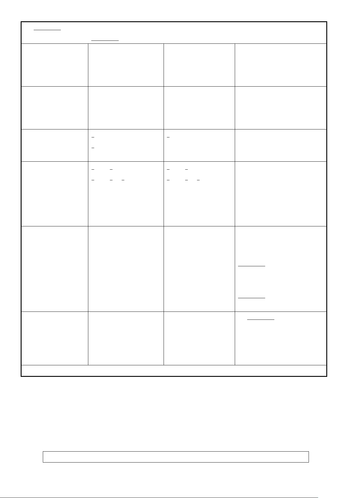
The Ai1-Premium is intended for use in the electromagnetic environment (for professional healthcare) specified below.
The customer or the user of the Ai1-Premium should assure that it is used in such an environment.
Immunity test IEC 60601
Electrostatic discharge(ESD)
IEC 61000-4-2
Electrical fast transient/burst
IEC 61000-4-4
Surge
IEC 61000-4-5
Contact:±8 kV
Air±2 kV,±4 kV,±8 kV,±15 kV
+ 2kV for power supply lines
+ 1kV for input/output lines
+ 0.5kV, +1kV line(s) to line(s)
+ 0.5kV, +1kV,+ 2kV line(s) to
earth
test level
Compliance level Electromagnetic
environment-guidance
(for professional healthcare
environment)
Contact:±8 kV
Air±2 kV,±4 kV,±8 kV,±15 kV
+ 2kV for power supply lines
Not applicable
0.5kV, +1kV line(s) to line(s)
+
+ 0.5kV, +1kV,+ 2kV line(s) to
earth
Floors should be wood, concrete or
ceramic tile. If floors are covered with
synthetic material, the relative humidity
should be at least 30%
Mains power quality should be that of a
typical professional healthcare
environment.
Mains power quality should be that of a
typical professional healthcare
environment.
Voltage Dips, short
interruptions and voltage
variations on power supply
input lines
IEC 61000-4-11
Power frequency(50, 60 Hz)
magnetic field
IEC 61000-4-8
NOTE UT is the a.c. mains voltage prior to application of the test level.
Voltage dips:
T; 0,5 cycle
0 % U
T; 1 cycle
0 % U
T; 25/30 cycles
70 % U
Voltage interruptions:
T; 250/300 cycle
0 % U
30 A/m
50 Hz or 60 Hz
Voltage dips:
T; 0,5 cycle
0 % U
T; 1 cycle
0 % U
T; 30 cycles
70 % U
Voltage interruptions:
T; 300 cycle
0 % U
30 A/m
60 Hz
Mains power quality should be that of a
typical professional healthcare
environment. If the user of the
Ai1-Premium
operation during power mains
interruptions, it is recommended that the
Ai1-Premium be powered from an
uninterruptible power supply or a battery.
The Ai1-Premium power frequency
magnetic fields should be at levels
characteristic of a typical location in a
typical professional healthcare
environment.
requires continued
Manufacturer’s declaration-electromagnetic immunity
27
Page 34
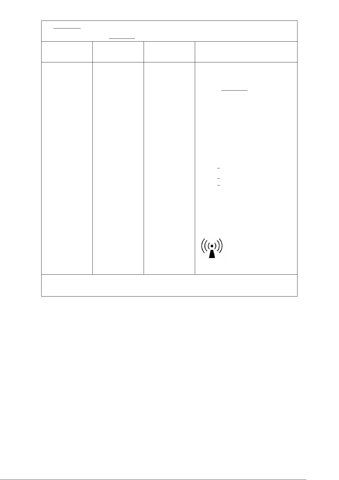
The Ai1-Premium is intended for use in the electromagnetic environment (for professional healthcare) specified below.
from structures, objects and people.
The customer or the user of the Ai1-Premium should assure that it is used in such and environment.
Immunity test IEC 60601 test level Compliance level Electromagnetic environment-guidance
(for professional healthcare environment)
Conducted RF
IEC 61000-4-6
Radiated RF
IEC 61000-4-3
:
3 Vrms
0,15 MHz – 80 MHz
:
6 Vrms
in ISM bands between
0,15 MHz and 80 MHz
80 % AM at 1 kHz
3 V/m
80 MHz – 2,7 GHz
80 % AM at 1 kHz
:
3 Vrms
0,15 MHz – 80 MHz
:
6 Vrms
in ISM bands between
0,15 MHz and 80 MHz
80 % AM at 1 kHz
3 V/m
80 MHz – 2,7 GHz
80 % AM at 1 kHz
Portable and mobile RF communications
equipment should be used no closer to any
part of the Ai1-Premium
the recommended separation distance
calculated from the equation applicable to the
frequency of the transmitter.
Recommended separation distance:
d = 1,2 √P
d = 1,2 √P
d = 2,3 √P
Where P is the maximum output power rating of
the transmitter in watts (W) according to the
transmitter manufacturer and d is the
recommended separation distance in metres
(m).
Interference may occur in the vicinity of
equipment marked with the following symbol:
80MHz to 800 MHz
800MHz to 2,7 GHz
including cables, than
NOTE1 At 80 MHz and 800 MHz, the higher frequency range applies.
NOTE2 These guidelines may not apply in all situations. Electromagnetic propagation is affected by absorption and reflection
28
Page 35
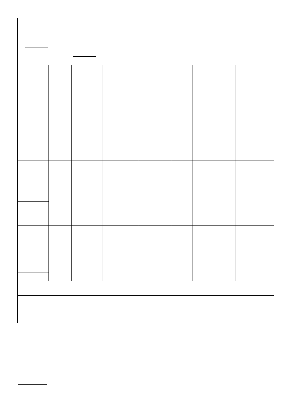
Manufacturer’s declaration-electromagnetic immunity
The
The customer or the user of the
Maximum power
ME
Test specifications for
Ai1-Premium is intended for use in the electromagnetic environment (for professional healthcare) specified below.
Ai1-Premium should assure that it is used in such an environment.
Test frequency
(MHz)
385
450
710
745
780
810
870
930
a)
Band
(MHz)
380 –390
430 – 470
704 – 787
800 – 960
Service
TETRA 400
GMRS 460,
FRS 460
LTE Band 13,
GSM 800/900,
TETRA 800,
iDEN 820,
CDMA 850,
LTE Band 5
ENCLOSURE PORT IMMUNITY to RF wireless communications equipment
a)
Modulation b)
±5 kHz deviation
17
Pulse
modulation b)
18 Hz
FM c)
1 kHz sine
Pulse
modulation b)
217 Hz
Pulse
modulation b)
18 Hz
(W)
1,8 0,3 27 27
2 0,3 28 28
0,2 0,3 9 9
2 0,3 28 28
Distance
(m)
IMMUNITY TEST
LEVEL
(V/m)
Compliance LEVEL
(V/m)
(for professional
healthcare)
1 720
1 845
1 970
2 450
5 240
5 500
5 785
NOTE If necessary to achieve the IMMUNITY TEST LEVEL, the distance between the transmitting antenna and the ME EQUIPMENT or
SYSTEM may be reduced to 1 m. The 1 m test distance is permitted by IEC 61000-4-3.
a)
For some services, only the uplink frequencies are included.
b)
The carrier shall be modulated using a 50 % duty cycle square wave signal.
c)
As an alternative to FM modulation, 50 % pulse modulation at 18 Hz may be used because while it does not represent actual
modulation, it would be worst case.
1 700 –
1 990
2 400 –
2 570
5 100 –
5 800
GSM 1800;
CDMA 1900;
GSM 1900;
DECT;
LTE Band 1, 3,
4, 25; UMTS
Bluetooth,
WLAN,
802.11 b/g/n,
RFID 2450,
LTE Band 7
WLAN 802.11
a/n
modulation b)
modulation b)
modulation b)
Pulse
2 0,3 28 28
217 Hz
Pulse
2 0,3 28 28
217 Hz
Pulse
0,2 0,3 9 9
217 Hz
Warranty
29
Page 36

The Prius Healthcare USA Ai1 bed is guaranteed for a period of one year from the date of delivery,
against defects in materials and workmanship, under normal use and service.
This one-year warranty includes all mechanical and electrical components.
Steel structural components on beds are covered under warranty for a period of 10 years from the
date of delivery.
Damage caused by use in unsuitable environmental conditions, abuse or failure to maintain the
product in accordance with user and service instructions is not covered.
Any alteration, modification, or repair unless performed by or authorized in writing by Prius
Healthcare USA, will void this warranty.
Parts
Prius Healthcare USA beds contain various parts that wear from normal use. These parts, such as
DC batteries, are not covered under the one-year warranty, but are covered for 90 days after date
of delivery. A parts list is available upon request.
Prius Healthcare USA’s obligation under this warranty is limited to supplying replacement parts,
servicing or replacing, at its option, any product which is found by Prius Healthcare USA to be
defective.
Warranty replacement parts are covered by the terms of this warranty until the product’s original
one-year warranty period expires.
When requested by Prius Healthcare USA, parts must be returned for inspection at the customer’s
expense. Credit will be issued only after inspection.
Service
Most service requests can be handled by the facility Maintenance Department with assistance from
the Prius Healthcare USA.
Should a technician be required, one will be provided by Prius Healthcare USA, at our discretion.
Only the Prius Healthcare USA can dispatch authorized technicians.
This warranty is extended to the original purchaser of the equipment.
For service, maintenance, warranty and any questions regarding this product, please contact.
30
 Loading...