

PRITY MA18, GA26, LB, GA33, SLB Technical Data Manual
RESIDENTIAL BOILERS FOR SOLID FUEL
TECHNICAL DATA
The boilers are intended to be installed in ground premises with a possibility of easy
refueling with coal.
They are intended for heating in systems with local heat-supply, as well as for warming up
of household drinking water.
Model Maximum heat
power, kW
MA18 19 1,5 22 35
GA 26 28 1,5 25 62
GA33 36 1,5 30 70
LB 44 2,5 30 84
SLB 36 2,5 30 64
Max. pressure of
the water, bar
Minimum draught,
Pa
Volume of the
water jacket, l
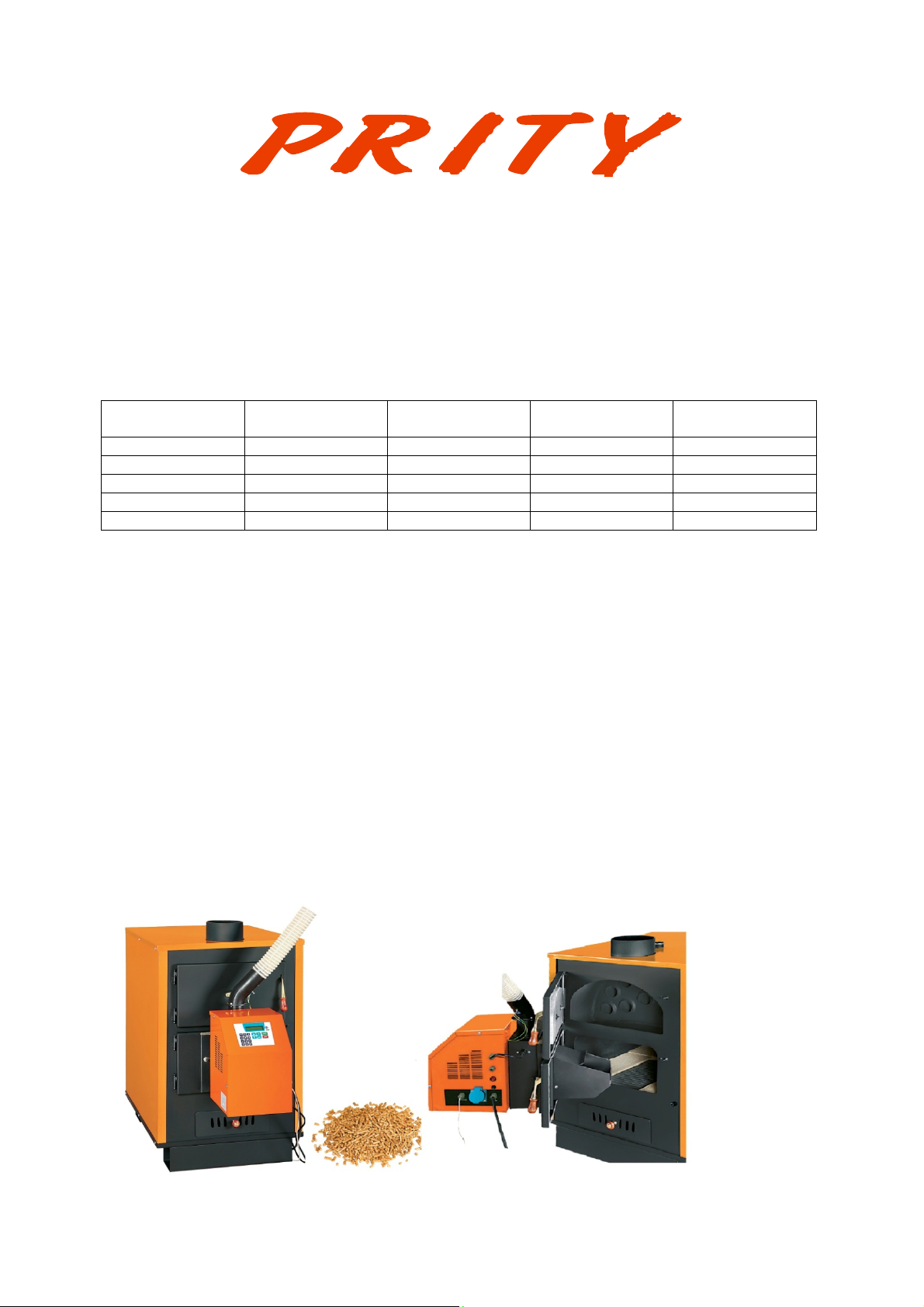
The boilers consist of the following elements:
The main part the boiler is the heat exchanger. The heat exchanger represents a welded construction of
steel sheet material. In its lower part a combustion chamber is formed.
The ash-pan is set under the combustion chamber. The ash residue is gathered and allows simplified
operation when cleaning of the equipment.
The input orifice (nozzle) is located above and the output orifice (nozzles) - in the in the back part of
the boiler and represent two terminals with external thread G 1 "(G 1
which the boiler is connected to the heating system.
The chimney stack is located at the top of the boiler and used lead away the flue gases through a
chimney.
The steel heat exchanger is insulated with mineral insulation, which limits the heat loss to the
environment.
The external decorative side panels are made of steel sheet and are coloured powder coated.
The boilers PRITY LB PRITY SLB and have the possibility to work with wood pellets after
installation of the respective pellet burner on the door of the combustion chamber.
1/4
" for LB and SLB), through

In this case they have the following characteristics:
PRITY LB PRITY SLB
Necessary draught of the chimney, Pa 30 30
Water content, l 84 64
Temperature of the flue gases at nominal heat power, °C 309 300
Diameter of the chimney stack, mm 150 150
Nominal heat power, kW 40 33
Minimum heat power, kW 15 15
Efficiency, % 80 82
Average emission of CO, % 0,32 0,32
Average dust emission, mg/m3 58 56
Class boiler 1 1
Set range of temperature controller, °C 30÷80 30÷80
Type of the fuel – wooden pellets with humidity till 10% Wooden pellets with
humidity till 10%
Wooden pellets with
humidity till 10%
INSTALLATION INSTRUCTIONS
The boiler is placed on a stable fireproof horizontal floor. To protect the floor, a stable fireproof
base can be used, which shall stick out before the boiler at least 50 cm in front and 30 cm at the side.
In the radiating area of the boiler, at a distance of 80 cm around it no objects burnable and
damageable by the radiated heat shall be there.
Before connecting the boiler to the chimney, consult a specialist.
The connecting elements (rosette and chimney) must be fixed tightly and firmly, so that they may
not get into in the passage section of the chimney. The smoking pipes shall have the same size as the
connecting pipe of the boiler.
It is advisable that the boiler work with a separate chimney. If other heating appliances are
connected to the same chimney, it must be calculated for that.
3
Fresh air must get in the boiler at least 4 m
/h for each kilowatt from its heat output. When
necessary a flow from adjacent premises or outside air is ensured.
The burning process of the boiler must not feel shortage of air on the action of gravitational or
forced aspirations, since this is a prerequisite for insufficient combustion or returning of flue gases in
the premises.
It follows a connection of the water-hating pellet boiler to the heating installation through
suitable fittings and fixture according to the prepared beforehand thermo-technical project.
The requirements for installation of the pellet burner and the feeder screw
(auger) for fueling from a tank to the burner are given in its manual for
installation and operation.
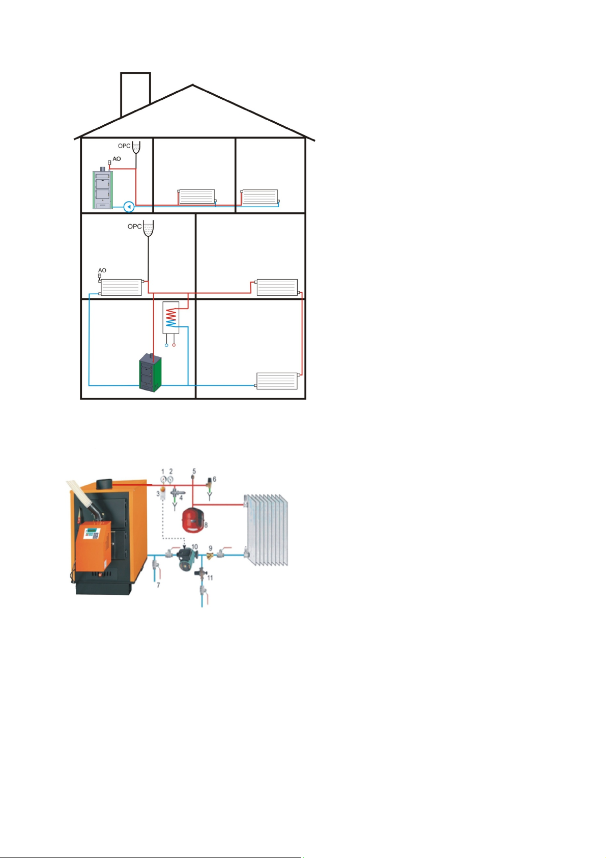
EXEMPLARY DIAGRAMS OF
OPERATION OF A BOILER IN
AN OPEN SYSTEM
Open water heating system with an open
expansion vessel and a pump
Economical open gravitational self-adjusting
water heating system with an open expansion
vessel without a pump.
EXEMPLARY DIAGRAM OF OPERATION
OF A BOILER
IN A CLOSED SYSTEM
1. Manometer
2. Thermometer 120º С.
3. Electrical thermostat.
4. Thermal safety valve.
5. Automatic deaerator.
6. Safety hydraulic valve
7. Drainage.
8. Closed expansion vessel.
9. Filter.
10. Circulation pump.
11. Automatic supplementing group
GENERAL RULES AND RECOMMENDATIONS
1. Before the building of the installation, it is recommended that the heat losses be calculated by a
specialist for the concrete case.
2. With an open system the installation must be connected to the atmosphere with an open expansion
vessel. Between the boiler and the expansion vessel no stop elements must be fixed.
3. De-aeration of each branch and element of the installation in each moment of its operation shall be
ensured.
 Loading...