

Page 1

MASELEC MASTER SERIES
MEA-2 Precision Stereo Equalizer
Operation Manual
Issue 1.2 17 January 2000
Page 2

Prism Media Products Limited Operation Manual
MASELEC MASTER SERIES MEA-2 Precision Stereo Equalizer
CONTENTS
1. INTRODUCTION ..............................................4
2. SUMMARY OF MEA-2 FEATURES ................................4
3. GETTING STARTED ...........................................5
3.1. Unpacking your MEA-2 ....................................5
3.2. Using the MEA-2 for the first time ............................5
3.3. MEA-2 product concept and capabilities .......................6
4. OPERATION .................................................7
4.1. Shelf/bandwidth and boost/cut settings ........................8
4.2. Frequency selections by Eq band ............................9
5. CONNECTORS ..............................................10
5.1. Input connections .......................................10
5.2. Output connections ......................................11
5.3. Rear panel connectors ...................................12
6. SPECIFICATION .............................................12
6.1. Analogue inputs ........................................12
6.2. Analogue outputs .......................................12
6.3. Performance specification .................................13
6.4. Servicing and repair .....................................13
6.5. Mains transformer voltage selection .........................13
6.6. Fuse .................................................14
6.7. Earthing ...............................................14
6.8. Physical dimensions .....................................14
7. EQUALIZER RESPONSE CURVES ..............................15
7.1. Range of cut/boost for 60Hz shelf on LF1 .....................15
7.2. Range of cut/boost for 60Hz bell curve on LF1 .................15
7.3. Range of frequency for +8dB shelf on LF1 ....................16
7.4. Range of bandwidths for +8dB 530Hz bell on LF1 ..............16
7.5. Range of bandwidth and shelf curve at 435Hz on LF1 ...........17
Issue 1.2 © Prism Media Products Limited
17 January 2000 Page 2 of 20
Page 3

Prism Media Products Limited Operation Manual
MASELEC MASTER SERIES MEA-2 Precision Stereo Equalizer
7.6. Range of bandwidth and shelf curve at 108Hz on LF2 ...........17
7.7. Range of boost/cut for 617Hz shelf on HF1 ...................18
7.8. Range of boost/cut for 3300Hz shelf on HF1 ..................18
7.9. Range of bandwidth plus shelf curve at 617Hz on HF1 ..........19
7.10. Range of bandwidth plus shelf curve at 9000Hz on HF1 .........19
8. ELECTROMAGNETIC COMPATIBILITY ...........................20
9. REFERENCES ..............................................20
Manual Revision History
Issue 1.0; 23 October 1997
Issue 1.1; 8 January 1998
Issue 1.2; 17 January 2000 Detail changes only; email addr; Layout;
Product Revision History
This manual is for use with MEA-2 units having serial numbers beginning with ‘4' (or higher
number) thus : MEA-2-4-xx-xxxx
Issue 1.2 © Prism Media Products Limited
17 January 2000 Page 3 of 20
Page 4

Prism Media Products Limited Operation Manual
MASELEC MASTER SERIES MEA-2 Precision Stereo Equalizer
1. INTRODUCTION
The MEA-2 Precision Stereo Equalizer is intended for professional audio use in recording ,
mixing and mastering applications where high performance is required.
The MEA-2 provides a unique set of tools, carefully crafted to provide an equalizer whose
sonic character was the most important design objective.
The unique character of the device is evident in the response curves included at the end
of this manual.
The MEA-2 employs state-of-the art analogue electronics and provides a perfect solution
to analogue mastering needs, especially used in conjunction with Prism Sound A/D and
D/A converters.
Also available in the MASELEC MASTER SERIES is the MLA-2 compressor.
2. SUMMARY OF MEA-2 FEATURES
Operational:
C Four separate equalizer sections per channel
C EQ in/out for each channel
C All sections switchable between shelving & five different peaking responses
C Precision stepped controls
C Overlapping frequency ranges in each pair (LF1&2 and HF1&2)
C 84 frequency settings per channel
Technical:
C Low noise
C Extended headroom with maximum input amplitude of +28dBu
C Extended frequency response
C Low distortion
C Electronically balanced inputs and outputs
Issue 1.2 © Prism Media Products Limited
17 January 2000 Page 4 of 20
Page 5

Prism Media Products Limited Operation Manual
MASELEC MASTER SERIES MEA-2 Precision Stereo Equalizer
3. GETTING STARTED
It is not necessary to read all the manual before being able to use the MEA-2 Precision
Stereo Equalizer. This section contains all the information required for you to get going
straight away.
3.1. Unpacking your MEA-2
Check that you have the following items and that they are undamaged:
" MEA-2 Precision Stereo Equalizer unit
" MEA-2 Precision Stereo Equalizer operation manual (this book)
" IEC320 type mains lead with appropriate plug for your supply
Check that the slide switch mounted on the rear panel is set to the correct mains voltag e
range (‘120' setting : 90V-130Vac 50-60Hz; ‘240' setting : 180-260Vac 50-60Hz) and that
the plug fitted to the mains lead is of the correct type. If not, DO NOT CONNECT THE
MAINS SUPPLY, but contact your distributor.
Please keep the packaging for re-use in the event that the unit should be shipped to
another location or in the event that it should ever need to be returned to the manufacturer
for repair or upgrade.
3.2. Using the MEA-2 for the first time
Connect a source of balanced audio to the input connectors on the MEA-2. Refer to
section 10 for details of how to wire up interconnecting cables for the MEA-2.
Connect the output of the MEA-2 to a monitoring system or to a tape recorder input.
Connect the mains supply to the MEA-2 unit. There is a main power switch on the rear of
the unit and an auxiliary switch on the front which is more convenient to use if the
equipment is rack mounted and the rear panel is inaccessible. It is necessary for the rearmounted mains switch to be in the ‘ON’ position before the front panel switch will operate.
The front panel switch operates a relay within the unit.
The indicator lamp integral in the rear-mounted mains switch should illuminate when
switched on. If it fails to light the power may be absent or the unit may be faulty. Check the
mains supply, and try again. If the problem is still evident contact your distributor.
Issue 1.2 © Prism Media Products Limited
17 January 2000 Page 5 of 20
Page 6

Prism Media Products Limited Operation Manual
MASELEC MASTER SERIES MEA-2 Precision Stereo Equalizer
Switch the secondary power switch on the front of the MEA-2 to 'ON'. Press and release
the 'In/Out' push buttons for the left and right channels on the front of the unit. When the
equalizer for each channel is in-circuit, the button will be illuminated a soft green colour.
Switch the monitor selection to monitor the MEA-2 output.
The unit is now ready to use.
3.3. MEA-2 product concept and capabilities
The MEA-2 Precision Stereo Equalizer is designed to provide very high quality signal
processing for the most demanding professional applications. It has been carefully
developed in conjunction with balance engineers, producers and mastering engineers to
provide a natural and warm sound. Samples of the unique response curves of the MEA-2
are reproduced in section 7 of this manual.
The presentation of the controls is designed to be clear and intuitive.
Issue 1.2 © Prism Media Products Limited
17 January 2000 Page 6 of 20
Page 7

Prism Media Products Limited Operation Manual
MASELEC MASTER SERIES MEA-2 Precision Stereo Equalizer
4. OPERATION
The unit is designed for either stereo or 2-channel operation and each channel is controlled
independently by an identical set of controls.
Each channel has four equalizer sections, denoted in this manual as LF1, LF2, HF1 &
HF2. These are presented on the front panel in the same order as above with LF1 being
on the left.
Each section has controls for
C Response/Q
C Frequency
C Cut/Boost
These parameter adjustments are interactive to a degree; for example filter bandwidth is
adjusted automatically while adjusting the cut/boost control. For further information see the
sample curves in section 7.
For reference, the settings available on the unit are reproduced here:
Issue 1.2 © Prism Media Products Limited
17 January 2000 Page 7 of 20
Page 8

Prism Media Products Limited Operation Manual
MASELEC MASTER SERIES MEA-2 Precision Stereo Equalizer
4.1. Shelf/bandwidth and boost/cut settings
The numerical bandwidth settings relate to the Q factor or sharpness of the peaking filters.
As a result of the asymmetric shape of the MEA-2 Equalizer curves it becomes difficult to
define Q factor in a meaningful way. These settings should therefore be regarded as
indicating the relative bandwidths with 4 being the broadest and 20 the narrowest. For
more detail, see section 15.
All sections shelf/bandwidth settings:
Shelf, 4, 6, 9, 14, 20
All sections cut/boost settings (dB):
Boost (dB) Cut (dB)
+8.0 -8.0
+6.0 -6.0
+5.0 -5.0
+4.0 -4.0
+3.0 -3.0
+2.5 -2.5
+2.0 -2.0
+1.5 -1.5
+1.0 -1.0
+0.5 -0.5
0.0
Issue 1.2 © Prism Media Products Limited
17 January 2000 Page 8 of 20
Page 9

Prism Media Products Limited Operation Manual
MASELEC MASTER SERIES MEA-2 Precision Stereo Equalizer
4.2. Frequency selections by Eq band
LF1 (Hz) LF2 (Hz) HF1 (Hz) HF2 (Hz)
19 21 617 665
22 24 727 787
26 29 862 937
31 34 1k 1k1
37 41 1k2 1k3
43 48 1k4 1k5
51 57 1k7 1k8
60 67 2k0 2k2
71 79 2k4 2k6
84 92 2k8 3k0
98 108 3k3 3k6
114 126 3k9 4k2
134 148 4k6 5k0
158 173 5k4 5k9
185 203 6k4 7k0
218 240 7k6 8k2
258 280 9k0 9k7
305 332 11k 12k
364 400 13k 14k
435 477 17k 19k
530 572 24k 27k
Issue 1.2 © Prism Media Products Limited
17 January 2000 Page 9 of 20
Page 10
Prism Media Products Limited Operation Manual
MASELEC MASTER SERIES MEA-2 Precision Stereo Equalizer
5. CONNECTORS
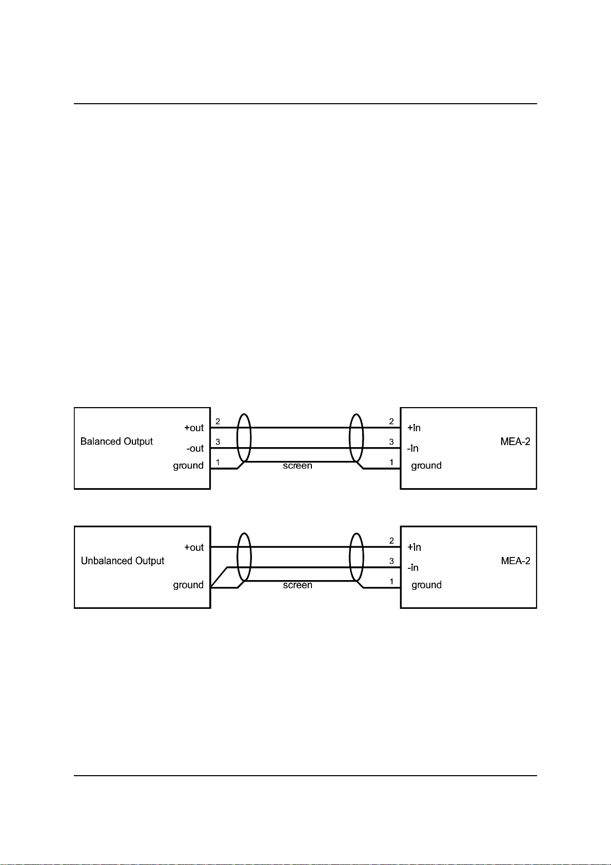
For this equipment, the convention for balanced XLR connections pin 2 is 'hot' or '+' and
pin 3 'cold' or '-'. Some users and equipment implement the opposite. This should not be
problematic providing a consistent implementation is used throughout.
Note: When interfacing to other devices such as A/D and D/A converters it may be
necessary to check the manufacturers polarity convention if the correct absolute phase
is to be maintained. However, this does not affect use of the MEA-2 with either polarity
convention.
Balanced analogue audio connections should use a good-quality screened twisted-pair
lead. Unbalanced connections must also be screened.
5.1. Input connections
The following diagrams illustrate correct connection for balanced and unbalanced sources:
Using the above method when driving the MEA-2 with unbalanced sources should provide
best results.
Note: The maximum input amplitude is reduced by approximately 6dB from the
nominal +28dBu when driving the MEA-2 from an unbalanced source.
Issue 1.2 © Prism Media Products Limited
17 January 2000 Page 10 of 20
Page 11
Prism Media Products Limited Operation Manual
MASELEC MASTER SERIES MEA-2 Precision Stereo Equalizer
5.2. Output connections
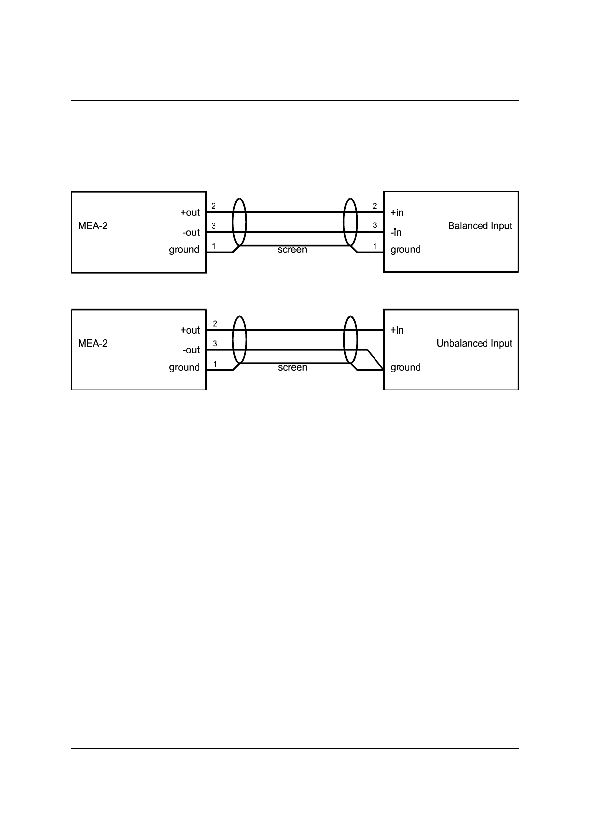
The following diagrams illustrate correct connection for balanced and unbalanced sources:
Using the above method for driving unbalanced loads should provide best results. It
employs ‘Ground Loop Compensation’ and the signal level remains unchanged compared
to balanced operation.
Note: When driving unbalanced loads with the MEA-2 the maximum output level is
reduced by approximately 6dB from the nominal +28dBu.
Issue 1.2 © Prism Media Products Limited
17 January 2000 Page 11 of 20
Page 12

Prism Media Products Limited Operation Manual
MASELEC MASTER SERIES MEA-2 Precision Stereo Equalizer
5.3. Rear panel connectors
A. Audio I/O
C Left Channel Input
C Left Channel Output
C Right Channel Input
C Right Channel Output
B. Earthing Stud - Link to a good-quality ground connection by the most direct route.
C. IEC Mains Inlet (Switched).
6. SPECIFICATION
6.1. Analogue inputs
The analogue inputs are on a three pin XLR connector with positive and negative signal
polarities on pins 2 and 3 respectively, and screen on pin 1. Pins 2 & 3 have a high
impedance path to the chassis earth.
Differential input impedance: 27 kS(*) (pin 2 to pin 3)
Single-ended input impedance: 27 kS(*) (pin 1 to 2 or 3)
Coupling impedance to chassis: 1.0 MS (chassis/pin 1 to 2 or 3)
Common-mode range: 20 Vrms
* Note : Some earlier units are 38.4 kS
6.2. Analogue outputs
The analogue outputs are on a three pin XLR connector with positive and negative signal
polarities on pins 2 and 3 respectively, and the mid-point on pin 1.
Differential output impedance: 62 S (pin 2 to pin 3, balanced)
Single-ended output impedance: 31 S (pin 1 to 2 or 3, unbalanced)
Issue 1.2 © Prism Media Products Limited
17 January 2000 Page 12 of 20
Page 13

Prism Media Products Limited Operation Manual
MASELEC MASTER SERIES MEA-2 Precision Stereo Equalizer
6.3. Performance specification
Specifications quoted in this section are to AES17-1991 (ANSI S4.51-1991) [Ref. 1], with
input level set to +22dBu except where stated. For ‘EQ in’ measurements, the CH1/CH2
‘In’ buttons are illuminated and other settings are : LF1 - Shelf, LF2 - Bell, slope 9, HF1
Bell, slope 9, HF2 Shelf. Gain for each section is set to 0dB.
Maximum input amplitude : +28dBu
Output noise : EQ out < -97dBu
EQ in < -89dBu
Frequency response : + 0.1, -0.4dB, <1Hz to > 50 kHz
Crosstalk : less than -100 dB, 20 Hz to 20 kHz
Un-driven input terminated 150R
Harmonic distortion and noise, EQ in : <-105dB (<0.0006%), 997 Hz
Dynamic range : (Measured at -32dBu) EQ out > 125dB
EQ in > 117dB
6.4. Servicing and repair
There are no user serviceable parts inside this unit. Repairs should only be undertaken
by qualified electronics technicians or engineers.
6.5. Mains transformer voltage selection
The mains transformer has a tapped primary to allow operation at nominal voltages of
120V or 240V. A rear-panel slide switch selects the mains voltage range. Ensure that
the correct voltage range is selected before using the MEA-2.
6.5.1. Mains voltage range : 90-130V (nominally 120V) or 180-260V
(nominally 240V) operation. The selected
supply voltage range is indicated on the rear
panel slide switch.
6.5.2. Power consumption : 15W max.
Issue 1.2 © Prism Media Products Limited
17 January 2000 Page 13 of 20
Page 14

Prism Media Products Limited Operation Manual
MASELEC MASTER SERIES MEA-2 Precision Stereo Equalizer
6.6. Fuse
There is one mains fuse, accessible externally in the IEC320 mains inlet. If this fuse is
blown it should be replaced by an identical value and type. (20x5mm 250V 315mAT
(anti-surge, slow)).
6.7. Earthing
The unit has an internal link connecting the audio ground to the chassis. A chassis earth
stud is provided on the rear of the unit.
6.8. Physical dimensions
Weight : 11 lb (5 kg)
Width : 19 inch (483mm) (rack-mountable)
Height : 3U (77mm)
Depth : 10.5 inches (267mm) front face to rear face. (Add clearance for
connectors)
Issue 1.2 © Prism Media Products Limited
17 January 2000 Page 14 of 20
Page 15
Prism Media Products Limited Operation Manual
MASELEC MASTER SERIES MEA-2 Precision Stereo Equalizer
7. EQUALIZER RESPONSE CURVES
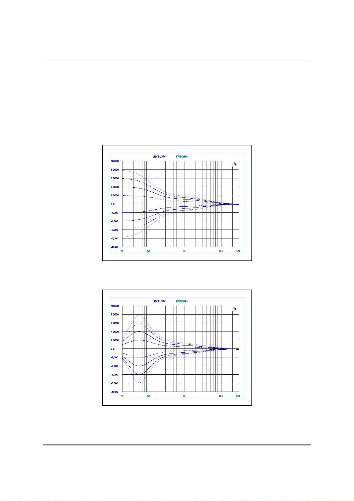
The following plots are samples of the responses of the MEA-2 equalizer. All section
types are represented, but for brevity only a small selection of the total number of
possible settings are included.
7.1. Range of cut/boost for 60Hz shelf on LF1
AUDIO PRECISION MEA_2GB1 vs 09 JUN 97 13:35:04
7.2. Range of cut/boost for 60Hz bell curve on LF1
AUDIO PRECISION MEA_2GB1 vs 09 JUN 97 13:35:04
Issue 1.2 © Prism Media Products Limited
17 January 2000 Page 15 of 20
Page 16
Prism Media Products Limited Operation Manual
MASELEC MASTER SERIES MEA-2 Precision Stereo Equalizer
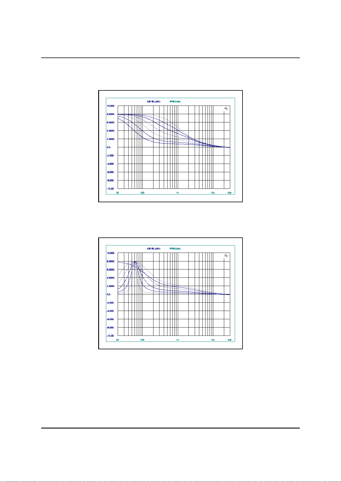
7.3. Range of frequency for +8dB shelf on LF1
AUDIO PRECISION MEA_2GB1 vs 09 JUN 97 13:35:04
7.4. Range of bandwidths for +8dB 530Hz bell on LF1
AUDIO PRECISION MEA_2GB1 vs 09 JUN 97 13:35:04
Issue 1.2 © Prism Media Products Limited
17 January 2000 Page 16 of 20
Page 17
Prism Media Products Limited Operation Manual
MASELEC MASTER SERIES MEA-2 Precision Stereo Equalizer
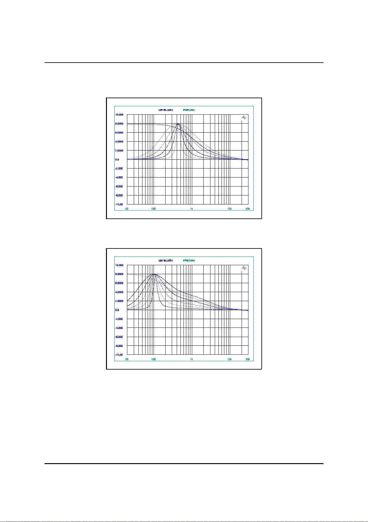
7.5. Range of bandwidth and shelf curve at 435Hz on LF1
AUDIO PRECISION MEA_2GB1 vs 09 JUN 97 13:35:04
7.6. Range of bandwidth and shelf curve at 108Hz on LF2
AUDIO PRECISION MEA_2GB1 vs 09 JUN 97 13:35:04
Issue 1.2 © Prism Media Products Limited
17 January 2000 Page 17 of 20
Page 18
Prism Media Products Limited Operation Manual
MASELEC MASTER SERIES MEA-2 Precision Stereo Equalizer
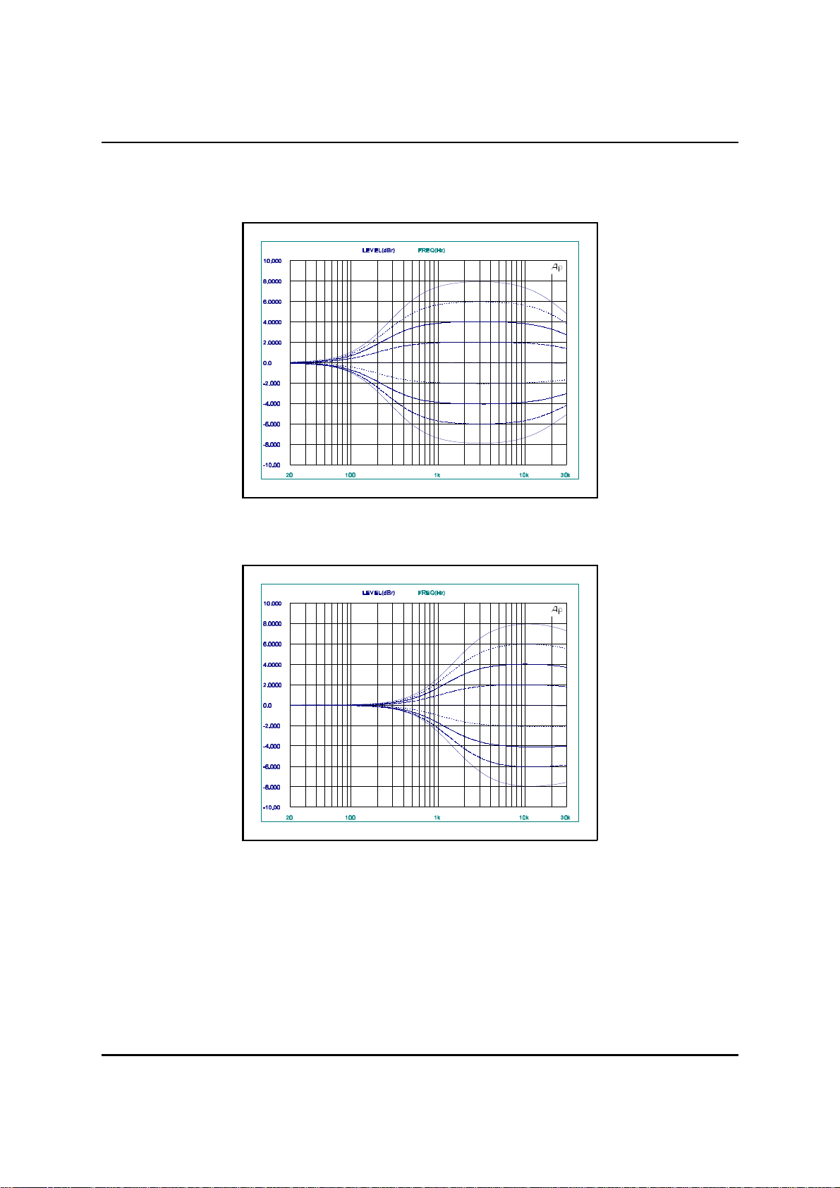
7.7. Range of boost/cut for 617Hz shelf on HF1
AUDIO PRECISION MEA_2GB1 vs 09 JUN 97 13:35:04
7.8. Range of boost/cut for 3300Hz shelf on HF1
AUDIO PRECISION MEA_2GB1 vs 09 JUN 97 13:35:04
Issue 1.2 © Prism Media Products Limited
17 January 2000 Page 18 of 20
Page 19
Prism Media Products Limited Operation Manual
MASELEC MASTER SERIES MEA-2 Precision Stereo Equalizer
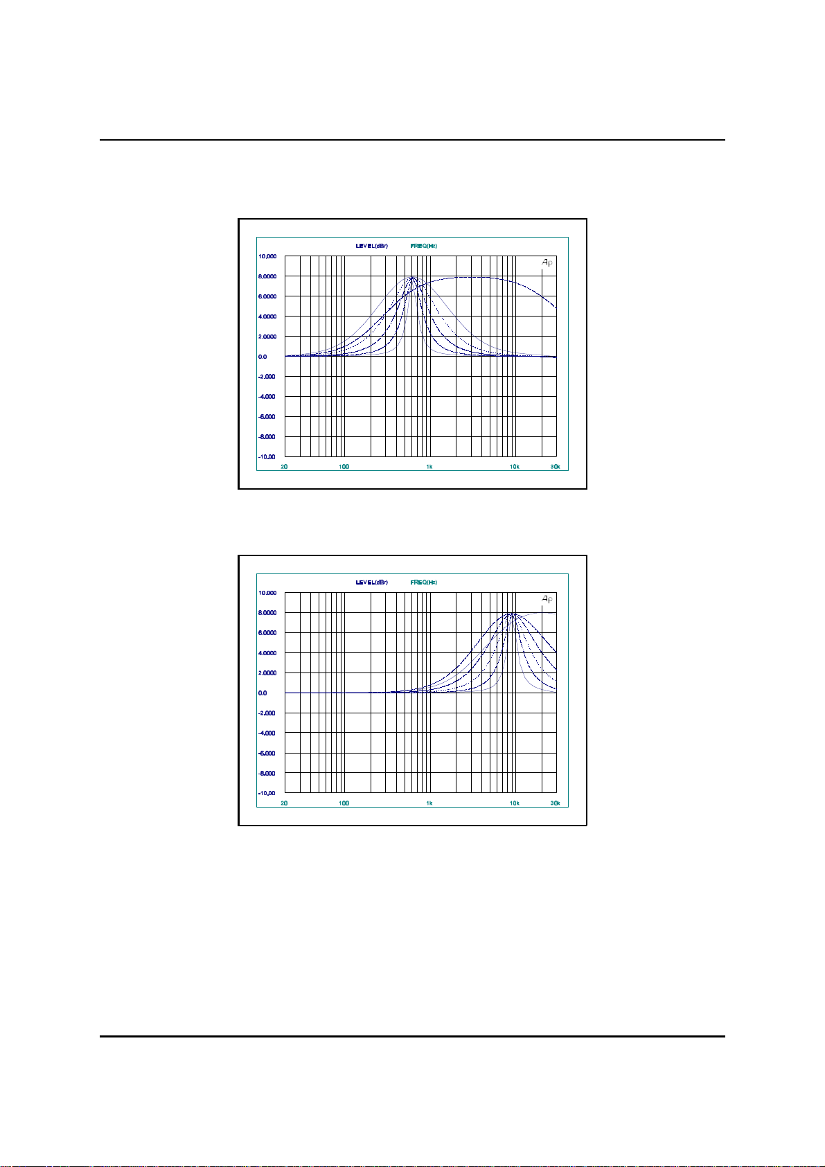
7.9. Range of bandwidth plus shelf curve at 617Hz on HF1
AUDIO PRECISION MEA_2GB1 vs 09 JUN 97 13:35:04
7.10. Range of bandwidth plus shelf curve at 9000Hz on HF1
AUDIO PRECISION MEA_2GB1 vs 09 JUN 97 13:35:04
Issue 1.2 © Prism Media Products Limited
17 January 2000 Page 19 of 20
Page 20

Prism Media Products Limited Operation Manual
MASELEC MASTER SERIES MEA-2 Precision Stereo Equalizer
8. ELECTROMAGNETIC COMPATIBILITY
This equipment is intended for use in an electromagnetically controlled environment. To
maintain the performance specification it should not be subject to strong magnetic
fields (such as in the immediate vicinity of a power amplifier or cathode ray tube) and all
connections should be terminated as described below. This equipment does not
include digital circuitry or generate high-frequencies that could be radiated or
conducted from the unit.
All XLR connections should use a screened twisted pair cable with the screen
connected to pin 1 of the XLR connector at both ends.
9. REFERENCES
[1] AES17-1991 - `AES Standard Method for Digital Audio Engineering - Measurement of Digital Audio Equipment' J.
Audio Eng. Soc., Vol. 39 No. 12, pp 961-975 (December 1991)
FURTHER INFORMATION
Enquiries about this product should be addressed to :
Prism Media Products Limited
William James House
Cowley Road
Cambridge
Phone: +44-(0)1223-424 988
Fax: +44-(0)1223-425 023
Email : [email protected],
Web : www.prismsound.com
CB4 0WX
UK
Issue 1.2 © Prism Media Products Limited
17 January 2000 Page 20 of 20
 Loading...