

Page 1
Professional D/A converter
Operation Manual
Issue 1.0 25 August 1998
Page 2

Prism Media Products Limited Dream
Operation Manual
CONTENTS
1. INTRODUCTION ..............................................4
2. SUMMARY OF DA-2 FEATURES .................................4
3. GETTING STARTED ...........................................5
3.1. Unpacking your DA-2 .....................................5
3.2. Using the DA-2 for the first time .............................5
3.3. DA-2 product concept and capabilities ........................7
3.4. Dynamic Range Enhancement (DRE) .........................7
4. OPERATION .................................................8
4.1. Normal mode controls .....................................8
4.2. Set Inputs mode .........................................9
4.3. Set Level mode .........................................11
4.4. Set Master mode ........................................12
5. FRONT-PANEL INDICATORS ..................................13
5.1. Input selection or maximum output level setting indicators ........13
5.2. 32kHz, 44.1kHz and 48kHz indicators .......................13
5.3. `X2' indicator ...........................................14
5.4. `Master' indicator ........................................14
6. CONNECTORS ..............................................15
6.1. Analogue output connectors ...............................15
6.2. Interconnect screens - the pin 1 conditions ....................15
6.3. Connector table .........................................16
7. SPECIFICATION .............................................17
7.1. Digital Inputs ...........................................17
7.2. Synchronization .........................................20
7.3. Digital Outputs ..........................................21
7.4. Analogue Outputs .......................................24
7.5. Performance Specification ................................25
7.6. Power ................................................27
7.7. Physical Dimensions .....................................27
8. INTERNAL CONFIGURATION OPTIONS AND FUSES ...............28
8.1. Fuses ................................................28
8.2. PCB jumper links ........................................28
8.3. Mains transformer voltage selection .........................29
Issue 1.0 © Prism Media Products Limited
25 August 1998 Page 2 of 30
Page 3

Prism Media Products Limited Dream
Operation Manual
9. ELECTROMAGNETIC COMPATIBILITY ...........................29
10. REFERENCES ..............................................30
Manual Revision History
25 August 1998 Issue : 1.0 ; Original Issue
Product Revision History
August 1998 Hardware revision A
Prism Media Products Limited
William James House
Cowley Road
Cambridge
CB4 4WX
UK
Phone: +44-(0)1223-424988
Fax: +44-(0)1223-425023
Email: [email protected]
Web: http://www.prismsound.com
Issue 1.0 © Prism Media Products Limited
25 August 1998 Page 3 of 30
Page 4

Prism Media Products Limited Dream
Operation Manual
1. INTRODUCTION
The Dream is a 24-bit, 96kHz-capable digital-to-analogue converter intended for
professional audio use in applications where a very high performance is required; for
monitoring, for example in the production of high quality masters, or for conditions such as
live recording where a large headroom may be required.
The Prism Sound Dynamic Range Enhancement (DRE) system is also incorporated fo r
use in monitoring and/or decoding a DRE encoded source.
2. SUMMARY OF DA-2 FEATURES
• 24-bit input resolution
• Sampling rates to 96kHz
• 114 dB A-weighted dynamic range
• Less than -104 dB THD+N at full scale (0.0006%)
• Flat low frequency response (-0.05 dB at 5.0 Hz)
• Floating balanced outputs
• Calibrated maximum output level adjustment:
+5 dBu to +28 dBu in 1 dB steps
Fine trim in steps of 0.05dB
• DRE decoding to analogue and digital outputs
• Input selection from seven stereo inputs
• Digital inputs in AES3, AES3 'Split96', SPDIF, Optical, AES-3ID coax, and SDIF-2
formats
• Digital outputs in AES3, SPDIF, Optical, and SDIF-2 formats simultaneously; also
AES3 'Split96' capability
• Digital interface format conversion
• Mute control on front panel
• Invert control on front panel
• De-emphasis of emphasised signals (Both CD and J17 characteristics)
• Low jitter, high precision clock with:
Capture range better than IEC958 specification (±1500ppm)
Excellent jitter tolerance ( >200ns at 2kHz)
Excellent jitter rejection (-60dB at 500Hz)
• Clock master mode
Issue 1.0 © Prism Media Products Limited
25 August 1998 Page 4 of 30
Page 5

Prism Media Products Limited Dream
Operation Manual
3. GETTING STARTED
It is not necessary to read all the manual before being able to use the Dream . This
section contains all the information required for you to get going straight away.
3.1. Unpacking your DA-2
Check that you have the following items and that they are undamaged:
" Dream converter unit
" Dream operation manual (this book)
" IEC320 type mains lead with appropriate plug for your supply
Check that your unit carries a label on the rear panel indicating the correct mains voltag e
for your application area and that the plug fitted to the mains lead is of the correct type. If
not, DO NOT CONNECT THE MAINS SUPPLY, but contact your distributor.
Please keep the packaging for re-use in the event that the unit should be shipped to
another location or in the event that it should ever need to be returned to the manufacturer
for repair or upgrade.
3.2. Using the DA-2 for the first time
Connect a digital audio source to one of the inputs on the DA-2.
3.2.1. AES or SPDIF sources
Source equipment operating at any of the standard rates from 32kHz to 96kHz may be
connected to any of the inputs including the BNC connectors.
3.2.2. Higher sampling-rate sources using “Split96" or “2-wire” format
For Split96 (2-wire) sources you must use inputs 2 and 3 in the DA-2 “Split96" mode as
only these inputs can handle this format. Input 2 will be routed to the left output channel and
Input 3 will be routed to the right channel.
3.2.3. SDIF-2 format
If the source is in the Sony Digital Interface Format (SDIF-2) then the three BNC inputs,
labelled L, R and WCK need to be used. [The L & R inputs are dual function and auto-
sensing, so SDIF-2, AES3-ID and SPDIF signals can be connected.]
Note: For more information about configuration of DA-2 inputs, refer to section 4.2.
Issue 1.0 © Prism Media Products Limited
25 August 1998 Page 5 of 30
Page 6

Prism Media Products Limited Dream
Operation Manual
3.2.4. Output connector wiring
The analogue outputs of the DA-2 are wired as follows:
pin 1 Screen and mid-point of balanced output
pin 2 Balanced output (Hot or `+')
pin 3 Balanced output (Cold or `-')
Conventional connections to a balanced analogue input should use a screened twisted
pair lead. The DA-2 output pins 2 and 3 should be wired to the two conductors of the pair
and pin 1 to the cable screen. The other end of the cable should be connected in a similar
manner.
3.2.5. Connecting the DA-2 to unbalanced inputs
For optimum performance the DA-2 should be connected to an unbalanced input using
only pins 1 and 2. Pin 2 should connect to the signal conductor and pin 1 should connect
to the ground or return. The signal level is then halved.
NOTE : Use of output pin 3 instead of 2 will result in phase inversion.
[It is possible to drive unbalanced inputs from pins 2 and 3 but this unbalances the
output and can lead to hum. In any case do not connect any of the three output pins to
each other].
3.2.6. Powering up for the first time
Connect the mains supply and switch on the DA-2 unit.
The front-panel LEDs should all illuminate momentarily; if any of them fails to light it may
be faulty. If so then check again by turning the unit off and on. If the problem is still evident
contact your distributor.
After the unit has initialised one of the seven input selection lights on the left of the front
panel will illuminate to indicate the selected input. This indicator will be steadily on if the
signal at the selected input is being decoded without error. It will flash if a signal is not
detected, and briefly extinguish when individual errors are detected. To select a different
input press the round select push-button on the left hand side of the front panel.
When you have selected the input you require then, if the signal is decoded correctly and
the unit is configured to the factory default settings, then only the appropriate sample rate
indicator and the input selection indicator will be steadily on. This indicates that the unit
is now operating correctly. If the output level needs adjustment refer to section 4.3.
NOTE: If you are having problems with any of these controls it may be because the configuration has been altered
from the factory defaults. If you wish to return all the DA-2 settings to the factory defaults then switch the unit on
Issue 1.0 © Prism Media Products Limited
25 August 1998 Page 6 of 30
Page 7

Prism Media Products Limited Dream
Operation Manual
while pressing all four of the right hand buttons during the whole of the start-up cycle - this takes approximately
ten seconds.
In the default configuration the indicators for the four right hand side controls should not be on. If the set button
indicator is on then press the button to leave `set' mode. If any of the other control button indicators are on then
press the respective control buttons to toggle them off.
If you are still having problems setting the unit into the standard configuration described above, then refer to the
descriptions of the set inputs (section 4.2), or set master (section 4.4) controls.
3.3. DA-2 product concept and capabilities
The Dream is designed to provide a very high quality of digital-to-analogue
conversion without sampling jitter or data truncation - whatever the resolution or timing
accuracy of the source.
Two other useful features are also provided. These are a set of jitter-filtered digital outputs
and a Dynamic Range Enhancement (DRE) decoder.
The digital outputs normally provide the same data as present on the selected digital input,
translated into the appropriate format, and any incoming jitter is filtered off. This means
that the Dream is also a digital audio format converter, corrector and jitter remover.
3.4. Dynamic Range Enhancement (DRE)
DRE is a process designed for the increasing the dynamic range of 16-bit recording
channels, such as DAT, CD-R, or 1630+U-matic, when further post-processing is
required. It requires an encode process on recording and a decode process on playback.
It is suitable for applications where 20-bit dynamic performance is desired of the recorder
but only a 16-bit recorder is available, and where the requirement for a decode process
is acceptable. The Prism Sound Dream AD-2 and AD-124 analogue-to-digital converters
can encode DRE signals from digital or analogue sources, and can also decode them (in
digital-to-digital mode) to transfer the high resolution signal, encoded on a 16-bit tape, onto
a 20 bit digital audio workstation. The Dream can be used with the AD-2 or AD-124
to provide analogue monitoring of the encoded signal, as well as to perform the digital to
digital decoding function required for transfers to the 'linear' or 'non-DRE' domain.
Issue 1.0 © Prism Media Products Limited
25 August 1998 Page 7 of 30
Page 8
Prism Media Products Limited Dream
Operation Manual
4. OPERATION
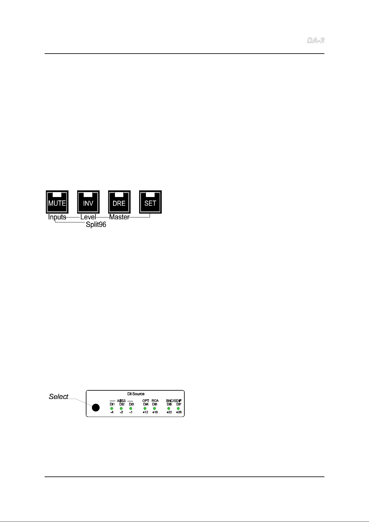
There are five control buttons. In normal use they operate in isolation to Select the digital
source, MUTE the output, INVert the output and turn on the DRE decode function. When
setting up the unit, the configuration settings - which are intended to be set and then left
alone - can be modified from one of the three 'set' modes: Set Inputs, Set Level and Set
Master. The SET button is illuminated to indicate one of these modes.
All the control settings are saved in permanent memory so that they are retained when the
unit is off.
4.1. Normal mode controls
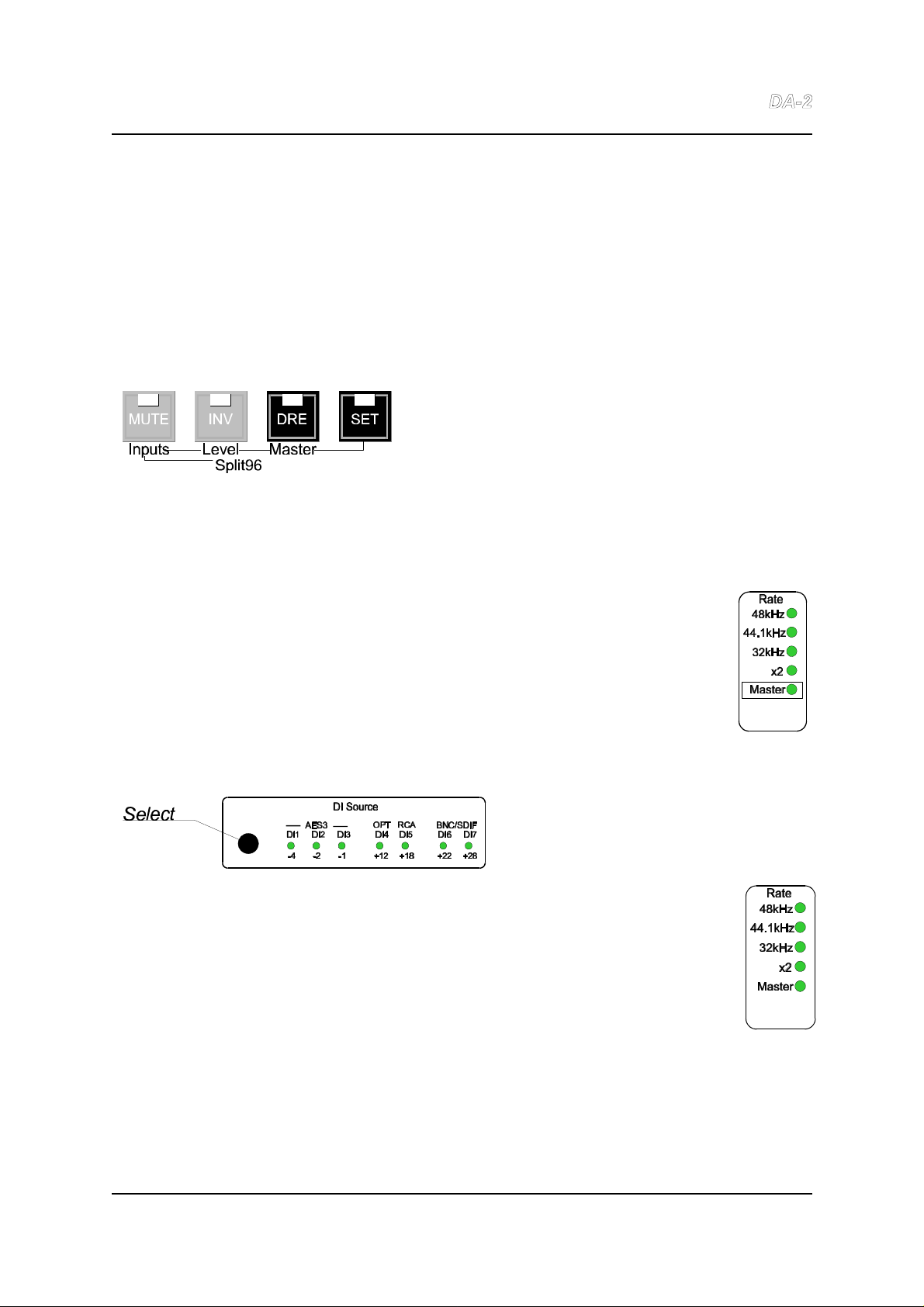
The following functions apply to the MUTE,
INV and DRE controls only if the SET
control is off. This indicates normal mode
and is the power on state.
4.1.1. MUTE
This mutes the analogue output. Digital outputs are unaffected.
4.1.2. INV
This inverts the polarity of both analogue outputs. Digital outputs are unaffected.
4.1.3. DRE
This control is used to switch on the DRE decoding function on the digital input (DRE is
described in section 3.4). Both the analogue and digital outputs are affected by this
control.
4.1.4. Select (input)
Pressing this button causes the
selected digital input to switch to
the next enabled input - see
section 4.2.
NOTE: If this control does not seem to operate correctly it may be because some inputs have been disabled.
Refer to the description of the Set Inputs control, section 4.2, to change this.
Issue 1.0 © Prism Media Products Limited
25 August 1998 Page 8 of 30
Page 9
Prism Media Products Limited Dream
Operation Manual
4.1.5. SET
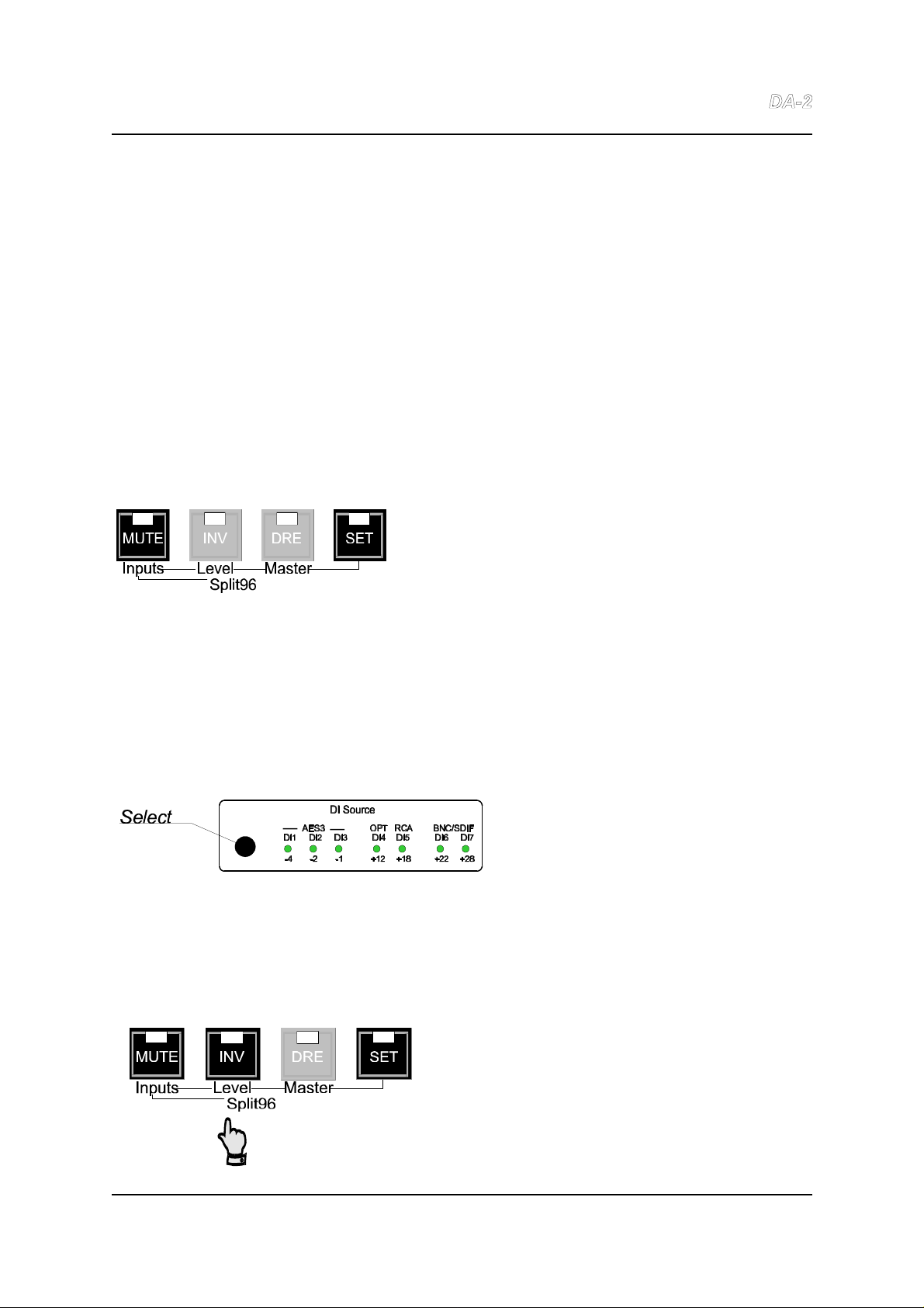
Holding this button down while pressing one of the three adjacent switches puts the unit
into one of the following control modes: Either Set Inputs, Set Level, or Set Master, as
described by the red front-panel legends. These modes allow the user to modify the
configuration of the DA-2. In normal use they are not required.
4.2. Set Inputs mode
The Set Inputs mode is used to enable or disable the selection of individual digital inputs
to avoid cycling through unused inputs when switching between sources. (Note: in this
mode the MUTE button has the function of enabling the inputs. For that reason it is
referred to as the MUTE/Inputs control.)
To enter Set Inputs mode, the DA-2 must first be
in normal mode (i.e. if the SET control is not
already illuminated). While holding the SET button
down, press the MUTE/Inputs button. This mode
is indicated by both the MUTE/Inputs and the
SET LEDs being lit.
The seven input indicators on the left of the unit illuminate to indicate the inputs that are
enabled. One (or two) of the indicators will be flickering to show the input(s) selected for
enabling or disabling. Press the MUTE/Inputs control to toggle the enable state of
this(these) input(s). The flickering will toggle between fast (mostly on), indicating enabled
and slow (mostly off) indicating disabled.
Press the Select button to cycle through
the other inputs so that they can then be
enabled or disabled using
MUTE/Inputs.
Inputs DI2 and DI3 (the second and third AES3 XLR inputs) can be configured as a
'Split96' input (see below). If configured for Split96 operation when selecting inputs for
enabling or disabling, the indicators for DI2 and DI3 will operate together.
4.2.1. Split96 Sources
Once in SET Inputs mode (see above), press
the INV/Split96 button, to change the mode of
inputs 2 and 3 for either Split96 (2-wire) or
normal (1-wire) operation.
Issue 1.0 © Prism Media Products Limited
25 August 1998 Page 9 of 30
Page 10

Prism Media Products Limited Dream
Operation Manual
In Split96 mode, two AES3 bearers both at 44.1kHz or 48kHz carry a stereo 88.2kHz- or
96kHz-sampled signal, with one channel carried on each bearer as described in ref. 8.
“Split96" or “2-wire AES” sources may only be connected to Inputs 2 & 3.
Split96 mode (for DI2 & DI3 only) is indicated once in Set Inputs mode by the INV/Split96
LED being ON. Thereafter, inputs DI2 and DI3 are treated as a Split96 pair unless the
INV/Level (Split96) button is used again to separate them - this is irrespective of the mode
expressed in the channel status.
In Split96 mode input 2 carries the left channel and input 3 carries the right channel.
Split96 mode is only available on inputs 2 & 3 and the Split96 indication does not change
while in SET Inputs mode if other inputs are selected for enabling ro disabling.
NOTE: When XLR inputs DI2 and DI3 are configured for Split96 operation, the digital XLR outputs, DO1 and DO2
are automatically set to provide Split96 output if the DA-2 is operating at 88.2kHz or 96kHz. Output channel status
in this mode is in accordance with the proposed recommendations in ref. 8.
Press SET to leave Set Inputs mode and return to normal mode.
Issue 1.0 © Prism Media Products Limited
25 August 1998 Page 10 of 30
Page 11
Prism Media Products Limited Dream
Operation Manual
4.3. Set Level mode
Set Level mode sets the maximum analogue output level for a full-scale digital input.
Range is from +5dBu to +28dBu in either 1dB steps or fine steps of 0.05dB.
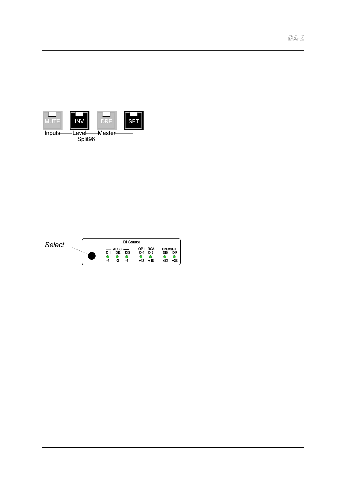
To enter Set Level mode, the DA-2 must first be in
normal mode (i.e. if the SET control is not already
illuminated). While holding the SET button down,
press the INV/Level button. Set Level mode is
indicated when both INV/Level and SET LEDs are
lit.
In this mode, the seven selector lights at the left hand side will show a pattern that relates
to the output level. The text in red under the LEDs indicates the value of each LED. The
maximum output level (in dBu) is calculated by adding the value of all the LEDs that are on.
(Remember that when connecting to an unbalanced input as described in section 3.2.5,
7.4.1 the output level will be attenuated by 6dB.)
4.3.1. Setting the maximum output level
To set the maximum output level, press
the Select button repeatedly until the
desired level is reached.
Each press will raise the level by 1dB until +28dBu, beyond which the level will return to
+5dBu.
4.3.2. Fine output level adjustment
To make a fine level adjustment hold down the INV/Level control while pressing the Select
button. Each time Select is pressed a level adjustment of -0.05dB is applied until -
0.95dB, beyond which the trim returns to zero. The trim value is not displayed. If the trim
is active, INV/Level will flash when in Set Level mode.
The fine trim can be cleared by pressing the Select button once in Set Level mode. The
INV/Level LED will then cease flashing and remain lit. Subsequent operations of Select
will apply the normal +1dB gain step for setting the maximum output level.
Note that the best dynamic range is achieved when one of the standard levels (+12, +18, +22, +28) is used and
the other LEDs (-4, -2, -1) are not illuminated. The latter LEDs show the amount of digital attenuation that has
been applied. As this attenuation lowers the maximum level but not the noise floor it reduces the dynamic range
by that amount. For example, with a level setting of +13 dBu the analogue level is set to +18dBu with a digital
attenuation of 5dBu. Therefore the dynamic range is reduced by 5dB compared with the +18dBu setting.
Issue 1.0 © Prism Media Products Limited
25 August 1998 Page 11 of 30
Page 12
Prism Media Products Limited Dream
Operation Manual
Press SET to leave Set Level mode and return to normal mode.
4.4. Set Master mode
Set Master mode is used to set the DA-2 to be clock master and change the sample rate
it uses when master. As a clock master the DA-2 requires incoming data to be
synchronized to the DA-2 internal clock. Any of the DA-2 digital outputs can be used as
a synchronization reference to the source of the data.
To enter Set Master mode, the DA-2 must first be
in normal mode (i.e. if the SET control is not
already illuminated). While holding the SET
button down, press the DRE/Master button. This
mode is indicated by both the DRE/Master and
the SET LEDs being lit.
4.4.1. Setting master or slave synchronization
In Set Master mode, pressing the DRE/Master button toggles between master
(internal) and external synchronization. This is indicated by the amber Master
light situated beneath the frequency lights at the left of the front panel. If this light
is on then the DA-2 is synchronized to a precise free-running internal oscillator;
otherwise it is synchronized externally. (If it is flashing then one of two error
states is indicated as described in section 5.4).
4.4.2. Master mode sampling rate selection
In Set Master mode, if the DA-2 is
configured as a clock master then the
sampling frequency can be changed by
pressing the Select button.
This action cycles between the available sample rates, which are displayed by
the '32kHz', '44.1kHz' and '48kHz' LEDs, and also the 'X2' LED which is used
to qualify 88.2kHz and 96kHz modes. If not configured as clock master then the
Select button has no effect. NOTE : 64kHz sampling is not supported.
Press SET to leave Set Master mode and return to normal mode.
Issue 1.0 © Prism Media Products Limited
25 August 1998 Page 12 of 30
Page 13

Prism Media Products Limited Dream
Operation Manual
5. FRONT-PANEL INDICATORS
5.1. Input selection or maximum output level setting indicators
The horizontal bank of seven green LEDs on the left side of the front panel performs three
functions:
5.1.1. Selected input indication
In Normal mode (the SET control not illuminated) one of the LEDs will be illuminated to
show the currently selected input. It will flash if that input is not present or is incorrect. On
receipt of single errors it will briefly extinguish. In certain special modes, more than one
indicator may be lit, as follows:
C Split96 (2-wire) mode for inputs 2 & 3 (see section 4.2.1 and section 7.1.2)
C SDIF-2 format using inputs 6 & 7 (see section 7.1.5)
5.1.2. Enabled inputs indication
In Set Inputs mode (the SET and Inputs controls being illuminated) the LEDs
corresponding to the enabled inputs will be illuminated. The LEDs corresponding to the
disabled inputs will be off. One LED will be flashing to indicate the input that will be
enabled or disabled if the Inputs control is pressed. (See section 4.2)
5.1.3. Peak output level indication
In Set Level mode (the SET and Level controls being illuminated) the LEDs give an
indication of the output level corresponding to peak code. This level, in dBu, is calculated
from the sum of the illuminated LEDs. (When connecting to an unbalanced input as
described in section 3.2.5, 7.4.1 the output level is 6dB less than this value.)
For example: +20dBu is shown by only the +22 and -2 LEDs being illuminated; +28dBu
is shown by only the +28 LED being illuminated. A typical consumer unbalanced level of
8dBu, which is equivalent to balanced 14dBu, needs to be indicated by the +18 and -4
LEDs being indicated.
5.2. 32kHz, 44.1kHz and 48kHz indicators
If the operating sample rate is within the capture range of the high precision PLL then one
of these indicators will indicate the sampling frequency (possibly in conjunction with the 'X2'
indicator to show 88.2kHz or 96kHz operation as described in the following section). The
appropriate indicator(s) will flash if the unit has lost the source of synchronization and
defaulted to free-run from the internal clock. If externally synchronized at a non-standard
rate, all indicators are off.
Issue 1.0 © Prism Media Products Limited
25 August 1998 Page 13 of 30
Page 14

Prism Media Products Limited Dream
Operation Manual
5.3. `X2' indicator
This LED will illuminate if the unit is synchronized to a rate between 60 and 100kHz. When
the ‘X2' indicator is lit, the D/A converter sampling-rate is double that of the normal lowerrate indicator.
5.4. `Master' indicator
The Master indicator shows several different conditions:
LED off: Sync OK
- external synchronization selected with no errors
LED flashing in time with one of the frequency indicators: No Sync
- external synchronization selected but failed
LED on: Clock master mode
- either no input or the input is correctly synchronized to the DA-2 master
LED mostly on but occasionally blinking off: Sample slipping in master mode
- each blink corresponds with a missed or repeated audio sample
Issue 1.0 © Prism Media Products Limited
25 August 1998 Page 14 of 30
Page 15

Prism Media Products Limited Dream
Operation Manual
6. CONNECTORS
6.1. Analogue output connectors
Conventional connections to a balanced analogue input should use a screened twisted
pair lead. The DA-2 output pins 2 and 3 should be wired to the two conductors of the pair
and pin 1 to the cable screen. The other end of the cable should be connected in a similar
manner with the screen connecting to the chassis of the analogue input.
The DA-2 should be connected to an unbalanced input using only pins 1 and 2 of the output
XLR. Pin 2 should connect to the signal input and pin 1 should connect to the input ground.
Using this method the signal level is half the nominal value.
NOTE: It is possible to drive unbalanced inputs from pins 2 and 3 of the DA-2 analogue output but, because the
connection has been unbalanced, this will give slightly worse performance. However, if the output is connected
in that way, it is important that pin 1 is not connected at the unbalanced input end as this will short circuit one leg
of the floating output driver.
6.2. Interconnect screens - the pin 1 conditions
'Screen' connects directly to the chassis for the digital XLR and BNC connectors. The
RCA digital coaxial connections are transformer isolated with the screen coupled to the
chassis using a capacitor at the connector. The analogue output screens are the mid
points of the floating differential outputs. They are coupled to the chassis using a capacitor
from pin 1 to the chassis.
Issue 1.0 © Prism Media Products Limited
25 August 1998 Page 15 of 30
Page 16
Prism Media Products Limited Dream
Operation Manual
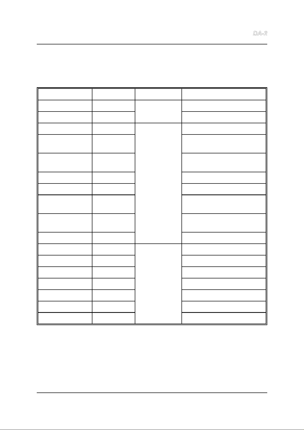
6.3. Connector table
Viewed from the rear the connectors are as follows:
Left Hand Side IEC320 Mains power inlet
XLR-Male Analogue Analogue out left/A
XLR-Male Outputs Analogue out right/B
XLR-Female DI1 - AES3
XLR-Female DI2 - AES3 (Left channel for
Split96, 2-wire 96kHz)
XLR-Female DI3 - AES3 (Right channel
for Split96, 2-wire 96kHz)
OPTICAL Digital DI4 - IEC958 optical
RCA-phono Inputs DI5 - IEC958 coaxial
BNC-75S DI6 - AES-3ID or
L - SDIF-2 input left/A
BNC-75S DI7 - AES-31D or
R - SDIF-2 input right/B
BNC-75S WCK - Word-clock input
BNC-75S L - SDIF-2 output left/A
BNC-75S R - SDIF-2 output right/B
BNC-75S Digital WCK - Word-clock output
RCA-phono Outputs IEC958 consumer format
OPTICAL IEC958 consumer format
XLR-Male DO1 - AES3 output 1
Right Hand Side XLR-Male DO2 - AES3 output 2
XLR wiring conventions for both analogue and digital connections are:
pin 1 Screen
pin 2 Balanced input or output (Hot or `+')
pin 3 Balanced input or output (Cold or `-')
Issue 1.0 © Prism Media Products Limited
25 August 1998 Page 16 of 30
Page 17

Prism Media Products Limited Dream
Operation Manual
7. SPECIFICATION
The following specification, offered in good faith, is subject to change without notice.
Errors and omissions excepted.
7.1. Digital Inputs
All inputs can handle sources with sampling rates from 32kHz to 96kHz. Some inputs have
special functions such as inputs 2 & 3 (Split96 or 2-wire mode) and inputs 6 & 7 (AES3-ID
or SDIF-2).
7.1.1. General (except SDIF-2)
Jitter Tolerance
Above 12kHz: 0.5UI (This is 88.6ns at fs = 44.1kHz)
50Hz to 12kHz: Increases with falling jitter frequency.
e.g: 0.75 UI at 8kHz
30 UI at 200Hz
Below 50Hz: > 128UI (22.7 us at fs = 44.1kHz)
Note: Jitter tolerance is a measure of the ability of a receiver to correctly decode a digital interface signal which
has jitter. Like most other jitter parameters it is normally measured in 'unit intervals'. A unit interval (UI)
corresponds to the smallest nominal time interval in the interface signal, for the AES3 or IEC958 interface formats
there are 128 unit intervals per sample. Therefore at a sample frequency of 44.1kHz the unit interval is 177 ns.
References 5 and 6 explain interface jitter in more detail.
Digital Input Resolution/Word-Length: 24 bits
The Dream resolves all the data bits of the digital interface formats. Input signals
are not truncated and hence truncation distortion does not occur. For example: a sine
wave modulating only the lowest 4 bits of the 24-bit interface signal is reproduced at the
correct amplitude.
Note that, in conformance with the digital audio interface specifications, all signals with consumer channel status
and a Category Code indicating a 16-bit or 20-bit device, and signals with professional channel status that
indicate that the auxiliary audio data bits do not carry the main audio signal, will have the lower 4 bits masked off
to avoid non-audio data adding to the audio. The SDIF-2 format is also limited to a maximum resolution of 20-bits
for the audio data.
7.1.2. Balanced AES-3 XLR inputs: DI1, DI2, DI3
Input impedance: 110S.
These conform with the professional interface, AES3-1992 [Ref. 1], with transformers for
improved isolation. However if the data is encoded according to the consumer format of
IEC958 [Ref. 4] it is also decoded correctly.
Issue 1.0 © Prism Media Products Limited
25 August 1998 Page 17 of 30
Page 18

Prism Media Products Limited Dream
Operation Manual
Pin 1 of the XLR connector is connected to the chassis via a capacitor and the signal is
presented differentially across pins 2 and 3.
NOTE: XLR inputs 2 and 3 may be jointly configured as a 'Split96' input, allowing stereo
88.2kHz- and 96kHz-sampled inputs with one channel on each bearer. This format is
described in ref. 8.
7.1.3. Optical input: DI4
This input is physically compatible with the Toshiba `TosLink' fibre-optic connector, and
data encoded according to professional (AES3-1992) or consumer (IEC958) formats is
correctly decoded.
7.1.4. Coaxial (RCA) consumer input: DI5
Input impedance: 75S.
This conforms to the coaxial specification of IEC958 and, for improved isolation, has
transformer isolation with the screen capacitatively coupled to the chassis. Data encoded
according to professional (AES3-1992) or consumer (IEC958) formats is correctly
decoded.
7.1.5. Dual-function coaxial (BNC) professional inputs: DI6, DI7
Input impedance: 75S.
The connectors either operate as coaxial AES3 (AES-3ID) or SDIF-2 inputs. An auto-
detection algorithm decides which format to use as follows.
If the unit is in clock master mode (Master light on):
If a valid SDIF signal is detected on the selected input then both inputs will be
treated as SDIF-2 format.
If a valid AES or IEC958 signal is detected on the selected input then that input will
be decoded as that format.
Otherwise, if the unit is not in clock master mode (Master light off):
If a valid word clock signal is present on the WCK input then both inputs will be
treated as SDIF-2 format. Without a valid WCK then any signal on the selected
input will be treated as AES3 or IEC958 format.
Issue 1.0 © Prism Media Products Limited
25 August 1998 Page 18 of 30
Page 19

Prism Media Products Limited Dream
Operation Manual
7.1.5.1. DI6, DI7 operating as AES3 or IEC958 format inputs.
These conform to the AES-3ID recommendation [Ref. 7]. However data encoded
according to professional (AES3-1992) or consumer (IEC958) formats is correctly
decoded.
7.1.5.2. DI6, DI7 operating as SDIF-2 (Sony) format inputs
The input selection indicators for DI6 and DI7 both illuminate if the inputs are being handled
in this format. (If one of the inputs is not present then that indicator will flash.)
In this mode the inputs conform with the interfaces initially used by the Sony
PCM-1610/1630 PCM encoder. The signal on DI6 is the left channel and on DI7 is the
right channel.
Note: Signals in this format are D.C. coupled at TTL levels and transmitted most significant bit (MSB) first in nonreturn to zero (NRZ) format. A synchronization pattern identifies the start of a new sample word. Some
implementations of this interface do not use the synchronization pattern to identify the sample word boundary.
Such equipment will often require delays to be carefully matched before they will work correctly. The Dream
uses a rugged algorithm to correctly decode SDIF data independent of delays or phase.
7.1.6. Coaxial word-clock (WCK) input
This input can be used to lock the DA-2 to a sample rate square wave, or word-clock. It
is used in conjunction with the SDIF-2 inputs to synchronize the Dream internal clock
to the SDIF-2 source equipment.
Input impedance: 75S
Input level: 200mV to 10V pk-pk
Mark-space ratio: 40:60 to 60:40
Sync reference point: Rising edge
This input is ac coupled so that in addition to operation with the TTL levels typical of SDIF2 word clock sources it will also work with lower signal levels, such as from a double or
triple terminated source, with an optimum noise margin.
Note: When using WCK synchronization the digital outputs of the Dream are timed so that the start of the
sample frame is coincident with the timing reference point (the rising edge of WCK). Specified delay
measurements are also made from the timing reference point. This input is not required if the Dream is
configured as clock master.
Issue 1.0 © Prism Media Products Limited
25 August 1998 Page 19 of 30
Page 20

Prism Media Products Limited Dream
Operation Manual
7.2. Synchronization
The Dream has two methods of synchronization. In almost all applications the
device will operate as a clock slave so that it derives its internal clocks from the incoming
digital audio signal. It can also be operated as a clock master (see section 12). In that
case care must be taken to ensure that the digital source supplying the input signals is
`locked', or synchronized, to the DA-2.
7.2.1. Clock slave synchronization
The Dream will normally be used synchronized with an external clock source. In this
slave configuration the internal clocks will be derived from the input signal (or, in the case
of SDIF-2, from the WCK input). The Dream can operate as a slave if the incoming
sample frequency is within one of the capture ranges of the high precision clock. If the
external clock is not within one of the high precision ranges, then the DA-2 can also
operate as a slave, but without the same jitter attenuation performance, over the 30kHz 50kHz and 60kHz - 100kHz ranges.
High precision clock capture range: ±0.15%
Nominal Minimum Range
32 kHz 31.96 to 32.04kHz
44.1 kHz 44.03 to 44.17kHz
48 kHz 47.93 to 48.07kHz
64kHz 54.40 to 73.60kHz
88.2 kHz 88.06 to 88.34kHz
96 kHz 95.86 to 96.14kHz
Normal low-rate clock capture range : 40kHz ±25%
Non-std: 30.0 - 50.0kHz
Normal high-rate clock capture range : 80kHz ±25%
Non-std: 60.0 - 100.0kHz
Lock-up time:
Signal present on output 0.1 s
High precision PLL locked 2 s
Digital input to digital output timing difference: < 1% of sample period
Note: This is referred to the first transition of an AES3 or IEC958 frame or the rising edge of word clock.
Issue 1.0 © Prism Media Products Limited
25 August 1998 Page 20 of 30
Page 21

Prism Media Products Limited Dream
Operation Manual
7.2.2. Clock master synchronization
Clock accuracy: ±10 ppm
Reference to input timing variation, from ideal, before sample slip:
±75% of sample period
Sample slip hysteresis: 50% of sample period
Note: The AES11-1991 synchronization standard [2] requires an input synchronization window of ±25% of a
sample period without hysteresis. The Dream exceeds this specification. This is to allow it to work properly
with equipment that does not conform with the AES11 standard. This hysteresis avoids the possibility of repeated
sample slips which can occur as a result of small timing variations about some static offset.
7.3. Digital Outputs
The digital outputs provide the same audio data as present on the selected digital input,
except when DRE decode is active. The output channel status data is not copied from the
input but is regenerated by translating from the input format to the output format. This
means that the various output connectors always have the appropriate data format for the
connector style.
NOTE: The input format is determined by the data content at the input, and not the connector. Therefore when
connecting an AES3 data format, but consumer (SPDIF) electrical format signal to the RCA coaxial input then the
signal channel status format will be translated to consumer format at the RCA coaxial output and remain in
professional format at the XLR output. This means that the Dream is also a digital audio format converter
and corrector.
7.3.1. Jitter characteristics common to all digital outputs
Jitter peaking: less than 1dB in both ranges
High precision clock:
Jitter attenuation slope: 80dB per decade
Corner frequency: approx 80Hz
Attenuation above 500Hz: > 60dB
Wide range clock:
Jitter attenuation slope: 40dB per decade
Corner frequency: approx 2 kHz
Attenuation above 8kHz: > 24dB
Intrinsic jitter: < 0.005 UI pk-pk (< 1ns at fs = 44.1kHz)
Note: Intrinsic jitter is measured using a low frequency cut-off of 200Hz, see references 5 and 6 for a more
detailed explanation of these interface jitter parameters.
Issue 1.0 © Prism Media Products Limited
25 August 1998 Page 21 of 30
Page 22

Prism Media Products Limited Dream
Operation Manual
7.3.2. Audio data on digital outputs
Unless the DRE decoder function is operating, all the audio data on the input is passed
through to the digital outputs without modification. However the SDIF-2 output is limited
to a maximum of 20-bits.
If the DRE decoder function is on then the digital output word length is 18 bits.
Note: To avoid truncation distortion care must always be taken to match the signal word length to the input word
length of following equipment. If the DA-2 is passing through 24-bit data then truncation distortion will occur in
the signal at the SDIF-2 outputs. Often equipment is limited to a 16-bit input resolution and further truncation will
occur at that equipment if the signal is not re-dithered. This can be done by setting the output word-length of the
source device appropriately or by using a proprietary re-dither or noise-shaping device. (For example, the Prism
Sound SNS-4 Super Noise Shaper, or the Prism Sound Dream AD-2 or AD-124. The latter are analogue-to-digital
converters which can also operate as re-ditherers or noise-shapers when fed with a digital source.)
7.3.3. Balanced AES3 (AES/EBU) professional format: DO1 and DO2
These conform with the professional interface, AES3-1992, with transformers for improved
isolation.
Pin 1 of the XLR connector is connected to the chassis and the signal is output
differentially across pins 2 and 3.
Output impedance: 110 S ± 20%
Output level: 4 V ± 10% (terminated)
Rise/fall time: 20 ns ± 20% (terminated)
A professional channel status pattern is generated for these outputs, carrying the emphasis
and word-length information transcoded from the input and other appropriate information
dependent on sample frequency or operating mode.
NOTE: When the XLR inputs DI2 and DI3 are configured for Split96 operation, the digital
XLR outputs, DO1 and DO2 are also automatically configured to provide Split96 output
whenever the DA-2 is operating at 88.2kHz or 96kHz. Output channel status in this mode
is in accordance with the proposed recommendations in ref. 8.
Valid and user-data bits are passed through from the selected digital input (not present in
SDIF-2). Reception errors are indicated by setting the validity flag.
Issue 1.0 © Prism Media Products Limited
25 August 1998 Page 22 of 30
Page 23

Prism Media Products Limited Dream
Operation Manual
7.3.4. Optical consumer format
This output is physically compatible with the Toshiba `TosLink' fibre-optic connector.
If the selected input carries consumer format channel status, and the unit is not set to clock
master mode then that status is passed through. Otherwise a consumer channel status
pattern is generated, carrying the emphasis information transcoded from the input.
Note: In IEC958 there is no category code for DAC so with a non-consumer status input the category code
transmitted in the consumer channel status output is set to `ADC'.
Valid and user-data bits are passed through from the selected digital input (not present in
SDIF-2). Reception errors are indicated by setting the validity flag.
7.3.5. Coaxial consumer format (IEC958)
This conforms with the unbalanced interface defined in IEC958 clause 5.3 and carries
consumer format channels status information as defined in IEC958 clause 4.4.2. This
output is floating with the screen capacitatively coupled to the chassis.
Output impedance: 75 S ± 10%
Output level: 0.5 V ± 10% (terminated)
Rise/fall time: 22 ns ± 20% (terminated)
The data carried on this output is identical to the data on the optical consumer format
output (see above).
7.3.6. Coaxial SDIF-2 (Sony) format, L and R.
These outputs conform with the interfaces initially used by the Sony PCM-1610/1630 PC M
encoder and often called SDIF-2. Signals in this format are at TTL levels and transmitted
most significant bit (MSB) first in non-return to zero (NRZ) format. A synchronization
pattern identifies the start of a new sample word.
Output impedance: approximately 30 S
Load impedance: 75 S
Output level: 2.8 V ± 0.5 V (when terminated in 75 S)
Rise/fall time: 60 ns
The embedded flags carried on the SDIF-2 outputs are set as follows:
C Emphasis: Set if CD (15/50µs) emphasis is indicated on the selected input.
C Dub prohibit: Always clear.
7.3.7. Coaxial SDIF-2 (Sony) word-clock format
Issue 1.0 © Prism Media Products Limited
25 August 1998 Page 23 of 30
Page 24

Prism Media Products Limited Dream
Operation Manual
This output carries a TTL level square wave at the sample rate. The rising edge coincides
with the start of a sample frame on the digital outputs.
Electrically it is identical to the SDIF-2 L and R outputs.
This output is normally used to synchronize equipment that is using the SDIF-2 data
outputs, but may also be used to synchronize any equipment which will accept a Wordclock
ref sync.
7.4. Analogue Outputs
The analogue outputs are on a three pin XLR connector with positive and negative signal
polarities on pins 2 and 3 respectively, and the mid-point on pin 1. These pins float
together with respect to the chassis earth. This high common mode impedance means
that the pin 1 screen connection to following equipment will eliminate any common mode
component on the output without introducing significant cable screen currents.
7.4.1. Connecting the DA-2 to unbalanced inputs
For optimum performance the DA-2 should be connected to an unbalanced input using
only pins 1 and 2. Pin 2 should connect to the signal conductor and pin 1 should connect
to the ground or return. The signal level is then halved.
NOTE : Use of output pin 3 instead of 2 will result in phase inversion.
[It is possible to drive unbalanced inputs from pins 2 and 3 but this unbalances the
output and can lead to hum. In any case do not connect any of the three output pins to
each other].
Differential output impedance: 47 S ± 1 S (pin 2 to pin 3)
Single-ended output impedance: 24 S ± 1 S (pin 1 to 2 or 3)
Coupling impedance to chassis: 4.7 kS (chassis to pin 1,2 or 3)
Common-mode range: 70 V
Issue 1.0 © Prism Media Products Limited
25 August 1998 Page 24 of 30
Page 25

Prism Media Products Limited Dream
Operation Manual
7.5. Performance Specification
Specifications quoted in this section are to AES17-1991 (ANSI S4.51-1991) [Ref. 3], at
48kHz with output level set to +22dBu (for digital full scale input) except where stated.
Frequency response:
Pass band:
fs = 48kHz: 5 Hz - 20 kHz ± 0.05 dB
0.1Hz - 21.7kHz - 3dB
fs = 44.1kHz:5 Hz - 20 kHz ± 0.05 dB
0.1Hz - 20.8kHz - 3dB
fs = 32kHz: 5 Hz - 14.5 kHz ± 0.05 dB
0.1Hz - 15kHz - 3dB
fs = 96kHz: 5 Hz - 35 kHz ± 0.05 dB
0.1Hz - 40kHz - 3dB
fs = 88.2kHz:5 Hz - 31.7 kHz ± 0.05 dB
0.1Hz - 37kHz - 3dB
Note: relaxed roll-off filters are deliberately specified for 88.2kHz and 96kHz
operation to minimize audio-band time-domain dispersion effects - 'pre- and
post-echoes'.
Stop band:
Begins at fs/2 for all sampling rates
Group delay:
fs = 96 kHz 34.5 samples 0.36 ms
fs = 88.2 kHz 37 samples 0.42 ms
fs = 48 kHz 61.5 samples 1.28 ms
fs = 44.1 kHz63.3 samples 1.44 ms
fs = 32 kHz 63.3 samples 1.98 ms
Phase linearity error < 0.8E within the following frequency ranges:
5 Hz - 22kHz (fs = 96 kHz)
5 Hz - 20kHz (fs = 88.2 kHz)
5 Hz - 20kHz (fs = 48 kHz)
5 Hz - 18kHz (fs = 44.1 kHz) (1.6E over 2.5 Hz - 20 kHz)
5 Hz - 15kHz (fs = 32 kHz)
Inter-channel phase deviation
without de-emphasis < 0.5E
with de-emphasis < 0.5E
Issue 1.0 © Prism Media Products Limited
25 August 1998 Page 25 of 30
Page 26

Prism Media Products Limited Dream
Operation Manual
Absolute phase: Correct unless Invert function on.
Note: Unless invert is on negative digital inputs produce a negative analogue output. This makes the pin 2 of
the output connector negative with respect to pin 3. This is in accordance with the standards IEC26812(1969) and AES14.
Crosstalk: <-100 dB (20 Hz to 20 kHz)
Sampling jitter rejection:
High precision clock (used if clock within 0.15% of standard frequencies).
Jitter attenuation slope: 80dB per decade
Corner frequency: approx 80Hz
Attenuation above 500Hz: > 60dB
Wide range clock (used if clock outside normal frequency tolerances):
Jitter attenuation slope: 40dB per decade
Corner frequency: approx 800 Hz
Attenuation above 8kHz: > 30dB
Maximum output signal level:
Gain is adjustable so that the output level for 0dB FS (full scale) input can be
preset from +5 dBu to +28 dBu in 1dB steps with fine trim in steps of 0.05dB. At
sample rates below 44kHz the maximum level is +25dBu.
This is made up from four analogue gain settings (corresponding to +12 dBu, +18 dBu, +22 dBu, +28 dBu)
and a variable attenuation in the digital domain. As the digital attenuator reduces the maximum level without
lowering the noise floor it has the effect of lowering the dynamic range. For optimum dynamic range the
digital attenuation should be minimised. The digital attenuation is inactive at level settings of +12 dBu, +18
dBu, +22 dBu and +28 dBu. (For samples rates below 44kHz the four analogue gain settings are 3dB lower
so the digital attenuation is inactive at settings of +9dBu, +15dBu, +19dBu and +25dBu. However the final
gain is shown correctly unless the gain is set to more than the maximum of +25dBu)
Gain error: < 0.05 dB for all settings
Gain trim step size: 0.05 dB
Level-dependent logarithmic gain linearity: << 3dB at -144dB FS
Note: This is a measurement of the output level of a 996.115Hz tone with respect to the input level. The output
level at 997Hz is measured using 32 averages of an 8192 point FFT with a rectangular window. This method
has much higher resolution than the test in AES17, which specifies a third-octave band-pass filter to eliminate
noise. Even so, the signal level measurements are still dominated by the noise floor at -144dB FS.
Issue 1.0 © Prism Media Products Limited
25 August 1998 Page 26 of 30
Page 27

Prism Media Products Limited Dream
Operation Manual
Harmonic distortion and noise <-104dB (997 Hz at -1dB FS)
Intermodulation distortion <-90dB
Note: The intermodulation test from AES17 uses 18kHz and 20kHz signals at -6.03dB FS each. The result is
the ratio of the total output rms signal level to the rms sum of the 2nd and 3rd order modulation products at
2kHz and 16kHz.
Dynamic range or signal to noise ratio:
>111dB CCIR-RMS
>114dB (A weighted RMS)
>111dB (unweighted RMS)
Note: Measured at output settings of +18,+22 and +28dBu at a level of -60 dB FS.
Idle channel noise: <-111dB FS CCIR-RMS
<-114dB FS (A weighted RMS)
<-111dB FS (unweighted RMS)
Note: Measured at output settings of +18,+22 and +28dBu
All Spurious levels: <-110dBFS full scale signals
<-125dBFS signals below -20dBFS
<-131dBFS signals below -60dBFS
Note: Highest level of any spurious frequency component, including harmonic components
Aharmonic spurious levels:<-125dBFS full scale signals
Note: Highest level of any spurious frequency component, excluding harmonic components
7.6. Power
7.6.1. Mains voltage: Internally set for 90-120V (nominally 110V) or 195250V (nominally 230V) operation. The supply
voltage is indicated on the rear panel.
7.6.2. Consumption: 30W
7.7. Physical Dimensions
Weight: 8.8 lb (4 Kg)
Width: 19 inch (483mm) (rack-mountable)
Height: 1U (44mm)
Depth: 10.25 inches (260mm)
Issue 1.0 © Prism Media Products Limited
25 August 1998 Page 27 of 30
Page 28
Prism Media Products Limited Dream
Operation Manual
8. INTERNAL CONFIGURATION OPTIONS AND FUSES
Other than the external mains fuse, the following parts can only be accessed by
removing the equipment top cover. This should only be undertaken by qualified
personnel. There are no user serviceable parts inside this unit.
8.1. Fuses
There is one mains fuse in the IEC320 mains inlet. If this fuse is blown it should be
replaced by a similar value and type. (20x5mm 250V 2AT anti-surge)
There are seven fuses internal to the unit. If these fuses have blown a fault has occurred
and the unit should be returned to the manufacturer or agent for service. The fuse types
and application are:
F1 - Digital processing, input and output
Type: 2AT Wickman TR5 subminiature type no. 19372K/2A
F5,F6,F7,F9 - Analogue output channel A
F2,F3,F4,F8 - Analogue output channel B
Type: 0.5AT Wickman TR5 subminiature type no. 19372K/500mA
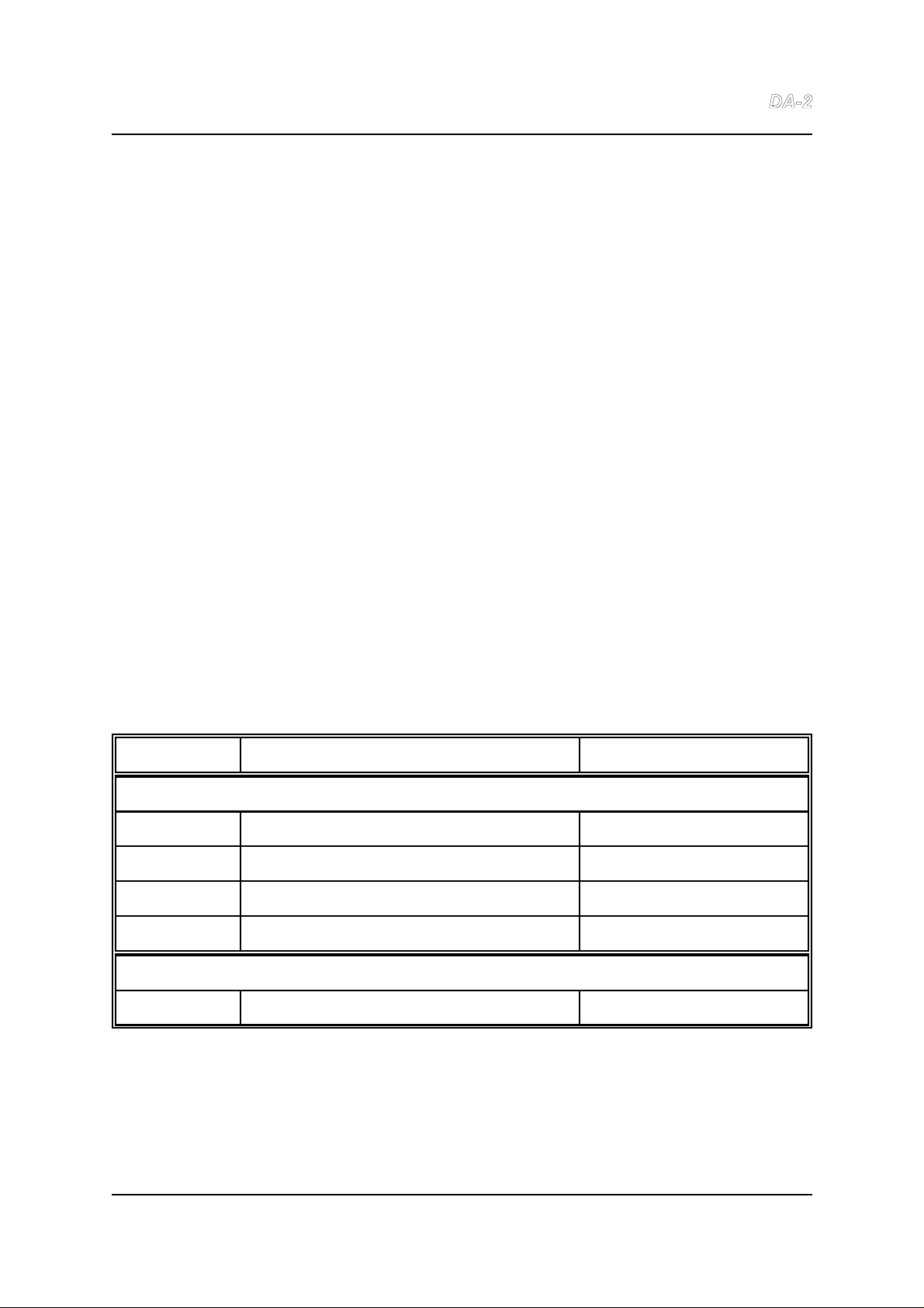
8.2. PCB jumper links
Link Purpose Factory setting
Main board (PREV051/1)
LK1 (Option select - not used) No links fitted
LK2 Do not fit Not fitted
LK3 Do not fit Not fitted
CN4 Future compatibility Link pins 15-16, 17-18
Sub Board (PREV047/3)
LK1 (Option select - not used) Not fitted
Issue 1.0 © Prism Media Products Limited
25 August 1998 Page 28 of 30
Page 29

Prism Media Products Limited Dream
Operation Manual
8.3. Mains transformer voltage selection
The mains transformer has a tapped primary to allow operation at nominal voltages of
230V or 110V. The brown lead is connected to the lower terminal on the mains inlet.
The upper terminal is connected as follows:
110V Connect red primary lead to the upper terminal of mains inlet.
230V Connect orange primary lead to the upper terminal of mains inlet.
The unused primary lead terminal should be firmly secured to the other primary leads.
If the mains operating voltage has been changed then the rear panel label should be
changed to reflect this.
9. ELECTROMAGNETIC COMPATIBILITY
This equipment is intended for use in an electromagnetically controlled environment. To
maintain the performance specification it should not be subject to strong magnetic
fields (such as in the immediate vicinity of a power amplifier or cathode ray tube) and all
connections should be terminated as described below. This is also required to ensure
that emissions are within applicable norms and that it does not interfere with other
equipment.
All coaxial connections should be made using a properly screened 75S cable with the
screen connected to the outer of the connector at both ends. All XLR connections
should use a screened twisted pair cable with the screen connected to pin 1 of the XLR
connector at both ends. In the case of the digital XLR connections this cable should be
of 110S impedance.
Issue 1.0 © Prism Media Products Limited
25 August 1998 Page 29 of 30
Page 30

Prism Media Products Limited Dream
Operation Manual
10. REFERENCES
[1] AES3-1992 - ` Recommended Practice for Digital Audio Engineering - Serial Transmission Format for Two-Channel
[2] AES11-1991 - `AES Recommended Practice for Digital Audio Engineering - Synchronization of Digital Audio
[3] AES17-1991 - `AES Standard Method for Digital Audio Engineering - Measurement of Digital Audio Equipment' J.
[4] IEC958 - `Digital Audio Interface' International Electrotechnical Commission 1989
[5] Julian Dunn, Barry McKibben, Roger Taylor and Chris Travis - `Towards Common Specifications for Digital Audio
[6] Julian Dunn and Ian Dennis - `The Diagnosis and Solution of Jitter-Related Problems in Digital Audio Systems'
[7] AES-3id-1995 - `AES information document for digital audio engineering - Transmission of AES3 formatted data by
[8] Draft AES3-1992 Amendment 3-xxxx - Serial Transmission Format for Two-Channel Linearly Represented Digital
Linearly Represented Digital Audio Data' J. Audio Eng. Soc., Vol 40 No. 3, pp 147-165 (June 1992)
Equipment in Studio Operations' J. Audio Eng. Soc., Vol. 39 No. 3, pp 155-162 (March 1991)
Audio Eng. Soc., Vol. 39 No. 12, pp 961-975 (December 1991)
Interface Jitter' Preprint 3705, presented at the 95th AES Convention, New York, October 1993
Preprint 3868, presented at the 96th AES Convention, Amsterdam, February 1994.
unbalanced coaxial cable' J. Audio Eng. Soc., Vol. 43 No. 10, pp 827-844 (October 1995)
Audio Data' (still in preparation, July 1998)
FURTHER INFORMATION
Enquiries about this product should be addressed to :
Prism Media Products Limited
William James House
Cowley Road
Cambridge
CB4 4WX
UK
Phone: +44-(0)1223-424988
Fax: +44-(0)1223-425023
Email: [email protected]
Web: http://www.prismsound.com
Issue 1.0 © Prism Media Products Limited
25 August 1998 Page 30 of 30
Page 31

Prism Media Products Limited
William James House
Cowley Road
Cambridge
CB4 0WX UK
E-mail : [email protected]
Web : www.prismsound.com
Tel: +44 (0)1223 424988
Fax: +44 (0)1223 425023
 Loading...