

Page 1

Dual-rate A/D converter
with
Super Noise Shaping
and synchronous
Sample-Rate Conversion (SRC)
Operation Manual
Issue 0.2 11 August 1998
Page 2

Prism Media Products Limited AD-2 Dual-rate A/D converter
Operation Manual
CONTENTS
1. INTRODUCTION ..............................................4
1.1. Notational conventions ....................................4
1.2. Terminology for high-sampling rate interfaces ..................5
2. GETTING STARTED ...........................................6
2.1. Unpacking your AD-2 Dual-rate A/D converter ..................6
2.2. Using the AD-2 for the first time .............................6
2.3. A-D mode Factory Presets .................................8
2.4. D-D mode Factory Presets ................................10
2.5. Selecting one of the Factory Preset configurations ..............11
2.6. Check the analogue line-up (headroom) ......................11
2.7. Synchronization .........................................12
2.8. Introduction to the Setup Wizard ............................13
3. FREQUENTLY-ASKED QUESTIONS (FAQs) .......................15
3.1. What do the flashing !!! Characters mean in the display? .........15
3.2. Can I assign the Aux output to one of the XLR connectors? ......15
3.3. How can I enable headroom setting by the stores? .............15
3.4. Can I drive 2 wire and 1-wire 96kHz at the same time? ..........16
3.5. How do I do sample-rate conversion? ........................16
3.6. Can the AD-2 convert up to 96kHz from 44.1kHz? ..............17
3.7. How do I change the synchronization to AES3? ................17
3.8. What is DRE? ..........................................17
4. OPERATION REFERENCE .....................................18
4.1. General configuration rules ................................18
4.2. To reset the AD-2 to its factory default state ...................19
4.3. Setup Wizard ..........................................19
4.4. Program level meter .....................................20
4.5. Store Controls ..........................................21
4.6. Menu system operation ...................................26
4.7. Menu system reference ...................................29
4.8. System State Indicator LEDs ..............................30
5. SYNCHRONIZATION MODES ..................................33
6. CONNECTORS ..............................................35
6.1. Analogue input connectors ................................35
6.2. Digital input connectors ...................................35
6.3. Digital output connectors ..................................36
6.4. Interconnect screens - the pin 1 conditions ....................36
6.5. Connector table .........................................38
Issue 0.2 © Prism Media Products Limited
11 August 1998 Page 2 of 58
Page 3

Prism Media Products Limited AD-2 Dual-rate A/D converter
Operation Manual
7. TECHNICAL SPECIFICATION ..................................39
7.1. A-D mode Performance Specification ........................39
7.2. Analogue Inputs ........................................41
7.3. D-D mode Performance Specification ........................42
7.4. Digital Inputs ...........................................43
7.5. Digital Outputs ..........................................46
7.6. Synchronization .........................................49
7.7. Power ................................................50
7.8. Physical Dimensions .....................................50
7.9. Fuses ................................................50
8. PERFORMANCE PLOTS ......................................52
8.1. Dynamic Range .........................................52
8.2. THD+n ................................................53
8.3. SRC (Sample-rate converter) ..............................54
9. SNS NOISE SHAPER CHARACTERISTICS ........................55
10. ELECTROMAGNETIC COMPATIBILITY ...........................57
11. REFERENCES ..............................................58
Manual Revision History
Issue 0.1 31 July 1998 ; Original issue
Issue 0.2 11 August 1998 ; Document formatting changes only
Product Revision History
Software revision 1.0x 31 July
1998
Prism Media Products Limited
William James House
Cowley Road
Cambridge
CB4 0WX
UK
Phone: +44-(0)1223-424988
Fax: +44-(0)1223-425023
Email : [email protected]
Web: http:\\www.prismsound.com
Issue 0.2 © Prism Media Products Limited
11 August 1998 Page 3 of 58
Page 4

Prism Media Products Limited AD-2 Dual-rate A/D converter
Operation Manual
1. INTRODUCTION
To get started immediately, please turn to page 6.
The AD-2 Dual-rate A/D converter is intended for professional audio use in
applications where a very high level of performance is required. The high performance
of the AD-2 was a key design objective and care should be taken when making
comparisons to check that consistent measurement units and methods are employed.
In this manual, all specifications and measurement results are obtained using the
methods of AES17 unless otherwise stated.
The AD-2 can perform a number of tasks:
" analogue to digital conversion, available on two separate outputs which may
operate at different sampling rates and wordlengths and on a variety of output
formats
" digital sampling rate conversion such as from 96kHz to 44.1kHz
" digital format conversion
- between various I/O formats such as AES3/SDIF-2 et. al.
- between “one-wire” and “two-wire” formats for high sampling rates
" digital processing such as wordlength reduction & noise shaping
(e.g. for 16-bit CD)
" synchronization of disparate formats such as locking a 96kHz audio recording
chain to a 48kHz or 44.1kHz wordclock
1.1. Notational conventions
In this manual the following notational conventions are used for clarity:
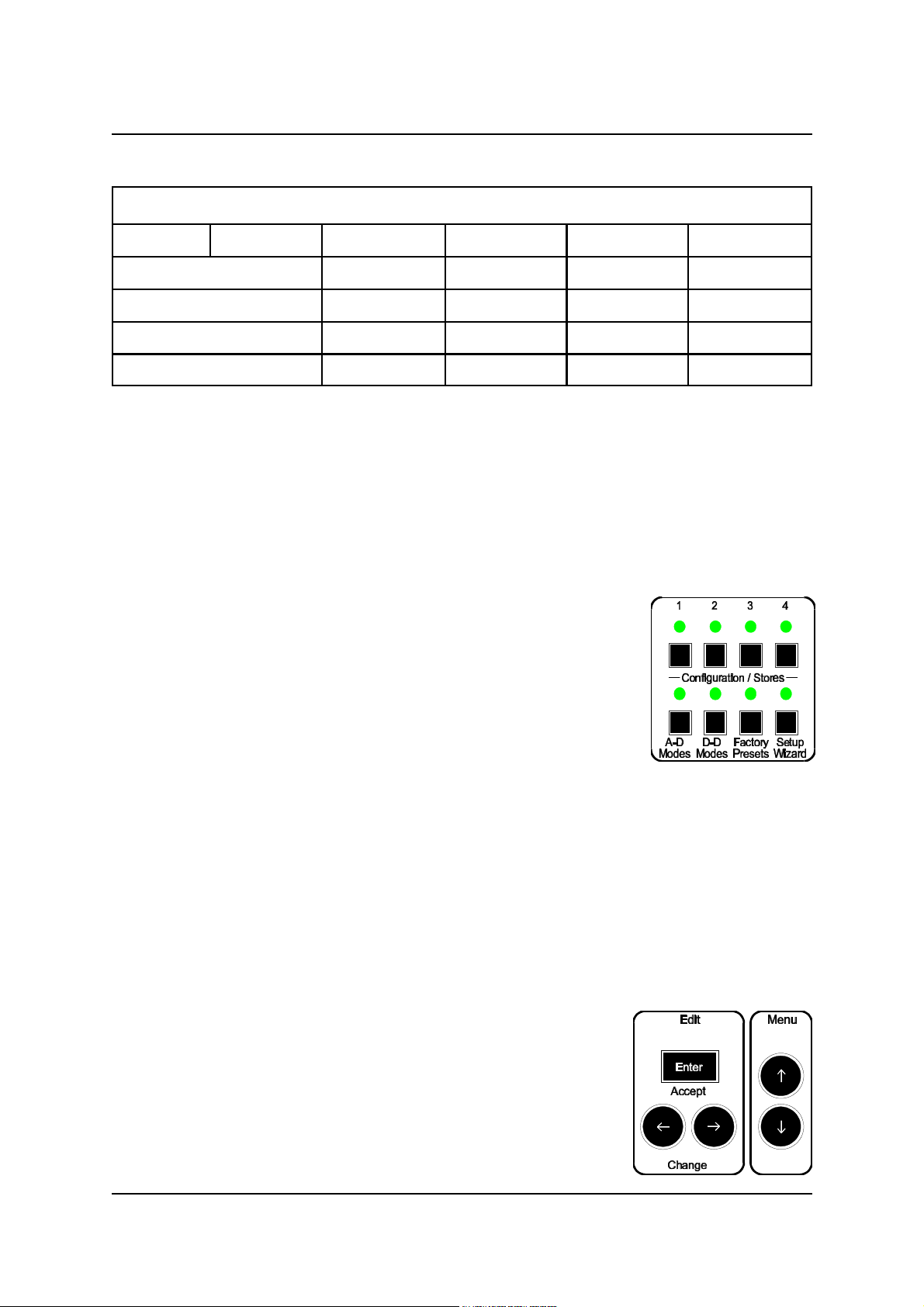
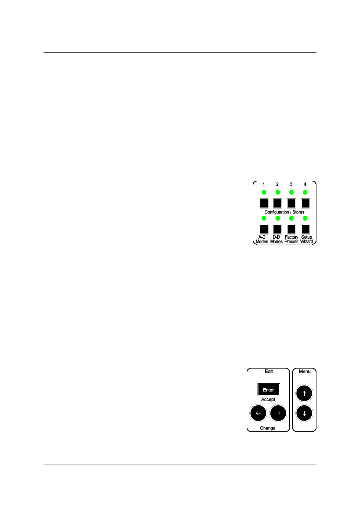
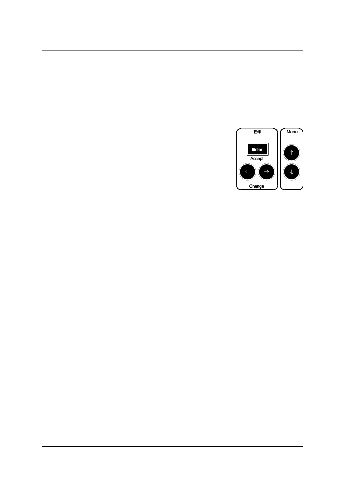
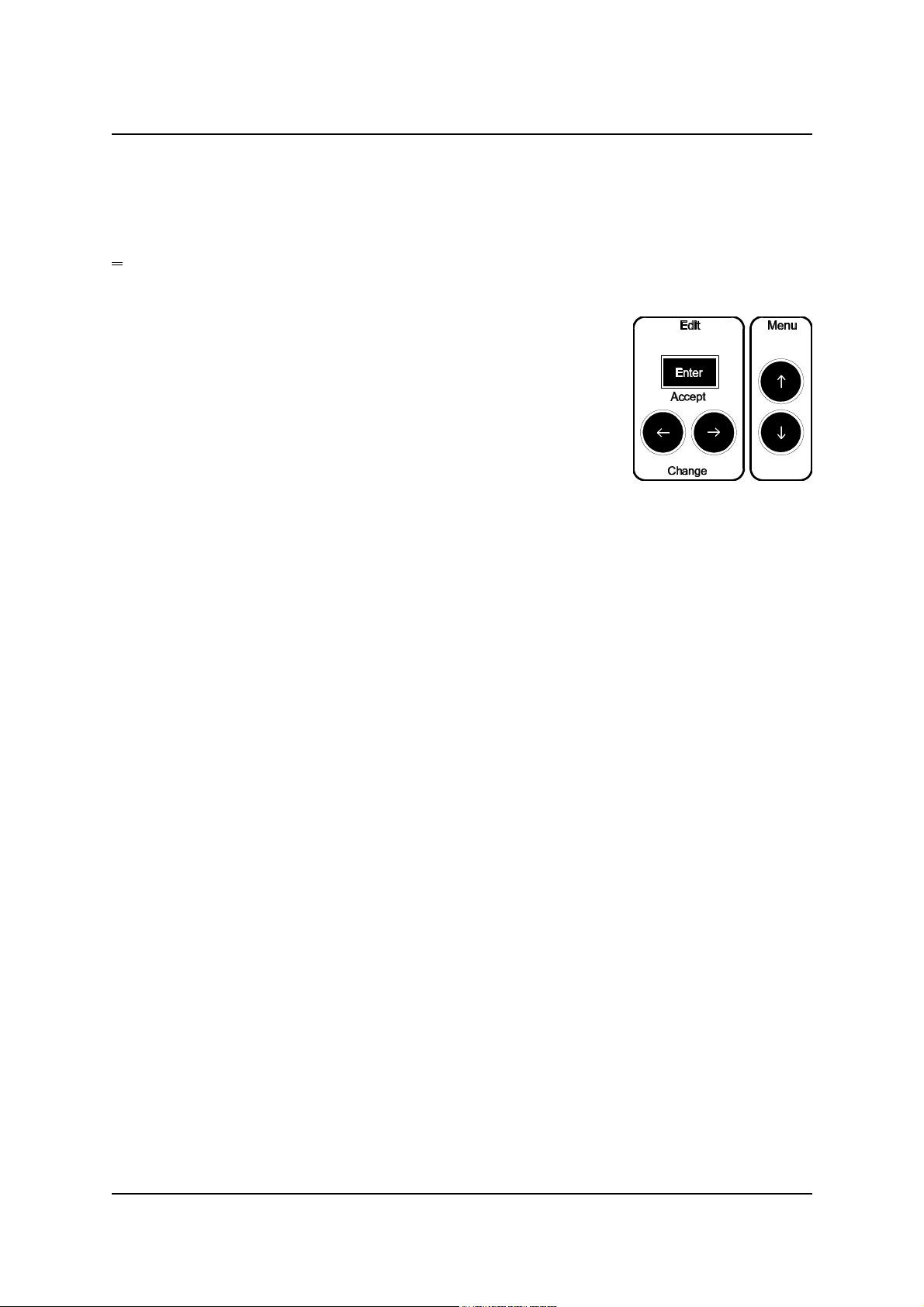
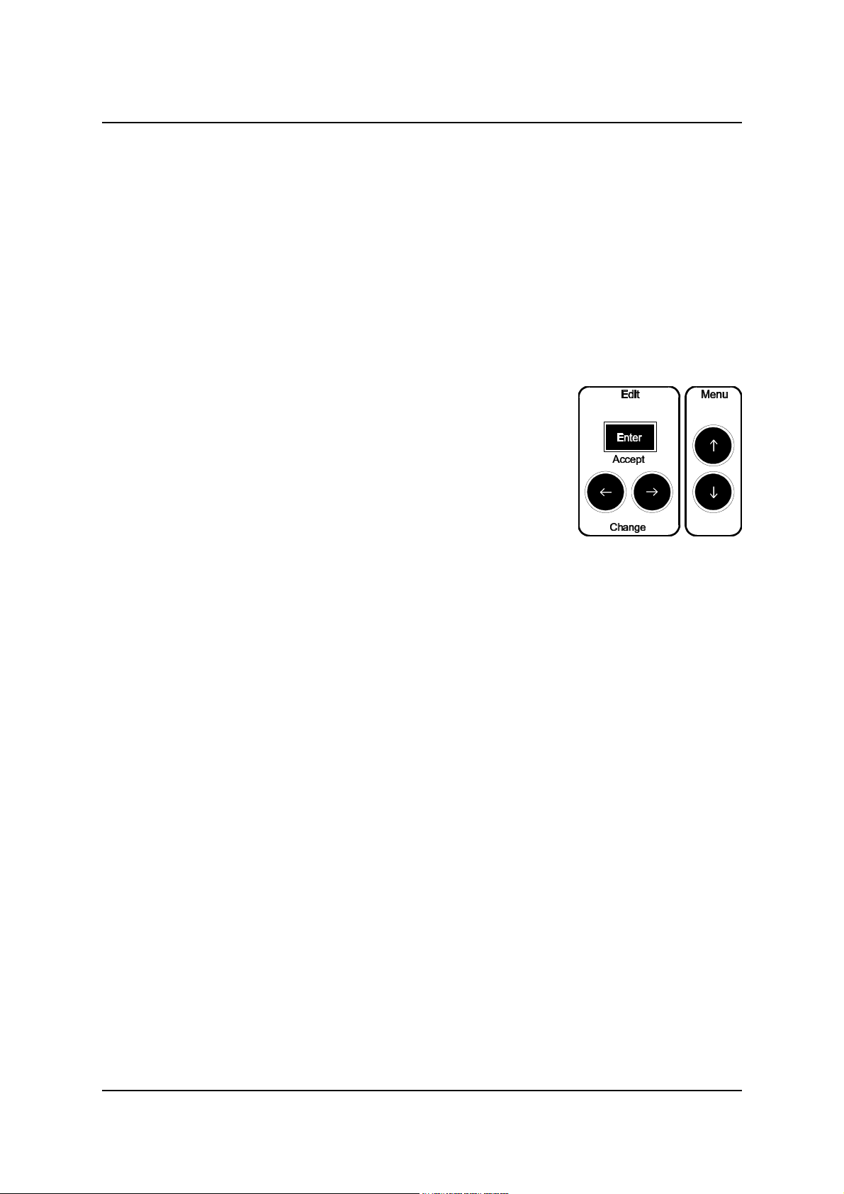
Push-buttons in the Edit and Menu boxes are referred to as ‘keys’. Push-buttons in the
Configuration/Stores box are referred to as ‘buttons’.
When a Menu Controls key is referred to by name, the name is enclosed in square
brackets thus : [Enter].
When a Store Controls button is referred to by name, the name is enclosed in angle
brackets thus: <A-D Modes>.
When text is quoted from the 2x16 character LCD display the text will be printed in a
special font thus : Level: dBFS.
When an LED from the System State Indicators is referred to by name, the name will be
enclosed in double quotes thus : “24bit”.
Issue 0.2 © Prism Media Products Limited
11 August 1998 Page 4 of 58
Page 5

Prism Media Products Limited AD-2 Dual-rate A/D converter
Operation Manual
1.2. Terminology for high-sampling rate interfaces
A variety of terms are in use regarding high sampling-rate interfaces. For more
information about these interfaces see sections 6.2 and 6.3.
1.2.1. Split96 or 2-wire AES3 interfaces
For recording applications requiring 96 or 88.2kHz sampling a solution is to use two
channels of a 44.1/48 kHz device for each audio channel at the higher rate.
It is possible to use a machine such as a TASCAM DA-88 with a suitable AES3
interface adaptor (such as the Prism Sound MR-2024T) to record stereo 88.2 or 96
kHz audio. Using the MR-2024T, this can be done with up to 24-bit precision.
This method of interfacing between equipment is referred to variously as ‘Two-wire’ or
‘Split 96kHz’. Using this method, recordings can be made at sample-rates of 88.2 and
96.0kHz.
These recordings cannot be replayed or copied without a suitable D/A converter or
format converter and sample-rate converter (for 44.1k/48k CD and DAT).
In the AD-2 menu system, references to this mode of operation are made using the
term ‘Split96'; in the Factory Presets the term ‘2wr’ (two-wire) is also used.
1.2.2. Double speed AES3, or 1-wire interfaces
Some manufacturers have implemented high sample-rate interfaces by operating an
AES3 interface at twice the normal speed. Equipment with only this type of interface
cannot be directly connected to equipment only supporting 2-wire or Split96 operation.
This is often referred to as ‘Double-speed’ or ‘One-wire’ AES.
In addition to high-sample-rate A/D conversion, the AD-2 can provide all the necessary
format and sample-rate conversion for monitoring using 44.1k/48k equipment.
The AD-2 supports both 1-wire and 2-wire formats for 88.2 and 96.0kHz operation for
digital input and output.
The Prism Sound DA-2 provides D/A conversion at sampling rates from 32kHz to
96kHz and will deal with 2-wire or 1-wire high-sample-rate interfaces in addition to the
normal AES3/IEC958 and SDIF-2 interface formats.
Issue 0.2 © Prism Media Products Limited
11 August 1998 Page 5 of 58
Page 6

Prism Media Products Limited AD-2 Dual-rate A/D converter
Operation Manual
2. GETTING STARTED
2.1. Unpacking your AD-2 Dual-rate A/D converter
Check that you have the correct power lead with your AD-2 and that they and the
packaging are undamaged. Check that your unit is set for operation at the mains
voltage appropriate for your area. See section 7.7 for more details.
** WARNING ** If the unit has been transported or stored at a low temperature
and is unpacked in a warmer environment there is a danger of
condensation. This could cause the AD-2 to malfunction, so to
avoid problems, allow the unit to warm up to room temperature
for at least 1 hour before use.
Please keep the packaging for re-use.
2.2. Using the AD-2 for the first time
Be ready to check the firmware revision number when the unit is powered on for the first
time. Following switch on, this is briefly displayed as follows:
Prism Sound
Dream AD-2 V1.0x ; The ‘x’ means that this digit may be any number.
If a different version is indicated, contact Prism Sound or your local supplier.
The AD-2 will perform brief initialization, in which all the LEDs are turned on
momentarily (this allows a quick visual check of the LEDs). The unit will settle with the
following text at the start of the first line of the LCD display:
Level : dBFS
On leaving the factory, the settings of the AD-2 will be those of A-D mode Factory
Preset #1, which are as follows:
" A-D mode
" Main output at 96kHz sampling in 2-wire (Split96) format using both XLR
outputs; Main also on the BNC connectors in Split96.
" Aux output on TOSlink optical and RCA Phono outputs, set to 96kHz sampling,
24-bit.
" External Wordclock reference enabled (defaults to internal if none).
" Analogue input amplitude for full digital code (0dBFS) set at +18dBu. This is
consistent with line-up at +4dBu/0VU with 14dB headroom.
If these settings are not suitable, either use the Set-up Wizard or check the table of
presets in sections 2.3 and 2.4 and select one using the method described on page 11.
Issue 0.2 © Prism Media Products Limited
11 August 1998 Page 6 of 58
Page 7

Prism Media Products Limited AD-2 Dual-rate A/D converter
Operation Manual
Issue 0.2 © Prism Media Products Limited
11 August 1998 Page 7 of 58
Page 8

Prism Media Products Limited AD-2 Dual-rate A/D converter
Operation Manual
2.3. A-D mode Factory Presets
A-D MODES
Store
Sync/
DI
Lineup
Main
O/P
Store number 1 2 3 4
Text desc’n
Sync source WCK or INT* WCK or INT* WCK or INT* WCK or INT*
Sync/DI port WCK BNC WCK BNC WCK BNC WCK BNC
DRE decode OFF** OFF** OFF** OFF**
I/P for 0dBFS +18dBu*** +18dBu*** +18dBu*** +18dBu***
Left ch. trim 0dB*** 0dB*** 0dB*** 0dB***
Right ch. trim 0dB*** 0dB*** 0dB*** 0dB***
Sample Rate 96.0 kHz 96.0 kHz 44.1 kHz 96.0 kHz
Wordlength / 24-bit Linear** 24-bit Linear** 24-bit Linear** 24-bit Linear**
DRE encode
Ports XLR1 USplit96 (2-wire) U at 2x speed U AES3 @44.1k USplit96 (2-wire)
XLR2 USplit96 (2-wire) U at 2x speed U AES3 @44.1k USplit96 (2-wire)
BNC1 USplit96 (2-wire) U at 2x speed
BNC2 USplit96 (2-wire) U at 2x speed
A-D:96k,24b A-D:96k,24b A- A-D:96/24,
2XLR 1XLR D:44k1,24b&16b 44/16
LEFT CH. (1-wire) LEFT CH.
RIGHT CH. (1-wire) RIGHT CH.
LEFT CH. (1-wire)
RIGHT CH. (1-wire)
Opt. In the Factory Presets, these output
ports are used for the Aux Output
(Curve 2) (Curve 2)
ports are used for the Main Output
LEFT CH. LEFT CH.
RIGHT CH. RIGHT CH.
Aux
O/P
RCA
Sample Rate (Follows Main) (Follows Main) (Follows Main) Set to 44.1 kHz
Wordlength / 24-bit Linear** 24-bit Linear 16-bit with SNS 16-bit with SNS
DRE encode Noise-Shaping Noise-Shaping
Ports XLR1 In the Factory Presets, these output
XLR2
BNC1 USDIF-2 USDIF-2
BNC2 USDIF-2 USDIF-2
Opt. U at 2x speed U at 2x speed U IEC958/SPDIF U IEC958/SPDIF
RCA U at 2x speed U at 2x speed U IEC958/SPDIF U IEC958/SPDIF
* WCK may be any standard rate (32, 44.1, 48, 88.2 or 96kHz). If none is present, the AD-2
defaults to Internal sync.
** DRE modes are not included in the Factory Presets. See sections 3.8 and 4.6.
Issue 0.2 © Prism Media Products Limited
11 August 1998 Page 8 of 58
Page 9

Prism Media Products Limited AD-2 Dual-rate A/D converter
Operation Manual
*** The default line-up setting is digital full code (0dBFS) at +18dBu with no fine trim. Setting of
line-up by stores is possible, but is initially disabled (preferences menu) see section 4.6.
Issue 0.2 © Prism Media Products Limited
11 August 1998 Page 9 of 58
Page 10

Prism Media Products Limited AD-2 Dual-rate A/D converter
Operation Manual
2.4. D-D mode Factory Presets
D-D MODES
Store
Sync/
DI
Main
O/P
Store number 1 2 3 4
Text desc’n
Sync source DI* DI* DI* DI*
Sync/DI port AES/XLR1 2-wire/XLR1&2 AES/XLR1 2-wire/XLR1&2
DRE decode OFF** OFF** OFF** OFF**
Sample Rate 44.1 kHz 44.1 kHz As Input 88.2 or 96.0 kHz
Wordlength / 24-bit Linear 24-bit Linear 16-bit with SNS 16-bit with SNS
DRE encode* Noise-Shaping Noise-Shaping
Ports XLR1 U AES3 U AES3 U AES3 UAES3(1-wire)
XLR2 U AES3 U AES3 U AES3 UAES3 (1-wire)
BNC1
BNC2 In the Factory Presets, these output
Opt.
RCA
SRC:AES644,24&1 SRC:2wr644,24&1 SNS2:AES616b,AE SNS2:2wr616b,AE
6 6 S S
32, (44.1), 48, 88.2, 96kHz 32-96kHz 88.2, 96kHz
88.2, 96kHz
(32-96kHz) (as input)
(Curve 2 or 2/96) (Curve 2 or 2/96)
ports are used for Aux. Output.
Aux
O/P
Sample Rate Follows Main Follows Main Follows Main Follows Main
(44.1 kHz) (44.1 kHz) (32-96kHz) (88.2/96kHz)
Wordlength / 16-bit with SNS 16-bit with SNS 16-bit with SNS 16-bit with SNS
DRE encode* Noise-Shaping Noise-Shaping Noise-Shaping Noise-Shaping
(Curve 2) (Curve 2) (Curve 2) (Curve 2)
Ports XLR1 In the Factory Presets, these output
XLR2
BNC1 USDIF-2 USDIF-2 USDIF-2 USDIF-2
LEFT CH. LEFT CH. LEFT CH. LEFT CH.
BNC2 USDIF-2 USDIF-2 USDIF-2 USDIF-2
RIGHT CH. RIGHT CH. RIGHT CH. RIGHT CH.
Opt. UIEC958/SPDIF UIEC958/SPDIF UIEC958/SPDIF U IEC958/SPDIF
RCA UIEC958/SPDIF UIEC958/SPDIF U IEC958/SPDIF U IEC958/SPDIF
ports are used for Main Output
* If no DI is present, the AD-2 defaults to Internal sync.
** DRE modes are not included in the Factory Presets.See sections 3.8 and 4.6.
2x speed/1wire
2x speed/1wire
Issue 0.2 © Prism Media Products Limited
11 August 1998 Page 10 of 58
Page 11

Prism Media Products Limited AD-2 Dual-rate A/D converter
Operation Manual
2.5. Selecting one of the Factory Preset configurations
If the configuration at power-up is not suitable for your application, you may find that
another Factory Preset will be satisfactory.
2.5.1. Preview and select a Factory Preset
To view the text descriptions of the Factory Preset configurations:
Step 1 Select <A-D Modes> or <D-D Modes>
Step 2 Select <Factory Presets>
Step 3 Select each preset <1> to <4>
Check the description in the display. The LED above each button
will flash while in preview mode.
Repeat step 3 until you have chosen the store that seems most suitable.
Pressing the store button a second time will return the AD-2
unchanged to the normal operating state; alternatively this
control will time out and the unit will revert to normal
automatically after about 30 seconds without changing any
settings.
Step 4 To recall the store press [Enter].
If, having tried all of the stores, none is suitable you may either use the menu system
(see section 4.6) to create a fully-customized configuration, or for simple A-D modes
you may use the ‘Setup Wizard’ (see section 4.3).
2.6. Check the analogue line-up (headroom)
Connect a source of analogue audio to the inputs at the rear of the unit. Ensure that the
source is playing audio and check the meters on the front of the AD-2. A useful check
is to send a 0VU line-up tone. If all is well, this should illuminate the AD-2 meters up to
the -14dB division (in practice the LED at -14 may be on OR off for nearly exact 0VU
line-up with +18dBu headroom).
Issue 0.2 © Prism Media Products Limited
11 August 1998 Page 11 of 58
Page 12

Prism Media Products Limited AD-2 Dual-rate A/D converter
Operation Manual
2.6.1. Adjust the maximum analogue input level (line-up)
Step 1 repeatedly press the [99] button in the Menu panel until
A-D Mode Setup is displayed in the top line of the display
Step 2 press “Enter”
Step 3 Use the[66] and [77] buttons to set the desired maximum input level.
It is not necessary to manually return to the normal operating display as
the AD-2 will time out automatically, but this can be done manually by
repeatedly pressing [88]. For more information about this adjustment, refer
to section 4.6.
NOTES :
Take care to check that the source is at the correct level before adjusting the AD-2
maximum input level.
The maximum analogue input level setting is included in stored configurations and can
therefore be changed by selecting another store. However, this can be disabled in the
‘Preferences’ menu and the disabled state is the default on leaving the factory.
Connect one of the AD-2 outputs to a suitable digital recorder or D/A converter.
The Prism Sound DA-2 D/A converter is highly recommended as a companion for the
AD-2. Select monitoring of the AD-2 output on the recorder or D/A converter.
Ensure that if 24-bit output is used from the AD-2 that the recorder and/or D/A converter is
capable of handling 24 bits.
Monitor the recorder or D/A output and check that the source is properly reproduced.
You may now proceed with recording.
2.7. Synchronization
The synchronization settings for the A-D Factory Presets are all similar. An external
wordclock is specified on the BNC WCK input connector. A wordclock signal may be
provided at any of the standard rates and the AD-2 will lock to it even though its outputs
may be running at a different, fixed sample rate. For more information about
synchronization of the AD-2, see section 5.
If a sync source is not connected, the AD-2 will by default operate from its internal
precision clock reference.
Issue 0.2 © Prism Media Products Limited
11 August 1998 Page 12 of 58
Page 13

Prism Media Products Limited AD-2 Dual-rate A/D converter
Operation Manual
2.8. Introduction to the Setup Wizard
The Setup Wizard helps you create custom A-D configurations. It provides choices of
sample rate, wordlength, synchronization, maximum input level and digital interface
format.
The Setup Wizard will allocate Main Output to all output connectors.
To use the Setup Wizard, press the <Setup Wizard> button on the far right of the AD-2
front panel and follow the prompts in the LCD display. The first prompt will be:
* Setup Wizard *
Enter to start.
Press [Enter], and the following will be displayed:
To configure a
basic A-D mode..
Press [Enter] to continue, then you will see:
Use Internal
Ref Sync?
At this point, you may confirm the internal sync selection or change it using the [77] and
[66] (Edit/Change) keys. Repeated use of either key will cycle through the list of
alternative selections.
When the desired selection is displayed, confirm it using the [Enter]/Accept key.
Continue with the process of selecting settings until you see:
Setup Wizard is
now finished...
Press [Enter] and you will see:
You can save
this setup...
Press [Enter] and you will see:
Empty stores ->
are flashing...
Issue 0.2 © Prism Media Products Limited
11 August 1998 Page 13 of 58
Page 14

Prism Media Products Limited AD-2 Dual-rate A/D converter
Operation Manual
At this point, if you have not already saved any configurations to user stores, all of the
store LEDs above buttons <1> to <4> will be flashing.
If you do not wish to store your setup, simply press [Enter], ignore the prompt to select
a store and press [Enter] again. You will see:
Setup not
Saved
Then press [Enter] to finish.
If you wish to store your custom setup, press one of the 4 store buttons; you can
overwrite an existing store if you wish - in this case you could select one that was not
flashing.
You will then see:
Setup saved as
xxxxxxxxx by Wzd
Press [Enter] to finish and return to the normal level display.
You may then wish to modify the setup such as to set an alternative function and output
connector for the Auxiliary output.
Do this by using the [99] and [Enter] keys to select the relevant menu or sub-menu;
edit/change the parameter with the [77] and [66] keys and confirm the new selection with
[Enter].
For more details see section 4.6.
Issue 0.2 © Prism Media Products Limited
11 August 1998 Page 14 of 58
Page 15

Prism Media Products Limited AD-2 Dual-rate A/D converter
Operation Manual
3. FREQUENTLY-ASKED QUESTIONS (FAQs)
This section provides several ‘how to ....’ answers in response to a range of frequently-
asked questions.
3.1. What do the flashing !!! Characters mean in the display?
These indicate a warning condition and further explanation can be seen by pressing
[66].
A common display is
Warnings: [Lvl]
*Bad External DI
This means that a Digital Input (DI) signal is expected but not present or is incorrect..
In the default state of the AD-2, if an external Wordclock is not connected, this warning
is shown accompanied by a solid ON “Local” LED and a flashing “WCK” LED.
If this display appears at other times, use the [66] key to investigate. See Section 4.6.
3.2. Can I assign the Aux output to one of the XLR connectors?
Yes, but take care not to confuse the functions of XLR 1 & 2 if you assign them
separately with Main and Aux generating different audio formats.
3.3. How can I enable headroom setting by the stores?
The AD-2 allows you to set the input level at which digital full-scale (0dBFS) is reached
using the 0dBFS: setting in the A-D Mode Setup sub-menu. The headroom limit
can be considered as being the same as the maximum input level. Clipping will occur
cleanly at this point. Then use the [99] key to get to the Preferences Menu. Press
[Enter]. Press [99] repeatedly until Load A-D Gains:N is displayed. Then use the
[66] key to change the setting to Yes and finally Press [Enter].
Once you have done this, any future store save and load operations will respectively set
and restore the store’s maximum input level (line-up) setting.
USE THIS WITH GREAT CARE!
Issue 0.2 © Prism Media Products Limited
11 August 1998 Page 15 of 58
Page 16

Prism Media Products Limited AD-2 Dual-rate A/D converter
Operation Manual
3.4. Can I drive 2 wire and 1-wire 96kHz at the same time?
Yes. You could use any of the A-D Factory Presets 1, 2 or 4 as a base or you could
start with the Set-up Wizard and set 96k 1-wire 24-bit output.
Then, you must modify the resulting setup to obtain the formats you need.
Starting from A-D Factory Preset 2;
Factory Preset Store 2 places the Main Output on the XLR and BNC connectors in 1-
wire (2x speed) AES-3id format. XLR1 & 2 can then be configured as 2-wire, leaving 1wire (i.e. 2x speed AES3) 96k on the BNC outputs.
First ensure that Factory Preset Store 2 is loaded. Press <A-D Modes>, then
<Factory Presets>, then <2>. You should see A-D:96k,24b 1XLR. Press [Enter]
to load the store.
Then, use the [99] key to select the Dig O/P Assign menu; press [Enter] and then
press [99] until the XLR2 O/P:Main display is obtained.
Use [77] to select Split96 and then press [Enter]. Check that the yellow “Link” LED
is now on adjacent to the XLR1 & 2 LEDs in the “Output Assignment” box.
Now, the XLRs are driving 2-wire and the BNCs are driving 1-wire, 2x speed AES3.
3.5. How do I do sample-rate conversion?
A common requirement is down-conversion from a high sample-rate to a low rate such
as 44.1kHz for CD release.
Press <D-D Modes>, <Factory Presets> and then <1> for 1-wire or <2> for 2-wire
and then [Enter] to load the store.
See section 2.4 for details of Factory Preset stores D-D 1 and 2. To change the output
sample rate from the preset 44.1kHz, press [99] until
Main O/P Setup is displayed, then [Enter].
Use the [77] and [66] keys to select the desired output sample-rate and then press
[Enter] to confirm the selection.
Issue 0.2 © Prism Media Products Limited
11 August 1998 Page 16 of 58
Page 17

Prism Media Products Limited AD-2 Dual-rate A/D converter
Operation Manual
3.6. Can the AD-2 convert up to 96kHz from 44.1kHz?
Yes. Use D-D Factory Preset Store 1 as a base. (Store 2 will be less useful as it
specifies 2-wire input and this would need to be changed.)
Press <D-D Modes>, <Factory Presets> and then <1>. Press [Enter] to load the
store.
See section 2.4 for details of D-D Factory Preset stores.
Now change the output sample rate from the preset 44.1kHz to 96 or 88.2kHz.
Press [99] until Main O/P Setup is displayed, then [Enter]. Use the [77] and [66] keys
to select the desired high sampling rate, followed by [Enter] to confirm the selection.
The AD-2 is now ready to up-convert using AES3 input on input XLR1 and generating
1-wire (2x speed) output on XLR1 and XLR2.
3.7. How do I change the synchronization to AES3?
This can be set starting from any of the A-D mode Factory Presets by using the Menu
controls. Start using the [99] control to locate the D-D Mode Setup sub-menu. Press
[Enter] and then use the [77] and [66] keys to select XLR1 or XLR2. Confirm the
selection with [Enter].
You may like to save this in a user store. See section 4.5.2 for details.
The AD-2 can accept sync at a frequency which differs from its outputs. For more
information about the highly flexible synchronization modes of the AD-2, see section
5.
3.8. What is DRE?
Dynamic Range Enhancement (DRE) is a process designed for the increasing the
dynamic range of 16-bit recording channels, such as DAT, CD-R, or 1630+U-matic,
when further post-processing is required. It requires an encode process on recording
and a decode process on playback. It is suitable for applications where 20-bit dynamic
performance is desired of the recorder but only a 16-bit recorder is available, and
where the requirement for a decode process is not a problem. The AD-2 Dual-rate A/D
converter can encode DRE signals from analogue or digital sources, and can also
decode them (in digital to digital mode) to transfer the high resolution signal, encoded
on a 16-bit tape, onto a 20 bit digital audio workstation. (The Prism Sound Dream DA2 can be used to provide analogue monitoring of the encoded signal.)
Issue 0.2 © Prism Media Products Limited
11 August 1998 Page 17 of 58
Page 18

Prism Media Products Limited AD-2 Dual-rate A/D converter
Operation Manual
4. OPERATION REFERENCE
To reduce front-panel and operational complexity, the control of the AD-2 is provided by
means of various preset configurations complemented by a menu system which allows
access to all operating parameters individually.
You may choose a variety of methods to obtain your desired configuration:
" Menu system
" Factory Preset stores
" User stores (if loaded)
" Setup Wizard
All the control settings are saved in permanent memory so that they are remembered
when the unit is off.
4.1. General configuration rules
The AD-2 is a powerful and flexible tool and these benefits bring with them a degree of
complexity.
In addition to the operating methods mentioned above, there are several guidelines that
are worth remembering when trying to set up complex configurations.
1. Sampling rate for Main and Aux can generally be set independently. However,
only Aux can be set to 32kHz sampling.
2. If Aux is high-rate (88.2 or 96.0kHz) then the sample-rates for Main and Aux must
be the same.
3. In A-D mode, if Main is low rate (44.1 or 48.0kHz) the sample-rates for Main and
Aux must be the same.
4. If the AD-2 is sample-rate converting in D-D mode so that there are different
input and output sample-rates, then Main and Aux must run at either the input
sample rate or the sample-rate-converted rate.
5. Aux may not drive Split96 (2-wire) format.
Issue 0.2 © Prism Media Products Limited
11 August 1998 Page 18 of 58
Page 19

Prism Media Products Limited AD-2 Dual-rate A/D converter
Operation Manual
4.2. To reset the AD-2 to its factory default state
USE THIS WITH CARE, AS THE USER STORES WILL BE CLEARED.
Use the [99] key to enter the menu system and hold it down until Preferences is
displayed. Press [Enter], then press [99] until you see:
Reload Factory
Defaults/Stores?
Press [Enter] and at the prompt Enter to Accept press [Enter] again.
4.3. Setup Wizard
The Setup Wizard helps you create custom A-D configurations. It provides choices of
sample rate, wordlength, synchronization, maximum input level and digital interface
format.
The Setup Wizard will allocate Main Output to all output connectors.
If you require an Auxiliary output with different settings, you can use the result of the
Setup Wizard as a base and then change the Auxiliary output and Output connector
assignments using the Menu system.
To use the Setup Wizard, press the <Setup Wizard> button on the far right of the AD-2
front panel and follow the prompts in the LCD display. The first prompt will be:
* Setup Wizard *
Enter to start.
From this point forward, continue or confirm a selection using the [Enter]/Accept key or
change the selection using the [77] and [66] (Edit/Change) keys. Repeated use of either
key will cycle through the list of alternative selections.
When the desired selection is displayed, confirm it using the [Enter]/Accept key.
Continue with the process of selecting settings until you see:
You can save
this setup...
Issue 0.2 © Prism Media Products Limited
11 August 1998 Page 19 of 58
Page 20

Prism Media Products Limited AD-2 Dual-rate A/D converter
Operation Manual
Press [Enter] and you will see:
Empty stores ->
are flashing...
At this point for each empty user store, the corresponding LED
above the store button will be flashing.
If you do not wish to store your setup, simply press [Enter], ignore the prompt to
select a store and press [Enter] again. You will see:
Setup not
Saved
Then press [Enter] to finish. Alternatively..
If you wish to store your custom setup, press one of the 4 store buttons; you can
overwrite an existing store if you wish - in this case you could select one that was not
flashing. You will then see:
Setup saved as
xxxxxxxxx by Wzd
Note : The Setup Wizard creates a text description which is displayed in the bottom line of the display (xxxxxx’s
indicate where the description is displayed). This is the text description for the store. It can be changed by
editing the store description according to section 4.5.4.
Note: The LED’s continue flashing after store selection - your selection, whether an empty or used store, is
confirmed after the next step....
Press [Enter] to finish and return to the normal level display.
You may then wish to modify the setup such as to set an alternative function and output
connector for the Auxiliary output. See section 4.6.
4.4. Program level meter
The Program level meter is a peak reading meter with one sample attack time and
normal or peak hold display modes.
The exact level is displayed on the LCD display (in its normal mode of operation) for
both left and right channels.
The default mode is ‘normal’ in which transient meter deflections will be followed by a
controlled decay of the indication and where the occurrence of overloads is momentary
[“Over” indicator ON]. [Overs are stretched for a minimum period so that brief overs
Issue 0.2 © Prism Media Products Limited
11 August 1998 Page 20 of 58
Page 21

Prism Media Products Limited AD-2 Dual-rate A/D converter
Operation Manual
will still be clearly visible]. Also, the text display of peak level is updated sufficiently
slowly that the values can be read while the signal amplitude is changing.
Using the [Enter] key the hold mode can be toggled between normal and indefinite
hold. For indefinite hold mode, the peak level displayed in the LCD will not decay but
will be replaced each time higher peak levels are detected.
The highest level measured since indefinite hold was selected will be indicated by a
single LED in the bargraph meter being lit while the dynamic signal level is still
indicated by a moving bar. For test tones, the single LED showing the peak level may
not be evident until the test tone is removed or reduced in level.
4.4.1. Overload threshold
The overload threshold is -0.05dBFS.
The overload need only be present for one sample in order to trigger the overload
detector. This serves as a warning only, and the ultimate test is to listen. Any filtering of
overload indications is regarded by Prism Sound as potentially dangerous.
4.4.2. “Error” indicator
The “Error” indicator may be lit for the following reasons only:
" Digital Input (DI) out of lock : LED on continuously
" Digital Input (DI) experiencing Bi-phase or Parity errors or or sample-slipping :
LED flashing.
4.5. Store Controls
The AD-2 has a large number of control parameters and to simplify and speed up its
operation a system of preset stores is provided, complemented by a menu system for
adjustment of any parameter individually.
The best way of using the AD-2 is to become familiar with the contents of the Factory
Preset stores and to select the one which is the best fit with your requirement. Then you
can customize it by changing just a few parameters.
The configuration can then be saved in one of the user stores for re-use.
The AD-2 stores are organised in two banks of two stores : There are ‘Factory Preset’
and ‘User’ banks in each of the ‘A-D Modes’ and ‘D-D Modes’ banks. The following
table shows the store system organisation:
Issue 0.2 © Prism Media Products Limited
11 August 1998 Page 21 of 58
Page 22
Prism Media Products Limited AD-2 Dual-rate A/D converter
Operation Manual
Store system organization
MODE Store No. 1 2 3 4
A-D Factory Preset Factory Preset Factory Preset Factory Preset
A-D User User User User
D-D Factory Preset Factory Preset Factory Preset Factory Preset
D-D User User User User
For details of the Factory Preset stores, see sections 2.3 and 2.4.
4.5.1. Preview the description and load settings from a store
Before loading a new store it is advisable to preview the store description. This is
accomplished by the following procedure:
Step 1 From the normal Level: display, press either the
<A-D Modes> button or the <D-D Modes> button to
select the desired mode.
Step 2 If you wish to preview a Factory Preset store, press
<Factory Presets> and/or check that the
corresponding LED is lit.
Step 3 Press the selector button for the desired store i.e. one of <1> to <4>. The
corresponding LED will flash.
Step 4 Inspect the text description.
Step 5 Repeat steps 3 & 4 to preview other stores if desired.
You may then cancel the preview by pressing the same store button again [or by
pressing either the [88] or [99] keys, or by double pressing any other store button <1> to
<4> or <Setup Wizard>].
Step 6 To load the store, when in preview mode, press
the [Enter] key. This will set the AD-2 to the
settings contained in the selected store.
Issue 0.2 © Prism Media Products Limited
11 August 1998 Page 22 of 58
Page 23
Prism Media Products Limited AD-2 Dual-rate A/D converter
Operation Manual
4.5.2. Save settings to a user store
Prior to saving the AD-2 settings to one of the user stores you will probably have
created a custom configuration by one of the following methods:
" Using the (A-D modes) Setup Wizard (without saving at that time)
" Using an existing store (Factory Preset or User) and modifying it
" Creating it from scratch using the Menu controls
Before saving your settings to a user store it is advisable to preview the store to check
that it is empty or to make sure that you will not overwrite something that you wish to
keep.
Step 1 From the normal Level: display, press either the
<A-D Modes> button or the <D-D Modes> button
to select the appropriate mode.
Step 2 If you wish to preview a Factory Preset store, press
<Factory Presets> and/or check that the
corresponding LED is lit.
Step 3 Press the selector button for the desired store i.e. one of <1> to <4>. The
corresponding LED will flash.
Step 4 Inspect the text description. If the store is empty, the display will read
Empty Store.
Step 5 Repeat steps 3 & 4 to preview other stores if desired.
You may then cancel the preview by pressing the same store button again [or by
pressing either the [88] or [99] keys].
4.5.2.1. Saving to an empty store using the default store description
Step 6 Press the [Enter] key. A default store
description will be displayed in the top line of the
display. [The description can be edited at this
point or later - see below.]
Step 7 Press the [Enter] key again to accept the
default description. Finally, you will be
prompted to confirm the save operation with:
Enter to save
Issue 0.2 © Prism Media Products Limited
11 August 1998 Page 23 of 58
Page 24
Prism Media Products Limited AD-2 Dual-rate A/D converter
Operation Manual
Step 8 Press [Enter] again to confirm. Your current settings will be stored.
Alternatively, press [88] or [99] or the button under the flashing store LED to
cancel the store operation [or double press any other store button <1> to
<4> or <Setup Wizard>.]
4.5.2.2. Saving over an existing store using the default store description
Step 6 Change the store operation from ‘Load’ to
‘Save’ by pressing the [66] key.
Step 7 Press [Enter]. A default store description will
be displayed in the top line of the display. [The
description can be edited at this point or later -
see below.]
Step 8 Press the [Enter] key again to accept the
default description. Finally, you will be prompted to confirm the save
operation with:
Enter to save
Step 9 Press [Enter] again to confirm. Your current settings will be stored.
Alternatively, press [88] or [99] or the button under the flashing store LED to
cancel the store operation [or double press any other store button <1> to
<4> or <Setup Wizard>.]
4.5.2.3. Saving a store with your own store description
If you are saving to an empty store, use the procedure of section 4.5.2 up to and
including Step 6 in section 4.5.2.1.
If you are saving to a store that has already been used, follow the procedure of section
4.5.2 up to and including Step 7 in section 4.5.2.2.
Issue 0.2 © Prism Media Products Limited
11 August 1998 Page 24 of 58
Page 25
Prism Media Products Limited AD-2 Dual-rate A/D converter
Operation Manual
A default store description will be displayed in the top line of the display with a prompt
to continue, such as:
A-D User #1 ;note: the first character will be flashing
[fns] Enter=End
Step A Optional : You may clear the description or
select the default by pressing the [77] key. The
[77] and [66] keys are used to move the character
edit cursor along the display. There are two
additional positions which can be visualized as
being between the two ends of the display.
These correspond to two functions which are :
Deflt and Clear
The function (if selected) will be displayed on the bottom line of the
display. To activate the function press [99] or [88]. To abort the edit at any
time while changing the description double press any store button <1> to
<4> or <Setup Wizard>.
Step B You will be presented either with a text description with the first character
flashing, or with a blank string with a flashing cursor in the first character
position.
Move the cursor to the desired position using the [77] and [66] keys.
Step C Edit the character using the [88] and [99] keys. The character is selected
from a list of ASCII characters shown in the table below. Hold down the
edit keys to auto-repeat and search quickly for the desired character.
Step D Repeat Steps B & C until the desired description has been set.
Step E Press [Enter] to finish editing the description.
Step F Press [Enter] again to Save the store. Alternatively, press [88] or [99] or
the button under flashing store LED to cancel the store operation [or
double press any other store button <1> to <4> or <Setup Wizard>.]
Issue 0.2 © Prism Media Products Limited
11 August 1998 Page 25 of 58
Page 26

Prism Media Products Limited AD-2 Dual-rate A/D converter
Operation Manual
4.5.3. Character set for store descriptions
6 ! “ # $ % & ‘ ( ) * + , - . / 0 1 2 3 4 5 6 7 8 9 : ; < = > ?
@ A B C D E F G H I J K L M N O P Q R S T U V W X Y Z [ - ] ^
_ ` a b c d e f g h I j k l m n o p q r s t u v w x y z { | }
4.5.4. Editing the text description of a user store
This is performed by first loading the store as described in section 4.5.1 and then
saving it with your new text description as described in sections 4.5.2.2 and 4.5.2.3.
4.6. Menu system operation
The Menu system of the AD-2 provides access to all operating parameters so that
custom configurations of both A-D and D-D modes can be created and preferences
such as LED brightness and LCD contrast (and others) can be set.
It is advisable to store a custom configuration once it has been created.
Section 4.5 explains the procedure for storing your settings.
All the control settings are saved in permanent memory so that they are remembered
when the unit is off.
4.6.1. Normal Display - Peak Level indications
The normal display of the AD-2 once powered and initialized is:
Level: dBFS
< llll <> rrrr >
Where llll and rrrr are the peak amplitudes for the left and right channels,
expressed in dBFS (decibels relative to digital clip level). These are normally
displayed using a zero-attack peak hold algorithm with automatic decay to zero.
Indefinite peak hold is available and may be selected by pressing [Enter] at the normal
display level. The level units indication will change from dBFS to HOLD and back for
subsequent operations.
The ‘HOLD’ settings also applies to the Program Meter display. See section 4.4 for
more detail.
Issue 0.2 © Prism Media Products Limited
11 August 1998 Page 26 of 58
Page 27
Prism Media Products Limited AD-2 Dual-rate A/D converter
Operation Manual
A string of exclamation marks !!! may be seen from time to time at the top right of the
LCD display. This indicates a warning condition and the detail of the warning(s) can be
inspected using the [66] key.
If more than one warning condition is present, the various conditions will be displayed in
rotation on the bottom line of the display.
Press the [66] key again to return to the normal Level: display.
4.6.2. Navigating the menus
You may enter the menu system from the normal state using the
[99] key. You may leave it by using the [88] key; if leaving from
some point deeper in the menu system press the key repeatedly
until the normal display is obtained. You can also leave by
double-pressing any store button <1> to <4> or doublepressing the <Setup Wizard>.
Alternatively, leave the controls until the AD-2 times out. The
display will revert to normal automatically after a preset
time which can be set in the preferences menu (see below).
When navigating the menu system two types of display will be encountered. These are:
4.6.2.1. Sub-Menus
The sub-menus announce their purpose and prompt you to press [Enter] or [77]
or [66] to go into the sub-menu. Alternatively, [99] will skip past to the next main
menu item. Once in a sub-menu, [88] can be used to reverse out or [99] can be
used repeatedly to the end of the sub-menu and automatically on to the next
main-menu item.
Example:
Main O/P Setup ; this is a sub-menu, and
[Enter] ; shows that [Enter] will select the sub-menu
Issue 0.2 © Prism Media Products Limited
11 August 1998 Page 27 of 58
Page 28

Prism Media Products Limited AD-2 Dual-rate A/D converter
Operation Manual
4.6.2.2. Parameter selections
These display the parameter description and current setting.
Example:
Mode: A-D ; this allows setting of A-D or D-D mode, and
A-D D-D ; shows that A-D is selected.
The A-D on the top line is the current setting. On the bottom line is the set of
choices. The current position of the selection cursor is indicated by the selection
flashing (in the example above this is indicated by a double underline: A-D). If
there are more than can be accommodated on the display then the [77] and [66]
keys can be used to move the selection cursor and to scroll the list. This is
indicated by 6 and 7 at the ends of the display.
4.6.3. Changing the settings
When you have found the parameter that you want to change, use the [77] and [66] keys
to select the setting that you want.
Most AD-2 settings require confirmation of the change by pressing [Enter]. You will see
that the new setting is then displayed on the first line of the display. You can then
reverse out of the menus with [88] or wait for the unit to time out [or double-press any
store button <1> to <4>, or double-press the <Setup Wizard>].
Settings that do not require confirmation are :
" All of sub-menu A-D Mode Setup
- Peak input level (headroom limit)
- Left and Right channel gain trims
" In sub-menu Preferences
- LED Brightness
- LCD Backlight brightness
- LCD Contrast
Issue 0.2 © Prism Media Products Limited
11 August 1998 Page 28 of 58
Page 29
Prism Media Products Limited AD-2 Dual-rate A/D converter
Operation Manual
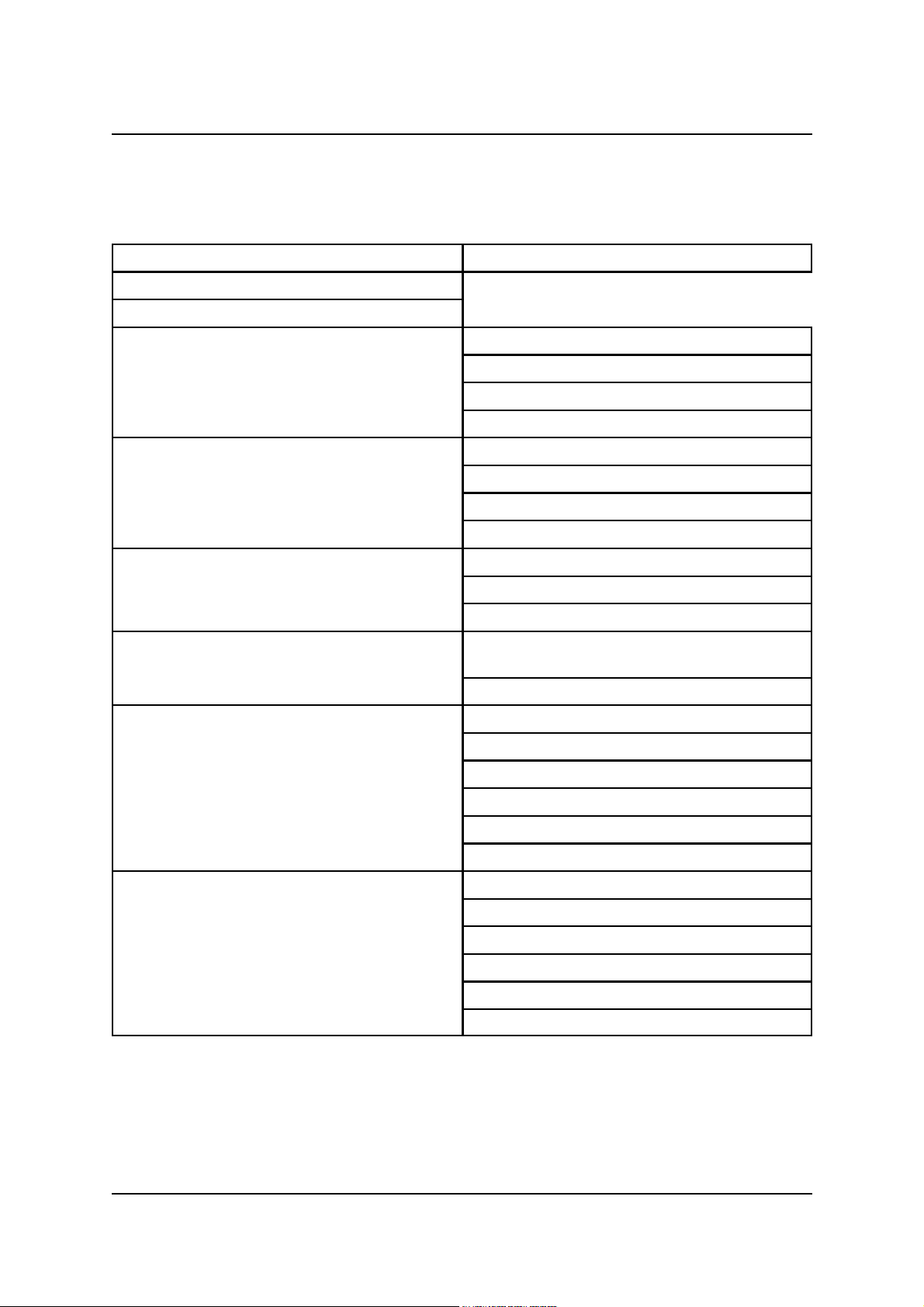
4.7. Menu system reference
Level Display Screen !!! [66] Warnings Screen [66]back to Level Display
Mode: A-D, D-D
Sync Source: Int, DI
Main Output Setup [Enter] fs: 44.1, 48, 88.2, 96, =DI
Wordlength: 16b, 20b, 24b
Quantizer: Flat, SNS1, SNS2, SNS3, SNS4
DRE Encode: Off, On
Aux Output Setup [Enter] fs: 32, 44.1, 48, 88.2, 96, =Main, =DI
Wordlength: 16b, 20b, 24b
Quantizer: Flat, SNS1, SNS2, SNS3, SNS4
DRE Encode: Off, On
A-D Mode Setup [Enter] 0dBFS: +5dBu to +28dBu in 0.5dBu steps
ChA Gain Trim: ±0.5dB in 0.05dB steps
ChB Gain Trim: ±0.5dB in 0.05dB steps
D-D Mode Setup [Enter] DI: XLR1, XLR2, XLR S96, BNC1, BNC2, BNC
S96, BNC SDIF-2, RCA, OPTO
DRE Decode: Off, On
Digital Output Assign [Enter] XLR1: Main, Aux
XLR2: Main, Aux, S96
BNC1: Main, Aux
BNC2: Main, Aux, S96, SDIF-2
OPTO: Main, Aux
RCA: Main, Aux
Preferences [Enter] Menu Timeout: 30s, 2m, 5m, Off
LED Brightness: 0..15
LCD Backlight Brightness: 0..15
LCD Contrast: 0..15
Load Analogue Gains from Stores: No, Yes
Reload Factory Defaults and Clear Stores...
Issue 0.2 © Prism Media Products Limited
11 August 1998 Page 29 of 58
Page 30
Prism Media Products Limited AD-2 Dual-rate A/D converter
Operation Manual
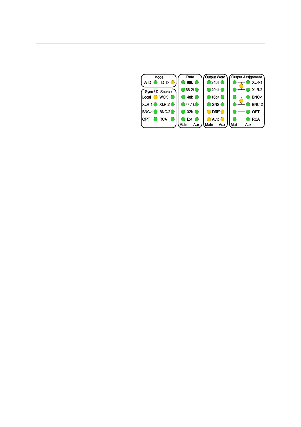
4.8. System State Indicator LEDs
In general the LED indications are
quite self-explanatory but there are
some which deserve further
explanation.
4.8.1. Flashing LED indicators
In general a flashing indicator provides a warning of some desired condition which is
not attained or is not attainable.
Common examples are :
" Synchronization set to external WCK and none connected.
- This is a functional configuration an needs no adjustment unless the
application demands that an external sync be used. If so, connect one to
the WCK BNC input. The LED will stop flashing when the WCK signal is
detected correctly.
" An illegal configuration is requested using the menu controls.
- This could be a condition such as attempting to set Split96 for the AUX
output on the BNC output connectors. This is not possible. In this case
the Yellow “Link” led between the “BNC-1” and “BNC-2" LEDS will be
flashing.
In both cases, further explanation of the warning condition can be found using the Menu
controls. The LCD display will show three exclamation marks !!!. Pressing the [66] key
will reveal a warning condition. If there is more than one, they will be slowly cycled
through on the display until [66] is pressed again.
It is possible to go directly from the warnings display mode to the menu controls using
[99] or to the setup wizard using <Setup Wizard> or to the store system using one of
the <1> to <4> store buttons.
Issue 0.2 © Prism Media Products Limited
11 August 1998 Page 30 of 58
Page 31
Prism Media Products Limited AD-2 Dual-rate A/D converter
Operation Manual
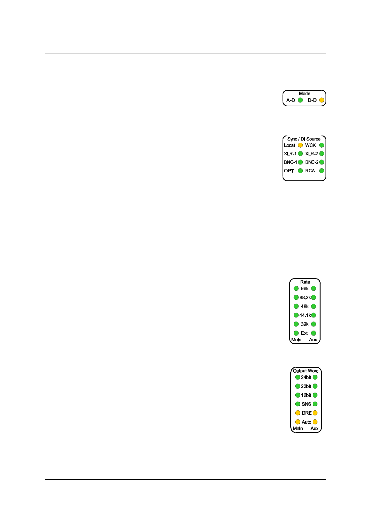
4.8.2. Mode indicators
There are two indicators in this group and they show the current mode of
the AD-2: A-D or D-D.
4.8.3. Sync/DI indicators
These indicate if the synchronization source is internal or external and if
external, the type of synchronizing signal.
If the AD-2 is in D-D mode, the input signal format is indicated.
For more information about synchronization modes, see section 5. For
information about digital inputs, see section 6.2.
When a ‘Split96' DI source or synchronizing source is selected both LEDs will be lit for
the respective format (XLR 1&2 and BNC-1&2).
If LEDs other than “Local” are flashing, the most likely cause is that an inappropriate or
non-functional reference is connected or no reference is connected.
4.8.4. Rate indicators
These indicate the sample-rate for the Main and Aux output channels.
Main cannot be set to 32kHz.
“Ext” indicates that the output channel (Main or Aux) is running at the
same rate as DI or an external Sync source (depending on mode of
operation).
4.8.5. Output Word Indicators
These indicate the wordlength settings for the Main and Aux output
channels.
“SNS” indicates that the Prism Sound Super-Noise-Shaping system is
active on the respective output. This provides a less noisy result when
used in conjunction with wordlength settings of less than 24 bits. For
more information see section 9.
“DRE” indicates that the Prism Sound Dynamic Range Enhancement
system is active on the respective output. This system is designed to be used with 16bit recorders and so when DRE is selected the output wordlength will be indicated as
“16bit”. For an explanation of this feature, see section 3.8.
Issue 0.2 © Prism Media Products Limited
11 August 1998 Page 31 of 58
Page 32
Prism Media Products Limited AD-2 Dual-rate A/D converter
Operation Manual
“Auto” indicates the state of the auto-dither system, which can intelligently set itself on or
off according to various conditions such as an input of digital zero or input of a
wordlength less than or equal to the output wordlength. For more information see
section 7.3.2.
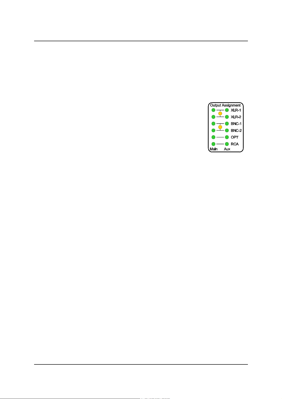
4.8.6. Output Assignment Indicators
These show the routing of the Main and Aux channels to the various
output connectors and give some indications about the format.
In between the XLR-1 and XLR-2 indicators and similarly between
the BNC-1 and BNC-2 indicators are yellow LEDs which indicate a
link between the two outputs.
This can have two alternative meanings:
4.8.6.1. Split96 or 2-wire mode
This LED is lit when either connector pair are configured in the Split96 or 2-wire mode
for either 88.2 or 96.0kHz sampling. For more information see section 6.3.
4.8.6.2. SDIF-2 format
This indicates that the SONY SDIF-2 format is selected. This may operate at low or
high sample rates but may only be selected on the BNC outputs. See section 6.3.
Issue 0.2 © Prism Media Products Limited
11 August 1998 Page 32 of 58
Page 33

Prism Media Products Limited AD-2 Dual-rate A/D converter
Operation Manual
5. SYNCHRONIZATION MODES
In A-D mode, the AD-2 Dual-rate A/D converter can be operated as either a clock
master or a clock slave. This is determined by the setting of the ‘Sync Mode’ menu.
If the Sync Mode is set to ‘Int’, then the Main and Aux output rates are set to the rates
requested in their respective menus, and are referenced to the AD-2s internal precision
reference.
If the Sync Mode is set to ‘DI’, then an external reference sync is used. The type of
external sync to be used, and on which connector, is defined in the ‘D-D Mode Setup’
menu: this may be an AES3, AES-3id, IEC958 or an SDIF-2 wordclock reference.
An unusual feature of the AD-2 is that this reference may be at any standard rate (i.e.
32kHz, 44.1kHz, 48kHz, 88.2kHz or 96kHz) and the Main and Aux outputs will be
locked to it precisely, whether or not they are set to sample at the same rate as the
reference. For example, a house sync at 48kHz may be used to synchronize an AD-2
producing simultaneous 44.1kHz and 96kHz outputs.
Alternatively, if the Main or Aux path is set to ‘=DI’ rather than having a particular
sampling rate specified, then that output path will sample at exactly the same rate as
the external reference. If an AES3 reference sync is selected and is designated as
‘Split96', then the sample rate of an output path following DI is set to twice the incoming
AES3 frame rate (i.e. 88.2kHz or 96kHz).
In D-D mode, the AD-2 Dual-rate A/D converter can similarly be operated as either a
clock master or a clock slave as determined by the setting of the ‘Sync Mode’ menu.
Normally, D-D Mode operation will be in external (’DI’) mode, where the AD-2 is locked
to the incoming digital audio signal (as specified in the ‘D-D Mode Setup’ menu). This
does not mean that the Main and Aux path outputs must necessarily be at the same rate
as the digital input - they may be specified to produce a different, sample-rateconverted output rate - but in any case their sampling frequency will bear a fixed
relationship to the incoming digital audio signal. Each of the Main or Aux outputs can be
precisely fixed to the incoming data rate by either selecting the same output rate for
that path as the current input rate, or by selecting the rate as ‘=DI’ to make the path
follow the rate of the incoming data, even if it changes.
If the Sync Mode is set to ‘Int’ in D-D Mode, then the AD-2 acts as a clock master: i.e. it
determines its output data rates from its high-precision internal clock, even though it
must accept its digital input data at the correct sampling rate (or, actually, at a standard
rate in fixed relationship to its output rate, since it may be rate-converting). It is
therefore essential that the sourcing equipment is locked to one of the outputs of the
AD-2 if correct interfacing is to be achieved.
Issue 0.2 © Prism Media Products Limited
11 August 1998 Page 33 of 58
Page 34

Prism Media Products Limited AD-2 Dual-rate A/D converter
Operation Manual
Operating the AD-2 as a clock master in D-D Mode may be desirable in a number of
situations, such as when processing the output of a digital audio workstation, or when
connected to an A-D converter with a poor-quality clock.
In either A-D or D-D mode, the question arises as to what output rates would be
assumed by Main or Aux output paths if they are set to ‘=DI’ but no external reference or
digital input is present (or if the Sync Mode is set to ‘Int’). In all such cases, the path’s
sampling rate defaults to 96kHz.
In all cases, care must be taken to ensure that the other digital audio equipment in the
system is either 'locked' to, or synchronous with, the AD-2.
Issue 0.2 © Prism Media Products Limited
11 August 1998 Page 34 of 58
Page 35

Prism Media Products Limited AD-2 Dual-rate A/D converter
Operation Manual
6. CONNECTORS
6.1. Analogue input connectors
Conventional connections from a balanced analogue source should use a screened
twisted pair lead. The AD-2 input pins 2 (+) and 3 (-) should be wired to the two
conductors of the pair and pin 1 to the cable screen. The other end of the cable should
be connected in a similar manner with the screen connecting to the chassis of the
source.
The AD-2 should be connected to an unbalanced analogue source using a screened
twisted pair lead, connected to the AD-2 as described above but at the analogue
source, pins 3 and 1 of the cable should both be connected to the output shield
connection. This provides shield continuity without the possibility of ground currents
flowing down the signal conductors.
6.2. Digital input connectors
The AD-2 Dual-rate A/D converter can accept digital audio inputs in a variety of
formats. These are:
AES3 professional AES/EBU on an XLR connector;
AES3 'Split96' professional AES/EBU on two XLR connectors, one per
channel at 88.2kHz or 96kHz sample rates;
AES-3id professional AES/EBU on a BNC connector;
AES-3id 'Split96' professional AES/EBU on two BNC connectors, one per
channel at 88.2kHz or 96kHz sample rates;
IEC958 consumer on an RCA/phono connector;
Optical consumer on a TOSLINK connector;
SDIF-2 professional on two BNC connectors plus wordclock;
DSD* one-bit data stream on two BNC connectors plus clock,
subject to an upgrade option
Two female XLR digital input connectors are fitted, which are used for either AES3 or
Split96 operation.
Three BNC digital input connectors are fitted, two of which are used for either AES-3id,
Split96, SDIF-2 or (with upgrade option) DSD operation. The third BNC is a wordclock
input for use with SDIF-2 inputs, or simply as a reference sync in A-D mode. The
wordclock connector doubles as a DSD clock input in that mode.
IEC958 (phono) and optical input connectors are dedicated, single function.
Issue 0.2 © Prism Media Products Limited
11 August 1998 Page 35 of 58
Page 36

Prism Media Products Limited AD-2 Dual-rate A/D converter
Operation Manual
The desired digital input format is selected in the 'D-D Mode Setup' menu. See
sections 4.6 and 4.7.
Note on Split96 operation: 'Split96' is a format for passing hi-sampled (88.2kHz or 96kHz) signals on AES3 or
AES-3id carriers at conventional bit-rates. This is achieved by using a single AES3 carrier per hi-rate channel
(it would normally carry a stereo channel). This format has the advantage that conventional, low-rate,
multichannel storage media can often be used to record 88.2kHz or 96kHz data. The format is described in
[Ref.8].
6.3. Digital output connectors
The AD-2 Dual-rate A/D converter can generate digital audio outputs in a variety of
formats. These are:
AES3 professional AES/EBU on an XLR connector;
AES3 'Split96' professional AES/EBU on two XLR connectors, one per
channel at 88.2kHz or 96kHz sample rates;
AES-3id professional AES/EBU on a BNC connector;
AES-3id 'Split96' professional AES/EBU on two BNC connectors, one per
channel at 88.2kHz or 96kHz sample rates;
IEC958 consumer on an RCA/phono connector;
Optical consumer on a TOSLINK connector;
SDIF-2 professional on two BNC connectors plus wordclock;
DSD* one-bit data stream on two BNC connectors plus clock,
subject to an upgrade option
Two female XLR digital output connectors are fitted, which are used for either AES3 or
Split96 operation.
Three BNC digital output connectors are fitted, two of which are used for either
AES-3id, Split96, SDIF-2 or (with upgrade option) DSD operation. The third BNC is a
wordclock output for use with the SDIF-2 output, or simply as a reference sync to other
equipment. The wordclock connector doubles as a DSD clock output in that mode.
IEC958 (phono) and optical output connectors are dedicated, single function.
The format and path assignment (Main or Aux) for each digital output connector is
selected in the 'Digital Output Assign' menu, as described in section 4.6 and 4.7.
Note on Split96 operation: 'Split96' is a format for passing hi-sampled (88.2kHz or 96kHz) signals on AES3 or
AES-3id carriers at conventional bit-rates. This is achieved by using a single AES3 carrier per hi-rate channel
(it would normally carry a stereo channel). This format has the advantage that conventional, low-rate,
multichannel storage media can often be used to record 88.2kHz or 96kHz data. The format is described in
[Ref.8].
6.4. Interconnect screens - the pin 1 conditions
Issue 0.2 © Prism Media Products Limited
11 August 1998 Page 36 of 58
Page 37

Prism Media Products Limited AD-2 Dual-rate A/D converter
Operation Manual
‘Screen' connects directly to the chassis for the digital XLR outputs and all BNC
connectors. Screen connects via a capacitor to the chassis for the digital XLR inputs.
The RCA digital coaxial connections are transformer isolated with the screen coupled
to the chassis using a capacitor at the connector.
The analogue input connector screens are connected to the chassis via a parallel
combination of resistor and capacitor. These components limit the shield currents that
could flow down the signal cables but provide continuity at radio frequencies.
Issue 0.2 © Prism Media Products Limited
11 August 1998 Page 37 of 58
Page 38
Prism Media Products Limited AD-2 Dual-rate A/D converter
Operation Manual
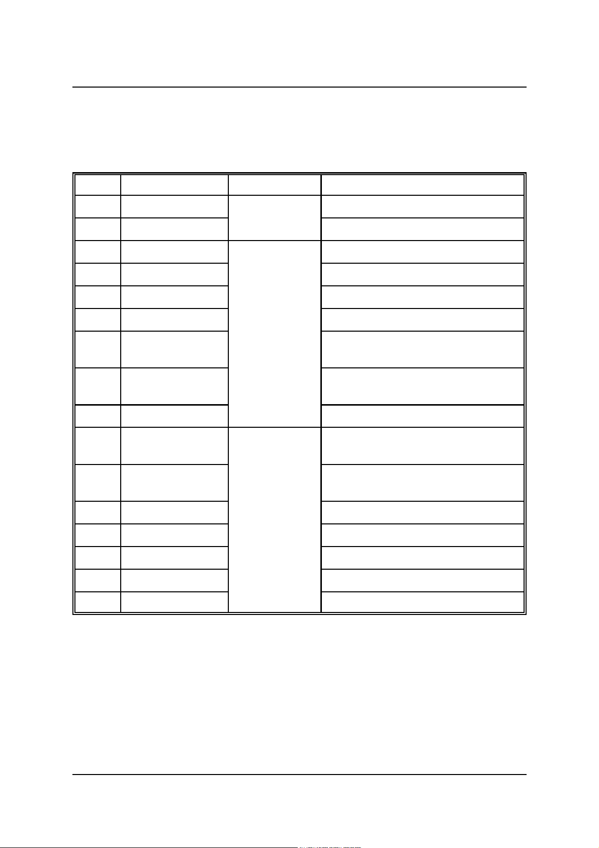
6.5. Connector table
Viewed from the rear, left to right, the connectors are as follows:
IEC320 - 3 pin Mains power inlet
A XLR-Female Analogue Channel A or Left
B XLR-Female Inputs Channel B or Right
DI1 XLR-Female AES3 and external REF (DARS)
DI2 XLR-Female AES3
DI3 OPTICAL Digital IEC958 optical
DI4 RCA-phono Inputs IEC958 coaxial
DI5 BNC-75S Multiple format
(L) AES-3id, SDIF-2 or DSD*
DI6 BNC-75S Multiple format
(R) AES-3id, SDIF-2 or DSD*
WCK BNC-75S Word-clock input (or DSD* clock)
DO5 BNC-75S Multiple format
(L) AES-3id, SDIF-2 or DSD*
DO6 BNC-75S Multiple format
(R) AES-3id, SDIF-2 or DSD*
WCK BNC-75S Digital Word-clock output (or DSD* clock)
DO4 RCA-phono Outputs IEC958 consumer format
DO3 OPTICAL IEC958 consumer format
DO1 XLR-Male AES3
DO2 XLR-Male AES3
XLR wiring conventions for both analogue and digital connections are:
Pin 1: Screen, Pin 2: Positive ('+', 'hot'), Pin 3: Negative ('-', 'cold');
*DSD inputs and outputs are a future upgrade option;
Issue 0.2 © Prism Media Products Limited
11 August 1998 Page 38 of 58
Page 39

Prism Media Products Limited AD-2 Dual-rate A/D converter
Operation Manual
7. TECHNICAL SPECIFICATION
Specifications quoted in this section are to AES17-1991 (ANSI S4.51-1991) [Ref. 3],
band-limited 20Hz-20kHz, at 96kHz sampling rate and output resolution of 24-bits,
except where stated. Analogue specifications are quoted with analogue input
sensitivity set to +18dBu (for digital full scale output) except where stated, and after a
30 minute warm-up period.
Specifications, offered in good faith, are subject to change without notice. Errors and
omissions excepted.
7.1. A-D mode Performance Specification
7.1.1. Distortion and noise
Dynamic range or signal-to-noise ratio (input sensitivity:+28dBu=0dBFS, 1kHz@-
60dBFS):
typical: 131.5dB (unweighted RMS)
worst case: >129.0dB CCIR-RMS
>131.0dB (A weighted RMS)
>129.0dB (unweighted RMS)
Dynamic range or signal-to-noise ratio (input sensitivity:+18dBu=0dBFS, 1kHz@60dBFS):
typical: 128.0dB (unweighted RMS)
>127.0dB CCIR-RMS
>129.0dB (A weighted RMS)
>127.0dB (unweighted RMS)
Total harmonic distortion and noise (1kHz@ -1dBFS):
typical, <-108.0dBFS (0.00045%) (unweighted RMS)
worst case, <-105.0dBFS (0.00063%) (unweighted RMS)
Intermodulation distortion: <-90dB
Note: The intermodulation test from AES17 uses 18kHz and 20kHz signals at -6.03dBFS each. The result is
the ratio of the total output rms signal level to the rms sum of the 2nd and 3rd order modulation products at
2kHz and 16kHz.
Spurious aharmonic levels:<-130dBFS (1kHz@ -1dBFS)
Note: Highest level of any aharmonic spurious component
Issue 0.2 © Prism Media Products Limited
11 August 1998 Page 39 of 58
Page 40

Prism Media Products Limited AD-2 Dual-rate A/D converter
Operation Manual
Any spurious levels: <-112dBFS signals to -1dBFS
<-130dBFS signals below -20dB FS
<-140dBFS signals below -60dB FS
Note: Highest level of any harmonic distortion component
7.1.2. Interference susceptibility
CMRR: >110dB (50Hz)
>85dB (15kHz)
Crosstalk: <-130dB (50Hz, -1dBFS in either channel, other terminated)
<-140dB (15kHz, -1dBFS in either channel, other terminated)
7.1.3. Gain-related
Frequency response:
32kHz sampling rate: <10Hz to >14.5kHz (±0.05dB)
<0.3Hz to >14.95kHz (-3dB)
44.1kHz sampling rate: <10Hz to >19.5kHz (±0.05dB)
<0.3Hz to >20.25kHz (-3dB)
48kHz sampling rate: <10Hz to >20.0kHz (±0.05dB)
<0.3Hz to >21.20kHz (-3dB)
88.2kHz sampling rate: <10Hz to >30.0kHz (±0.05dB)
<0.3Hz to >34.00kHz (-3dB)
96kHz sampling rate: <10Hz to >32.0kHz (±0.05dB)
<0.3Hz to >36.00kHz (-3dB)
Full-scale input signal level:
Sensitivity is adjustable so that the input level for 0dBFS (full scale) input can be
preset from +5dBu to +28dBu in 0.5dB steps with fine trim of ±0.5dB in steps of
0.05dB.
Gain error: < 0.05 dB for all settings
Overload LED threshold: 0.05dB below full-scale
Issue 0.2 © Prism Media Products Limited
11 August 1998 Page 40 of 58
Page 41

Prism Media Products Limited AD-2 Dual-rate A/D converter
Operation Manual
Level-dependent logarithmic gain linearity: << 3dB at -144dBFS
Note: This is a measurement of the output level of a 996.115Hz tone with respect to the input level. The output
level at 997Hz is measured using 32 averages of an 8192 point FFT with a rectangular window. This method
has much higher resolution than the test in AES17, which specifies a third-octave band-pass filter to eliminate
noise. Even so, the signal level measurements are still dominated by the noise floor at -144dB FS.
7.1.4. Phase-related
Group delay: Nominally 102/fs (1.06ms at fs=96kHz)
Phase linearity error (5Hz - 20kHz): <1E
Inter-channel phase deviation (5Hz - 20kHz): < 0.5E
Absolute phase: Correct
Note: Negative analogue inputs produce a negative digital output. Thus if pin 2 of the input connector is
negative with respect to pin 3 the most significant bit of the (2s complement) digital output is set. This is in
accordance with the standards IEC268-12(1969) and AES14.
7.1.5. Jitter
Sampling jitter rejection:
Jitter attenuation slope: 80dB per decade
Corner frequency: approx 80Hz
Attenuation above 500Hz: > 60dB
Intrinsic conversion jitter: <18ps RMS
7.2. Analogue Inputs
The analogue inputs are connected via a pair of 3-pin female XLR connectors with
positive and negative signal polarities on pins 2 and 3 respectively. Pin 1 is coupled to
the chassis using a capacitor and resistor to limit screen currents and provide EMC
coupling.
Differential input impedance: 20 kS (pin 2 to pin 3)
Common mode input impedance:>200 kS (pin 1 to 2 or 3)
Common-mode range: 70 V
Issue 0.2 © Prism Media Products Limited
11 August 1998 Page 41 of 58
Page 42

Prism Media Products Limited AD-2 Dual-rate A/D converter
Operation Manual
7.3. D-D mode Performance Specification
7.3.1. General
With the input and output sample-rates synchronised, the D-D path of the AD-2 is
transparent to 24-bit audio data, unless redithering is selected.
Dither can be selected as 'flat' i.e. optimal triangular-probability-density-function
(TPDF) unweighted noise, or one of four proprietary noise-shaper (SNS)
characteristics may be selected. Noise shaper spectra are shown in section 9. The
dither and SNS characteristics are automatically adjusted independently for the Main
and Aux output paths according to wordlength and sampling rate.
7.3.2. Auto-dither-defeat
The AD-2 automatically prevents unwanted dither being added. In the case of the
output wordlength of either Main or Aux paths being the same or longer than that of the
incoming data, dithering of that path is over-ridden, and the path's 'auto-dither-defeat'
LED is lit. This feature also operates when 'digital black' (i.e. all-zero) input data is
detected, so preserving digital black at the output.
7.3.3. Group delay
Group delay (no SRC): Nominally 68/fs (0.71ms at fs=96kHz)
7.3.4. Sample-rate-conversion
The AD-2s synchronous sampling-rate-converter (SSRC) produces negligible noise
and distortion and is much superior in this respect compared to conventional
'asynchronous' sample-rate-converters.
For the 96kHz to 44.1kHz sample-rate-conversion case:
Dynamic range or signal-to-noise ratio (1kHz@-60dBFS):
141.70dB (unweighted RMS)
Total harmonic distortion and noise (1kHz@ -1dBFS):
-135.0dBFS (0.00002%) (unweighted RMS)
Maximum spurious component (1kHz@-1dBFS):
-157.6dBFS (unweighted RMS)
Issue 0.2 © Prism Media Products Limited
11 August 1998 Page 42 of 58
Page 43

Prism Media Products Limited AD-2 Dual-rate A/D converter
Operation Manual
Roll-off frequencies:
32kHz (lesser of input and output) rate: >14.5kHz (±0.05dB)
>14.95kHz (-3dB)
44.1kHz (lesser of input and output) rate:>19.5kHz (±0.05dB)
>20.25kHz (-3dB)
48kHz (lesser of input and output) rate: >20.0kHz (±0.05dB)
>21.20kHz (-3dB)
88.2kHz (lesser of input and output) rate:>32.0kHz (±0.05dB)
>33.25kHz (-3dB)
96kHz (lesser of input and output) rate: >35.0kHz (±0.05dB)
>36.35kHz (-3dB)
7.4. Digital Inputs
7.4.1. Input Resolution
Digital input resolution/wordlength: 24 bits
The AD-2 resolves all the data bits of the digital interface formats. Input signals are not
truncated and hence truncation distortion does not occur.
Note: In conformance with the digital audio interface specifications, all signals with professional channel
status that indicate that the auxiliary audio data bits do not carry the main audio signal will have the lower 4
bits masked off to avoid non-audio data adding to the audio. Consumer and SDIF-2 format inputs can accept
24-bits if presented.
Overload LED threshold: 0.05dB below full-scale
7.4.2. Balanced AES3 XLR inputs:
Input impedance: 110S.
These conform with the professional interface, AES3-1992 [Ref. 1], with transformers
for improved isolation. However, data encoded according to the consumer format of
IEC958 [Ref. 4] is also decoded correctly.
The two XLR inputs can be configured to accept 'Split96' format inputs for 88.2kHz and
96kHz signals with one channel per bearer in accordance with [Ref.8]. The XLR input
selection indicators are both illuminated if the inputs are being handled in this way.
Pin 1 of the XLR connectors is connected to the chassis via a capacitor and the signal
is presented differentially across pins 2 and 3. The phase of pins 2 and 3 is
unimportant.
Issue 0.2 © Prism Media Products Limited
11 August 1998 Page 43 of 58
Page 44

Prism Media Products Limited AD-2 Dual-rate A/D converter
Operation Manual
7.4.3. Optical input:
This input is physically compatible with the Toshiba ‘TOSLINK' fibre-optic connector,
and data encoded according to professional (AES3-1992) or consumer (IEC958)
formats is correctly decoded.
7.4.4. Coaxial (RCA) consumer input:
Input impedance: 75S.
This input conforms to the coaxial specification of IEC958 and, for improved isolation,
has transformer isolation with the screen capacitively coupled to the chassis. Data
encoded according to professional (AES3-1992) or consumer (IEC958) formats is
correctly decoded.
7.4.5. Multi-function coaxial (BNC) professional inputs:
Input impedance: 75S.
The connectors can be configured to operate as coaxial AES3 (AES-3id), SDIF-2, or
DSD* inputs.
* DSD operation is subject of an upgrade option.
7.4.5.1. BNC inputs operating as AES-3id or IEC958 format inputs.
These conform to the AES-3id recommendation [Ref. 7]. However data encoded
according to professional (AES3-1992) or consumer (IEC958) formats is correctly
decoded.
The BNC inputs can be configured to accept 'Split96' format inputs for 88.2kHz and
96kHz signals with one channel per bearer in accordance with [Ref.8]. The BNC input
selection indicators are both illuminated if the inputs are being handled in this way.
7.4.5.2. BNC inputs operating as SDIF-2 (Sony) format inputs
In this mode the inputs conform with the interfaces initially used by the Sony
PCM-1610/1630 PCM encoder. The signal on BNC1 is the left channel and that on
BNC2 is the right channel.
The BNC input selection indicators are both illuminated if the inputs are being handled
in this way.
Note: Signals in this format are D.C. coupled at TTL levels and transmitted most significant bit (MSB) first in
non-return to zero (NRZ) format. A synchronization pattern identifies the start of a new sample word. Some
Issue 0.2 © Prism Media Products Limited
11 August 1998 Page 44 of 58
Page 45

Prism Media Products Limited AD-2 Dual-rate A/D converter
Operation Manual
implementations of this interface do not use the synchronization pattern to identify the sample word boundary.
Such equipment will often require delays to be carefully matched before it will work correctly. The AD-2 Dualrate A/D converter uses a rugged algorithm to correctly decode SDIF data independent of delays or phase.
7.4.6. Coaxial wordclock (WCK) input
This input can be used to lock the AD-2 Dual-rate A/D converter to a sample rate
square wave, or word-clock.
Input impedance: 75S
Input level: 200mV to 10V pk-pk
Mark-space ratio: 40:60 to 60:40
Sync reference point: Rising edge
This input is ac coupled so that in addition to operation with the TTL levels of SDIF-2
word clock sources it will also work with lower signal levels, such as from a double or
triple terminated source, with an optimum noise margin.
Note: When using WCK synchronization the digital outputs of the AD-2 Dual-rate A/D converter are timed so
that the start of the sample frame is coincident with the timing reference point (the rising edge of WCK).
Specified delay measurements are also made from the timing reference point. This input is not required if
the AD-2 Dual-rate A/D converter is configured as clock master.
7.4.7. BNC inputs operating in DSD mode
When the coaxial inputs are set to DSD mode they receive a heavily oversampled
pulse density modulated input signal on the two coaxial data inputs, one for each
channel. The data is TTL-level as described in the section above.
7.4.8. Coaxial clock input operating as DSD input clock
When the coaxial inputs are set to DSD mode, the normal wordclock input format
changes to a DSD bit-clock. Data is clocked into the AD-2 on the rising edge of the
clock. The clock is TTL-level as described in the section above.
Note: DSD operation of the BNC inputs requires an upgrade option.
7.4.9. General behaviour with IEC958/AES3 format inputs
Jitter Tolerance
Above 12kHz: 0.5UI (88.6ns at fs = 44.1kHz)
50Hz to 12kHz: Increases with falling jitter frequency.
e.g. 0.75UI at 8kHz
30UI at 200Hz
Below 50Hz: > 128UI (22.7us at fs=44.1kHz)
Issue 0.2 © Prism Media Products Limited
11 August 1998 Page 45 of 58
Page 46

Prism Media Products Limited AD-2 Dual-rate A/D converter
Operation Manual
Note: Jitter tolerance is a measure of the ability of a receiver to correctly decode a digital interface signal which
has jitter. Like most other jitter parameters it is normally measured in unit intervals. A unit interval (UI)
corresponds to the smallest nominal time interval in the interface signal, for the AES3 or IEC958 interface
formats there are 128 unit intervals per sample. Therefore at a sample frequency of 44.1kHz the unit interval
is 177 ns. References 5 and 6 explain interface jitter in more detail.
7.5. Digital Outputs
7.5.1. Audio resolution on digital outputs
The AES3, AES-3id, SDIF-2 and both IEC958 outputs can provide up to 24 bits of
audio data. The output wordlength is selectable in the menu for the path which is
configured to drive each output (Main or Aux).
Note: To avoid truncation distortion care must always be taken to match the signal word length to the input
word length of following equipment. Often equipment is limited to a 16-bit input resolution and further
truncation will occur at that equipment if the signal is not re-dithered. This can be done by setting the output
word-length of the AD-2 appropriately. The word-length reduction may be achieved in a fully compatible way
by using dither or SNS noise-shaping. Alternatively the DRE coding system may be used to store high
resolution audio onto 16-bit channels. In the latter case DRE de-coding must be used before the signal is
further processed or played back.
7.5.2. Balanced AES3 (AES/EBU) professional outputs
These conform with the professional interface, AES3-1992, with transformers for
improved isolation.
Pin 1 of the XLR connector is connected to the chassis and the signal is output
differentially across pins 2 and 3.
Output impedance: 110S ± 20%
Output level: 4V ± 10% (terminated)
Rise/fall time: 15ns ± 20% (terminated)
This output will always carry professional channel status, see section 7.5.12.
The XLR outputs can be configured to generate 'Split96' format for 88.2kHz and 96kHz
signals with one channel per bearer in accordance with [Ref.8].
7.5.3. Optical consumer format
This output is physically compatible with the Toshiba `TOSLINK' fibre-optic connector.
It carries consumer format channel status, see section 7.5.12.
Issue 0.2 © Prism Media Products Limited
11 August 1998 Page 46 of 58
Page 47

Prism Media Products Limited AD-2 Dual-rate A/D converter
Operation Manual
7.5.4. RCA coaxial consumer format (IEC958)
This conforms with the unbalanced interface defined in IEC958 ed.1 clause 5.3 and
IEC958 ed.2 part 3. Electrically, it is floating with the screen capacitively coupled to the
chassis. It carries consumer format channel status, see section 7.5.12.
Output impedance: 75 S ± 10%
Output level: 0.5 V ± 10% (terminated)
Rise/fall time: 22 ns ± 20% (terminated)
7.5.5. BNC coaxial professional format outputs (AES-3id)
When set to AES-3id format, the multi-function BNC coaxial data outputs act as follows:
These outputs have the data format of AES3 on a BNC coaxial connector. This format
is described in AES-3id [ref. 7].
Output impedance: 75 S
Load impedance: 75 S
Output level: 1.0 V ± 0.2 V
DC offset: <50mV
Rise/fall time: 37 ns
The BNC outputs can be configured to generate 'Split96' format for 88.2kHz and 96kHz
signals with one channel per bearer in accordance with [Ref.8].
7.5.6. BNC coaxial SDIF-2 (Sony) format, L and R.
When set to SDIF-2 format, the multi-function BNC coaxial data outputs act as follows.
These outputs conform with the interfaces initially used by the Sony PCM-1610/1630
PCM encoder and often called SDIF-2. Signals in this format are at TTL levels and are
transmitted most significant bit (MSB) first in non-return to zero (NRZ) format. A
synchronization pattern identifies the start of a new sample word.
Output impedance: approximately 30 S
Load impedance: 75 S
Output level: 2.8 V ± 0.5 V (when terminated in 75 S)
Rise/fall time: 30 ns
In A-D mode, the emphasis and copy permit flags are set for no emphasis and copy
permit.
In D-D mode the emphasis flag is copied from the input stream, and the copy permit
flag is set to allow copying.
Issue 0.2 © Prism Media Products Limited
11 August 1998 Page 47 of 58
Page 48

Prism Media Products Limited AD-2 Dual-rate A/D converter
Operation Manual
Note: J17 emphasis cannot be indicated on the SDIF-2 outputs.
7.5.7. Coaxial SDIF-2 (Sony) wordclock format
This output carries a TTL level square wave at the sample rate. The rising edge
coincides with the start of a sample frame on the digital outputs. The wordclock rate
matches the sampling rate of whichever of Main or Aux output paths is assigned to the
BNC1 output, unless the BNCs are set to ‘Split96' format in which case the wordclock
rate is set to the Split96 frame rate, i.e. half the sampling rate.
Electrically, the wordclock output is identical to the SDIF-2 L and R outputs.
This output is used to synchronize equipment that is using the SDIF-2 data outputs, or
any other equipment which can accept a wordclock reference sync.
7.5.8. BNC DSD output data
When the BNC outputs are set to DSD mode they transmit heavily oversampled pulse
density modulated output signals, one channel per connector. The data is TTL-level as
described in the section above.
7.5.9. Coaxial DSD output clock
When the BNC outputs are set to DSD mode, the normal coaxial wordclock output
format changes to a DSD bit-clock. Data outputs change the falling edge of the output
clock, and may be clocked into a receiving device on the rising edge.
Note: DSD operation of the BNC outputs requires an upgrade option.
7.5.10. Validity bit on AES3 and IEC958 format digital outputs
In A-D mode the validity bit is transmitted as zero which indicates that the audio data is
suitable for conversion to analogue using linear PCM decoding.
In D-D mode, if a reception error is detected then the validity flag on the AES3 or
IEC958 output is set, otherwise it is passed through from the input unless the selected
input is SDIF-2 format when it is set to zero.
Issue 0.2 © Prism Media Products Limited
11 August 1998 Page 48 of 58
Page 49

Prism Media Products Limited AD-2 Dual-rate A/D converter
Operation Manual
7.5.11. User bit on AES3 and IEC958 format digital outputs
In A-D mode the output user data bit is zero.
In D-D mode the user data from the input is passed through to the output. This allows
D-D processes, such as SNS noise shaping, to be performed with CD or DAT
subcodes intact. If the selected input is SDIF-2 format then the user data bit is zero.
7.5.12. Channel status bit on AES3 and IEC958 format digital outputs
In A-D mode the channel status is internally generated with appropriate fields correctly
set according to the operating conditions. The consumer format outputs carry the
category code for ADC with copyright information and copy permit.
In D-D mode, principal input channel status fields, such as emphasis, are passed
through to the output; other fields are internally generated. The overall status
information is processed into professional or consumer format for each output type.
NOTE: for AES3 and AES-3id outputs in Split96 mode, the channel status fields which
describe the channel mode are set to indicate Split96, as newly proposed in ref. 2, 8.
7.5.13. Jitter characteristics common to all digital outputs
Jitter peaking: less than 1dB
Jitter attenuation slope: 80dB per decade
Corner frequency: approx 80Hz
Attenuation above 500Hz: > 60dB
7.6. Synchronization
Lock range: ±0.15% of a standard sampling rate:
Nominal Minimum Range
32 kHz 31.96 to 32.04 kHz
44.1 kHz 44.03 to 44.17 kHz
48 kHz 47.93 to 48.07 kHz
88.2 kHz 88.07 to 88.33 kHz
96 kHz 95.86 to 48.14 kHz
Lock-up time: 2 s
Digital input to digital output timing difference: < 5% of a sample period
Note: This is referred to the first transition of an AES3 or IEC958 frame or the rising edge of word clock.
Issue 0.2 © Prism Media Products Limited
11 August 1998 Page 49 of 58
Page 50

Prism Media Products Limited AD-2 Dual-rate A/D converter
Operation Manual
Internal high-precision clock accuracy: ±5 ppm
D-D mode reference-to-input timing variation, before sample slip:
±25% of sample period
Note: The AES11-1991 synchronization standard [2] requires an input synchronization window of ±25% of a
sample period without hysteresis.
7.7. Power
7.7.1. Mains voltage: Externally set using selector as follows:
Nominal setting Range
'100V' 90-110VAC
'120V' 110-130VAC
'220V' 190-220VAC
'240V' 220-260VAC
7.7.2. Consumption: 30W
7.8. Physical Dimensions
Weight: 8.8 lb (4 Kg)
Width: 19 inch (483mm) (rack-mountable)
Height: 1U (44mm)
Depth: 10.25 inches (260mm)
7.9. Fuses
Other than the external mains fuse, the following parts can only be accessed by
removing the equipment top cover. This should only be undertaken by qualified
personnel. There are no user serviceable parts inside this unit.
There is one mains fuse in the IEC320 mains inlet. If this fuse is blown it should be
replaced by a similar value and type. (20x5mm 250V 2AT anti-surge)
Issue 0.2 © Prism Media Products Limited
11 August 1998 Page 50 of 58
Page 51

Prism Media Products Limited AD-2 Dual-rate A/D converter
Operation Manual
There are five fuses internal to the unit, located close to the main heatsink. If these
fuses have blown, a fault has occurred and the unit should be returned to the
manufacturer or agent for service. The fuse types and applications are:
F3 - Analogue 5V supply
F4, F5 - Digital 5V and 3V3 supplies
Type: 2AT Wickman TR5 subminiature type no. 19372K/2A
F1, F2 - Analogue input supplies
Type: 0.5AT Wickman TR5 subminiature type no. 19372K/500mA
Issue 0.2 © Prism Media Products Limited
11 August 1998 Page 51 of 58
Page 52
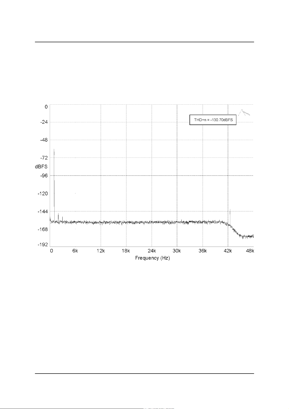
Prism Media Products Limited AD-2 Dual-rate A/D converter
Operation Manual
8. PERFORMANCE PLOTS
8.1. Dynamic Range
Figure 19 shows a Dynamic Range plot of the AD-2 in A-D mode sampling at 96kHz.
Figure 21: A-D mode Dynamic Range, at +28dBu sensitivity, 1kHz sine @ -60dBFS
Apart from its unrivalled dynamic range (measured as 130.70dB in the test above)
which ensures that the AD-2s noise lies well below that of any practical analogue
source, the AD-2 also has an exceptionally clean noise floor, free from spuriae and
interference components.
Issue 0.2 © Prism Media Products Limited
11 August 1998 Page 52 of 58
Page 53
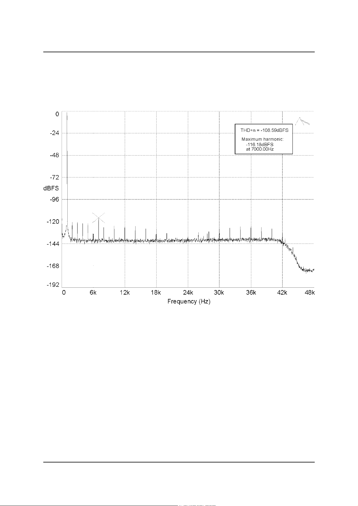
Prism Media Products Limited AD-2 Dual-rate A/D converter
Operation Manual
8.2. THD+n
Figure 20 shows a THD+n plot of the AD-2 in A-D mode sampling at 96kHz.
Figure 22: A-D mode THD+n, at +18dBu sensitivity, 1kHz sine @ -1dBFS
Although the -108.59dBFS full-scale THD+n figure is, in itself, state-of-the-art, the
absence of aharmonic spuriae gives the large-signal handling of AD-2 an entirely
analogue quality.
Issue 0.2 © Prism Media Products Limited
11 August 1998 Page 53 of 58
Page 54
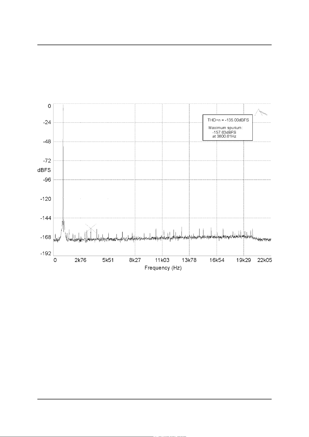
Prism Media Products Limited AD-2 Dual-rate A/D converter
Operation Manual
8.3. SRC (Sample-rate converter)
Figure 21 shows a THD+n plot of the AD-2 in D-D mode, sample-rate-converting a 24bit, 96kHz-sampled 1kHz full-scale sinewave to 44.1kHz sampling rate.
Figure 23: D-D SRC mode THD+n, 96kHz-to-44.1kHz, 1kHz sine @ 0dBFS
The largest spurious component in the test above is -157.63dBFS. This figure
represents a huge improvement over competitive asynchronous rate converters, whose
imprecise conversions produce large and obtrusive aharmonic distortion components;
these distortions have given sample-rate-converters their characteristic 'sound' in the
past.
Issue 0.2 © Prism Media Products Limited
11 August 1998 Page 54 of 58
Page 55
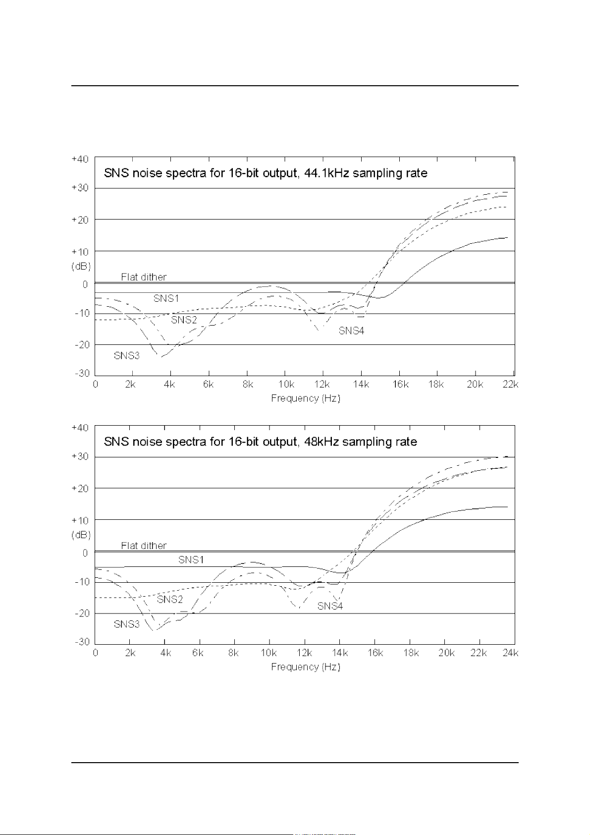
Prism Media Products Limited AD-2 Dual-rate A/D converter
Operation Manual
9. SNS NOISE SHAPER CHARACTERISTICS
Issue 0.2 © Prism Media Products Limited
11 August 1998 Page 55 of 58
Page 56
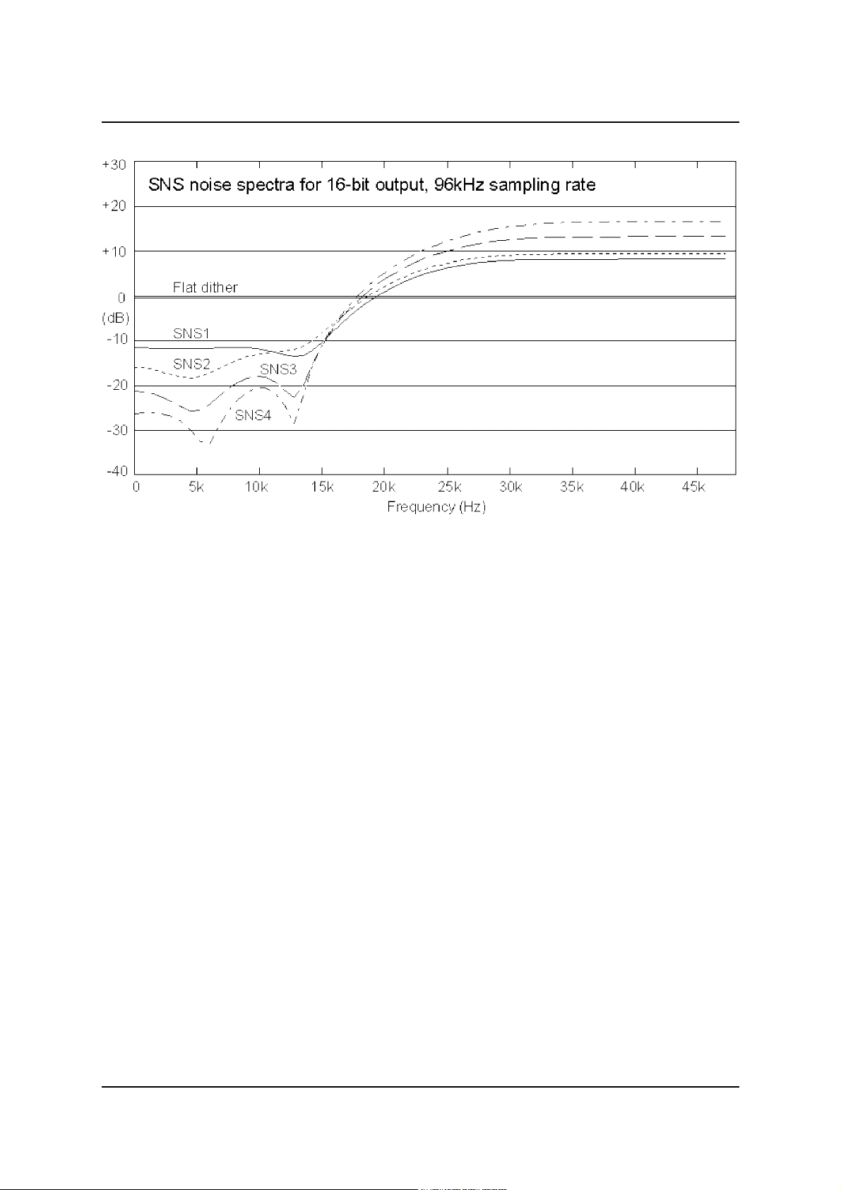
Prism Media Products Limited AD-2 Dual-rate A/D converter
Operation Manual
Issue 0.2 © Prism Media Products Limited
11 August 1998 Page 56 of 58
Page 57

Prism Media Products Limited AD-2 Dual-rate A/D converter
Operation Manual
10. ELECTROMAGNETIC COMPATIBILITY
This equipment is intended for use in an electromagnetically controlled environment. To
maintain the performance specification it should not be subject to strong magnetic
fields (such as in the immediate vicinity of a power amplifier or cathode ray tube) and all
connections should be terminated as described in the relevant sections of this manual.
This is also required to ensure that emissions are within applicable norms and that it
does not interfere with other equipment.
All coaxial connections should be made using a properly screened 75S cable with the
screen connected to the outer of the connector at both ends. All XLR connections
should use a screened twisted pair cable with the screen connected to pin 1 of the XLR
connector at both ends. In the case of the digital XLR connections this cable should be
of 110S impedance.
Issue 0.2 © Prism Media Products Limited
11 August 1998 Page 57 of 58
Page 58

Prism Media Products Limited AD-2 Dual-rate A/D converter
Operation Manual
11. REFERENCES
[1] AES3-1992 - ` Recommended Practice for Digital Audio Engineering - Serial Transmission Format for Two-Channel
[2] AES11-1991 - `AES Recommended Practice for Digital Audio Engineering - Synchronization of Digital Audio
[3] AES17-1991 - `AES Standard Method for Digital Audio Engineering - Measurement of Digital Audio Equipment' J.
[4] IEC958 - `Digital Audio Interface' International Electrotechnical Commission 1989
[5] Julian Dunn, Barry McKibben, Roger Taylor and Chris Travis - `Towards Common Specifications for Digital Audio
[6] Julian Dunn and Ian Dennis - `The Diagnosis and Solution of Jitter-Related Problems in Digital Audio Systems'
[7] AES-3id-1995 - `AES information document for digital audio engineering - Transmission of AES3 formatted data by
[8] Draft AES3-1992 Amendment 3-xxxx - Serial Transmission Format for Two-Channel Linearly Represented Digital
Linearly Represented Digital Audio Data' J. Audio Eng. Soc., Vol 40 No. 3, pp 147-165 (June 1992)
Equipment in Studio Operations' J. Audio Eng. Soc., Vol. 39 No. 3, pp 155-162 (March 1991)
Audio Eng. Soc., Vol. 39 No. 12, pp 961-975 (December 1991)
Interface Jitter' Preprint 3705, presented at the 95th AES Convention, New York, October 1993
Preprint 3868, presented at the 96th AES Convention, Amsterdam, February 1994.
unbalanced coaxial cable' J. Audio Eng. Soc., Vol. 43 No. 10, pp 827-844 (October 1995)
Audio Data' (still in preparation, July 1998)
FURTHER INFORMATION
Enquiries about this product should be addressed to :
Email : [email protected]
Web: http:\\www.prismsound.com
Prism Media Products Limited
William James House
Cowley Road
Cambridge
CB4 0WX
UK
Phone: +44-(0)1223-424988
Fax: +44-(0)1223-425023
Issue 0.2 © Prism Media Products Limited
11 August 1998 Page 58 of 58
Page 59

Prism Media Products Limited
William James House
Cowley Road
Cambridge
CB4 0WX UK
E-mail : [email protected]
Web : www.prismsound.com
Tel: +44 (0)1223 424988
Fax: +44 (0)1223 425023
 Loading...