

Prism Medical UK C450, C625 Owner's Manual
C450/ C625
Introduction ......................................................................2
Overview ..........................................................................2
Components of lift system ...............................................3
Component List ...............................................................4
Specifications ..................................................................4
List of Symbols and Contraindications…………………...6
Cautions ..........................................................................7
Attaching the airline to the lift ..........................................8
Operation
Turning the lift ON/OFF .............................................9
Raising/Lowering the carry bar ..................................10
Moving the lift along the track ....................................10
Moving the “H” system traversing beam ....................11
Return to Charge ............................................................12
Basics in transferring an individual ..................................13
Charging the lift ...............................................................16
Constant Charger ............................................................17
Attaching/Detaching QRS Carry Bar from QRS Hook ....18
LCD Display Functionality ..............................................20
Emergency Stopping .......................................................22
Emergency Lowering .......................................................22
Emergency Manual Raising or Lowering .........................23
Cleaning and Disinfection………………………………….24
List of applied Parts…………………………………………24
Trouble Shooting .............................................................25
General inspection and maintenance ..............................26
Lift Accessories ...............................................................28
IEC-60601-1-2:2007 EMC/EMI Compliance Guidelines..29
Service record history ......................................................33
Warranty ..........................................................................37
Owner’s Manual
Use and Car e
T rouble Shooting
Warranty Information
CAUTION: DO NOT ATTEMPT TO USE THIS EQUIPMENT
WITHOUT FIRST UNDERSTANDING THE CONTENTS OF
THIS MANUAL.
Introduction
Before using this equipment, and to ensure the safe operation of your C450/ C625 lift, carefully read this en-
tire manual, especially the section on “
Cautions”. The C450/ C625 is designed to be used in conjunction
with Prism Medical lift track, accessories and slings. Please refer to any user guides supplied with these components and refer to them while reviewing this manual.
Should any questions arise from reviewing this manual contact your local authorized Prism Medical dealer.
Failure to comply with warnings in this manual may result in injury to either the operator, or the individual
being lifted/transferred. Damage to the lift and/or related components may also occur. Be sure that the contents
of this manual are completely understood prior to using this piece of equipment.
Store this manual with the documents included with the lift system and sling (s). Contents of this manual are
subject to change without prior written notice.
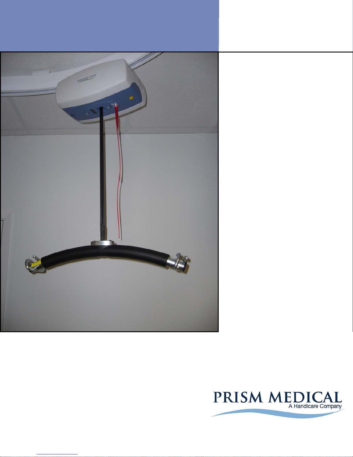
Overview of C450/ C625 lift system
The C450/ C625 is a lifting aid used by health care professionals and those providing care in the home to lift,
position and transfer clients or a disabled family member. The C450/ C625 lift is part of what is termed ceiling lift technology which takes advantage of lifting from above and not from below or the side. Additionally
the ceiling lift does not take up valuable floor space as most traditional methods do. Finally, the ceiling lift
makes it possible to move mobility impaired individuals with minimal strain or risk to the caregiver, while
providing complete safety, dignity and comfort for the client or family member.
The C450/ C625 lift is one of three major components that make up this technology. The other two components are the track and sling. The
ing structure of the institution, or home with the use of ceiling brackets. The track itself is made of specially
designed aluminum and comes in many different shapes, lengths and configurations, and is custom tailored and
installed to meet your specific requirements. The third component, the sling, is a specially designed fabric accessory that attaches to the lift by means of a carry bar and straps, and holds an individual while the lift, positioning or transfer takes place. Both the track and sling are generally supplied with the lift at the initial time of
purchase. Please refer to any user guides supplied with the
ing this manual.
The
C450/ C625 is a fixed ceiling lift, that is, it always remains on the lift track. It has the ability to lift an in-
dividual up from one location such as bed, move the individual along the track to another location and
finally lower the individual into a chair or bath. It is moved along the track in one of two ways. The first is by
manually moving the lift along the track with the aid of a caregiver. The second is by having the lift power itself along the track. The functions of lifting up or down, or moving to the left or right, are accomplished by
pressing buttons of a pneumatically (air) operated hand control. The hand control is attached to the lift by way
of a rubber airline tubing. Due to the design of the lift system, it takes very little effort to press a button to perform the desired motion.
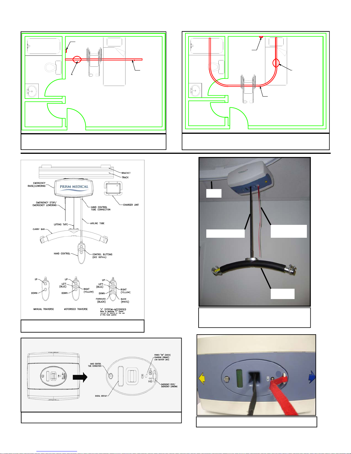
Please refer to figures 1A and 1B to see sample floor plans of an installed lift system. Refer to figures 2A and
2B to familiarize yourself with the components of the
view of the lift as it would be seen by an operator.
C450/ C625 lift runs on the lift track which is securely mounted to the ceil-
C450/ C625 lift and reference them while review-
C450/ C625 lift. Figures 3A and 3B show the underside
C450/ C625 - User Guide (753101) Rev: 14 MAR 2017 Page: 2
Components of lift system
CHARGER
BATH
BATH
CHARGER
TRACK
BATHROOM
LIFT
BED
BEDROOM
Figure 1A - Sample floor plan showing basic components of
a ceiling lift system.
LIFT
BATHROOM
BED
TRACK
BEDROOM
Figure 1B - Alternate sample floor plan showing basic
components of a ceiling lift system.
Track
Emergency Stop/
Lifting tape (strap)
Lowering
Figure 2A - Basic components of the ceiling lift
Figure 3A—Underside view of the lift
C450/ C625 - User Guide (753101) Rev: 14 MAR 2017 Page: 3
Carry bar
Figure 2B - The C450/ C625 ceiling lift with
standard Emergency Stop/ Lowering.
Figure 3B - Photo of underside
Component List
The following components are included with your new C450/ C625 lift system:
• C450/ C625 lift (Manual or Motorized traverse)
• Pneumatic Hand Control
• Lift Charger (mounted on the wall or ceiling at the end of the track)
• Owner’s Manual
• Warranty Card
SLINGS: If a sling has been supplied with the lift refer to the instructions included with the sling.
ACCESSORIES: If additional accessories such as a turntable, or gate system have been supplied with the lift
refer to the instructions included with those items.
IMPORTANT: Before initial use, the lift unit must be charged for 4 hours. Refer to section titled
"
Charging Instructions". The hand control airline tube must also be connected to the lift. If it is not
connected refer to the section titled “
Specifications of C450/ C625 lift
Lift Motor: 24 VDC
Traverse Motor: 24 VDC (Optional at time of Purchase)
“H” Frame Traverse Motor: 24 VDC (Optional at time of Purchase)
Charger Alternate 1 Model: Soneil, 2403SRM30
Charger Alternate 1 Input: 100-240 VAC, 1.5 Amps, 50-60 Hz
Charger Alternate 1 Output: 24 VDC, 1.5 Amps
Charger Alternate 2 Model: Soneil, 2403SRM20
Charger Alternate 2 Input: 100 VAC 0.45 Amps, 240 VAC 0.22 Amps, 50-60 Hz
Charger Alternate 2 Output: 28.8 VDC, 1 Amp
Charger Alternate 3 Model: Mascot, 9940
Charger Alternate 3 Input: 100-240 VAC, 0.9 Amps, 50-60 Hz
Charger Alternate 3 Output: 29.5 VDC, 1.3 Amps
Batteries: 24 VDC (2 x 12 VDC) 5.0 AH, Sealed Lead Acid
Lift Case: Flame Retardant ABS
Hand Control: Pneumatic
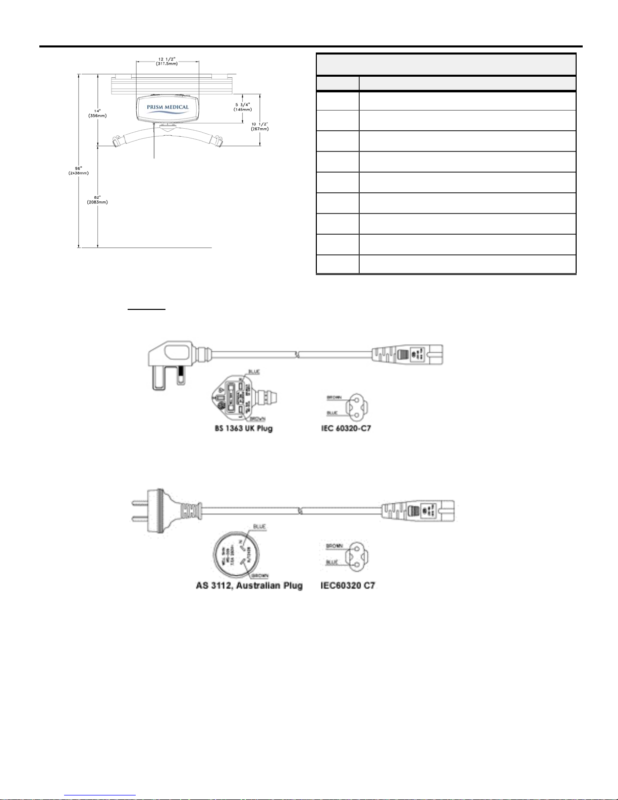
Lifting Range: Up to 96” (2438mm)
Lift Weight: 21—23.5 lbs.(9.5-10.65Kg)
Maximum Load: Standard maximum load 450lbs (204 Kgs). Also available in 625 lbs(283 Kgs).
Duty Cycle: 1 Min “ON”-9 Mins “OFF”
Rated Performance: 30-40 lifts at 625 lbs.(283 Kgs) , 50-60 lifts at 450 lbs.(204 Kgs) , 1 Min “ON”-9 Mins
Max Sound Level: Raising Max load 56.1 dB , Lowering Max load 60.3 dB .
Service Life: 22500 Cycles or 10 years , whichever comes earlier.
As a precautionary measure, the lifting strap should be replaced every 5000 cycles or 3
years, whichever comes earlier. Higher usage lifts may necessitate more frequent
replacement of the lifting strap; please refer to pages 26-27 for General Inspection and
Maintenance information.
Connecting airline to the lift”.
Shipping/Storage Conditions:
Temperature: -40 to +70 ºC
Relative Humidity: 10 to 100% RH
Atmospheric Pressure: 500 to 1060 hPa
Maximum load of the installed lift is
determined by referring to the product
label located on side of lift.
“OFF” duty cycle, each lift being 24 inches/610mm at the middle of the lifting range
(from 54”/1370mm strap out to 30”/762mm strap out) per full battery. Please note: the
lift has a break in period; breaking in of the lift will need to be done before these
numbers will be achieved. The breaking in period will vary from lift to lift and is
dependent on the frequency of use and the types of load being applied, the higher the
load and a greater frequency of use will break in the lift faster.
C450/ C625 - User Guide (753101) Rev: 14 MAR 2017 Page: 4
Code Description
323100 C450 Manual Traverse
323117 C625 Manual Traverse
323150 C450 Power Traverse
323127 C625 Power Traverse
Models Table for C450/ C625 Lift
Lifting Range
323177 C450 Power X-Y
323137 C625 Power X-Y
323149 C450 Power Traverse c/w Return to Charge
323126 C625 Power Traverse c/w Return to Charge
NOTE: For C Series w/QRS Hook Part nos., See page no. 18
NOTES:
Please use the following type of plug for C-450 or C-625 lifts installed in the
UK:
Please use the following type of plug for C-450 or C-625 lifts installed in Australia.
The C-450 or c-625 lift shall be connected to a center-tapped single phase supply cir-
cuit when users in the United States connect the equipment to a 240 V supply system.
IMPORTANT: Refer to section “IEC-60601-2-7:2007 EMC/EMI compliance Guidelines” for details
regarding electromagnetic compatibility information .
C450/ C625 - User Guide (753101) Rev: 14 MAR 2017 Page: 5
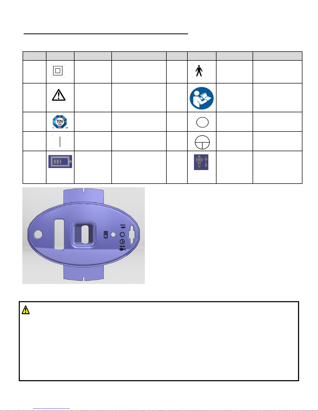
Glossary of Symbols used in the C Series
Mark Symbol Reference Title Mark Symbol Reference Title
X
IEC 604175172
C
LASS II equipment X
IEC 604175840
TYPE B APPLIED
PART
X
X
X
X
ISO 70000434
TUV Certified by TUV
IEC 604175007
NA
Caution risk of danger or Attention, consult ACCOMPANYING
D
OCUMENTS
“ON” POWER
STATUS LED’s FOR
BATTERY LEVEL
AND SYSTEM ERROR
INDICATION
X
X
X
X
ISO 7010M002
IEC 604175008
IEC 604175011
NA
EFER TO INSTRUC-
R
MANUAL/
TIONS
BOOKLET
“OFF” POWER
“ON”/”OFF”
EMERGENCY
DOWN
PICTORIAL REPRESENTATION OF SYMBOLS
Contraindications
There are no known “contraindications” associated with the usage of C450/C625 and its accessories,
provided they are used a per manufacturer’s recommendations and guidelines.
However ,it is recommended that a client specific assessment is completed by a trained and knowledgeable
health care professional to determine the method of transfer. Prism Medical does not recommend a required
number of caregivers for the use of our products. This information and recommendation can only be provided
after a thorough personalized, case specific assessment, as there are many factors that can influence these decisions. It is however, “obligatory” that a client that is assessed as being an independent user of our ceiling
lift technology have the ability to receive assistance, during the transfer, in the event of a lift malfunction or
personal concern. This assistance can be provided in the form of; a nearby qualified caregiver, a phone, a
communication device etc.
C450/ C625 - User Guide (753101) Rev: 14 MAR 2017 Page: 6

Cautions
● The C450/ C625 must be installed prior to use. Contact your local authorized dealer to ensure that it
is properly installed. The C450/ C625 must be installed only by persons authorized by Prism
Medical. The installation guide is available with authorized dealers.
● Under no circumstance should the C450/ C625 track, lift and sling (s) or entire system be put in con-
trol of a person who has not been properly trained in the use and care of this equipment. Failure to ad
here to this warning may result in serious injury to the operator, and/or the individual being lifted/
transferred.
● The C450/ C625 lift, and associated track and sling (s) are not toys. Do not use it for unsafe prac-
tices. Do not allow children to play with the lift or any of its’ components.
● The manufacturer's warranty is void if persons unauthorized by Prism Medical perform work on the
C450/C625 lift system.
● There are no user serviceable parts inside the cover. Do not remove cover screws, or open the lift
unit, as this may result in serious injury and will VOID THE WARRANTY.
● In facilities where more than one operator will be responsible for using the C450/ C625 lift and as-
sociated track and sling (s) it is imperative that all such members be trained in its’ proper use. A train ing program should be established by the facility to acquaint new operators with this equipment.
● Never expose the C450/ C625 lift directly to water. Warranty does not cover any misuse or abuse of
the lift system.
● To maintain optimum function, the C450/ C625 should be inspected and maintained on a regular
basis. See the section titled “General Inspection and Maintenance”.
● Any accessories used with the C450/ C625 including track and sling (s), should be checked to
ensure that they are in good working order. Check for signs of wear or fraying prior to use. Report any
unusual wear, or damage immediately to your local authorized Prism Medical dealer.
● The C450/ C625 lift and associated lift, track and sling (s) are intended only for lifting and
transferring of a person. Prism Medical will not be responsible for any damage caused by the misuse,
neglect or purposeful destruction of the lift, and/or its’ associated components. Do not attempt to
modify/alter the C-625/C-450 lifts.
● Do not in any circumstance exceed the maximum allowable load of this lift. Refer to the
Specifications” section of this manual, and/or the labels on the side of the lift.
“
● The installation of the lift, track, accessories, and sling are certified to a maximum load. Do not
exceed the maximum rated load of any of the components,
● There is a risk of explosion if the lift is used in the presense of flammable anaesthetics.
● Ensure that a clear space is maintained around the lift and track. Move all curtain material and other
obstacles out of the way before performing a transfer.
The charger must be located outside the patient vicinity at all times. The patient vicinity is the space
with surfaces likely contacted by the patient or an attendant who can touch the patient. This
space is 6 feet (1.83m) beyond the perimeter of the bed, examination table, etc., extending vertically
7-1/2 feet (2.29m) above the floor.
C-625/C-450 lifts can be decommissioned/Disposed off after recommended service life in accordance
with regional component specific disposal recommendations.
C450/ C625 - User Guide (753101) Rev: 14 MAR 2017 Page: 7

Attaching the airline tube to the lift
Caution: A sturdy ladder may be required in order to access the underside of the lift to re-attach
the rubber airline of the lift. Caution should be used when this is required.
Should you have any concerns or questions contact your local authorized Prism Medical dealer.
Should the gray rubber airline that connects the lift to the hand
control become disengaged from the underside of the lift it must
be re-connected in order for the lift to work properly.
The rubber airline may become disconnected for the following
reasons:
1) The lift is pulled along the track by the airline.
2) The tubing accidentally gets wrapped around an object while
Figure 13A - Grey rubber grommet located on
underside of lift. Rubber airline is not connected.
Metal pins that get inserted into the holes
of the grommet of the lift.
Figure 13B - Grey rubber airline being inserted
into rubber grommet of lift. The metal ribbed
pins are on the airline.
Pieces connected together
Figure 13C - Gray rubber airline being inserted
into rubber grommet of lift. The grey ribs on
both pieces are lined up. The metal ribbed pins
are on the airline.
C450/ C625 - User Guide (753101) Rev: 14 MAR 2017 Page: 8
a lift or transfer is being performed.
3) It is accidentally pulled out by the caregiver or the individual
being lifted.
The airline is connected to a grey rubber grommet located on the
underside of the lift. Refer to figure 13A.
Small metal ribbed pins located at the end of the airline hold the
airline to this rubber grommet in a specific manner. Therefore it is
important to make sure that the airline is connected properly.
Both the grey airline and the rubber grommet have a grey rib on
one of their sides. Line up the grey ribs together. Refer to figure
13B. When this is done then the metal ribbed pins attached to the
end of the airline can be re-inserted into the corresponding holes
in the rubber grommet on the underside of the lift. Be sure to insert the pins into the grey rubber grommet sufficiently so that it is
secure. Refer to figure 13C.
Perform a brief test to ensure proper connectivity. Turn the lift
ON and OFF. Raise and lower the carry bar. For motorized traverse lifts move the lift left and then right. If these functions work
correctly then the airline is properly connected.
If the lift does not work properly, check to ensure that the grey
ribs on the grey rubber grommet on the underside of the lift and
the airline tubing are lined up properly. If they are not lined up
properly, then remove the airline, line up the grey lines and then
re-insert it into the rubber grommet. Perform the test as noted in
the preceding paragraph. If there are still problems with the lift
then contact your local authorized dealer for service.
Operation
Caution: Always, before using the C450/ C625 lift system, the lift, track and
sling (s) must be visually checked for any unusual wear, or damage. Refer to the user
manual with each piece of supplied equipment to determine what should be checked.
Should anything look unusual contact your local Prism Medical dealer prior to use.
Failure to comply with this caution could result in serious injury to the operator, the individual being lifted and/or damage to the lift.
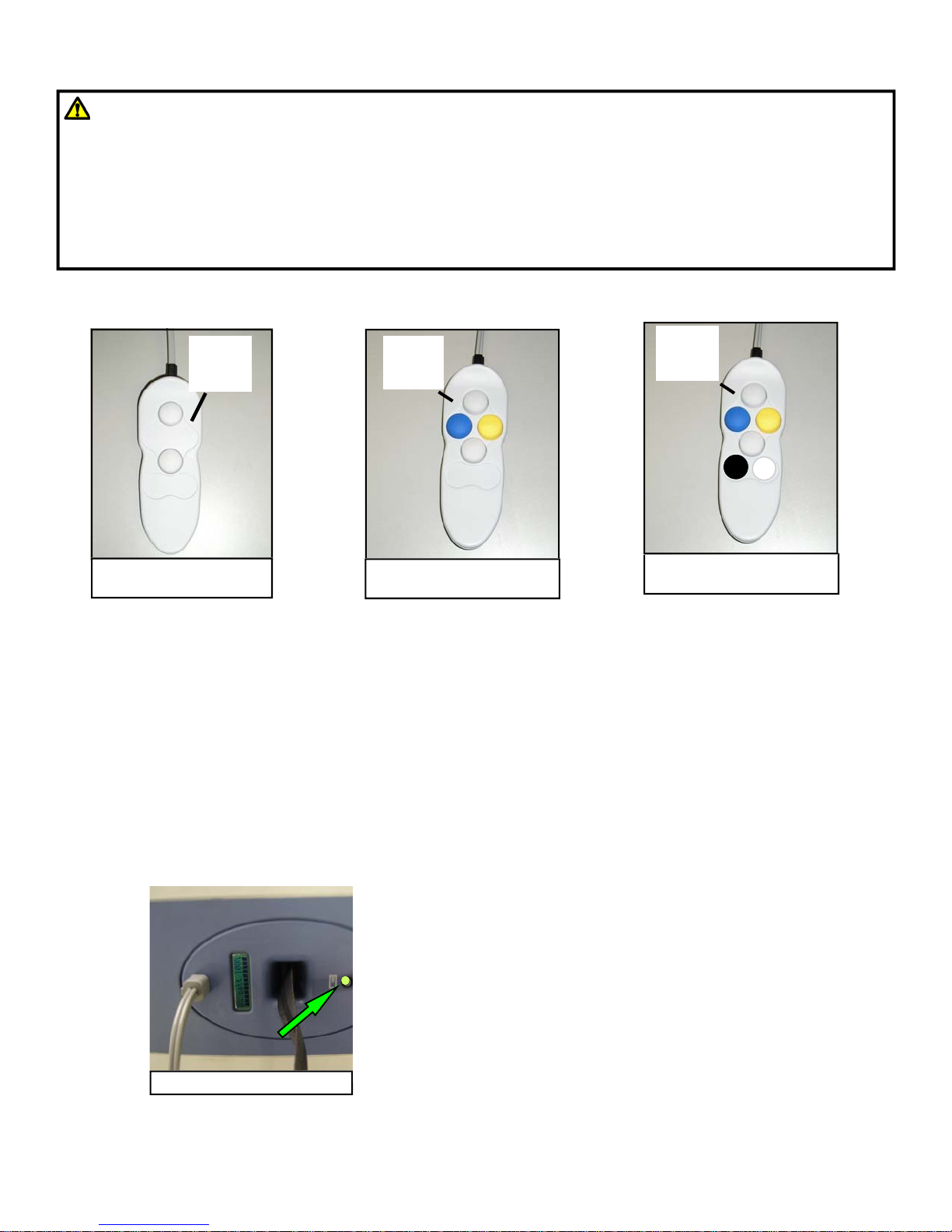
Turning the lift ON/OFF
Press any
button to
turn ON
Figure 4A - Manual traverse hand
control
Press any
button to
turn ON
Figure 4B - Power traverse hand
control
Press any
button to
turn ON
Figure 4C - Motorized traverse “H”
system hand control
NEW LIFTS OR LIFTS THAT HAVE HAD BATTERIES CHANGED SHOULD BE CHARGED A MINIMUM OF 30
MINUTES BEFORE USE.
Refer to figures 4A, 4B and 4C to determine the hand control that is attached to the lift.
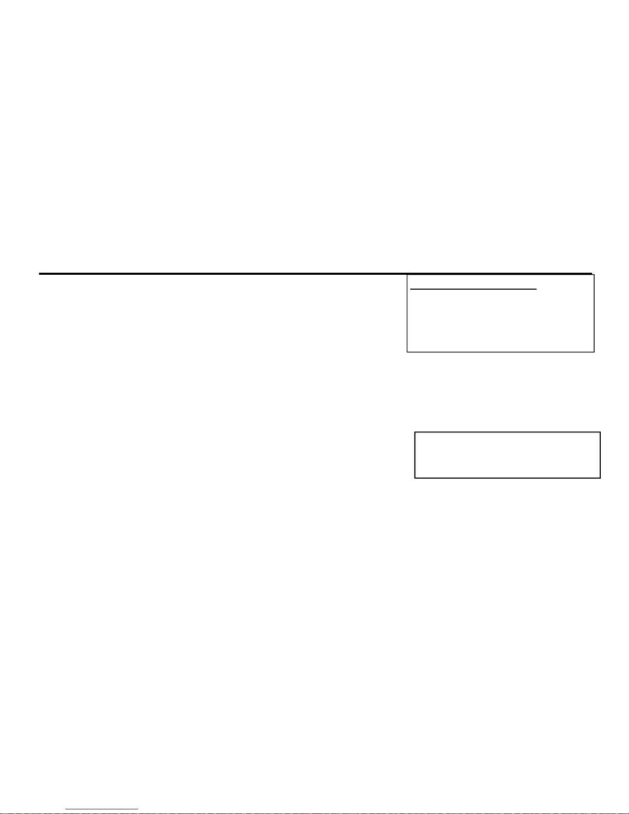
To operate the lift it must first be turned ON with the use of the hand control. This can be done by pressing any button
on the hand control. The indicator light located on the underside of the lift will turn GREEN and the display screen will
turn on. Refer to Figure 4D. If the lift fails to turn ON at anytime, ensure that the EMERGENCY STOP/ LOWERING
CORD has not been pulled and that the plastic clip at the end of the red cord has not come out.
To conserve battery power the lift will automatically shut off after approximately 5 seconds if no buttons are pressed after
initial “waking” or after approximately 2 minutes on non-use after last button push.
Figure 4D - Lift ON indicator
C450/ C625 - User Guide (753101) Rev: 14 MAR 2017 Page: 9
Figure 4E - Low battery indicator
hand control
Operation
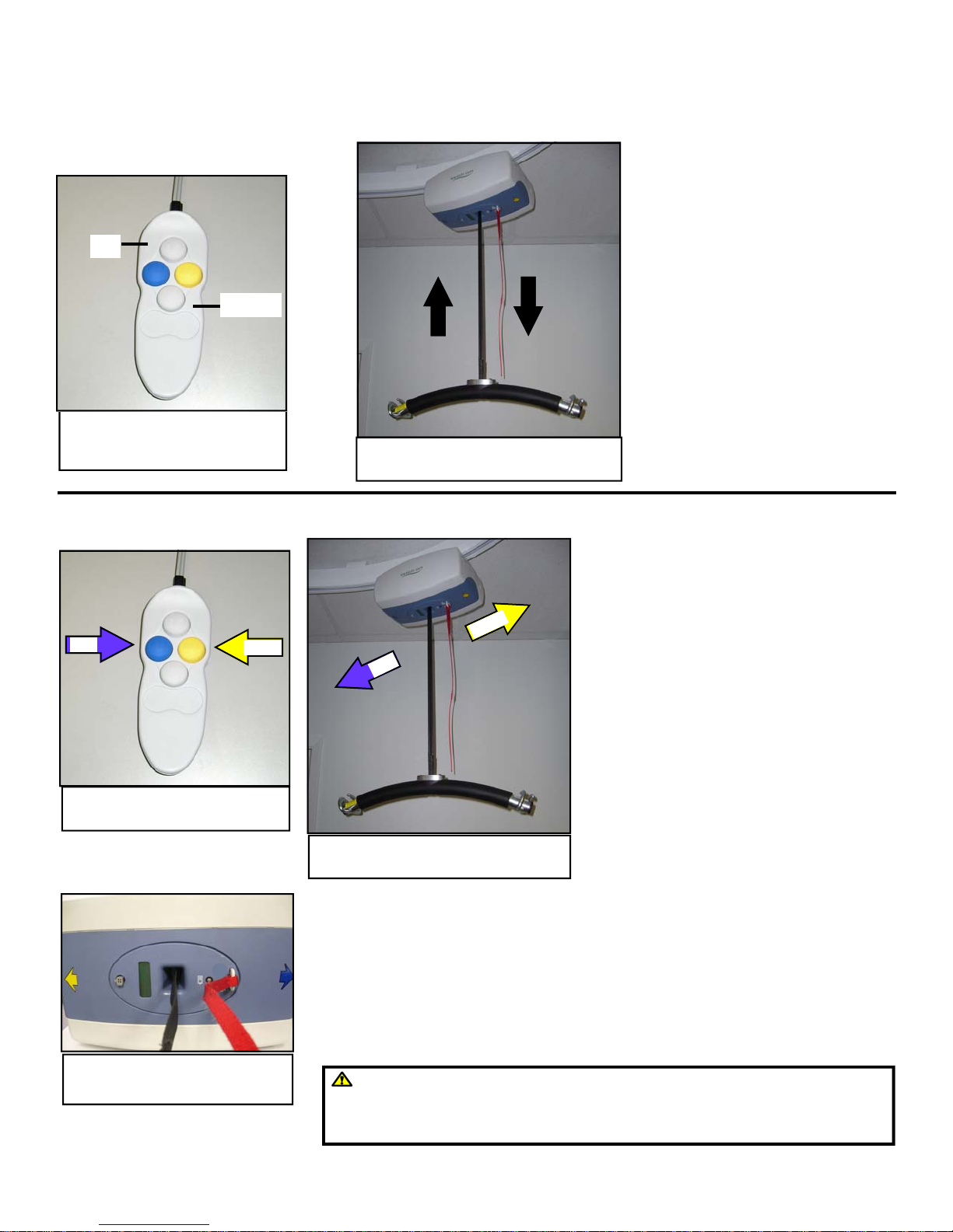
Raising/lowering the carry bar
UP
DOWN
Figure 5A - Power traverse hand control showing raising/lowering functions
Figure 5B - Lift showing raising/lowering of
carry bar.
Moving the lift along the track
By pressing the DOWN arrow
button, or the UP arrow button,
the carry bar can be lowered/
raised to the correct height for
attaching the sling or positioning an individual. Refer to figure 5A and 5B
It is recommended that the caregiver (operator) hold the carry
bar with one hand while this is
being done so that it will not
accidentally sway and/or come
into contact with an individual
or close object. These buttons
work the same on each model
of the lift.
BLUE
Figure 6A - Motorized traverse hand
control showing colored buttons.
YELLOW
Figure 6C - Directional arrows on
underside of lift
The lift is normally parked at the charging station end of the track when not in
W
O
L
L
E
Y
use. It can be moved along the track to a
position directly above the person to be
E
U
L
B
lifted in one of two ways.
If you have a manually traversing lift
lower the carry bar to a comfortable
height such that it can be easily grabbed
by your hand. Move the lift along the
track by gently pushing the carry bar, or
individual in the sling. Never pull the
lift along the track.
Figure 6B - Lift showing horizontal movement. Arrows are for motorized versions
If you have a motorized traversing lift, use the blue or yellow colored
directional hand control buttons to move the lift. The blue and yellow
buttons correspond to the blue and yellow directional arrows on the underside of the lift. The direction therefore that is taken is determined by
the color of the button that is pressed. This works the same no matter
what side of the lift a person is standing on.
Refer to figures 6A, 6B and
6C.
Caution: Always use extreme care when moving the lift along the
track. Watch out for and avoid any obstructions that may cause injury
to the individual in the sling and/or damage to the lift.
C450/ C625 - User Guide (753101) Rev: 14 MAR 2017 Page: 10

Operation
Moving the “H” system traversing beam
If the installed track is an “H” system then this sec-
BATH
BED
TRAVERSING
BEAM
tion should be reviewed as it describes how to move
the traversing beam. If the installed track is not an
“H” system then this section can be skipped.
The “H” system involves the installation of two par-
BATHROOM
LIFT
allel support tracks and one traversing beam that is
mounted perpendicular to the two support tracks.
Refer to figure 7A. The benefit of this type of system
SUPPORT
TRACK
(BOTH SIDES)
BEDROOM
CHARGING
LOCATION
CHARGER
is that it provides greater movement and positioning
ability for an individual since the floor space coverage area is much higher than for a single piece of
track.
Besides the previously described UP/DOWN move-
Figure 7A - Sample of “H” system room covering layout. Note that the
lift can be moved along the traversing beam, and that the traversing
beam itself can be moved along the two parallel support tracks.
The actual direction of travel when the hand control buttons are pressed
may be different than shown, since the track and lift orientation may be
different than installed. .
ment of the carry bar, and LEFT/RIGHT movement
of the lift, the “H” system adds the ability to move
the traversing beam anywhere along the length of
the two parallel support tracks. Refer to figure 7A.
This can be accomplished in one of
two ways. If the installed “H” traversing beam is
manually traversing then the
beam is moved along the support
tracks by manually moving the
beam, lift, and individual in one motion. This movement is the same as
that used for a manual traversing
lift, as previously described.
If the installed “H” system traversing beam is motorized traversing
then the beam is moved along the
support tracks by pressing either the
Figure 7B - Power traverse “H”
system hand control showing
traversing beam movement
buttons. Button colors correspond to the black and white
directional arrows located on the
underside of the lift.
Figure 7C - Directional arrows on underside of power
traverse “H” system lift. Black and white arrows show
traversing beam direction of travel when the corresponding colored button is pressed on the hand control.
black or white hand control button. Refer to figure 7B. This will move the beam
in the direction of travel as noted by the black [▼] and white arrows [▲]located
on the underside of the lift. Refer to figure 7C.
Caution: Always use extreme care when moving the traversing beam. Watch out for and
avoid any obstructions that may cause injury to the individual in the sling, or damage to the lift/
Caution: Do not operate the lift , with bottom cover open.
C450/ C625 - User Guide (753101) Rev: 14 MAR 2017 Page: 11
 Loading...