

Page 1

Masking System
Cinomask F-100
A Picture to
Remember
Assembly Instructions
INSTALLATION INSTRUCTIONS
Carefully remove and unwrap all t he contents of box. Referring to the parts list, make
sure you have everything needed to proceed with the installation of the masking
system. If any parts are missing, contac t Prismasonic immediately.
Inspect the parts to make sure there are no shipping defects. If you notice a problem
with the item itself, or the screen’s mechanical system, contact Prismasonic
immediately.
Part List:
Wooden Assemblies
Framewo rk Bar (6 pcs)
Aluminum Brackets
Extension Bracket (2 pcs)
Frame Holder M (18 pcs)
Wall M ount (2 pcs)
Wall M ount Side (4 pcs)
Wall Socket, 16 mm (8 pcs)
Hardware
Cap Screw, M4 x 35 (8 pcs)
Cap Screw, M5 x 16 (8 pcs)
Cap Screw, M5 x 30 (10 pcs)
Cap Screw, M6 x 12 (8 pcs)
Cap Screw, M6 x 16 (4 pcs)
Cap Screw cle ar, M6 x 20 (18 pcs)
Cap Screw, M8 x 16 (4 pcs)
Set Screw, M8 x 6 (4 pcs)
Tor x S cre w, black (12 pcs)
Tor x S cre w, clear (4 pcs)
Tools & Misc.
L-wrench, 3 mm (Do not exist if ordered with a scre en)
L-wrench, 4 mm (Do not exist if ordered with a scre en)
L-wrench, 5 mm
Torx Driver (Do not exist if ordered with a sc reen)
Screw Driver
Velvet Stickers (4 pcs)
Electrical Parts
Power Cor d
Power Con verter
Remote Controller
----------------------------------------------------
Page 2
Masking System
Cinomask F-100
Assembly Instructions
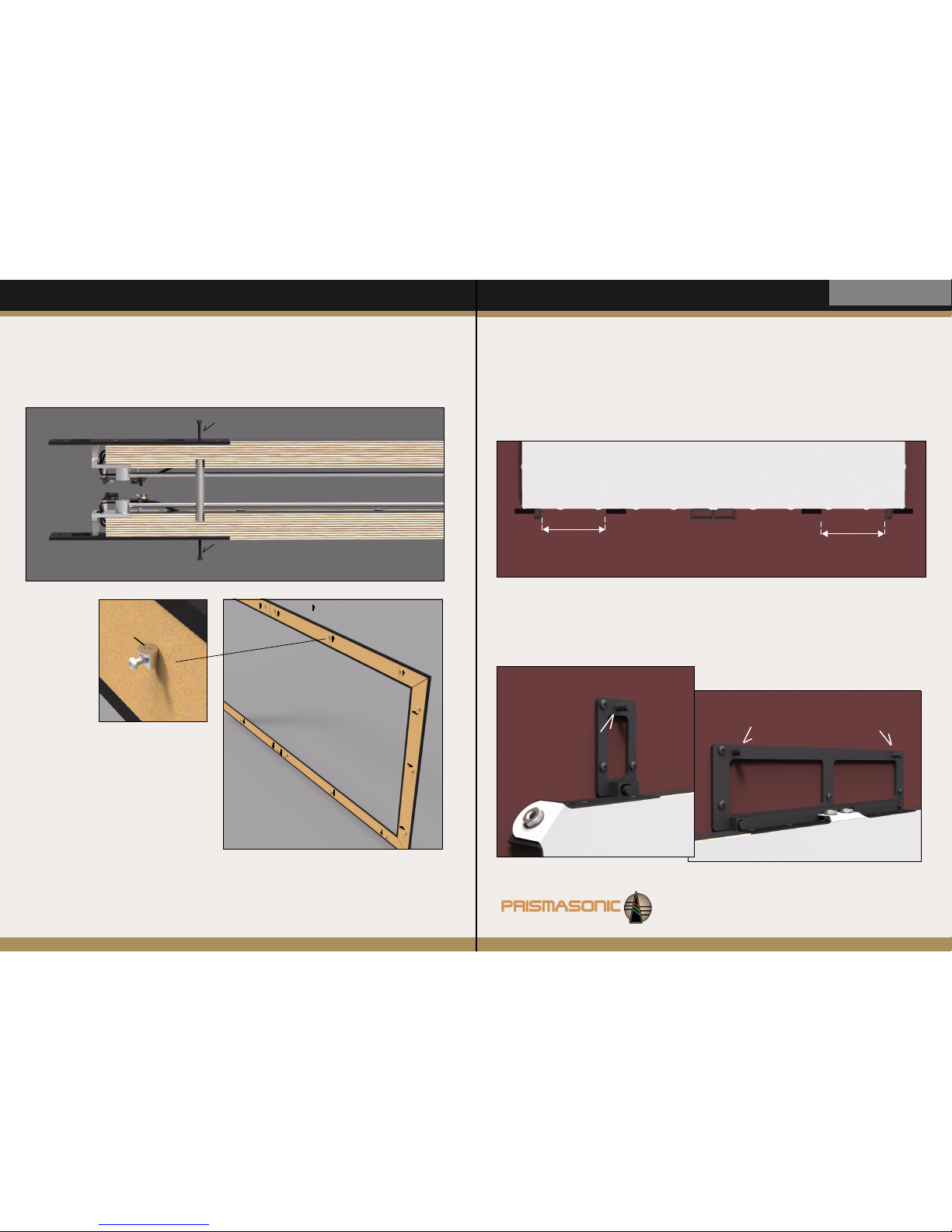
STEP 3
First attach the four velvet stickers exactly as presented in Fig 3. All four
stickers are in line right below the bottom horizontal screen framework bar.
The stickers at corners are also in contact with the side wall plates, while the
center ones are separated from the plates with a distance as informed in a
picture. The stickers are for preventing the parasitic reflections of optoelectrical transmitters of mask travel detection from wall to system, thus
making the performance 100% reliable with all wall materials.
635 mm : 156”
526 mm : 136”
421 mm : 116”
635 mm : 156”
526 mm : 136”
421 mm : 116”
Fig 3
STEP 4
Now attach the total eight wall Socke ts to remaining screw holes of every four Wall Plate S (Fig 4a) and both
two Wall Plate (Fig 4b). Tighten the sockets securely and make sure the heels of sockets come in contact with
the plates.
Fig 4b
Fig 4a
Assembly Instructions:
STEP 2
If you are upgrading the Cinoscreen F-100 / FAT100, remove the Velve t Fram es from the
Cinoscreen while it is hanging on the wall. Also
remove all the existing Frame H olders from the
back side of frames and replace them with Frame
Holder M parts. By using Cap Screws, clear m6 x
20, prepare to attach the new holders to frames
exactly as shown in Fig 2. Tighten the screws
securely using L-wrench, 4 mm.
In the horizontal frames the screw holes of new
frame holders are pointing from center to side,
whilst in the vertical frames only the holder in the
middle is pointing from center to side, and the two
others in side are pointing from side to center.
STEP 1
First unpack the items from shipping tubes and boxes. As shown with an arrows in Fig 1,
remove the two delivery bars from each horizontal and vertical Framework Bars, which
connect the two bars to each other. Use L-Wrench, 3 mm for the screws to release the
bars.
screw hole
Fig 2
= Direction to where the screw hole
of part is pointing
Fig 1
Page 3

STEP 6
Now attach the top-right Framework Bar (Fig 6). First string the Wall Mount Side to Wall socket after which
connect the other end to extension Bracket by three To rx Sc rew s, 5 x 35. Tighten the screws securely using
Tor x D riv er
. Also now screw the Set Screw, m6 x 8 to the screw hole at location Fi g 5e to an extent which
prevents the bar falling from the Wall Socket.
Finally do the same procedure as mirror image for the bottom horizontal framework bars, which are much
similar to the upper bars except for the electrical control boards and wiring they include.
Fig 6
Fig 5
c)
STEP 5
Starting from the horizontal Framework Bar at top-left, f irst attach the Wall Mo unt to Extension Bracket by
using two Cap Screws, m6 x 16 (Fig 5a). Next using three Tor x S cre w, black connect the Extension Bracket to
the slot of framework bar (Fig 5b). After this, by using Tor x sc re w, clear attach Wall Mount Side to the pre
assembled corner bracket as shown in Fig 5 c. Finally string the wall mounts to Wall Socke ts of Wall Plates,
exactly as shown in Fig 5. By using L-Wrench, 4 mm insert and tighten the Set Screw, m6 x 8 in the screw hole
at location d) to an extent which prevents the bar falling from the socket.
NOTE! The pre assembled bars, which are assembled in top can be identified not including the electrical control
boards on them.
d)
e)
a)
a)
b)
Assembly Instructions
Masking System
Cinomask F-100
Fig 7
STEP 7
To finalize the masking framework assembly, attach the two vertica
framework bar assemblies to the horizontal bars (Fig 7). In every
four corner use Cap Screw, m8 x 16 (marked with a) in close up),
and two Cap Screws, m5 x 16 (marked with b) in close up). Tighte
n
the screws securely using L-Wrench, 5 mm and L-Wrench, 4 mm.
Make sure that after installation the loosen wire ends of both
vertical bar assemblies are locating in bottom corners, so that
they can be further connected to the m otor control boards.
STEP 8
Attach the connector ends on left-bottom toget her as shown in Fig 8a.
Make sure the parts snap securely to each other. Now connect the
power for the first time to the socket, marked by b) in Fig 8. There is an
extra notch on a framework slot under the aluminum bracket (Fig 8c) to
offer enough space to feed the DC plug into the socket.
Fig 8
a)
b)
Bottom view
c)
Page 4

STEP 9
By pressing (and holding) the ‘CLOSE’
button of Remote Controller (pointing it to
the receiver board) (Fig 9a), and
simultaneously pulling the left mask from
the velvet bar, drive the mask fabric close
until the bar reaches the sliding brackets in
top and bottom (Fig 9). Prepare to attach
the mask bar to both upper and lower slide
brackets using Cap Screws, m6 x 12
(marked by
b in a close up). Tighten the four
screws securely with L-Wrench, 4 mm.
Now push the yellow switches of two
detector boards, which are locating on the
bottom-left framework bar marked by c) in
Fig 9, to ‘ON’ position. After this the left
side mask is not reacting to remote
controller until the velvet frames have
been installed in STEP 12 and 13.
a)
c)
Fig 9
b)
Assembly Instructions
Masking System
Cinomask F-100
STEP 11
Redo the STEP 8 and STEP 9 exactly similarly
now to the right side of screen. Again make sure
the yellow switc hes of two detector boards on
the right part of screen becomes to ‘ON’ position
after performing the steps.
STEP 10
Connect the loosen wire ends of ‘right- bottom’ framework bar to the receiver board (Fig 10 and Fig 9a).
Make sure the connectors snap securely to each other.
Fig 10
STEP 12
Starting from left vertical Ve lvet Fra me, attach the frame to the vertical f ramework bar only from center
holder of frame. String the Cap Screw m5 x 30 through the hole and using L-wrench 4mm tighten the
screw securely against the frame holder exactly as shown in Fig 12a (velvet frame is drawn transparent in
a close up pictures). Similarly, only from center, attach the upper left horizontal fram e to the horizontal
framework bar (Fig 12b). There are three slots in the horizontal framework bar to where the frame
holders are inserted before the screw can be tightened against the holder thread.
In corner the two Cap Screws,
m4 x 35 are used for pushing
the elastic joint of corner
seamlessly together (Fig 12c).
Before tightening, the frame
ends in corner are first
adjusted by hand to match
each other. By using the L-
wrench, 3mm, tighten the
screws to an extent that the
velvet joint becomes firmly
together.
c)
c)
b)
a)
Fig 12
Page 5

Assembly Instructions
Masking System
Cinomask F-100
Yo u a re d on e! Enjoy your new 2.40:1 setup. In the use, the aspect ratios between the
terminal stops are adjusted simply by releasing the control button to match the
aspect ratio of each media.
----------------------------------- -----------------------------------------------------------
STEP 13
Exactly similarly attach the right side velvet frames to framework. The elastic joint of left and right horizontal
frames have been designed to be tight. After matching the frame ends by hand (as instructed in a tip below), the
parallel positions with each other can be fine tuned by the two Cap Screws m5 x 30 (Fig 13a), which are pushing
the both frame ends upwards. Finally attach the lower horizontal frames to their places. Still remove the cover
sheet from the circ ular IR window of left bottom fr ame. The screen with the masking system is now ready for the
use.
TIP! A tight center joint of horizontal frames can be connected together without difficulty by pulling the both center
ends away from framework bars until they match to each other, after which they can be released to go back down
against the framework (Fig 13b). Before doing this the both frames must have been attached from center to the
framework bars (Fig 12b).
Fig 13
a)
b)
Top vie w
STEP 14
Now power the system up from either left or right side motor control board (Fig 8b and Fig 14). By pressing and
holding the ‘OPEN’ button of remote controller, drive the masks to full open (2.40:1) position. The opto electrical
sensors stop the masks automatically after they disappear under the main velvet frames. After this drive the masks
to full close (1.33:1) position, where they again auto matically stop. If the side mask travels from open to close are
not quite synchronous to each other, their speed can be further adjusted. This is done with Screw Driver by
opening (~5-10 rounds to counter clock wise) the trimmer screw of mo tor control board marked by a) in Fig 14,
but only at the side which was moving slower. The iterative tuning back and forth can be performed to find the
perfect synchrony.
Similarly the calibration can be done to the close to open movement. Now, however, the trimmer screw marked
by b) in Fig 14 is closed (~3-5 rounds to clock wise) at the side which was moving faster. And again the iterative
tuning back and forth can be operated to find the synchrony.
NOTE! The system is good to be powered down while adjusting the trimmer screws with screw driver
a)
b)
left side board
Fig 14
a)
b)
right side board
Masks have been driven to full open 2.40:1 position
 Loading...