

Prioris ZX 6000MP SERIES User Manual
PRIORIS ZX
6000 MP SERIES
USER’S GUIDE

Prioris ZX 6000MP Series
User’s Guide
Part Number: ER-930WW-UA. A01
Digital Equipment Corporation

July 1996
The information in this document is subject to change without notice and
should not be construed as a commitment by Digital Equipment
Corporation.
Digital Equipment Corporation assumes no responsibility for any errors
that might appear in this document.
The software, if any, described in this document is furnished under a
license and may be used or copied only in accordance with the terms of
such license. No responsibility is assumed for the use or reliability of
software or equipment that is not supplied by Digital Equipment
Corporation or its affiliated companies.
Restricted Rights: Use, duplication, or disclosure by the U.S. Government
is subject to restrictions as set forth in subparagraph (c) (1) (ii) of the
Rights in Technical Data and Computer Software clause at DFARS
252.227-7013.
Prioris ZX 6000MP Series User's Guide
Copyright Digital Equipment Corporation.
All Rights Reserved.
DEC, Prioris, ServerWORKS, and the Digital logo are trademarks of Digital
Equipment Corporation.
Banyan and VINES are registered trademarks of Banyan System Inc.
Intel, OverDrive, and Pentium are registered trademarks of Intel
Corporation.
Logitech is a trademark of LOGITECH, Inc.
Microsoft, MS-DOS, MS OS/2, Windows NT, Windows 95, and Windows
for Workgroups are registered trademarks of Microsoft Corporation.
NeXT is a registered trademark of NeXT, Inc.
Novell and NetWare are U.S. registered trademarks of Novell Inc.
OS/2 and PS/2 are registered trademarks of International Business
Machines Corporation.
PhoenixBIOS is a trademark of Phoenix Technologies Ltd.
SCO UNIX is a trademark of The Santa Cruz Operation, Inc.
SCSI
Select
is a registered trademark of Adaptec Corporation.
SIMM is a registered trademark of Wang Laboratories.
All other trademarks and registered trademarks are the property of their
respective holders.

FCC ID: A09-930WW
The FCC wants you to know...
This equipment has been tested and found to comply with the limits for a
Class B digital device, pursuant to Part 15 of the FCC rules. These limits
are designed to provide reasonable protection against harmful
interference in a residential installation.
Any changes or modifications made to this equipment may void the user's
authority to operate this equipment.
This equipment generates, uses, and can radiate radio frequency energy
and, if not installed and used in accordance with the instructions, may
cause harmful interference to radio communications. However, there is no
guarantee that interference will not occur in a particular installation. If this
equipment does cause harmful interference to radio or television
reception, which can be determined by turning the equipment off and on,
the user is encouraged to try to correct the interference by one or more of
the following measures:
• Reorient or relocate the receiving antenna
• Increase the separation between the equipment and receiver
• Connect the equipment into an outlet on a circuit different from that
to which the receiver is connected
• Consult the dealer or an experienced radio/TV technician for help
All external cables connecting to this basic unit need to be shielded. For
cables connecting to option cards, see the option manual or installation
instructions.
This digital apparatus does not exceed the Class B limits for radio noise
emissions set out in the radio interference regulations of the Canadian
Department of Communications.

This equipment is in the 2nd Class category (information equipment to be
used in a residential area or an adjacent area thereto) and conforms to the
standards set by the Voluntary Control Council For Interference by Data
Processing Equipment and Electronic Office Machines aimed at
preventing radio interference in such residential area.
When used near a radio or TV receiver, it may become the cause of radio
interference.
Read the instructions for correct handling.
This equipment meets or exceeds requirements for safety in the U.S. (UL
1950), Canada (CSA C22.2 No. 950), and Europe (EN 60950/IEC 950)
with Nordic requirements.
This equipment meets or exceeds the ergonomic requirements of ZH1/618
and is certified to bear the GS mark by TUV Rheinland of Germany.
This equipment has been tested for radio frequency emissions and has
been verified to meet VDE 0871 Class B.

i
Contents
About This Guide
Introduction............................................................................................ ix
Audience ............................................................................................... ix
Support Information............................................................................... x
Organization.......................................................................................... xi
Conventions........................................................................................... xiii
Abbreviations......................................................................................... xiv
Special Notices...................................................................................... xv
1
Introduction
Reliability/Availability ....................................................................... 1-1
Server Expansion............................................................................ 1-2
Server Management........................................................................ 1-3
Server Security................................................................................ 1-3
Server Software and Documentation...................................................... 1-4
Diagnostic Software............................................................................... 1-5
Server Utilities and Technical Support.................................................... 1-5
Important Ergonomic Information........................................................... 1-6

Contents
ii
2
Server Utilities
Introduction............................................................................................ 2-1
SCSI
Select
Utility .................................................................................. 2-2
RAID Configuration Utility ...................................................................... 2-2
PHLASH.EXE........................................................................................ 2-3
Using EPP3SMC.EXE........................................................................... 2-3
System Configuration Utility (SCU) ........................................................ 2-4
When to Run the SCU..................................................................... 2-4
Configuring Expansion Boards......................................................... 2-5
Starting the SCU ............................................................................. 2-6
Using the SCU................................................................................. 2-8
SCU Keyboard Function Keys ......................................................... 2-9
Configure Your Computer................................................................ 2-10
Setting the Date and Time............................................................... 2-11
Maintain the System Configuration Diskette..................................... 2-12
3
Server Components
Introduction............................................................................................ 3-1
Disconnecting External Devices and Power ........................................... 3-2
Removing and Installing the Side Panels ............................................... 3-3
Server Front View.................................................................................. 3-6
Server Left Side View............................................................................ 3-8
Server Right Side View.......................................................................... 3-10
Server Rear View................................................................................... 3-12
Main Logic Board Connectors................................................................ 3-14
Main Logic Board Components.............................................................. 3-16
CPU Module Components and Connectors............................................ 3-18
Tools Needed........................................................................................ 3-20
Static Electricity..................................................................................... 3-20
Replacing the Server Battery/Real Time Clock (RTC) ............................ 3-21

Contents
iii
4
Server Management
Introduction............................................................................................ 4-1
Managing Your Server........................................................................... 4-1
Obtaining Information about Your Server ............................................... 4-2
Obtaining Information Using the SCU .............................................. 4-4
Obtaining Information Using Server Management Software............. 4-4
Server Status......................................................................................... 4-6
Server Status .................................................................................. 4-7
POST OCP Messages........................................................................... 4-9
POST/Boot Codes........................................................................... 4-9
OCP Messages ..................................................................................... 4-11
OCP Status and Error Messages..................................................... 4-12
Server CPU Voltage and Temperature Ranges...................................... 4-14
CPU Voltage Range ........................................................................ 4-14
VRM Voltage Range........................................................................ 4-15
CPU Temperature Warning Levels .................................................. 4-16
5
Upgrading Your Server’s CPU Module Configuration
Introduction............................................................................................ 5-1
Configuration Guidelines........................................................................ 5-1
Server CPU Module Configurations........................................................ 5-2
CPU Module Upgrade Configurations..................................................... 5-2
Upgrading to a New CPU Module Configuration..................................... 5-4
6
Installing Additional Memory
Introduction............................................................................................ 6-1
Server SIMMs Requirements................................................................. 6-2
Memory Configuration Guidelines .......................................................... 6-3
Installing SIMMs (MLB).......................................................................... 6-6
Upgrading Memory ................................................................................ 6-8
Installing SIMMs (Memory Module)........................................................ 6-8
Memory Interleaving Upgrade Path........................................................ 6-12
Supported Memory Configurations......................................................... 6-13
Memory Troubleshooting ....................................................................... 6-14

Contents
iv
7
Installing Optional Disk and Tape Drives
Introduction............................................................................................ 7-1
Tape Drive Configuration Guidelines...................................................... 7-1
SBB Configuration Guidelines................................................................ 7-1
CD-ROM Drive Configuration Guidelines ............................................... 7-2
SCSI Configuration Guidelines............................................................... 7-2
SCSI ID and Termination................................................................. 7-2
Setting IDs and Termination ............................................................ 7-3
Boot Device..................................................................................... 7-4
External Channel............................................................................. 7-4
Storage Backplane.......................................................................... 7-5
Drive ID........................................................................................... 7-5
Cables............................................................................................. 7-6
Storage Backplane ................................................................................ 7-7
Installing Optional Drives ....................................................................... 7-9
Installing a Half-Height 5¼-Inch Device into the Top-Right Drive Bay .... 7-10
Installing a Full-Height 5¼-Inch Device into the Top-Right Drive Bay..... 7-12
Expansion Brackets................................................................... 7-14
Hot-Swap Drive Bay........................................................................ 7-16
SBB LED Status Indicators........................................................ 7-18
External Storage.................................................................................... 7-20
Connecting an External SCSI Bus to the Storage Backplane........... 7-20
Connecting an External Device to a SCSI Controller........................ 7-22
8
Installing Expansion Boards
Introduction............................................................................................ 8-1
ISA/EISA Expansion Board Configuration Guidelines............................. 8-1
PCI Expansion Board Configuration Guidelines...................................... 8-2
Configuring Your EISA/PCI Expansion Boards Using the SCU............... 8-3
Identifying the Server Boot Device................................................... 8-4
Server Bus Scan Order ................................................................... 8-4
Examples of EISA/PCI Scan Order.................................................. 8-6
Identifying PCI Devices in the SCU.................................................. 8-8

Contents
v
Advanced Menu in the SCU............................................................. 8-10
Locking of Resources................................................................ 8-10
View Additional System Information........................................... 8-10
Set Verification Mode Menu....................................................... 8-11
Maintain SCI File Menu............................................................. 8-11
Installing Expansion Boards................................................................... 8-11
Adding ISA Expansion Boards......................................................... 8-12
Installing ISA Expansion Boards...................................................... 8-12
Installing EISA Expansion Boards.................................................... 8-15
Adding EISA Expansion Boards....................................................... 8-16
Installing PCI Expansion Boards...................................................... 8-17
Adding PCI Expansion Boards......................................................... 8-19
Relocating Expansion Boards.......................................................... 8-20
9
Connecting SCSI and RAID Adapters
Introduction............................................................................................ 9-1
SCSI Configuration Guidelines............................................................... 9-1
RAID Configuration Guidelines............................................................... 9-2
Host Adapter Cable Configurations........................................................ 9-3
Single Channel SCSI Configuration ................................................. 9-3
Two Channel SCSI Configuration .................................................... 9-6
Three Channel SCSI Configuration.................................................. 9-8
10
Server Security Features
Introduction............................................................................................ 10-1
Left and Right Door Security Lock.......................................................... 10-2
Left and Right Side Panel Lock.............................................................. 10-3
Supervisor Password............................................................................. 10-4
If You Forget Your Password................................................................. 10-5
Additional Security Features .................................................................. 10-6

Contents
vi
11
Problem Solving and Troubleshooting
Introduction............................................................................................ 11-1
Initial Troubleshooting............................................................................ 11-2
Server Troubleshooting.......................................................................... 11-3
Disk Drive Troubleshooting.................................................................... 11-7
SBB Troubleshooting............................................................................. 11-10
Tape Drive Troubleshooting................................................................... 11-10
Monitor Troubleshooting ........................................................................ 11-11
CD-ROM Troubleshooting...................................................................... 11-12
Diskette Drive Troubleshooting.............................................................. 11-13
RAID Troubleshooting............................................................................ 11-14
A
Technical Specifications
Introduction............................................................................................ A-1
Server Specifications............................................................................. A-1
Performance Specifications............................................................. A-2
Server Dimensions.......................................................................... A-2
Environmental Specifications........................................................... A-3
EISA Expansion Slots............................................................................ A-3
PCI Local Bus Expansion Slots.............................................................. A-3
Power Supply Input Power Requirements.............................................. A-4
Power Supply Output Specifications ...................................................... A-4
Power Cord Requirements..................................................................... A-5
Main Logic Board Switch Settings.......................................................... A-6
CPU Module Switch Settings ................................................................. A-9
B
Device Mapping
Introduction............................................................................................ B-1
CPU Memory Address Map............................................................. B-2
CPU I/O Address Map..................................................................... B-3
I/O Address Map............................................................................. B-4
Server Interrupt Levels.................................................................... B-4
DMA Channel Assignment............................................................... B-5
PCI Configuration Space Address Map............................................ B-6

Contents
vii
C
SCU Features
Introduction............................................................................................ C-1
System - Prioris ZX Series Server................................................... C-2
System Management Group............................................................ C-3
Diskette Drive Group....................................................................... C-4
Boot Options Group......................................................................... C-5
Integrated Peripherals Group........................................................... C-6
Keyboard Features Group ............................................................... C-7
Shadow Options Group ................................................................... C-8
Security Options Group................................................................... C-9
Cache Options Group...................................................................... C-10
Advanced Control Group ................................................................. C-10
EISA or PCI Devices Group............................................................. C-12
D
Caring For Your Server
Introduction............................................................................................ D-1
Cleaning the Server............................................................................... D-2
Cleaning the Screen .............................................................................. D-2
Cleaning the Mouse............................................................................... D-2
Moving the Server.................................................................................. D-3
Packing the Server.......................................................................... D-3
Installing the Server at a New Location............................................ D-4
Figures
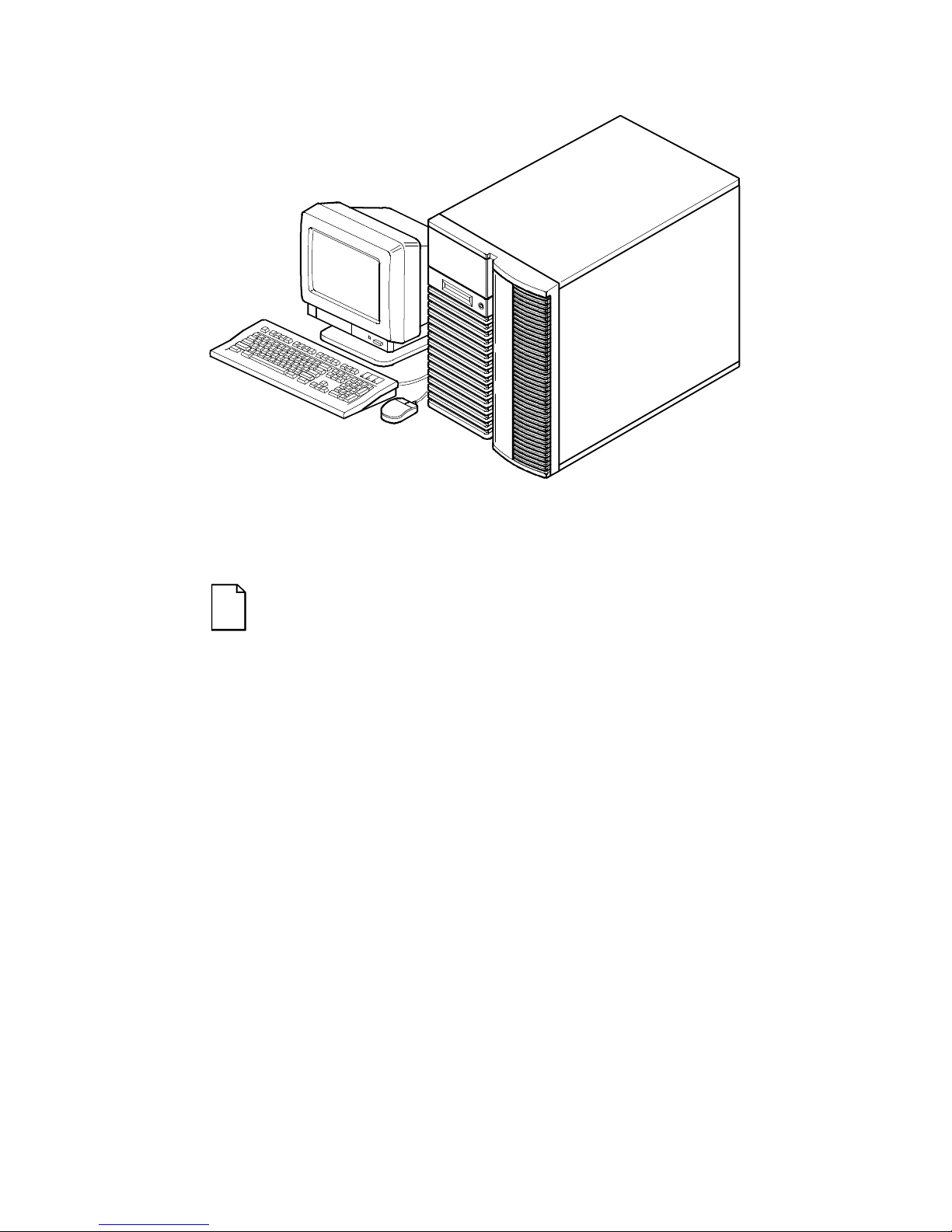
Typical Prioris ZX 6000MP Series................................................ xvi
1-1. Providing a Comfortable Working Environment ............................. 1-8
2-1. SCU Main Menu Options.............................................................. 2-7
3-1. Server Brake ................................................................................ 3-2
3-2. Unlocking and Removing the Side Panels..................................... 3-4
3-3. Installing Side Covers................................................................... 3-5
3-4. Server Front View......................................................................... 3-7
3-5. Server Left Side View................................................................... 3-9
3-6. Server Right Side View................................................................. 3-11
3-7. Server Rear View.......................................................................... 3-13
3-8. Main Logic Board Connectors....................................................... 3-15

Contents
viii
3-9. Main Logic Board Components..................................................... 3-17
3-10. CPU Module Components and Connectors................................... 3-19
3-11. Replacing the Server Battery/RTC................................................ 3-22
4-1. Prioris ZX 6000MP Series Server Component Information............ 4-3
5-1. CPU Slot Locations....................................................................... 5-3
5-2. Removing the Terminator Card..................................................... 5-5
5-3. Installing a CPU Module................................................................ 5-7
6-1. MLB SIMM Interleave and Bank 0 Locations................................. 6-4
6-2. Memory Module 1 and 2 SIMM Bank Locations ............................ 6-5
6-3. Installing a SIMM (MLB)................................................................ 6-7
6-4. Memory Module Removal............................................................. 6-9
6-5. Installing a SIMM (Memory Module).............................................. 6-11
7-1. Five Connector SCSI Cable.......................................................... 7-7
7-2. Storage Backplane ....................................................................... 7-8
7-3. Installing a Half-Height 5¼-Inch Device Into Top-Right Drive Bay.. 7-11
7-4. Installing a Full-Height 5¼-Inch Device Into Top-Right Drive Bay.. 7-13
7-5. Installing Expansion Brackets ....................................................... 7-15
7-6. Installing a Device Into the Hot-Swap Drive Bay............................ 7-17
7-7. External SCSI Bus Connections.................................................... 7-21
7-8. Connecting an External SCSI Storage Box to a SCSI Controller ... 7-23
8-1. Expansion Board Slot Locations.................................................... 8-2
8-2. EISA/PCI Scan Order................................................................... 8-7
8-3. Removing a Metal Filler Plate ....................................................... 8-13
8-4. Installing an ISA Expansion Board................................................ 8-14
8-5. Installing an EISA Expansion Board.............................................. 8-16
8-6. Installing a PCI Expansion Board.................................................. 8-18
9-1. Single Channel SCSI Configuration............................................... 9-5
9-2. Two Channel SCSI Configuration.................................................. 9-7
9-3. Three Channel SCSI Configuration............................................... 9-9
10-1. Front Panel Security Doors Lock................................................... 10-2
10-2. Left and Right Side Panel Lock..................................................... 10-3
A-1. Main Logic Board Switch Location................................................. A-8
A-2. CPU Module Switch Location ........................................................ A-12

ix
About This Guide
Introduction
This guide describes how to operate, upgrade, configure, and troubleshoot your Prioris ZX 6000MP (Multi-Processing) Series. This guide will
also help to familiarize you with all aspects of the server and provide a
reference tool for questions you might have in the future.
If you are initially setting up your server, refer to the
Server Installation
Guide
.
The
Server Installation Guide
identifies all the components that were
shipped from the factory as well as how to connect the mouse, keyboard,
monitor, and ac power.
The
Server Installation Guide
shows how to turn your server on for the first
time and access the ServerWORKS Quick Launch program. You must run
the ServerWORKS Quick Launch program to initially configure your
server, create utility and device driver diskettes, and install an operating
system.
Audience
This guide is written specifically for anyone responsible for operating,
configuring, and expanding the Prioris ZX 6000MP Series.

About This Guide
x
Support Information
A variety of support information is available to help you set up, configure,
and operate your Prioris ZX 6000MP Series. This information comes in the
form of README information, on-line help, electronic books, or as printed
material.
If you want to... Refer to the...
Set up your server
Server Installation Guide
to unpack, install
internal components, connect external
devices and power, and access the
ServerWORKS Quick Launch program.
Load the supplied
ServerWORKS software
ServerWORKS Quick Launch Reference
Guide
.
README information contained on the
ServerWORKS Quick Launch CD-ROM
disk.
Locate the major internal
components of your Prioris ZX
6000MP Series
Side Panel Labels
on your server’s side
panels.
Upgrade and configure your
server after installing optional
components (for example, a
CPU module, memory, mass
storage devices, SCSI or RAID
adapters, etc.)
Information supplied in this User’s Guide.
Supplied SCSI, RAID, and other options
documentation.
Run diagnostics
ServerWORKS Quick Launch Reference
Guide
and the Quick Launch program on
the supplied CD-ROM disk.
Supplied diagnostics documentation.

About This Guide
xi
Organization
This guide contains the following:
• Chapter 1:
Introduction
— This chapter provides general
information about your server. For example: features, server
software and support documentation, diagnostic software, server
utilities and technical support, and providing a comfortable working
environment.
• Chapter 2:
Server Utilities
— This chapter describes the server utilities
that are supplied on the ServerWORKS Quick Launch CD-ROM disk.
• Chapter 3:
Server Components
— This chapter provides general
information about your server’s components. For example:
procedures for removing the side panels, removing the server
components, and information about the System Configuration Utility
(SCU).
• Chapter 4:
Server Management
— This chapter describes how to
manage your server using a network manager, specifically Digital’s
ServerWORKS manager. It also provides a list and description of
error messages that might display and error codes that might
sound if a failure occurs.
• Chapter 5:
Upgrading Your Server’s CPU Module Configuration
—
This chapter describes how to upgrade your server with higherperformance CPU modules.
• Chapter 6:
Installing Additional Memory
— This chapter describes
how to install additional memory on the main logic board and
optional memory modules.
• Chapter 7:
Installing Optional Disk and Tape Drives
— This chapter
describes how to install optional disk and tape drives and an
external storage box.
• Chapter 8:
Installing Expansion Boards
— This chapter describes
how to install ISA, EISA, and PCI expansion boards.

About This Guide
xii
• Chapter 9:
Connecting SCSI and RAID Adapters
— This chapter
describes how to connect mass storage devices to supported SCSI
or RAID adapters.
• Chapter 10:
Server Security Features
— This chapter describes
the various security features that are available to prevent server or
data theft.
• Chapter 11:
Problem Solving and Troubleshooting
— This chapter
describes initial and advanced troubleshooting solutions.
• Appendix A:
Technical Specifications
— This appendix lists server
operating specifications. Main logic board and CPU module switch
information is also included.
• Appendix B:
Device Mapping
— This appendix provides a series of
tables listing mapping and address information related to server
memory and various main logic board devices (keyboard controller,
interrupt controller, Direct Memory Access (DMA) controller, etc.).
• Appendix C:
SCU Features
— This appendix lists the available SCU
resource and configuration options.
• Appendix D:
Caring For Your Server
— This appendix provides
suggestions for cleaning and moving your server.

About This Guide
xiii
Conventions
Convention
Example
Description
Reference Guide
Italics are typically used for titles, comments, and
references to other sections of this document or other
documents.
c:\windows>
SCU.BAT
Monospaced text indicates information that your server
or software displays. For example, a directory path or
error message.
Monospaced text can also indicate a command that you
need to enter to run an application or utility.
[Enter] Square brackets surrounding text represents a keyboard
key.
[Ctrl]+[Alt]+[Del] A plus sign indicates that the keys shown should be
pressed at the same time.

About This Guide
xiv
Abbreviations
Abbreviation Meaning
BIOS Basic input/output system
CPU Central processing unit
DIMM Dual in-line memory module
DMA Direct memory access
DRAM Dynamic random access memory
ECC Error correction code
ECP Extended capabilities port
EISA Extended industry standard architecture
EPP Enhanced parallel port
FRU Field replaceable unit
IDE Integrated drive electronics
h An h suffix to a numerical value denotes hexadecimal
numbers. For example, 0F8h equals 0F8 hexadecimal.
I/O Input/output
ISA Industry standard architecture
MS-DOS
Microsoft Disk Operating System
PCI Peripheral component interconnect
POST Power-on self test
RAID Redundant array of independent devices
RAM Random access memory
ROM Read only memory
continued
About This Guide
xv
Abbreviation Meaning
RTC Real-time clock
SBB Storage building block
SCSI Small computer system interface
SCU System Configuration Utility
SIMM Single in-line memory module
SMP Symmetrical multi-processor
VGA Video graphics array
Windows NT Microsoft Windows NT operating system software
ZIF Zero insertion force
Special Notices
Three kinds of special notices are used in this guide to emphasize specific
information.
WARNING: Indicates the presence of a hazard that
can cause personal injury if the hazard is not avoided.
CAUTION: Indicates the presence of a hazard that
might cause damage to hardware or that might corrupt
software.
NOTES: Used to provide additional information.
About This Guide
xvi
DEC00421
Typical Prioris ZX 6000MP Series
NOTE: Your monitor, keyboard, and mouse might look
different.

1-1
1
Introduction
The Prioris ZX 6000MP Series are high-performance, highly-scaleable
network and application servers featuring the latest in modular CPU and
storage technology.
The Prioris ZX 6000MP Series provides the following features:
Reliability/Availability
CPU Module
Single (1P) or Multiple (MP) Pentium Pro processor
mode. Each CPU operates using a 64-bit memory
interface and an internal L2 cache.
Error Correction Code
(ECC) Memory
Recovery from single-bit cache and memory errors.
Dual-Channel Storage
Backplane
Redundant disk subsystems using two SCSI
controllers or one dual-channel controller.
Power Supplies
The Prioris ZX 6000MP Series is shipped with two
power supplies for normal operation. In some
configurations, the second power supply can be used
for redundant operation.
Variable Fan Speed
Automatically adjusts fan speed according to ambient
temperature.
Internal Sensors
Monitors internal server temperatures, fan operation,
and power supply temperatures and voltages.

Introduction
1-2
Server Exp ans ion
Flexible Memory
Architecture
Provides 4-way interleaved data path with ECC
protection. Server memory can be upgraded from 64
MB to 2 GB using optional memory modules.
Four EISA Expansion
Slots, Seven PCI
Expansion Slots, and
one shared EISA/PCI
slot
Accommodates industry-standard expansion boards
such as network, Small Computer System Interface
(SCSI), Redundant Array of Integrated Disks (RAID),
and modems.
Integrated SVGA
Video Controller
Supports management and configuration applications
locally without use of an expansion slot.
Capacity for 10
internal SCSI Storage
Devices
Accommodates seven 3½-inch half-height drives in
Storage Building Blocks (SBBs), two 5¼-inch, halfheight drives (hard drives or tape drives), and one CDROM drive.
External I/O Ports
Two serial ports and one parallel port support external
options such as a printer, modem, or local terminal.
Wide-Ready SCSI
Storage Backplane
Allows for upgrades as new high-performance drives
become available.
Hot Swap Disk
Capability
Allows replacement of SBB disk drives while the server
is operating.

Introduction
1-3
Server Management
Server Diagnostics
Allows local and remote diagnosis of server
problems.
Hardware
Configuration
Allows local and remote server configuration.
Unique Asset
Management
Unique server identifier in non-volatile memory
provides easy asset management.
RAM-Based Error Log
Records startup error messages.
Firmware Upgrade
Utility
Upgrades firmware versions.
Operator Control
Panel (OCP)
Back-lit, 16-character display for diagnostic and error
messages.
Hard Drive Indicator
Lights
Provides immediate status information on SBB hard
drive activity or failure.
Server Security
Key Lock
Limits access to server components.
Interlock Sensor
Switches
Automatically turns off server power if either side
panel is removed when the server power is on.

Introduction
1-4
Server Software and Documentation
The following software and documentation are supplied with your server:
• ServerWORKS software kit contains ServerWORKS Quick
Launch and ServerWORKS Manager.
− ServerWORKS Quick Launch consists of a bootable CD-
ROM disk and reference guide. The Quick Launch program
steps you through the initial server setup and operating
system installation process.
Refer to the ServerWORKS Quick Launch Reference Guide and the
ReadMe.txt file, which is located on the Quick Launch CD-ROM.
− ServerWORKS Manager consists of the software and
documentation.
• Server documentation box contains this User’s Guide, an
Installation Guide, a Documentation Overview, Warranty
information, Options manuals, and Registration Card.
NOTE: You might have ordered additional options such as
hard disk drives, tape back-up systems, CD-ROMs, or
modems that have been factory installed in your server. The
documentation and any related diskettes for these options
have also been provided. Save this material for future
reference.

Introduction
1-5
Diagnostic Software
Diagnostic software is shipped with your server on the Quick Launch CDROM. This software contains an advanced set of diagnostic utilities that
can be used to identify and correct problems you might encounter when
installing, configuring, or using your server. There are two ways to access
the supplied diagnostic software:
1. During your server installation process, the diagnostic software will
be automatically copied to a subdirectory on the MS-DOS partition
(only if you selected the option to create an MS-DOS partition).
This allows you to run the diagnostic software anytime from the
MS-DOS partition you created.
2. Using the Install Software Conventional method in ServerWORKS
Quick Launch, you can create a bootable diagnostic software
diskette. This allows you to run the diagnostic software anytime
using the diskette you created.
For additional information, read any README files that are on the diagnostic
diskette you created.
NOTE: Digital strongly recommends that you copy the
diagnostics to a diskette and use this diskette to run the
diagnostics on your server.
Server Ut ilities a nd Technic al Support
Current server utilities and technical support information is available on
the Quick Launch CD-ROM disk and the Digital Bulletin Board Service
(BBS). For access to the Digital BBS in the USA, dial (508) 496-8800.
If you need additional information, access “Service Information” located in the
ServerWORKS Quick Launch program that is on your CD-ROM disk.

Introduction
1-6
Important Ergonomic Information
Under circumstances of poor posture or poor setup, certain recent
scientific articles suggest that injuries may occur. Other articles suggest
that there is no cause and effect. Because the safety of our users is a
great concern, it is important to take these precautions:
• Be comfortable in your work space.
• Change your posture frequently.
• Proceed according to the recommendations in the following table
and figure.
Adjus t So . . .
Chair Feet are flat on the floor.
Legs are vertical forming a right angle to the floor.
Your weight is off your thighs and they are horizontal. Keep the
back of your knees away from the seat so you do not compress
the area behind them, which could restrict the blood flow.
Your upper body is erect and your lower back is supported with
a backrest.
Keyboard or mouse Your wrists are straight and do not bend more than 15 degrees.
They may be supported when resting but not on sharp edges.
Type comfortably, with no more key pressure than needed to
feel the contact point.
Upper arms are straight down at your sides, elbows are close to
your sides and support your arm weight. Forearms are at a 70
degree to 90 degree angle.
If you use a mouse, rest your hand on the mouse so your wrist
is not on the work surface. Operate the mouse close to your
body’s centerline.
continued

Introduction
1-7
Adjus t So . . .
Head Avoid neck strain. Your head should incline downward, but no
more than 15 to 20 degrees.
Monitor No higher than the level of your eyes and at the correct
distance for your vision.
Avoid eye fatigue, which can be caused by glare, image
quality, uncomfortable furniture, eye height, and uncorrected
vision. If you cannot focus to read at different distances, you
may need special glasses. Relax your eyes periodically by
looking at distant objects.
Work breaks Take periodic work breaks. Morning, lunch, and afternoon
breaks during the 8-hour workday meet most
recommendations. Take advantage of work breaks to move
around and do other activities.
Lighting Avoid direct lighting or sunlight on the screen, which causes
glare and reflections. Place lighting behind or to the side of
your work area, and distribute the lighting evenly on your work
area.
Your server’s monitor screen has an antiglare treatment to
reduce glare. Adjust the brightness and contrast controls as
needed.
Noise Keep background noise at a minimum. Background noise
above 65 dBA is tiring. Sound-absorbing materials (curtains,
carpeting, and acoustic tile) can help reduce background
noise.
Temperature 20 to 23 degrees C (68 to 74 degrees F).
Humidity 30% to 70%.
Ventilation Provide adequate air ventilation to avoid fatigue and to
operate the equipment.
Space between set ups > 70 cm (28 in.) center to center, preferably
> 152 cm (60 in.).

Introduction
1-8
IMPORTANT: If you experience pain or discomfort
during use of the server, take a rest break and review the
instructions for proper ergonomic setup and use. If the
pain or discomfort continues after resuming use of the
server, discontinue use and report the condition to your
job supervisor or physician.
DEC00454
Figure 1-1. Providing a Comfortable Working Environment

2-1
2
Server Utilities
Introduction
This chapter describes the utilities supplied with your server. Server
utilities include:
• SCSI
Select
Utility This utility allows you to configure and view
settings of the installed Adaptec SCSI controllers and SCSI
devices.
• RAID Configuration Utility This utility is available for RAID-ready
servers only. This utility allows you to configure your RAID array.
• Flash Utility This utility allows you to update or restore your
server’s BIOS.
• EPP3SMC.EXE This device driver allows you to configure your
server’s parallel port as an enhanced parallel port (EPP).
• System Configuration Utility (SCU) This utility allows you to
configure your server when relocating, adding, or removing
EISA/ISA/PCI expansion boards and when changing your server’s
factory-defined settings.
 Loading...