

Prioris HX 6000 Series Service Maintenance Manual

PRIORIS HX 6000
Prioris HX 6000 Series Server
Service Maintenance Manual
Part Number: ER-B50WW-SM. A01
Digital Equipment Corporation

March 1997
The information in this document is subject to change without notice and should not
be construed as a commitment by Digital Equipment Corporation.
Digital Equipment Corporation assumes no responsibility for any errors that might
appear in this document.
The software, if any, described in this document is furnished under a license and may
be used or copied only in accordance with the terms of such license. No responsibility
is assumed for the use or reliability of software or equipment that is not supplied by
Digital Equipment Corporation or its affiliated companies.
Restricted Rights: Use, duplication, or disclosure by the U.S. Government is subject
to restrictions as set forth in subparagraph (c) (1) (ii) of the Rights in Technical Data
and Computer Software clause at DFARS 252.227-7013.
Prioris HX 6000 Series Server Service Maintenance Manual
Copyright Digital Equipment Corporation.
All Rights Reserved.
DEC, Prioris, ServerWORKS, and the Digital logo are trademarks of Digital
Equipment Corporation.
Intel and Pentium Pro are registered trademarks of Intel Corporation.
Micros o ft, Windows NT, and Windows 95 are registered trademarks of Microsoft
Corporation.
Novell and NetWare are U.S. registered trademarks of Novell Inc.
OS/2 and PS/2 are registered trademarks of International Business Machines
Corporation.
PhoenixBIOS is a trademark of Phoenix Technologies Ltd.
SCO UNIX is a trademark of The Santa Cruz Operation, Inc.
SCSI
Select
is a registered trademark of Adaptec Corporation.
SIMM is a registered trademark of Wang Laboratories.
All other trademarks and registered trademarks are the property of their respective
holders.

PRIORIS HX 6000
FCC ID: A 0 9 -B 5 XWW
The FCC wa nt s y ou to k now...
This equipment has been tested and found to comply with the limits for a Class B
digital device, pursuant to Part 15 of the FCC rules. These limits are designed to
provide reasonable protection against harmful interference in a residential installation.
Any changes or modifications made to this equipment may void the user's authority
to operate this equipment.
This equipment generates, uses, and can radiate radio frequency energy and, if not
installed and used in accordance with the instructions, may cause harmful
interference to radio communications. However, there is no guarantee that
interference will not occur in a particular installation. If this equipment does cause
harmful interference to radio or television reception, which can be determined by
turning the equipment off and on, the user is encouraged to try to correct the
interference by one or more of the following measures:
• Reorient or relocate the receiving antenna
• Increase the separation between the equipment and receiver
• Connect the equipment into an outlet on a circuit different from that to which
the receiver is connected
• Consult the dealer or an experienced radio/TV technician for help
All external cables connecting to this basic unit need to be shielded. For cables
connecting to option cards, see the option manual or installation instructions.
This digital apparatus does not exceed the Class B limits for radio noise emissions
set out in the radio interference regulations of the Canadian Department of
Communications.

This equipment is in the 2nd Class category (information equipment to be used in a
residential area or an adjacent area thereto) and conforms to the standards set by
the Voluntary Control Council For Interference by Data Processing Equipment and
Electronic Office Machines aimed at preventing radio interference in such residential
area.
When used near a radio or TV receiver, it may become the cause of radio
interference.
Read the instructions for correct handling.
This equipment meets or exceeds requirements for safety in the U.S. (UL 1950),
Canada (CSA C22.2 No. 950), and Europe (EN 60950/IEC 950) with Nordic
requirements.
This equipment meets or exceeds the ergonomic requirements of ZH1/618 and is
certified to bear the GS mark by TUV Rheinland of Germany.
This equipment has been tested for radio frequency emissions and has been verified
to meet VDE 0871 Class B.

i
PRIORIS HX 6000
Contents
1
Introduction
Reliability/Availability....................................................................................................... ...............1-1
Server Expansion........................................................................................................... ...............1-2
Server Management....................................................................................................... ...............1-3
Serve r S e c u ri ty............................................................................................................... ...............1-3
Server Software and Documentation ............................................................................. 1-4
Diagnostic Software........................................................................................................ 1-5
Server Utilities and Technical Support............................................................................ 1-5
Important Ergonomic Information................................................................................... 1-6
2
Server S oftware and Utilities
Introduction..................................................................................................................... 2-1
SCSISelect Utility............................................................................................................ 2-2
RAID Configuration Utility............................................................................................... 2-2
PHLASH.EXE................................................................................................................. 2-3
Using EPP3SMC.EXE.................................................................................................... 2-3
System Configuration Utility (SCU)................................................................................. 2-4
When to Run the SCU................................................................................................ 2-4
Configuring Expansion Boards ................................................................................... 2-5
Startin g th e SCU......................................................................................................... 2-6
Usin g th e SCU............................................................................................................ 2-8
SCU Keyboard Function Keys.................................................................................... 2-9
Configure C o mp u te r................................................................................................... 2-10
Setting the Date and Time.......................................................................................... 2-10
Mainta in Syste m Config u ra tion Diskette..................................................................... 2-11
ServerWORKS Quick Launch........................................................................................ 2-12
Diagnostics..................................................................................................................... 2-12

Contents
ii
3
Server Com ponents
Introduction..................................................................................................................... 3-1
Disconnecting External Devices and Power................................................................... 3-2
Removing and Installing the Side Panels ....................................................................... 3-3
Serve r F ro n t V iew........................................................................................................... 3-6
Serve r L e ft S ide Vi e w..................................................................................................... 3-8
Serve r R ight Si d e View................................................................................................... 3-10
Serve r R e a r View........................................................................................................... 3-12
Main Logic Board Connectors........................................................................................ 3-14
Main Logic Board Components...................................................................................... 3-16
CPU Module Components and Connectors................................................................... 3-18
Ethernet Daughter Card Components and Connectors ................................................. 3-20
Tools Needed................................................................................................................. 3-22
Static E lectric i ty.............................................................................................................. 3-22
Replacin g th e S e rv e r B a tte ry /R e a l Time Clock (R T C).................................................... 3-23
4
Server Managem ent
Introduction..................................................................................................................... 4-1
Managing Your Server ................................................................................................... 4-1
Obtaining Information about Your Server....................................................................... 4-2
Obtain ing Informa tion Us i n g th e SCU......................................................................... 4-4
Obtaining Information Using Server Management Software ...................................... 4-4
Disp layin g S e rv e r S ta tu s Using th e H a rd ware................................................................ 4-6
Serve r S ta tu s.............................................................................................................. 4-7
POST OCP Messages ................................................................................................... 4-9
POST/Boot Codes...................................................................................................... 4-9
OCP Messages.............................................................................................................. 4-11
OCP Status and Error Messages ............................................................................... 4-12
Server CPU Voltage and Temperature Ranges............................................................. 4-14
CPU Voltage Range ................................................................................................... 4-14
VRM Voltage Range................................................................................................... 4-14

Contents
iii
PRIORIS HX 6000
5
CPU Module U pgr ade Confi gur ations
Introduction..................................................................................................................... 5-1
Configurati o n Gu ideli n e s................................................................................................ 5-1
Server CPU Module Configurations ............................................................................... 5-2
CPU Module Upgrade Configurations............................................................................ 5-2
Upgrading to a New CPU Module Configuration............................................................ 5-4
6
Installing Additional Mem or y
Introduction..................................................................................................................... 6-1
Server SIMMs Requirements......................................................................................... 6-2
Memory C o n fi g u ra tion Gui d e lines.................................................................................. 6-2
Upgra d ing Memory......................................................................................................... 6-3
Instal l ing SIMMs............................................................................................................. 6-3
Memory Troubleshooting................................................................................................ 6-7
7
Installing Disk and Tape Dr ives
Introduction..................................................................................................................... 7-1
Tape Drive Configuration Guidelines.............................................................................. 7-1
SBB Configuration Guidelines........................................................................................ 7-2
CD-R OM Drive C o n figurati o n Gu idelines....................................................................... 7-2
SCS I C o n figurati o n Gu idelines....................................................................................... 7-2
SCSI ID and Termination............................................................................................ 7-2
Setting IDs and Termination....................................................................................... 7-3
Boot D e v ice ................................................................................................................ 7-4
External Channel ........................................................................................................ 7-4
Storage Backplane ..................................................................................................... 7-5
Drive ID....................................................................................................................... 7-5
Cables......................................................................................................................... 7-6
Storage Backplane......................................................................................................... 7-7
Installing Optional Drives................................................................................................ 7-9
Instal l ing a H a lf-Hei g h t 5 ¼-In ch Devic e i n to th e T o p - R ight Drive Ba y........................ 7-10
Instal l ing a F u l l-Hei g h t 5 ¼-In c h D e v ice in to th e T o p -R ight Drive Ba y......................... 7-12
Expansion Brackets ................................................................................................ 7-14
Hot-Swap Drive Ba y................................................................................................... 7-16
SBB LED Status Indicators..................................................................................... 7-18

Contents
iv
Extern a l S to r a g e............................................................................................................. 7-20
Connecting an External SCSI Bus to the Storage Backplane..................................... 7-20
Connecting an External Device to a SCSI Controller.................................................. 7-22
8
Installing Expansion B oards
Introduction..................................................................................................................... 8-1
ISA/EISA Expansion Board Configuration Guidelines.................................................... 8-1
PCI Expansion Board Configuration Guidelines............................................................. 8-3
Configuring Your EISA/PCI Expansion Boards Using the SCU...................................... 8-3
Boot D e v ices.................................................................................................................. 8-4
Server Boot Sequence................................................................................................ 8-4
Server Scan Sequence............................................................................................... 8-5
Scan Order Depending on SCU Boot Sequence Preference..................................... 8-7
Examp l e s o f B o o t Devic e A s signmen t....................................................................... 8-7
Examp l e s o f E ISA/PC I S c a n Ord e r........................................................................ 8-7
Identifying PCI Devices in the SCU............................................................................. 8-10
Advanced Menu in the SCU ....................................................................................... 8-12
Locki n g o f Resou rce s............................................................................................. 8-12
View Additional System Information........................................................................ 8-12
Set Verification Mode Menu.................................................................................... 8-13
Mainta in SCI F ile Men u........................................................................................... 8-13
Installing Expansion Boards ........................................................................................... 8-13
Adding ISA Expansion Boards.................................................................................... 8-14
Installing ISA Expansion Boards................................................................................. 8-14
Installing EISA Expansion Boards............................................................................... 8-17
Adding EISA Expansion Boards ................................................................................. 8-18
Installing PCI Expansion Boards................................................................................. 8-19
Adding PCI Expansion Boards.................................................................................... 8-21
Relocating Expansion Boards..................................................................................... 8-22
9
Connecting SCS I and R AID Adapter s
Introduction..................................................................................................................... 9-1
SCS I C o n figurati o n Gu idelines....................................................................................... 9-1
RAID C o n figurati o n Gu idelines....................................................................................... 9-2
SCS I C o n tro ller C a b l e Config u ra tions............................................................................ 9-3
Single Backplane SCSI Configuration......................................................................... 9-4
Split Backplane Using Onboard SCSI Controllers Configuration ................................ 9-6
Split Backplane Using Two-Channel RAID Controller Configuration .............................. 9-8

Contents
v
PRIORIS HX 6000
10
Server S ecur ity Featur es
Introduction..................................................................................................................... 10-1
Left and Right Door Security Lock.................................................................................. 10-2
Left and Right Side Panel Lock ...................................................................................... 10-3
Supervisor Password...................................................................................................... 10-4
If You F o rg e t Y o u r Passw o rd......................................................................................... 10 -5
Additional Security Features........................................................................................... 10-6
11
Troubleshooting
Introduction..................................................................................................................... 11-1
Initial Troubleshooting..................................................................................................... 11-2
Running the Diagnostics................................................................................................. 11-3
Diagnostics Utility Keys............................................................................................... 11-4
Server Troubleshooting .................................................................................................. 11-5
Disk Drive Troubleshooting............................................................................................. 11-9
SBB Troubleshooting...................................................................................................... 11-12
Tape Drive Troubleshooting ........................................................................................... 11-12
Monitor Troubleshooting................................................................................................. 11-13
CD-ROM Troubleshooting.............................................................................................. 11-14
Diskette Drive Troubleshooting....................................................................................... 11-15
RAID Troubleshooting.................................................................................................... 11-16
12
Service Pr ocedur es
Introduction..................................................................................................................... 12-1
Recommended Tools..................................................................................................... 12-1
Other Materials Needed.............................................................................................. 12-1
Special Tools Required............................................................................................... 12-2
Remedial Diagnostic Test Software............................................................................ 12-2
Virus S o ftware Info rma ti o n......................................................................................... 12-2
BIOS Ve rs ion Info rma ti o n........................................................................................... 12-2
Restoring the Module Serial Number ............................................................................. 12-2
Removing and Replacing Components.......................................................................... 12-3
Removing and Replacing the Power Supply.................................................................. 12-4
Removing and Replacing the Diskette Drive.................................................................. 12-6
Removing and Replacing the CD-ROM Drive................................................................ 12-8
Removing and Replacing a Cooling Fan........................................................................ 12-10

Contents
vi
Removing and Replacing the Secondary Cooling Fan 2............................................... 12-12
Removing and Replacing Cooling Fan 5........................................................................ 12-14
Removing and Replacing the Speaker........................................................................... 12-16
Removing and Replacing the Main Logic Board............................................................. 12-18
Removing and Replacing the Storage Backplane.......................................................... 12-20
Removing and Replacing a Caster................................................................................. 12-22
13
Field Service IPB
Introduction..................................................................................................................... 13-1
Serve r F ro n t V iew........................................................................................................... 13-2
Serve r L e ft-S ide Vi e w..................................................................................................... 13-4
Serve r R ight-Si d e /Rear View.......................................................................................... 13-6
Miscellaneous................................................................................................................. 13-8
Labels and Nameplates.................................................................................................. 13-8
14
Field Service Notes
............................................................................................... 14-1
15
Product Refer ence and S uppor t
Introduction..................................................................................................................... 15-1
A
Technical Specifications
Introduction..................................................................................................................... A-1
Serve r S p e c i ficatio n s...................................................................................................... A-1
Performa n c e S p e c i ficatio n s........................................................................................ A-2
Serve r D imensi o n s..................................................................................................... A-2
Envi ro n me n ta l Spec i ficatio n s...................................................................................... A-3
EISA Expansion Slots..................................................................................................... A-3
PCI Local Bus Expansion Slots...................................................................................... A-3
Power Supply Input Power Requirements...................................................................... A-4
Power Supply Output Specifications............................................................................... A-4
Power Cord Requirements............................................................................................. A-5
Envi ro n me n ta l Featu re s................................................................................................. A-6
Main Logic Board Switch and Jumper Settings.............................................................. A-7
CPU Module Switch and Jumper Settings...................................................................... A-10

Contents
vii
PRIORIS HX 6000
B
Device Mapping
Introduction..................................................................................................................... B-1
CPU Me mo ry A d d re s s Ma p........................................................................................ B-2
I/O Addre s s Ma p ......................................................................................................... B-3
Serve r In te rru p t L e ve ls ............................................................................................... B-4
PCI C o n fi g u r a ti o n S p a c e A d d r e ss Ma p...................................................................... B-4
C
SCU Features
Introduction..................................................................................................................... C-1
System - Priori s HX Series Se rv e r.............................................................................. C-2
System Management Group ...................................................................................... C-3
Disk e tte Drive Gro u p.................................................................................................. C-4
Boot Op ti o n s Gro u p.................................................................................................... C-5
Integrated Peripherals Group ..................................................................................... C-5
Keyboard Features Group.......................................................................................... C-8
Shadow Options Group .............................................................................................. C-9
Secu ri ty Op ti o n s Gro u p.............................................................................................. C-10
Cach e Op ti o n s Gro u p................................................................................................. C-11
Adva n ce d Control Gro u p............................................................................................ C-11
EISA o r P C I Devic e s Gro u p ........................................................................................ C-12
D
Caring for Your S er ver
Introduction..................................................................................................................... D-1
Cleaning the Server........................................................................................................ D-2
Cleaning the Screen....................................................................................................... D-2
Cleaning the Mouse........................................................................................................ D-2
Movin g th e S e rv e r.......................................................................................................... D-3
Packing the S e rv e r..................................................................................................... D-3
Instal l ing the S e rv e r a t a N e w Location....................................................................... D - 4

ix
PRIORIS HX 6000
0
Preface
P
This
Service Maintenance Manual
is a troubleshooting guide that can be used for
reference when servicing Prioris HX 6000 Series servers.
Digital reserves the right to make changes to this
Service Maintenance Manual
without notice. Accordingly, the illustrations and procedures in this document might
not apply to all Prioris HX 6000 Series servers to be serviced since many of the
diagnostic tests are designed to test more than one product.
CAUTION:
Digital recommends that only A+ certified
engineers attempt to repair this equipment. All
troubleshooting and repair procedur es ar e det ailed to suppor t
subassembly/module level exchange. Because of the
complexity of the individual boards and subassemblies, no
one should atttempt to make repairs at the component level or
make modifications to any printed circuit boar d. I m pr oper
repairs can create a safet y hazar d. Any indications of
component replacement or cir cuit boar d modifications might
void any warranty or exchange allowances.

Preface
x
Organization
This guide contains the following:
•
Chapter 1:
Introduction
— This chapter provides information about your
server such as: features, server software and documentation, diagnostic
software, server utilities and technical support, and ergonomic information.
•
Chapter 2:
Server Sof tware and Utilities
— This chapter describes the
server sof tware and utilities that are supplied wit h y our s er v er .
•
Chapter 3:
Server Component s
— This chapt er pr ov ides information about
the server’s c om ponents and associat ed pr oc edur es s uc h as r em ov ing the
side panels.
•
Chapter 4:
Server Management
— This chapter describes how to manage
your server using a network manager, specifically Digital’s ServerWORKS
Manager. It also provides a list and description of error messages that might
display and error codes that might sound if a failure occurs.
•
Chapter 5:
CPU Module Upgrade Configurations
—
This chapter describes
how to upgrade your server with higher-performance CPU modules.
•
Chapter 6:
Installing Additional Memory
— This chapter describes how to
install additional memory on the CPU module.
•
Chapter 7:
Installing Disk and Tape Drives
— This chapter describes how to
install optional disk drives, tape drives, and an external storage box.
•
Chapter 8:
Installing Expansion Boards
— This chapter describes how to
install ISA, EISA, and PCI expansion boards.
•
Chapter 9:
Connecting SCSI and RAID Adapters
— This chapter describes
how to connect mass storage devices to the onboard SCSI controller or to
supported RAID adapters.
•
Chapter 10:
Server Security Features
— This chapter describes the various
security features that are available to prevent server or data theft.

Preface
xi
PRIORIS HX 6000
•
Chapter 11:
Troubleshooting
— This chapter describes initial and advanced
troubleshooting s olutions.
•
Chapter 12:
Field Service Replac em ent
— This chapter describes field
service replacem ent procedures. For example, the main logic board, power
supplies, fans , etc.
•
Chapter 13:
Field Service Illustrat ed P ar ts Breakdown
— This chapt er lis ts
orderable part number s for Field Replaceable Unit s ( FRUs).
•
Chapter 14:
Field Service Notes
— This chapt er enables field service
personnel to recor d per tinent servic e information.
•
Chapter 15:
Product Ref er enc e and S uppor t
— This chapt er lis ts product
reference and suppor t informat ion.
•
Appendix A:
Technical Specifications
— This appendix lists server operating
specifications. Also included is switch information on the main logic board
and CPU module.
•
Appendix B:
Device Mapping
— This appendix provides a series of tables
listing mapping and address information related to server memory and
various main logic board devices (keyboard controller, interrupt controller,
Direct Memory Access (DMA) controller, etc.).
•
Appendix C:
SCU Features
— This appendix lists the available SCU
resource and conf igur ation options.
•
Appendix D:
Caring For Your S er v er
— This appendix prov ides s ugges tions
for cleaning and moving y our s er v er .

Preface
xii
Conventions
Convention
Example
Description
Installation Guide
Italics are typically used for titles, com m ent s, and r ef er ences
to other sections of t his document or other documents.
c:\windows>
SCU.BAT
Monospaced text indicates informat ion that your server or
software displays. For example, a direct or y pat h or er r or
message.
Monospaced text can also indicate a command that you need
to ent e r to r un a n ap p lic a tion or u tility.
[Enter] Square brackets surrounding text r epr esent s a keyboar d key.
[Ctrl]+[Alt]+[ Del] A plus sign indicates that the keys shown should be pressed
at the same time.
Abbreviations
Abbreviation Meaning
BIOS Basic input/output system
CPU Central processing unit
DIMM Dual in-line memory module
DMA Direct memory access
DRAM Dynamic random access memory
ECC Error correction code
ECP Extended capabilities por t
EISA Extended industry standard architectur e
EPP Enhanced parallel port
FRU Field replaceable unit
IDE Integrated dr ive electr onics
continued

Preface
xiii
PRIORIS HX 6000
Abbreviation Meaning
h An h suffix to a numerical value denotes hexadecimal
numbers. For exam ple, 0F8h equals 0F8 hexadecimal.
I/O Input/output
ISA I ndust r y st andar d ar chit ect ur e
MS-DOS
Microsoft Disk Operating System
PCI Peripheral component interconnect
POST Power-on self test
RAID Redundant array of independent devices
RAM Random access memor y
ROM Read only memor y
RTC Real-t ime clock
SBB Storage building block
SCSI Sm all computer syst em int erface
SCU Syst e m Config uration Utility
SIMM Single in-line memory m odule
SMP Symmetrical multi-pr ocessor
VGA Video graphics array
Windows NT Microsof t Windows NT operating system sof t ware
ZIF Zero insertion force
Preface
xiv
Special Notices
Three kinds of special notices are used in this System Reference to emphasize
specific information.
WARNING:
Indicates the presence of a hazar d t hat can
cause personal injury if the hazard is not avoided.
CAUTION:
Indicates the presence of a hazard that might
cause damage to hardware or t hat might corrupt sof tware.
NOTES:
Used to provide additional information.
Preface
xv
PRIORIS HX 6000
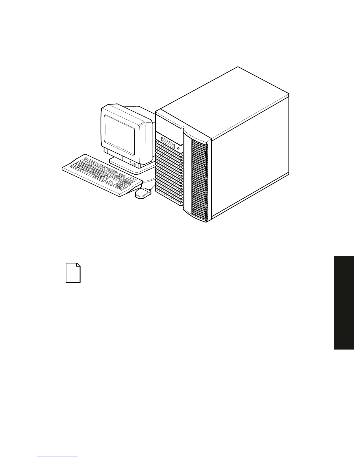
DEC00421
Typical Prioris HX 6000 Series Server
NOTE:
Your monitor, keyboar d, and m ouse m ight look diff er ent .

1-1
PRIORIS HX 6000
1
Introduction
1
The Prioris HX 6000 Series server is a high-performance, highly-scaleable network
and application server featuring the latest in modular CPU and storage technology.
The Prioris HX 6000 Series server provides the following features:
Reliability/Availability
CPU Module
Single (1P) or Dual (2P) Pentium Pro processor mode.
Each CPU operates using a 64-bit memory interface and
an internal L2 cache.
Error Correction Code
(ECC) Memory
Recovery from single-bit cache and memory errors.
Dual-Channel Storage
Backplane
Redundant disk subsystems using integrated SCSI
controllers or expansion storage controllers.
Power Supply
The Prioris HX 6000 Series server is shipped with one
power supply for normal operation.
Variable Fan Speed
Automatically adjusts fan speed according to ambient
temperature.
Internal Sensors
Monitors internal server temperatures, fan operation, and
power supply temperatures and voltages.

Introduction
1-2
Server Exp ans ion
Flexible Memory
Architecture
ECC memory support. Server memory can be upgraded
from 32 MB to 512 MB using the installed CPU module.
Five EISA Expansion
Slots and Six PCI
Expansion Slots
Accommodates industry-standard expansion boards such
as network, Small Computer System Interface (SCSI),
Redundant Array of Integrated Disks (RAID), and
modems.
Integrated SVGA Video
Controller
Supports management and configuration applications
locally (on the main logic board) without use of an
expansion slot.
Two Integrated SCSI
controllers
Support for both narrow and fast wide external and internal
SCSI devices.
Capacity for 11 internal
SCSI Storage Devices
Accommodates one CD-ROM drive (standard), a 3 1/2
inch floppy (standard), seven 3½-inch half-height drives in
Storage Building Blocks (SBBs), and two narrow (50-pin)
half-height, 5¼-inch devices; or one full-height, 5¼-inch
device (CD-ROMs or tape drives).
External I/O Ports
Two serial ports and one parallel port to support external
options such as a printer, modem, or local terminal.
Wide-Ready SCSI
Storage Backplane
Supports high-performance drives.
Hot Swap Disk Capability
Allows replacement of SBB disk drives while the server is
operating.
External network ports
One 10/100Base-T (10/100 Mb/s) port, one 10Base-2 (10
Mb/s) port to support external network connections, and
one 10Base-5 (AUI) port.
Integrated Network
Controller
Provided by a Digital Ethernet Controller on the main logic
board.

Introduction
1-3
PRIORIS HX 6000
Server Management
Server Diagnostics
Allows local and remote diagnosis of server problems.
Hardware Configuration
Allows local and remote server configuration.
Unique Asset
Management
Unique server identifier in non-volatile memory provides
easy asset management.
Firmware Upgrade Utility
Upgrades firmware versions.
Operator Control Panel
(OCP)
Back-lit, 16-character display for diagnostic and error
messages.
Hard Drive Indicator
Lights
Provides immediate status information on SBB hard drive
activity or failure.
Server Security
Key Lock
Limits access to server components.
Interlock Sensor
Switches
Automatically turns off server power if either side panel is
removed when the server power is on.

Introduction
1-4
Server Software and Documentation
The following software and documentation are supplied with your server:
•
ServerWORKS Manageability Suite
contains ServerWORKS Quick
Launch, ServerWORKS Manager, and licenses.
−
ServerWORKS Quick Launch consists of a bootable CD-ROM disk
and reference guide. The Quick Launch program steps you through
the initial server setup and operating system installation process.
Refer to the ServerWORKS Quick Launch Reference Guide and the ReadMe.txt file,
which is located on the Quick Launch CD-ROM.
−
ServerWORKS Manager consists of two CD-ROMs, several floppy
diskettes, User Guide, and supporting documentation.
•
Server documentation box
contains this System Reference, an
Installation Guide, a Documentation Overview, Warranty information,
Options manuals, and Registration Card.
NOTE:
You might have ordered additional options such as hard
disk drives, tape back-up systems, CD-ROM s, or m odem s that
have been factory installed in your server. The docum entation
and any related diskettes for t hese opt ions have also been
provided. Save this material for f ut ur e r ef er ence.

Introduction
1-5
PRIORIS HX 6000
Diagnostic Software
Diagnostic software is shipped with your server on the Quick Launch CD-ROM. This
software contains an advanced set of diagnostic utilities that can be used to identify
and correct problems you might encounter when installing, configuring, or using your
server. There are two ways to access the supplied diagnostic software:
1. During your server installation process, the diagnostic software will be
automatically copied to a subdirectory on the MS-DOS partition (only if you
selected the option to create an MS-DOS partition). This allows you to run
the diagnostic software anytime from the MS-DOS partition you created.
2. Using the Installations & Utilities button and then selecting the Utilities page
from the ServerWORKS Quick Launch CD-ROM, you can create a
bootable diagnostic software diskette. This allows you to run the diagnostic
software anytime using the diskette you created.
For additional information, read any README files that are on the diagnostic diskette you
created.
NOTE:
Digital strongly recommends that you copy t he
diagnostics to a diskette and use this diskette to r un t he
diagnostics on your server.
Server Ut ilities and Technic al Support
Current server utilities and technical support information is available on the Quick
Launch CD-ROM disk and the Digital Bulletin Board Service (BBS). For access to
the Digital BBS in the USA, dial (508) 496-8800.
If you need additional information, access “Service Information” located in the
ServerWORKS Quick Launch program that is on your CD-ROM disk.

Introduction
1-6
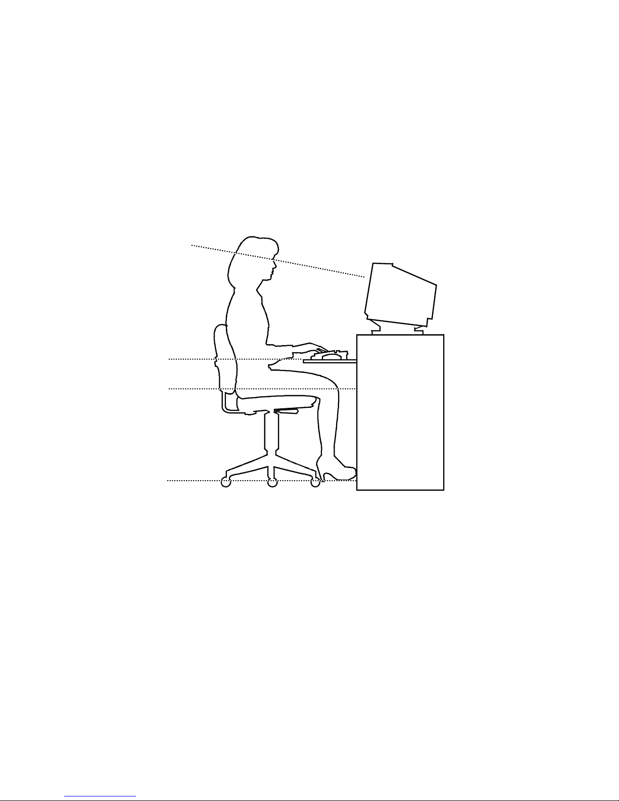
Important Ergonomic Information
After the server is installed, it is important to apply the following ergonomic
information.
•
Be comfortable in your work space.
•
Change your posture frequently.
•
Proceed according to the recommendations in the following table and figure.
Adjust So . . .
Chair Feet are flat on the f loor .
Legs are vertical form ing a right angle to t he floor.
Your weight is off your thighs and they ar e horizontal. Keep the
back of your knees away from t he seat so you do not com pr ess
the area behind them, which could rest r ict the blood flow.
Your upper body is erect and your lower back is supported with
a backrest.
Keyboard or mouse Your wr ist s ar e st r aight and do not bend m or e than 15 degrees.
They may be supported when resting but not on shar p edges.
Type comfortably, with no mor e key pr essur e t han needed t o
feel the contact point.
Upper arms are str aight down at your sides, elbows are close to
your sides and support your arm weight. For ear m s ar e at a 70
degree to 90 degree angle.
If you use a mouse, r est your hand on t he m ouse so your wrist
is not on the work surface. Operate the mouse close t o your
body’s centerline.
continued

Introduction
1-7
PRIORIS HX 6000
Adjust So . . .
Head Avoid neck strain. Your head should incline downward, but no
more than 15 to 20 degr ees.
Monitor No higher than the level of your eyes and at t he cor r ect dist ance
for your vision.
Avoid eye fatigue, which can be caused by glare, image quality,
uncomfortable fur nitur e, eye height, and uncorrected vision. If
you cannot focus to read at diff er ent dist ances, you m ay need
special glasses. Relax your eyes periodically by looking at
distant objects.
Work breaks Take periodic work breaks. Morning, lunch, and aft er noon
breaks during the 8-hour workday m eet m ost r ecom m endat ions.
Take advantage of work breaks t o m ove ar ound and do ot her
activities.
Lighting Avoid direct lighting or sunlight on the screen, which causes
glare and reflections. Place lighting behind or to the side of your
work area, and distribute t he lighting evenly on your work ar ea.
Your server’s monitor scr een has an antiglare treatment to
reduce glare. Adjust the brightness and cont r ast cont r ols as
needed.
Noise Keep background noise at a minimum. Background noise above
65 dBA is tiring. Sound-absorbing materials (cur t ains, car pet ing,
and acoustic tile) can help reduce background noise.
Temperature 20 to 23 degrees C (68 to 74 degrees F) .
Humidity 30% to 70%.
Ventilation Provide adequate air ventilation to avoid fatigue and to operate
the equipment.
Space between set ups > 70 cm (28 in.) center t o center, pref er ably
> 152 cm (60 in.).
Introduction
1-8
IMPORTANT:
If you experience pain or discomfor t dur ing
use of the server, t ake a r est br eak and r eview the instr uct ions
for proper er gonom ic set up and use. I f the pain or discomfort
continues after resum ing use of t he ser ver , discont inue use
and report the condition to your job supervisor or physician.
DEC00454
Figure 1- 1 . Pr ov iding a C om for t a ble Wor k ing Env ir onm e nt

2-1
PRIORIS HX 6000
2
Server Software and Utilities
2
Introduction
This chapter describes the utilities supplied with your server. Server utilities include:
•
SCSI
Select
Utility This utility allows you to configure and view settings of
the installed Adaptec SCSI controllers and SCSI devices.
•
RAID Configuration Utility
This utility is available for RAID-ready servers
only. This utility allows you to configure your RAID array.
•
Flash Utility
This utility allows you to update or restore your server’s
BIOS.
•
EPP3SMC.EXE
This device driver allows you to configure your server’s
parallel port as an enhanced parallel port (EPP).
•
System Configuration Utility (SCU)
This utility allows you to configure
your server when relocating, adding, or removing EISA/ISA/PCI expansion
boards and when changing your server’s factory-defined settings.
•
ServerWORKS Quick Launch This software is used to install a network
operating system onto the server. The CD-ROM also contains various
drivers and on-line documentation.
•
Diagnostics This utility is used to verify server operation.

Server Software and Utilities
2-2
SCSI
Select
Utility
Your Prioris server comes with two onboard Adaptec 7880 SCSI controllers and a
SCSI
Select
configuration utility. This utility allows you to change host controller
settings without opening your server.
Use SCSI
Select
to:
•
Check factory default settings for each device on the SCSI bus.
•
Change SCSI device settings that might conflict with other SCSI devices.
•
Perform low-level formatting on new SCSI disk drives.
•
You must let the Adaptec controller spin up the drive before pressing [Ctrl] +
[A] so you can perform low-level formatting.
To start th e S C SI
Select
configuration utility:
Press [Ctrl] + [A] when the Adaptec BIOS banner appears during the boot process
and before the end of the device information display.
RAID Conf iguration U tility
RAID-ready Prioris HX 6000 Series servers include a Mylex RAID host adapter and
RAID configuration utility. The RAID configuration utility appears when you boot your
server with the ServerWORKS Quick Launch CD-ROM disk. Use this utility to
configure your RAID array.
Refer to the Mylex User’s Manuals for more information. These manuals are provided as
either hard-copy manuals or are located on the Quick Launch CD-ROM as on-line files under
the “Documentation” button.

Server Software and Utilities
2-3
PRIORIS HX 6000
PHLASH.EXE
All servers have BIOS software in a flash (ROM) chip. This BIOS initializes hardware
and boots the operating system when the server is turned on. The BIOS also
provides access to other services such as keyboard and disk drives.
You can upgrade your server's BIOS to future releases by executing the flash utility
located in the BIOS update kit.
Only use the flash utility to upgrade your server’s BIOS if you are instructed to do so
by an authorized Digital support representative. The flash utility and BIOS updates
are available on Digital’s BBS at (508) 496-8800.
Using EPP3SMC.EXE
EPP3SMC.EXE is a device dri ver that can be acce ssed from the Se rverWORKS
Quick Launch CD-ROM disk. This device driver can be used to configure your
parallel port as an enhanced parallel port (EPP). Before loading this device driver,
check the documentation for the device you want to connect to the parallel port and
make sure it supports EPP mode. If it does not, you do not need to load this device
driver. If the device does support EPP mode, you should:
1. Locate the EPP3SMC.EXE file on the MS-DOS partition you created during
the Quick Launch installation process.
Note the path where your driver is located:
C:\EPP\EPP3SMC.EXE
2. Edit yo ur CON FIG.SYS file to enter the path for EPP3SMC.EXE.
Refer to your MS-DOS documentation for information on editing your
CONFIG.SYS file. For example a line in your CONFIG.SYS might be:
device=C:\epp3smc.exe
3. Save the new version of your CONFIG.SYS file.

Server Software and Utilities
2-4
4. Press [Ctrl] + [Alt] + [Del] and reboot your server.
5. Run the SCU and choose the Parallel Port Group.
6. Choose either EPP 1.7 or EPP 1.9 mode.
Selection is based on which EPP your printer supports. If you do not know
which EPP your printer supports, use the default setting.
7. Exit the SCU to save the new setting.
Your parallel port is now configured as an EPP port.
System Configuration Utility (SCU)
Your server was pre-configured at the factory using the System Configuration Utility
(SCU). This means that your server’s hardware (CPU, memory, cache, mass
storage devices, expansion boards, etc.) has been identified and configured for
optimum performance. If you need to make changes to this configuration, Digital
recommends that you use the SCU along with the information provided in this
section.
Refer to “Starting the SCU” described later in this chapter.
Refer to Appendix C, “SCU Features,” for more details about the SCU.
Refer to the ServerWORKS Quick Launch Reference Guide and the ReadMe.txt file,
which is located on the Quick Launch CD-ROM, for additional information.
When to Run the SCU
Always run the SCU each time you add, remove, or relocate ISA, PCI and/or EISA
expansion boards to reconfigure server resources (IRQs, I/O address, memory
address, etc.). You should also run the SCU if the main logic board changed or after
adding memory to the installed CPU module.
If the main logic board changes or a CPU module is added, run the SCU (select the
option “Configure Computer”) to update the serial numbers of the components. For
more information on how to change the serial numbers, refer to Chapter 4, “Obtaining
Information About Your Server.”
Typically, your server displays a message such as
Run SCU
Utility.....Press F1 to Continue
. Select how you want to access and run
the SCU by following the instructions displayed on the SCU screens.
 Loading...