

Prior PureFocus850 User Manual
More to PRIOR than meets the eye
Version issue No. - 1.7
For more information visit www.prior.com
PureFocus850
User manual

Version issue No. - 1.7
Thank you for purchasing this product from Prior Scientic – we’re condent it will be a
reliable and useful addition to your microscopy system. Please take the time to read and
understand this manual before using this product – it contains not only important operating
instructions but also vital safety information. This product must be used only as specied in
this manual. If you wish to use it dierently, contact Prior Scientic beforehand.
Please do not hesitated to contact us with any comments or
questions regarding this product.
Visit Prior Scientic online at www.prior.com

More to PRIOR than meets the eye
For more information visit www.prior.com
1
Contents
Section 1
Safety Information 2
Section 2
Product description 3
Section 3
Unpacking the system 4
Section 4
Introduction
4.1 Working principle 6
4.2 Sample types 8
4.3 Types of microscope system 9
Section 5
Installation
5.1 Installing the head 10
5.2 Initalizing the head 11
5.3 Controller Motor Connections 14
5.4 Setting up for stepper focus control 15
5.5 Setting up for piezo focus control 15
Section 6
Operation
6.1 Controller keypad and digipot 16
6.2 Controller display 16
6.3 Inital setup and operation 17
6.4 Routine operation with the GUI 20
Section 7
ASCII command set 25
Section 8
Replacement, Repairs, Returns and Spare Parts 34
Section 9
Troubleshooting 35
Appendices
Appendix 1: PF850 FTDI USB Field Issues and Solution 36

Version issue No. - 1.7
2
Section 1
Safety information
Class 1 laser product, laser wavelength 850nm, laser output < 0.77mW
CLASSIFIED TO BS EN 60825-1:2014
It is important to follow these safety warnings to avoid potential injury or damage. Please read and
understand these warnings, operating instructions and specications before using the PureFocus850. If you
have any questions do not hesitate to contact Prior Scientic. If you intend to use this unit in a manner not
specied by Prior in this manual, contact Prior beforehand.
SAVE THIS MANUAL AS IT CONTAINS IMPORTANT INFORMATION AND INSTRUCTIONS.
Before using the system, please follow and adhere to all warnings, safety and operating instructions located
either on the product or in this User’s Manual.
• Do not expose the product to water or moisture.
• Do not expose the product to extreme hot or cold temperatures.
• Do not expose the product to open ames.
• Do not allow objects to fall on or liquids to spill on the product.
• Do not touch the glass plate tted between the circular dovetail and the top plate. Any dust, dirt,
ngerprints will cause degradation of image quality
• Do not poke inside the open aperture in the base plate of the unit. There are delicate optical
components which are easily damaged if touched.
• WARNING. This unit emits visible laser light from the aperture in the base plate of the unit. The total
continuous power does not exceed 1mW thus it falls into a CLASS 1 Laser Product. As such the
user should not stare directly into the laser beam although the normal eye reex response will oer
protection. The laser power is less than most commercially available laser pointers sold in novelty
shops.
• DANGER. Under no circumstances unscrew the lid of the unit. Disassembly of the unit will void the
warranty. This product does not contain consumer serviceable components. Service and Repair should
be performed by authorised service centres only.
• Use only the proper type of power supply cord set (provided with the system) for this unit. Failure to do
so could instantly destroy the electronics and laser diode. The unit requires 24VDC at 2 Amperes.
• Always switch o the unit using the on/o rocker switch SW1 or unplug the PSU (CON3) when plugging/
unplugging the stepper motor (CON4) or DIGIPOT (CON2). It is safe to plug/unplug the USB connector
(CON1) with the unit powered.
Keep this manual in a safe place as it contains important safety information and
operating instructions.

More to PRIOR than meets the eye
For more information visit www.prior.com
3
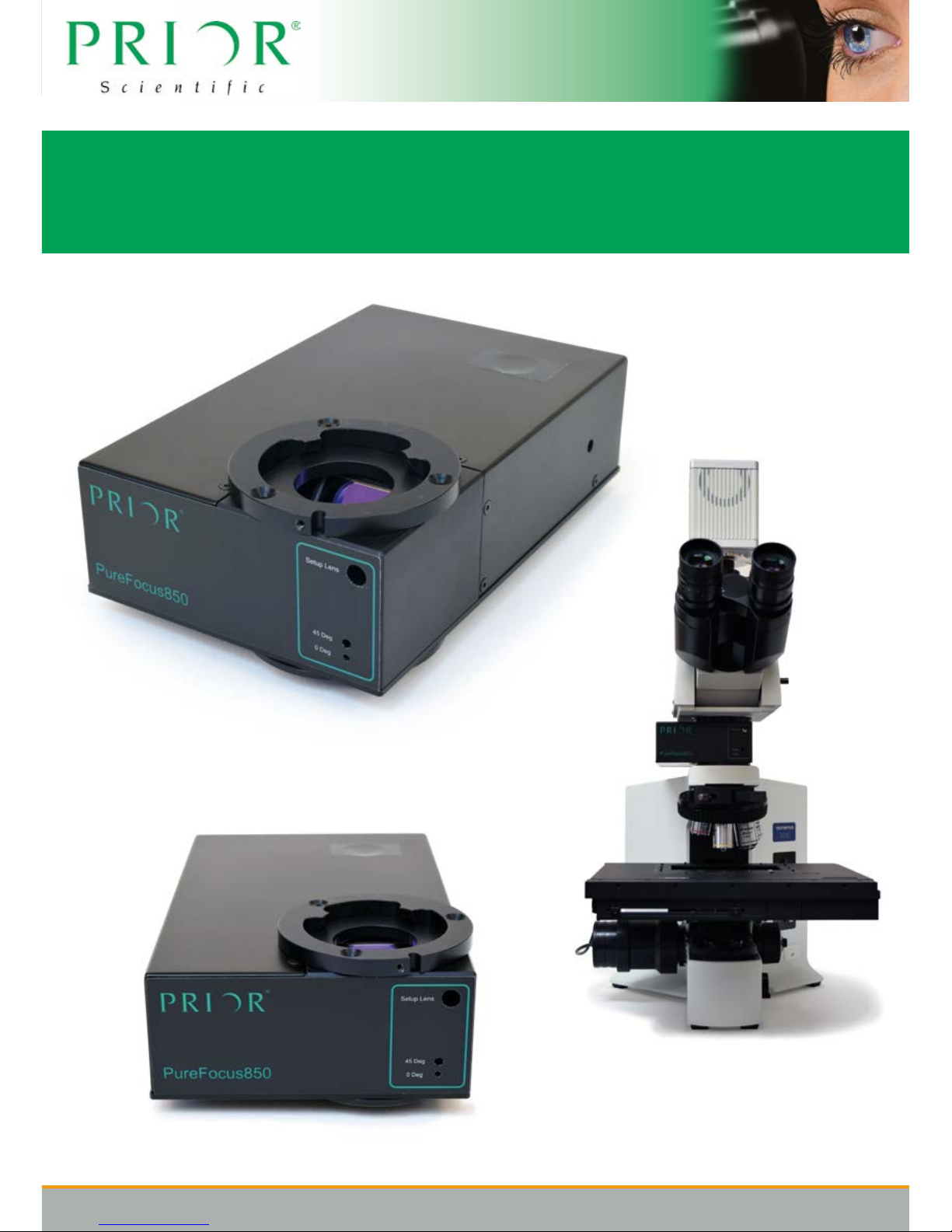
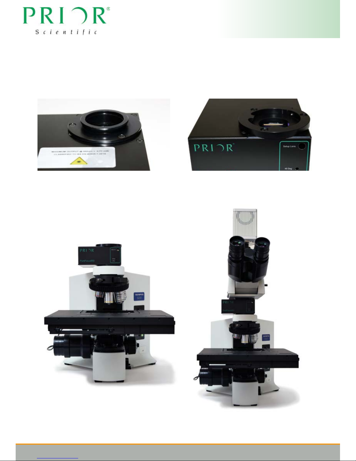
Section 2
Product description
The Prior Scientic PureFocus850 is an advanced, integrated, unit comprising of an IR laser diode,
precision optical components, detector and signal processing electronics with on-board micro
controller. The system allows optimum visual focus to be found and maintained on a microscope
system for a range of dierent sample types, microscope objectives and imaging methods.
The PureFocus system allows powerful automated autofocus functionality to be added to existing
microscope systems by installing the unit into the innity space (between objective and tube lens).
The system has been designed to t on many popular microscopes using innity corrected
optics, both upright and inverted types, using the relevant mounting kit. The PureFocus controller
outputs signals suitable for controlling piezo or motor focus drives and is compatible with Prior piezo
actuators and Prior stepper motors, by simply attaching to the ne focus knob of the microscope.
With the laser autofocus system the user has the ablitiy to work with a range of sample types with a
reective surface, including permanently mounted glass slides, live specimens in aqueous solution,
metallurgical, semiconductors and other samples with multiple reective layers. The system can also
work with plastic vessels such as well plates.
PureFocus works with both epi and transmitted illumination, and can be used for uorescence
applications with the 850nm source being outside of most uorescence bands.
A fully standalone system gives the end user the option of using the PureFocus controller with digipot,
display and buttons allowing all basic functionality option without the need for a host PC. The inbuilt
signal processing electronics generates focus correction information internally every 1ms allowing for
fast focus capture and tight closed loop action. For more advanced functionality PureFocus can be
fully remote controlled via USB communication, using our ASCII commands may be sent.

Version issue No. - 1.7
4
Section 3
Unpacking the system
This guide is an introduction to installing a Prior PureFocus850. Please note that instructions for specic
microscopes and parts may vary. Consult Prior Scientic if you are unsure.
PF850 PureFocus Controller, Head, Cables & PSU LF523 Lower Dovetail Flange Olympus BX60
PF100 PureFocus controller LF320 Flange Set (Nikon 150)
PF301 PureFocus controller OEM LF526 Upper Dovetail Flange Nikon Optiphot 150
PF185 PureFocus Head LF527 Lower Dovetail Flange Nikon Optiphot 150
PF209 Sample Set Up Slide LF312 Flange Set (Leica LB)
PF300 PureFocus Setup Camera Jig LF532 Upper Dovetail Flange Leica DM4000
PF200 PureFocus Alignment Target Type 1 LF533 Lower Dovetail Flange Leica DM4000
PF201 PureFocus Alignment Target Type 2 LF341 Autofocus Flanges (Zeiss Axioskop 2/40)
PF202 IX73 PureFocus Mounting Kit LF534 Upper Dovetail Flange Zeiss AxiosKop 2 / 40
PF203 IX71 PureFocus Mounting Kit LF535 Lower Dovetail Flange Zeiss AxiosKop 2 / 40
LF335 Flange Set (Olympus BX) PF208 IX73 Basic PureFocus Mounting Kit
LF522 Upper Dovetail Flange Olympus BX60 PF400 Connecting Cable
W3045 USB Cable
If for whatever reason you fail to recieve all the items you require please contact techsupport2@prior.com,
where a member of sta will happily help with your issue.
Please note you will have to download the GUI from the prior.com website.
Downloads are free and additional infomation is available on our website on how to use the GUI.
More to PRIOR than meets the eye
For more information visit www.prior.com
5
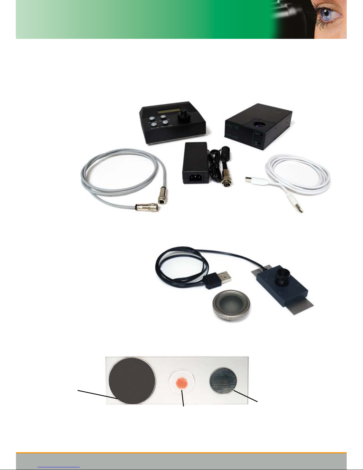
1. PF system
In your shipment you should recieve:
PF head
PF controller
Connecting cable
Power supply
USB cable
Stepper motor (optional)
Piezo BNC cable (optional)
Dovetail kit (optional)
Inverted microscope kit (optional)
2. Alignment kit
Alignment target
IR alignment camera
3. Setup slide
Set up mirror
Sample for life science
Sample for material
science
The sample for life science consists of a thin specimen permanently mounted under a standard #1.5
coverslip.
The sample for material science consists of a a bare piece of stainless steel.
PF head
PF controller
Connecting
cable
Power
Supply
USB cable
Version issue No. - 1.7
6
Section 4
Introduction
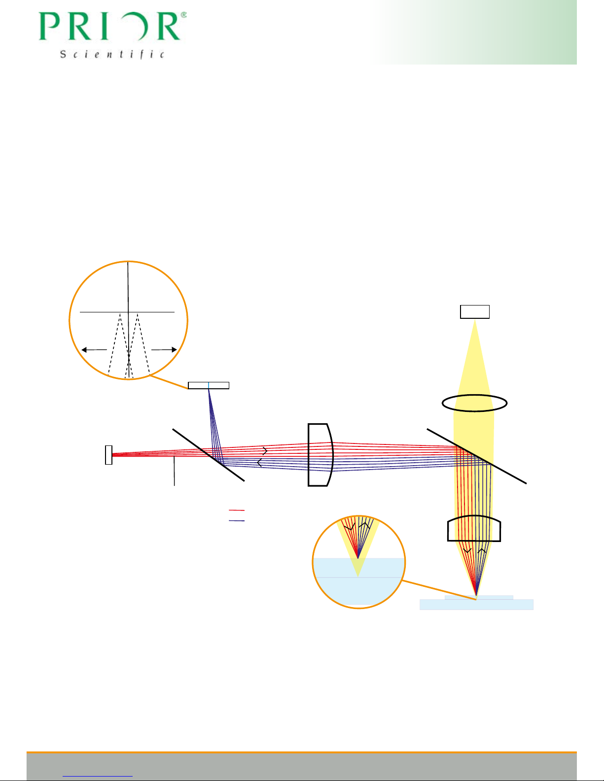
4.1 Working principle
The Pure Focus operates using a sensor with mutiple pixels. Half the aperture of a collimated laser
beam is blocked via a knife edge and directed into the back of the microscope objective. The laser
light is focussed to a line on a reective surface at the sample and then reected back through the
objective and directed towards the sensor forming a corresponding line on the sensor at the centre
point. Due to half the aperture of the laser being blocked, motion of the reective sample up or down
causes this line to move either left or right on the sensor, giving information to automatically control the
focus of the microscope and keep the sample in focus.
Knife Blade
Beamsplitter
Laser Diode Source
Adjustable
Collimating Lens
Line Sensor
Dichroic Mirror
Objective Lens
Sample
Incident Beam
Reflected Beam
Out of focus Out of focus
Tube
Lens
Camera / eye piece
Due to the nature of the line sensor there is freedom to choose what range of pixels either side of the
centre point are used in calculating a focus error signal. This allows the rejection of reections from
spurious reective surfaces and oers great exibility when dealing with various dierent samples.
More to PRIOR than meets the eye
For more information visit www.prior.com
7
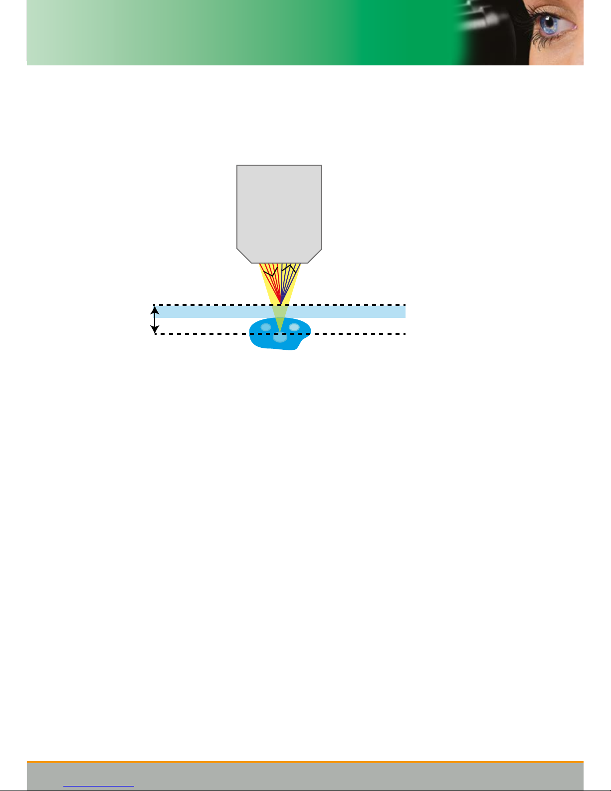
The addition of adjustable laser collimation also allows the reective surface, used by PureFocus
for holding focus, to be located at a dierent plane to the microscopes imaging plane, where the
specimen resides. This allows for continuously variable osets to be added. This is especially useful
when dealing with biological samples where the specimen will reside under a coverslip, which has a
reective top surface.
Offset
Reflective plane
Imaging plane
20x/0.75
To form a focus error signal rstly the system sums the pixel values to the left and right of a dened
centre pixel on the sensor, these summations are named A and B respectively. The number of
pixels that are summed either side of the centre to generate A and B can be chosen. The command
PINHOLE allows the centre point and width to be set. The sensor has 1500 pixels so the maximum
possible width is 750 pixels, for a centre point in the exact centre of the sensor at pixel 750.
The position signal is then computed as
POS = (A-B)/(A+B)
which is a signal that nominally swings between -1 and +1. A target value is subtracted from the
position signal to form an error signal
ERROR = TARGET - POS = TARGET - (A-B)/(A+B)
This signal is fed into a PID controller and the output of this controller is sent to either the Prior stepper
motor or to an analogue voltage for driving an external piezo controller.
PureFocus also computes two further values from the line sensor, C and D, which aid in operation.
C is simply the value of the centre pixel. D is the summation of pixels across an arbitrary section of
the sensor, which is settable to any range of pixels. This D value is useful for detecting if the system
is focussed to the correct interface when working with samples that contain more than one reective
surface.

Version issue No. - 1.7
8
4.2 Sample types
PureFocus works with a variety of dierent samples:
Permanently mounted slides
These are specimens that are xed in a mounting media usually with refractive index matched to the
glass coverslip (n≈1.5). When working with dry objectives with such samples a reective signal is
only available from the outside of the coverslip. It is recommended to work with #1.5 coverslips with
PureFocus.
If the specimen is high contrast (such as a stained section) as you scan over the slide, the level
of scattered/reected light from the inside of the coverslip where the specimen resides can vary
signicantly. In such cases it is benecial to position the knife edge `past-centre’ so more than half of
the laser line is blocked. This can be achieved by turning the knife edge screw (4) one additional turn
anticlockwise.
When working with water immersion objectives with such samples, a weaker reective signal is still
available from the outside of the coverslip. However, when working with oil immersion objectives
with such samples no reective signal will be available to work with. In these scenarios it may still be
possible to use a very weak reective signal from one of the interfaces to hold focus
Specimens in aqueous solution
These are specimens that sit on the inside face of a vessel or coverslip in a solution usually with
refractive index similar to water (n≈1.3). When working with dry objectives with such samples a strong
reective signal is available from the outside the coverslip/vessel and a weak reective signal is
available from the inside of the coverslip/vessel.
By default PureFocus works with the strong outside signal, however it does have capability in certain
conditions to work with the inside signal (See Operation - Section 6). It is recommended to work
with #1.5 coverslips/glass bottoms with PureFocus, although performance is possible with higher
thicknesses depending on the objective being used.
When working with water immersion objectives with such samples, reective signals are still available
from the outside and inside of the coverslip/vessel. However, when working with oil immersion
objectives with such samples there is only a reective signal from the inside of the coverslip/vessel.
Purely reective samples
For samples such as thick glasses, mirrors, metals and silicone wafers there will be a strong isolated
reection signal available.
Other samples with multiple reective layers
In a similar manner to biological samples, some industrial samples may consist of dierent layers
of reective material/coating, one example being an LCD panel. Depending on the thicknesses and
reectivities involved PureFocus may also be compatible with these samples

More to PRIOR than meets the eye
For more information visit www.prior.com
9
4.3 Types of microscope system
PureFocus works on a range of dierent microscopes which use innity corrected optics. The
PureFocus head sits in the innity space of the optical path between the objective and tube lens.
Inverted microscopes
On inverted microscopes where the objective moves and the sample is xed the PureFocus head
sits directly behind the objective nosepiece moving with the objective nosepiece as it changes focus
height, this is achieved using an mounting kit for the particular microscope being used.
Upright microscopes
On upright microscopes where the objective is xed and the sample moves the PureFocus head
can sit at any position in the innity space of the optical path, remaining xed to the body of the
microscope using a dovetail kit for the particular microscope being used.
Transmitted light/brighteld illumination
When working with transmitted light illumination, PureFocus could be susceptible to illumination light
reaching its sensor. In this case it is better to set the illumination light source to the lowest brightness
that still gives an acceptable image at the camera/eye pieces.
Reected light/epi illumination and uorescence
For reected light illumination and uorescent applications it is benecial to position the PureFocus
head below beam splitters and uorescence lter cubes which could attenuate or prevent the 850nm
PureFocus light reaching the sample
Phase contrast and DIC
PureFocus can work with a range of phase contrast objectives. The polarisation optics in DIC
microscopes must be positioned after the PureFocus head to be compatible.
Version issue No. - 1.7
10
Section 5
Installation
5.1 Installing the head
Install the microscope dovetail kit onto the PureFocus head unit. For information on installation for
inverted microscopes please contact a Prior representative.
Mount the PureFocus head unit onto the microscope between the objectives and tube lens, in the
ininity space (there are multiple places it could be mounted in the innity space depending on the
microscope).
More to PRIOR than meets the eye
For more information visit www.prior.com
11
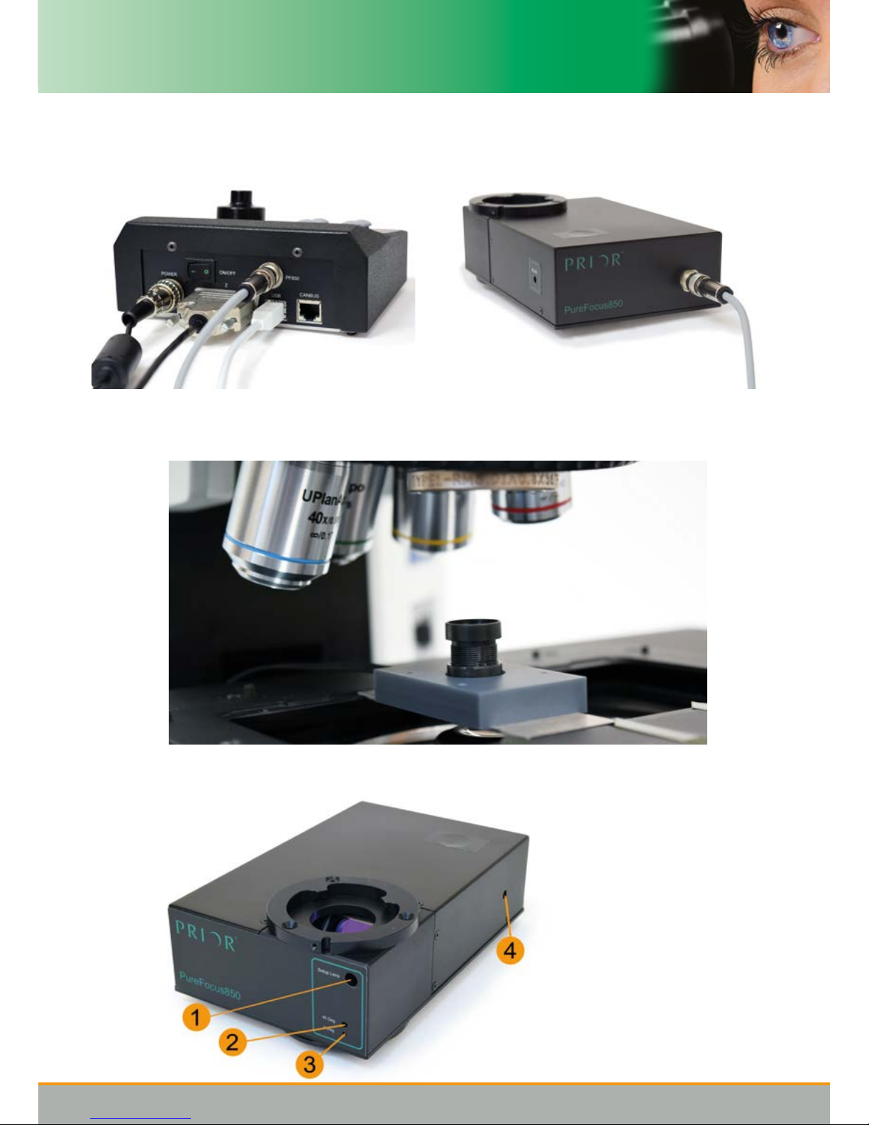
5.2 Initalizing the head
1. Connect cables
2. Insert IR alignment target into nosepiece and mount the setup camera onto the microscope
stage
3. Turn Allen screw labelled Blade (4) clockwise to the limit to remove knife edge from beam path
4. Turn on the control box and run the PureFocus850.exe Graphical User Interface (GUI)*
*Please note you will have to
download the GUI from the
prior.com website.
Downloads are free and
additional infomation is
available on our website on
how to use the GUI.
1. Setup Lens adjustment
2. Dichroic adjustment
(Nominal 45°)
3. Dichroic adjustment
(Nominal 0°)
4. Blade adjustment
Version issue No. - 1.7
12
5. Reset the PureFocus (Settings > Factory Reset) to ensure all settings are at factory defaults
6. Set laser power to 4000 (Laser > Set Power , value 4000)
7. In the main GUI, set the oset lens (Oset>Goto Limit)
8. Place the Camera alignment tool on the stage and move the IR alignment nosepiece target into
position. Using the camera software, camera.exe* check that the camera is focused onto the
front surface of the IR target. Adjust the camera focus lens if required.
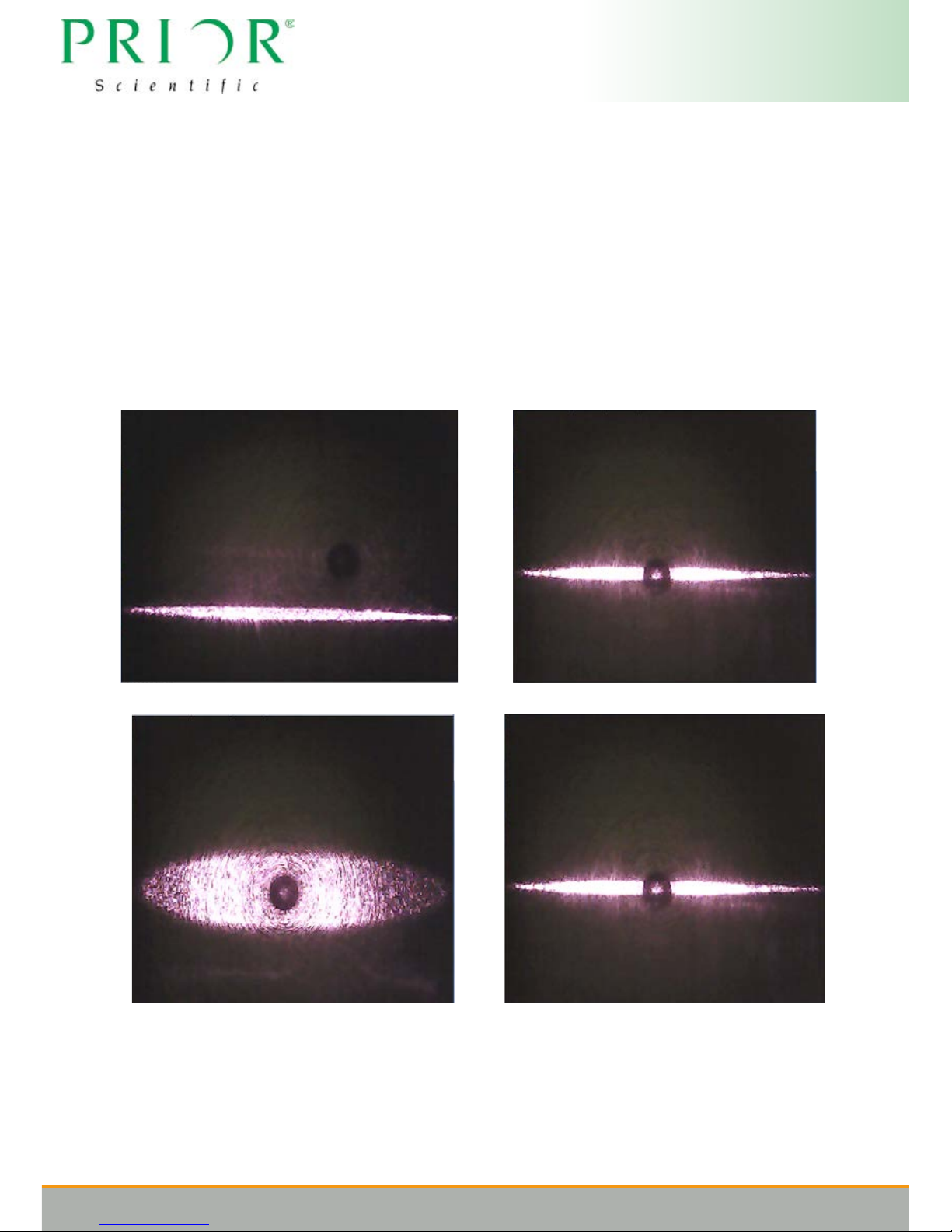
9. For some microscopes an adjustment of the oset may be required to get a good view of the
laser line across the camera eld of view, similar to the below images
10. Align the laser line with the centre of the target using the dichroic adjustment screws (2 and 3).
Please note that the laser line orientation may vary depending on the orientation of the camera
on the stage.
11. Adjust the setup lens screw (1) to get the sharpest line on the target:
12. Remove the alignment target and put a 10x objective in the nosepiece and position the objective
over the mirror section of the setup slide
13. Set Oset lens back to default position (Oset>Goto Factory Home)
14. Using your camera imaging software and PureFocus controller nob, or microscope manual
Bad Good
*camera.exe can be downloaded from the prior.com website along with the GUI software
 Loading...