

Prior NanoScan OP400 Quick Start Instructions
NANOSCAN OP400 QUICK START INSTRUCTIONS
PLEASE READ THE INSTRUCTIONS BEFORE
ATTEMPTING TO USE THE NANOSCAN OP400 SYSTEM
• Save this manual as it contains important safety information and operating instructions.
• Before using the system, please follow and adhere to all warnings, safety and operating instructions located
on the product and in this user manual.
• Do not expose the product to open flames, extreme hot or cold temperatures, water or moisture.
• Do not allow objects to fall on or liquids to spill on the product.
• Connect the AC power cord only to designated power sources as marked on the product.
• Make sure the electrical cord is located so that it will not be subject to damage.
• To reduce the risk of damage, unplug the product from the power source before connecting the components together.
• DANGER - never alter the AC cord or plug. If the plug will not fit into the outlet, have a proper outlet installed
by a qualified electrician.
• Use only the proper type of power supply cord set (provided with the system) for this unit.
• Do not attempt to disassemble the product. Doing so will void the warranty. This product does not contain
consumer serviceable components. Service should be performed by authorized service centers.
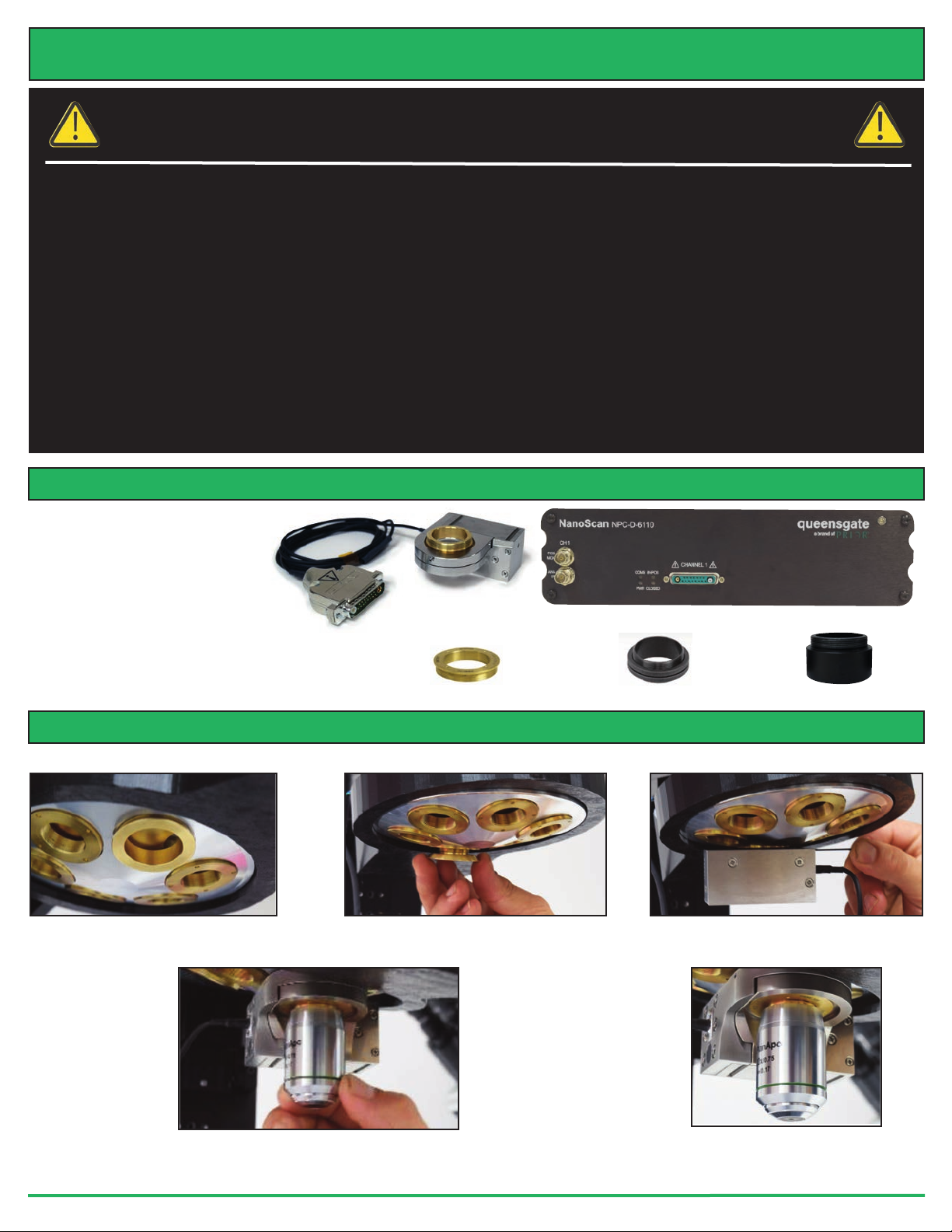
IDENTIFYINGYOURSYSTEM COMPONENTS
The standard NanoScan OP400
system consists of:
(1)
- NanoScan OP400
Piezo Objective Scanner
(1) - NPC-D-6110 Controller
(1) - Microscope Thread Adapter
(1) - 1.3mm (0.05 inch) Hex Key
(1) - Objective Lens Thread Adapter (optional)
(1) - Objective Lens Spacers (optional)
NanoScan OP400 Piezo
Objective Scanner
Microscope Thread Adapter
NPC-D-6110 Controller
Objective Lens Thread Adapter
Parfocal Objective Spacer
INSTALLINGYOURSYSTEM
Please take care with the cabling. Under no circumstances use the cabling to hold the stage.
STEP 1: Select the position for the
OP400 on the nosepiece.
STEP 2: Insert the microscope thread
adapter.
STEP 3: Connect the OP400 to the
nosepiece. Tighten with the hex key.
STEP 4: Insert the objective lens using the appropriate objective lens adapter. Note no
adapter is necessary for M32. Other objectives can be inserted into the nose piece using
option parfocal spacers.
www.prior.com
STEP 5: The OP400 unit is
now properly installed.
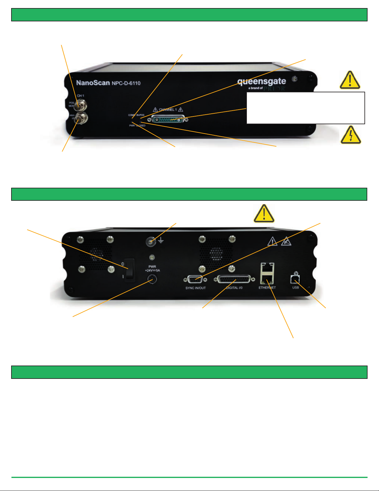
CONNECTING YOUR SYSTEM - FRONTOFUNIT
POS MON connector Analogue position
monitor (POS MON) output BNC
connector(s) – single ended output(s).
Indicates the state of the controller communications with
COMS Indicator LED
the connected computer. Not lit = No communications
taking place. GREEN lit or flashing =
Communications are taking place
Indicates the status of the stage position in
IN POS Indicator LED
CLOSED loop mode. ORANGE = Stage settings
being loaded on connection. OFF = Stage has not
reached the desired position. GREEN = Stage has
reached the desired position (within specified limits)
Nano Mechanism Connector – connect the OP400 to
this position. This provides the stage piezo HV supply,
power for calibration EEPROM and measuring
signals for capacitive sensor operation. NOTE High
Voltage present on connector – up to 160VDC
ANA I/P” connector Analogue
command input BNC connector(s) – single
ended input(s). Signal used to control the
stage position
ready (can take up to 30 seconds). GREEN steady =
CONNECTING YOUR SYSTEM - BACKOFUNIT
Provides additional product ground to help reduce interference of
background electrical noise. Do not raise above 0V ground potential
On/Off switch
Power Connector 4 pin miniDIN with screen Input
+24V dc ±0.75V @ 5A Provides power to the
controller electronics. ONLY connect an approved
power supply.
Indicates the power status and functionality of the
Power Indicator LED
product. RED steady = Controller configuring/not
Controller powered and ready for operation
Earth Stud - M4 threaded stud
Provides digital inputs and outputs for interfacing controller to
external equipment. 25 pin D-type socket; 5V TTL input/output
MUST use shielded cable.
TRIG Input
TRIG Output
IN_POS Output
Stepped Input
Stepped Output Interface Connector
Indicates the status of the stage control Loop
CLOSED INDICATOR LED
OFF = Stage NOT connected
ORANGE = Stage settings being loaded on connection
RED = Controller operating in OPEN loop mode
GREEN = Controller operating in CLOSED loop mode
YELLOW = Controller servo output frozen
Controller Synchronizing signals.
Only used to synchronize multiple
6000 controllers.
USB Connector Type B
Used to communicate with an
external computer.
Ethernet Connector
Dual connector master/slave
configuration. Used to communicate
with an external computer.
TURNINGON YOUR SYSTEM
1. Once the stage is mounted, connect stage to the controller ensuring that the connector screws are tightened to the controller
lock posts.
2. Connect Power to controller and USB interface to the PC.
3. Switch ON controller using switch on rear panel. After approx. 30 seconds, the relevant stage channel should show two green
lights (Closed and IN-POS). This indicates the stage is operating in the CLOSED loop mode and IN-POS LED indicates stage has
reached position within a pre-defined band.
4. The analogue input and POS MON output is 0V to +10V giving a scale factor of 40µ/volt. The analogue input is enabled by
default. The Scale Factor is in microns per volt. 50 microns per volt for the OP400.
5. The system has 8 memory positions for PID settling (accessible via the USB interface). The system has been shipped with
optimized settings for different objective loads, resolution and step settle requirements. The default setting has been optimized for
loads from 150g to 500g. To change to the other settings it is necessary to connect to a computer, the next section demonstrates
how to change to other settings. Do not change settings too fast for load used or damage to the unit may occur.
www.prior.com
 Loading...