

Page 1

Operating Instructions
PriorLux POL
™
Advanced Polarising
Microscope
Page 2

Page 3

PriorLux POL™ 1
q~ДдЙ=зС=`зенЙенл=
1. Introduction 2
2. Unpacking 2
3. Specifications 3
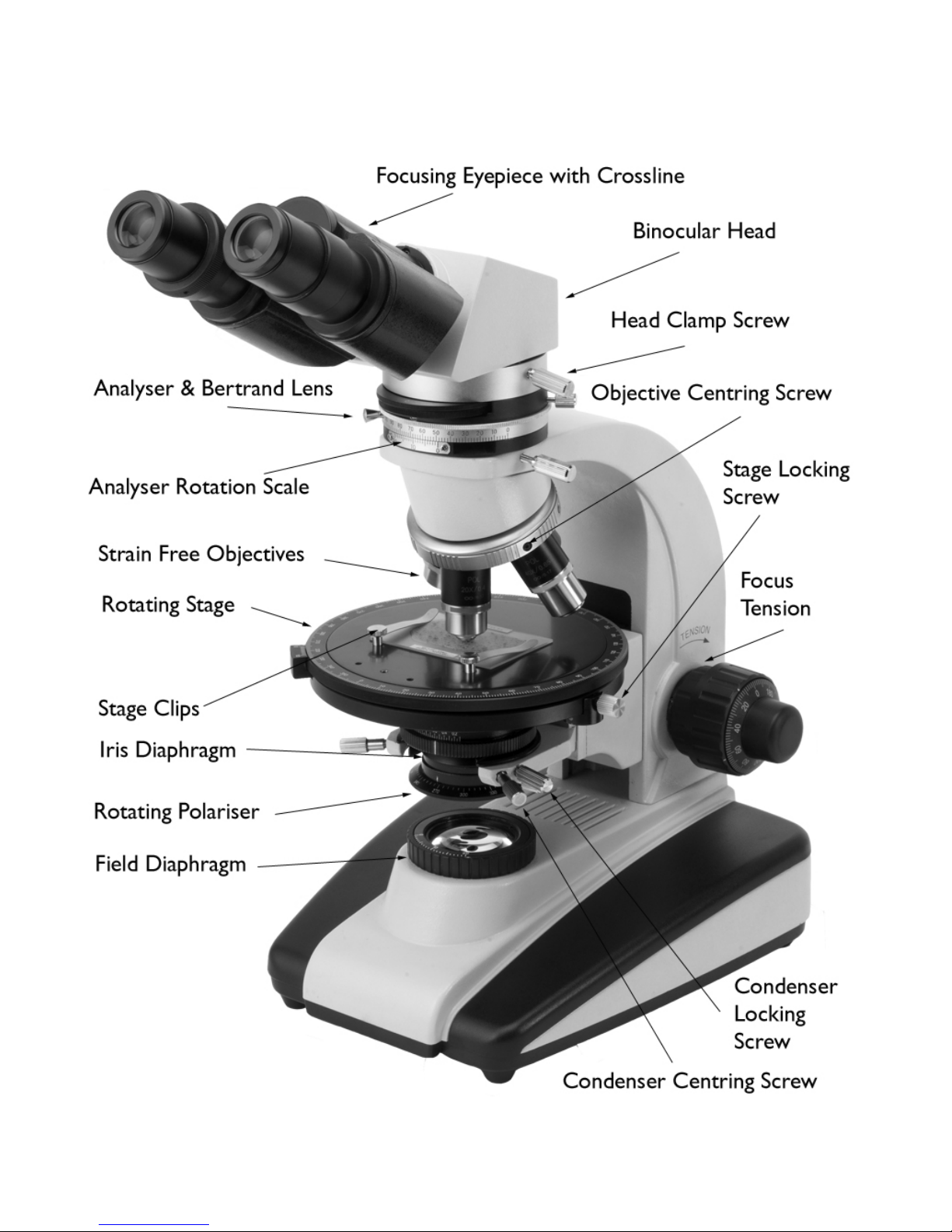
4. Component Parts 4
5. Electrical Connections & Safety 5
6. Setting Up 5
7. Setting Köhler Illumination 6
8. Cleaning Objectives 7
9. Centring the Objectives 7
10. Attaching the Mechanical XY Stage 8
11. Observations Between Crossed Polars 8
12.
Conoscopic Observations 8
13.
Bertrand Lens 9
14.
Use of Compensators 9
15.
Using a Camera 10
16.
Bulb Replacement and Adjustment 12
17.
Fuse Location 13
18.
Spare Parts 13
19.
Safety Precautions 14
20.
Regulatory Compliance 15
Page 4

2 Prior Scientific
1. Introduction
The PriorLux POL upright compound polarised light microscope is a high quality instrument
equipped with high resolution, chromatically corrected strain-free optics for excellent image
quality in polarised light applications. The robust construction and hard wearing materials
ensure long lasting and trouble free operation. The instrument can be used with a number of
supplied accessories including ¼ and compensation plates, quartz wedge, attachable
mechanical XY stage and eyepiece graticule with stage micrometer.
For documentation the instrument is available with a trinocular head which permits mounting
of a video or digital camera system.
2. Unpacking
The PriorLux POL is shipped in protective bags within a pre-formed container. Each
component should be carefully unpacked and checked, cutting rather than tearing the plastic
bags. The head (binocular or trinocular) should be fitted to the dovetail on top of the stand
and locked in place with the head locking screw. The eyepieces then just drop into the
eyepiece tubes at the front of the head, these should be pushed in as far as they will go.
Remove each objective lens from its protective “pot” and screw into the free positions on the
nosepiece. Move the stage and the condenser carrier to the highest position and insert the
condenser from underneath with the diaphragm control facing to the front. This is locked in
position with the clamping screw, which is fitted from the side.
Page 5

PriorLux POL™ 3
3. Specifications
Eyepieces 10x 20mm field of view
Condenser Abbe NA 1.25 with iris diaphragm and filter holder
Mechanical Stage 360 Degree rotation, 1 degree increments
Focusing
Mechanism
Co-axial fine and coarse adjustment with tension control and focus
stop
Viewing Head Interpupillary distance 55-75mm
Kohler Illumination 12V 30W halogen lamp with variable brightness control
Power Supply 220/240 VAC 50/60Hz or 110/120 VAC 50/60Hz.
Objectives Mag. NA Tube Length
4x 0.12 ∞
10x 0.25 ∞
20x 0.45 ∞
40x (S) 0.65 ∞
60x (S) 0.85 ∞
Page 6
4 Prior Scientific
4. Component Parts
Page 7

PriorLux POL™ 5
5. Electrical Connection and Safety
Stands are supplied with an operating voltage of either 220/240 VAC 50/60Hz or 110/120
VAC 50/60Hz. The instrument is supplied with a power lead complete with appropriate
plug for mains connection. UK plugs are fitted with a 3A fuse. This should only be replaced
with a similarly rated fuse. The instrument should ALWAYS be switched off and isolated
from the mains before any lamp or fuse is changed. The internal fuse is a T1.25A type
(replacement code W335). If necessary, replace only with this type of fuse.
6. Setting Up
Connect the power cable to the base of the microscope, at the rear, and before switching on
the power, reduce the lamp intensity control to its minimum setting. After switching on, the
intensity should be increased to a comfortable level. This procedure should be reversed
before switching off. Following this method will considerably prolong the life of the bulb.
Binocular/Trinocular Head
Interpupiliary distance should be set by rotating both eyepiece tubes in an arc until the two
images coincide and the view is perfectly circular to both eyes. Note the value on the scale
between the eyepieces so that the position can quickly be regained for future viewing. Place
a specimen on the stage and focus the image while looking through only the right eyepiece.
When the specimen is in focus close the right eye and adjust the dioptre on the left eyepiece
so that the image is perfectly focused. The instrument is now balanced for your eyes.
Page 8

6 Prior Scientific
7. Setting Köhler Illumination
A. Follow the procedure in section 6 to set up the instrument for your eyesight.
B. With a specimen in sharp focus and the analyser in the “out” position using the 10x
objective, close the field diaphragm until it impinges on the field of view, Figure 1,
Picture A.
Figure 1
C. Focus the condenser using the side mounted rack and pinion controls until the leaves
of the diaphragm are in sharp focus, Figure 1, Picture B.
D. Using the condenser centration controls move the diaphragm into the centre of the
field of view, it may help to open it until it is nearly touching the outside of the field
to attain perfect centration, Figure 1, Pictures C & D.
E. Fully open the field diaphragm.
F. Fully open the condenser diaphragm and then slowly close it until you see the
contrast within the image increase. If you then remove an eyepiece and look directly
down the tube from a distance of 20-30cm you should see an image similar to
picture D in Figure 1. The aim here is to have the “bright” area occupying
approximately 70% of the total field. The amount it occupies will change dependant
on the objective lens in use. If you have set up the instrument using the 10x
objective (recommended) then as you increase the magnification this diaphragm will
need opening to optimise the contrast and resolution. Often it is set for the
objective which is either most frequently used or most critical in terms of resolution
and left in that position
Page 9

PriorLux POL™ 7
8. Cleaning Objectives
It is critical that the front lens of each objective is kept clean and free of contamination. Any
dust or dried immersion oil will seriously affect the image quality attainable with that
objective. If contamination is suspected then the easiest way to confirm this is by removing
the objective lens and examining the front lens using the eyepiece. To do this take out one
of the eyepieces, turn it around so that you are looking the wrong way through it and move
it towards the front of the objective until you can focus on the front lens. This will clearly
show any contamination. To remove dirt and oil a lens cloth, lens tissue or cotton bud
dampened with industrial alcohol can be used. A spiral motion starting from the centre of
the lens moving to the outside is the best way of achieving a thoroughly clean surface
9. Centring the Objectives
The lowest power objective is mounted in a fixed position and therefore centration of this
particular lens is not user adjustable.
All other powers are mounted in positions with adjustment screws fitted into the nosepiece
above to enable the end user to make adjustments to the alignment of the objective lens. To
re-align an objective which is obviously misaligned with the centre of rotation, as indicated by
the crossline in the eyepiece the following procedure should be followed.
Insert the two supplied centring keys into the adjustment screw sockets above the objective
in the knurled ring of the nosepiece. Rotate the stage and observe that part of the specimen
upon which the specimen appears to rotate. If necessary move the specimen until the centre
of rotation coincides with a feature in the specimen that is easily recognised.
Now by means of the centring screws move the feature until it coincides with the
intersection of the crossline in the eyepiece. The stage must remain stationary while the
objective is being centred. Once the identifiable feature has been aligned with the crossline
rotate the stage to check that the axis of rotation is now coincident with the intersection of
the crossline.
Page 10

8 Prior Scientific
10. Attaching the Mechanical XY Stage
The attachable mechanical stage enables smooth specimen movement along with precise repositioning courtesy of the vernier scales.
Firstly remove the sprung stage clips and retain for future use. The mechanical stage then
simply screws into the tapped hole provided in the top plate of the stage.
11. Observations Between Crossed Polars
Before using crossed polars, always remove the specimen from the stage and check that
extinction is complete when the analyser is “in”. Both polariser (below the sub-stage
condenser) and analyser (underneath the viewing head) are rotating. It is recommended that
the polariser is set to the reference position and then the analyser rotated so that it is at
ninety degrees to it. At this point extinction will be achieved.
12. Conoscopic Observation
A microscope is used conoscopically when the back focal plane of the objective is observed
using the Bertrand lens. In petrology birefringent specimens can produce interference
patterns in this plane that are of considerable importance. The figures can be either uniaxial
or biaxial, and can only be properly observed when objectives of high aperture are used and
the full aperture of the condenser is utilised, that is, with the upper lens in position and the
iris diaphragm opened to the full. The front lens of the condenser should be as close to the
specimen as possible. A uniaxial crystal gives a characteristic “ring and brush” whilst a biaxial
crystal gives a figure with two “eyes” or metalopes, which rotate as the specimen rotates.
The complete symmetrical figure is only obtained when the section is perpendicular to the
acute bisectrix of the optic axes of the crystal. The angle between the optic axes of a biaxial
crystal can be calculated by the method due to Mallard. Measurements between the
metalopes can be calibrated against the figure obtained from a known crystal such as quartz.
Page 11

PriorLux POL™ 9
13. Bertrand Lens
The Bertrand lens is built into the microscope and enables the user to switch quickly
between orthoscopic (Bertrand lens out) and conoscopic (Bertrand lens in).
14. Use of Compensators
The slot in the body of the microscope between the nosepiece and the viewing head of the
microscope, set at 45
o
to the N-S axis is for the insertion of the supplied compensators.
These should be inserted when the colour of the specimen is at its maximum, that is, when it
is turned 45
o
from the position of extinction. Compensators provided for use with the
PriorLux POL are DIN standard.
Quartz Wedge
When a wedge of uniaxial crystal of quartz, cut parallel to the optic axis is inserted into the
compensator slot between crossed polars a series of interference colours will be observed.
The retardation caused by the specimen can be assessed by its compensation of an order of
colour of the wedge. The Prior quartz wedges are mounted length “fast” and when the
interference colour of a mineral specimen is compensated by placing the slow of the wedge
on the fast of the specimen, the position of the colour in Newton’s scale can be ascertained.
The quartz wedge is wedge is used when the birefringence specimen and the interference
colours are high.
Sensitive Tint Plate
The type of compensator is often also referred to as a first order red compensator. It is cut
to give an interference colour at a very sensitive part of the colour scale. When inserted
between crossed polars the fast and slow direction of a birefringent material can be
determined. The specimen is rotated until the colour order is raised or lowered by the
maximum amount. If the colour raised, the fast direction is coincident with the fast direction
of the sensitive tint plate.
Page 12

10 Prior Scientific
Quarter Wave Plate
This compensator gives retardation of ¼ wavelength between the vibration directions.
When the specimen is rotated, with the quarter wave plate inserted between crossed polars
the fast and slow directions of the specimen can be found by the rise and fall of the order of
colour. A maximum rise of colour will occur when the fast direction of the quarter wave
plate coincides with the fast direction of the specimen.
15. Using a Camera
The PriorLab / PriorLux microscopes, when fitted with a trinocular head, can be used with a
range of cameras for documentation purposes. Video cameras, both analogue and digital
provide ‘moving’ pictures for more advanced imaging applications, while digital ‘still’ cameras
can be used for basic image capture.
Detailed instructions for the operation of the selected video or digital camera are supplied
with the camera.
Assembly Video Cameras
A. Screw the c-mount adapter (part no. WXCM1 1.0x or WXCM050 0.5x) to the
video camera
B. Loosen the knurled silver screw on the c-mount adapter and insert the adapter
with the attached camera into the top of the photo tube on the trinocular head
C. Tighten the screw to secure the assembly
D. Connect camera to a PC, framegrabber or analogue monitor as required
E. To view the image via the camera, pull out the light path selector on the side of
the trinocular head. This diverts 80% of the light to the camera and 20% to the
eyepieces
Assembly Digital Cameras
This is similar to the assembly of video cameras above, but a digital coupler (part no.
MZO1403 suitable for the Nikon Coolpix 4500 or the MZO5503 suitable for the Nikon
Coolpix 5400) and a step down ring (part no. W3000) may also be required depending on
the camera model used.
For more detailed set up information refer to the literature supplied with the camera.
Page 13

PriorLux POL™ 11
Page 14

12 Prior Scientific
16. Bulb Replacement and Adjustment
Halogen bulbs have a finite life and will need replacing from time to time. Replacement bulbs,
part number W3257, are available from Prior Scientific.
To change the bulb;
A. Switch off the microscope and isolate from the mains electrical supply
B. Remove the eyepieces from the viewing head to prevent them falling out
C. Lay the microscope on its back to gain access to the base plate
D. Loosen the screw which holds the lamp cover to the base plate
E. Open the lamp cover to expose the bulb holder
F. Remove the old bulb and replace it with
the correct replacement bulb (part no.
W3257, 12V 30W push fit double pin type)
by sliding upwards in its holder. Do not
handle the bulb with bare fingers, hold it in
a piece of paper tissue or in the bulb
wrapping material. Finger marks can cause
contamination which blackens the bulb
when it is switched on. If the bulb has been
touched with the fingers, clean it with a
tissue moistened with alcohol.
Page 15

PriorLux POL™ 13
17. Fuse Location
The fuse is located on the base towards the front right corner of the instrument.
18. Spare Parts
W3257 – Spare bulb 12V 30W Halogen
W335 – Fuse T1.25A
Page 16

14 Prior Scientific
19. Safety Precautions
The following symbols have been used on this microscope
These symbols are found next to the bulb access door on the underside of the
instru ment.
Warning High voltage, disconnect po w er supply before changing the bulb.
This symbol is located next to the bulb access door on the underside of the
instrument
Caution Hot surface, allow surface and bulb to cool down completely before
attempting to change the bulb.
Page 17

PriorLux POL™ 15
20. Regulatory Compliance
Complies to the following standards
EN/IEC 61010-1:2001 Safety requirements for electrical equipment for measurement,
control, and laboratory use – part 1: General requirements
EN61326:1997 (+A1/A2/A3) Electrical equipment for measurement, control and
laboratory use – EMC requirements
Class B emmisions
EN61326:1997 (+A1/A2/A3) Electrical equipment for measurement, control and
laboratory use – EMC requirements
General immunity
CFR 47 : 2004 class A Code of federal regulations pt 15subpart B – Radio frequency
devices – unintentional radiators
Page 18

16 Prior Scientific
=
=
=
=
=
=
=
=
Specification subject to change without notification Part No. W2628 Issue B 10/05
Page 19

Page 20

 Loading...