

Page 1
Prio® Expert
MOD600
Direct Flow
Reverse Osmosis
Filtration System
(Pump Box Unit
with Auto-Flush,
Main Filtration Unit
with High-Production R.O. Membrane Set)
User’s Guide
Page 2
Before operating this appliance, please read the instructions carefully. You
may want to save this guide for your future reference. Failure to follow the
instructions or meet the operating requirements may lead to the product’s
failure, malfunction, property damage or personal injury.
Safety Warning
■
Plug the pump unit into an electrical outlet only aer you nish the installation.
■
Check if the voltage indicated on the pump unit corresponds to the local
mains voltage before you connect the appliance.
■
Do not use the pump unit if it is damaged in any way. Take it to an authorized service center for repair.
■
Do not open the pump unit. There are no serviceable parts inside.
■
When unplugging the pump unit from the mains, do not pull on the power
cord. Avoid touching the plug with wet hands.
■
Do not block air vents of the pump unit or place any items on it. Do not
place it near the sources of heat, radiators, etc. Do not place it in a tightly
closed space where it may overheat.
■
Keep the appliance out of reach of pets or other animals.
■
In case of leakage malfunction or water presence around the appliance
shut o the electrical power to the circuit rst, then pull the plug out of the
electrical outlet.
■
Remove the plug from the electrical outlet and shut o the inlet valve during your
vacations or other extended periods of time when the appliance is not in use.
■
Unplug the pump unit from the electrical outlet while servicing the main
ltration unit, and changing the membrane or lters.
■
Do not use the appliance if operating requirements such as water temperature/water pressure/electrical supply, etc. are not met. There may be other
local regulations to comply with.
■
Do not use the appliance with water that is microbiologically unsafe or of
unknown quality without adequate disinfection before or aer the system.
■
The pump unit was not designed to be used with power cord extenders,
power lters, external transformers, outlet splitters, etc.
■
Do not use the waste water produced by the appliance for drinking or cooking.
■
Never store or operate the appliance in direct sunlight.
■
This appliance is not intended for use by persons (including children) with
reduced physical, sensory or mental capabilities, or lack of experience and
knowledge, unless they have been given supervision or instruction concerning use of the appliance by a person responsible for their safety.
■
Children should be supervised to ensure that they do not play with the appliance.
■
At the end of its life, the appliance should be disposed o in an appropriate
manner.
Disposal
Old appliances still contain many recyclable materials. Therefore, please take
used unit to your retailer or recycling center so that it can be recycled.
2
Page 3

Description
Congratulations on your purchase of the Prio® Expert R.O. ltration system! With proper
installation and maintenance, it will provide you with high quality drinking water for many
years.
This R.O. system removes odor and most harmful substances such as heavy metal ions and
total dissolved solids from tap water making it tasty, fresh and vital.
This Reverse Osmosis ltration system consists of two units: the sophisticated pump box
with auto-ush control valve and powerful booster pump and the R.O. ltration unit with
high-production R.O. membrane. Together, they provide direct ow capability of water ltra-
tion in real time, eliminating the need of a water tank usually found on conventional systems.
Please familiarize yourself with the general concept behind the product and main modes of
operation.
Key Features:
■
Clean and safe drinking water right in your home. No need to transport and dispose of
bottled water any more.
■
Factory-preinstalled lters and membrane for faster and easier setup.
■
Filters and membrane quick-change housings for easy regular maintenance.
■
Compact and beautiful design.
■
Automatic ush valve: for peak performance and healthier membrane. 18 seconds of
powerful ush at the end of each water ltration cycle prevent the scale and debris build-
up on the membrane outer surface.
■
Powerful booster pump increases pressure to radically improve the performance and ef-
fectiveness of the R.O. unit in all three key areas: increases ltered water ow (production
rate), increases rejection rate (improves water purication quality), increases recovery
rate (decreases amount of waste water).
■
Prolongs the membrane and pre-lter(s) service life due to increased recovery rate.
■
Fully automatic operation of the pump box unit: just open the faucet and get clean water
instantly; automatic shut o and ush.
■
LED indicators: easily understand what the state of your R.O. unit is.
■
Split, exible installation possible where needed: install the pump box up to 50 feet away
from the R.O. unit itself. Useful for the situations like lack of space or lack of electrical
outlet under the sink, or moving the unit to more appropriate place.
■
Idling protection: if you forget to shut o the ltered water faucet for a long time the pump
will shut down automatically for you.
■
Full separation of electrical components from the membrane and lters of the main R.O.
unit makes the regular servicing of your R.O. machine both easy and safe: no need to
worry about electrical valves and wires while changing your water lters or membrane.
■
Quick ttings for easy tube connections and change of lters.
3
Page 4

Direct Flow R.O. Systems Benets:
Powerful booster pump and high-production R.O. membrane make it possible to build a high-
end direct ow R.O. machine that oers high performance and water quality.
■
Freshness of water ltered in real time. No more stale water from a tank.
■
Virtually unlimited ltered water production. While conventional systems with tanks are
limited by the tank capacity, and require prolonged timeouts to rell the tank, a direct ow
system is limited by the membrane ltration rate only.
■
Instant and sustained ltered water ow. It doesn’t depend on how full the tank is.
■
Space-saving, compact installation since tank is not needed.
■
Better water purication quality due to improved contaminant rejection rate.
■
Typically, up to three times less water is wasted per gallon of ltered water, compared to
the conventional tank and water storage systems, this is due to the much higher eciency
(recovery) rate. Saves you money and Planet Earth’s water resources!
■
Lower cost of ownership due to prolonged service life of pre-lters and membrane, which
is in turn a result of higher eciency rate: less water is treated overall by pre-lters and
the membrane for each gallon of permeate produced. This saves the capacity of pre-lters
and ensures either less frequent change necessity or better purication.
■
Less number of components leads to better reliability.
How It Works:
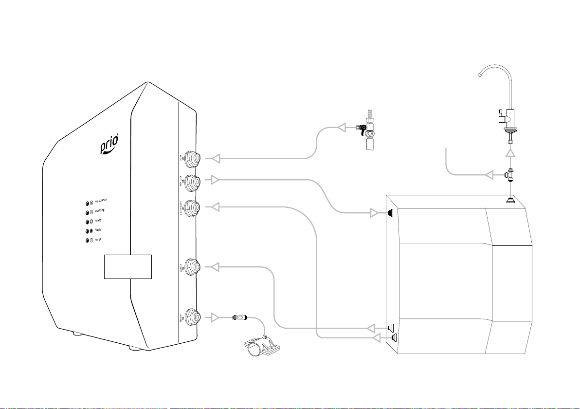
The MOD600 direct ow reverse osmosis system is a multi-stage automatic ltration machine.
The system consists of the two main units – the pump box and the R.O. unit – which are con-
nected with three tubes. This inter-unit connection distance is up to 50 . Water supply is done
through the inlet valve, ltered water is delivered through the faucet, and waste water is drained
through the drain saddle. Deta led connection scheme is shown on the following charts.
4
Page 5
Usually, both units – the pump box and the R.O. unit – are placed under the sink (such as in your
kitchen) and the ltered water facet is mounted on the sink deck near your normal water tap.
Aer installation, you will get clean water by simply opening the ltered water faucet. The
pump will turn on automatically and will produce ltered water in real time until you shut o
the faucet. At the end of each water production cycle the membrane will be ushed for 18
seconds, and then the system will shut o automatically.
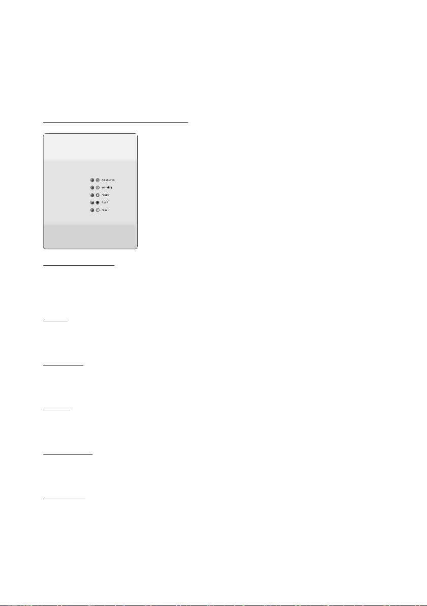
LED Indicators (on the Pump Box Unit):
■
No Source: there is no water in the inlet line or it’s pressure
is less than 7.25 psi (0.05 MPa). Make sure the inlet tube is
connected and not kinked, and the water inlet valve is open.
■
Working: the pump is working and connected R.O. unit is
producing the ltered water for you while ltered water fau-
cet is open. No action is required.
■
Ready: ltered water faucet is shut. The pump is o. No ac-
tion is required.
■
Flush: 18 s membrane ush is going. No action is required.
■
Reset: idling protection was triggered. The pump is o. To
restore normal operation power cycle the pump box unit.
Pressure Switches:
The pump box unit is equipped with low and high pressure switches. The low pressure switch
shuts o the pump when there is no inlet water or its pressure is too low. The high pressure
switch shuts o the pump when the ltered water faucet is turned o.
Pump:
The pump box unit is equipped with a low voltage booster pump powered by the included
transformer for safe operation.
Inlet Valve:
An adapter ball valve is included to be installed into the cold water supply line to feed water
to the pump box inlet.
Faucet:
Designer faucet for ltered water is included and usually mounted on the sink deck or countertop for dispensing the clean, ltered water from the ltered water outlet of the main R.O. unit.
Drain Saddle:
Fits a standard 1.5” diameter drain pipe to drain the waste water from the drain outlet of the
pump box.
Pre-Filters:
The main R.O. unit has two pre-lters: sediment pre-lter on the rst stage and activated
carbon pre-lter on the second stage. They provide initial ltration of the water and protect
the following thin lm composite R.O. membrane from dirt and aggressive chemicals such as
chlorine oen found in tap water.
5
Page 6

R.O. Membrane:
The third and main stage of the ltration is high-production R.O. membrane. It is “semi-permeable”, which means that it allows water to pass through but prevents dissolved particles
from passing through. It splits the feed water into two streams: clean water goes to the
post-lter and then onto the faucet. Waste water with rejected particles goes down the drain.
Post-Filter:
Last stage of ltration is an activated carbon post-lter and/or remineralization for ne con-
ditioning and keeping the extra freshness of your water.
Specication
Operating Requirements:
■
Minimum supply water pressure: 7.25 psi (0.05 MPa)
■
Maximum supply water pressure: 80 psi (0.55 MPa)
■
Minimum water temperature: 41 oF (5 oC)
■
Optimal water temperature: 59–77 oF (15–25 oC)
■
Maximum water temperature: 95 oF (35 oC) / up to 105 oF (40.5 oC) short-term
■
Ambient air temperature: 41–105 oF (5–40.5 oC)
■
Water source: tap water supply, chlorinated or non-chlorinated, bacteriologically safe
■
Supply water pH range: 4.0-11.0
■
Supply water turbidity: < 1 NTU
■
Supply water components: Hardness (CaCO3) <180 mg/L (<10.5 gpg), Iron <0.1 mg/L,
Manganese <0.05 mg/L, Hydrogen Sulde 0.00 mg/L
■
Maximum supply water TDS: 1000 ppm
■
Indoor use only.
■
Electrical input: AC 100-240V 50/60 Hz
■
Maximum length of the line between the pump unit and the membrane (“split installation”): 50 (15 m) (purchase of extra tubing may be required)
■
Tubing: ¼”
Performance:
Performance of the appliance such as ltered water delivery rate, rejection rate, etc. is highly
dependent on local conditions (inlet water pressure, temperature, TDS and degree of contamination, etc.) and R.O. system use pattern. Actual performance may vary.
■
Filtered water production rating: 400 gpd (1450 lpd) maximum
■
Filtered water delivery rate, typical: 0.159–0.330 gpm (0.6–1.25 l/min)
■
Membrane rejection rate1, typical: 90%
■
Recovery rate (system eciency2), typical: 50%
■
Drain water ow restrictor: 300 cc (ml/min) nominal, up to 450 cc in working mode, open
ow in ush mode.
■
Auto-ush duration: 18±5% s
1
For all dissolved solids combined as measured by TDS or conductivity meter.
2
Eciency rating means the percentage of the inuent water to the system that is available to the user as
reverse osmosis treated water under operating conditions that approximate typical daily usage.
6
Page 7

■
Idling protection: 120 minutes (the pump box unit shuts down the pump and goes into
‘reset required’ mode if working mode continuous duration reaches 2 hours without interruption)
Weight and Size:
Pump box unit:
Size (WDH), body only, excluding protrusions: 8.74 x 4.80 x 12.44” (222 x 122 x 316 mm)
Weight, without water and tubing: 8.6 lbs (3.9 kg)
R.O. ltration unit:
Size (WDH), body only, excluding protrusions: 13.46 x 4.92 x 14.80” (342 x 125 x 376 mm)
Weight, without water and tubing: 8.8 lbs (4.0 kg)
Warranty:
1 year limited warranty
Package Contents:
(1) The auto-ush booster pump box unit
(1) The R.O. ltration unit
(1) Adapter ball valve ⅜” x ⅜” x ¼” or ½” x ½” x ¼” (depending on market)
(1) Teon tape roll
(1) Faucet
(1) Drain saddle
(1) Wrench
(20 / 6 m) Water tubing ¼”
(1) ¼” x ¼” union check valve
(1) ¼” x ¼” x ¼” union tee tting
User’s guide
Installation
Notes:
1. Shut o the cold water supply under the sink or the location where the system will be
installed. If the existing valve is inoperable, the water supply to the house must be shut
o. Then, relieve the water pressure by opening the cold water tap. Do not connect the
system to hot water source.
2. Depending on your plumbing system and sink/countertop type you may need to use tools
like variable speed drill, drill bits, screw driver, wrench, etc. You may want to ask a profes-
sional service provider such as certied plumber to install the inlet valve adapter, faucet,
and drain saddle to assure a trouble-free setup.
3. During installation you will need to cut the supplied ¼” tubing into segments as needed.
Use your utility knife for that or similar tool. See the following charts to determine the
connection scheme and length of hoses necessary. You may need to purchase extra tubing
for far-reaching split or other corner case installations.
4. Do not connect the pump box unit to the electrical supply until the setup is completed.
5. With initial operation, check for leaks. If a leak is observed, verify that the tubing is pushed
into the quick tting far enough to seal the tubing against the O-ring and that the tubing
was cut at 90
o
.
7
Page 8
8
General connection scheme:
filtered
inlet
valve
water
faucet
X855
from inlet valve
to R.O. unit inlet
from filtered water outlet of the R.O. unit
from waste water outlet of the R.O. unit
to drain or
waste water
collection container
check valve
(optional)
drain saddle
R.O. unit
inlet
MOD600
waste water outlet
permeate outlet
to another
point-of-use
tee fitting
(optional)
Page 9
1
3
ut
No skewed cut!
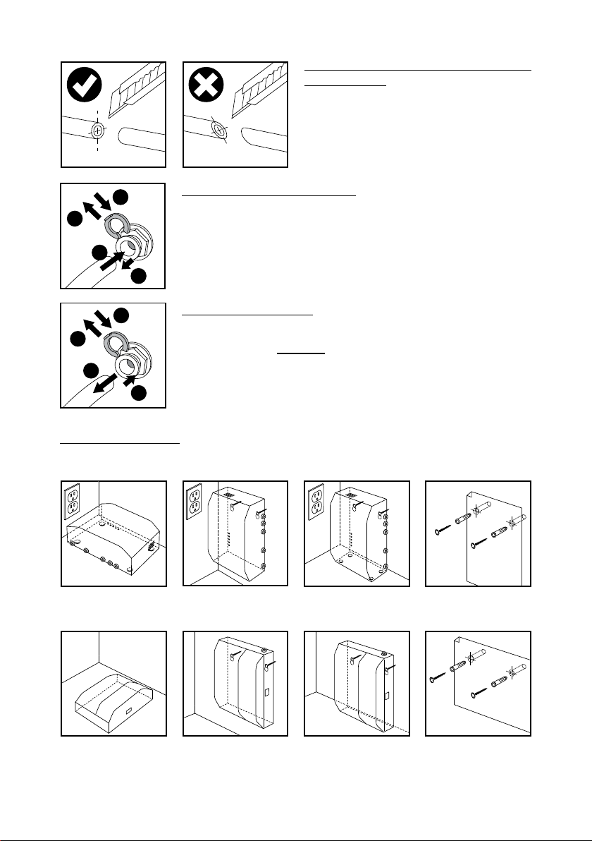
IMPORTANT: Cut Tubing At 90° to Ensure a
Watertight Seal:
4
1
2
3
4
1
3
2
Units Placement Guide:
Pump box unit
To Connect the Tubing to a Fitting:
1. Remove the lock if present (not present in self-locking ttings).
2. Push. Insert the tube rmly until full stop.
3. Pull the collet back slightly.
4. Replace the lock (if present).
To Disconnect the Tubing:
1. Remove the lock if present (not present in self-locking ttings).
2. Push the collet and hold.
3. Pull the tubing out.
4. Replace the lock (if present).
R.O. ltration unit
Remember this unit must be serviced at regular intervals. Therefore it should be reasonably
accessible (for changing lters or membrane, etc.).
9
Page 10
The maximum length of hose connections between the pump box unit and R.O. ltration unit
o
r
8
is 50 . You may place both units under your kitchen sink, or you may place the R.O. ltration
unit under the sink in your kitchen near the faucet, and the pump box unit in your bathroom
near the electrical outlet, cold water supply and drain pipes.
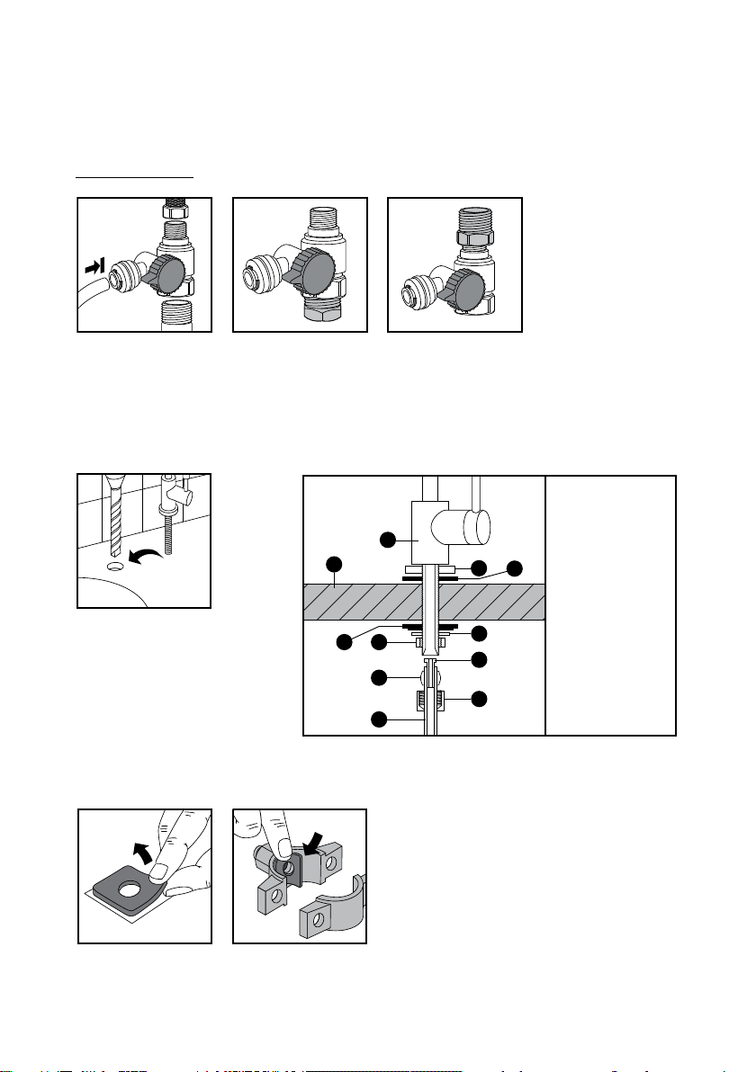
Installation Steps:
3/8”
1/2”
3/8”
3/8”
1/2”
1/2”
1. Install adapter ball valve (included) to the cold water supply. Use some Teon or plumbers
sealing tape to prevent leaks.
Use adapter valve without Conversion Adapter to have 1/2” and 3/8” conguration or Conversion Adapter can be threaded to either side of the valve to make congurations of 1/2” x 1/2”
or 3/8” x 3/8”.
1. Faucet
2. Chrome washer
3. Black rubber
4. Countertop or
3
5. Black washer
6. Lock washer
7. Lock nut
8. Insert
9. Sleeve
10. Compression
11. Tubing
washer
sink deck
nut
2. Create ½” hole for the ltered
water faucet and install it.
Tip: If you have a soap dispenser
or a water sprayer in an existing hole you may remove it and
1
4
5
7
9
11
2
6
8
10
use its hole for the ltered water
faucet.
3. Install drain saddle.
The square foam gasket with a circle cut out must be applied to the inside of the drain saddle. Remove sticky tape backing and stick to the drain saddle as shown.
10
Page 11
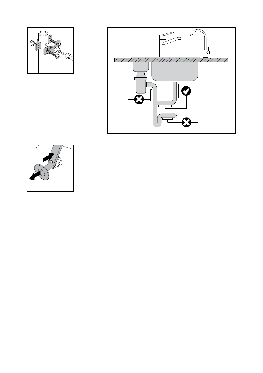
Drill a ¼” hole in the drain pipe
n d
l
n
■
Connect with the tubing the "to faucet" outlet of the R.O. filtration unit with the faucet.
above the trap and on the vertical or horizontal tail piece. Locate the drain connection away
from the garbage disposal to
prevent potential contamination
and system fouling.
never
mount
here
mount drain
saddle here
never mount
here
4. Remove gags and connect tubes as follows. See the connection chart for details.
■
Insert water supply tubing from inlet valve adapter into the “inlet” tting of the pump box unit.
■
Insert the supply tubing from the “RO unit” tting of the pump box unit into the supply inlet
of the R.O. ltration unit.
■
Insert the ltered water tubing from the permeate outlet of the R.O. ltration unit into the
“permeate” tting of the pump box unit.
■
Insert the waste tubing from the waste water outlet of the R.O. ltration unit into the
“waste” tting of the pump box unit.
■
Insert the waste tubing from the “drain” tting of the pump box unit into the drain saddle
(through the optional union check valve on the way) or to a waste water collection con-
tainer. Install the check valve with the arrow in the direction of ow.
11
Page 12
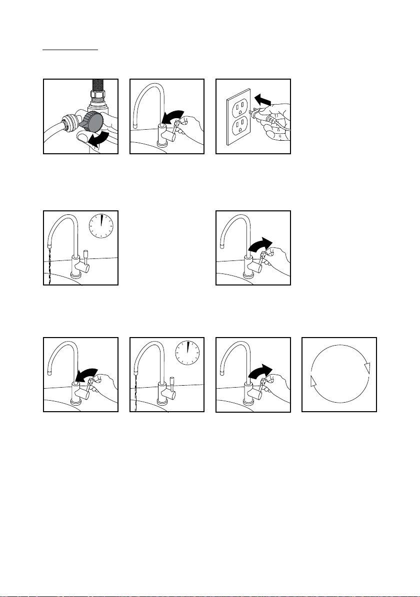
Initial Washing:
Aer installation it is recommended to perform the initial washing of the system. For this:
■
open cold water
supply valve;
■
open the inlet
valve;
■
open the ltered
water faucet;
■
plug the pump
box unit’s power
cord into the
electrical outlet;
2 min
■
wait for water to arrive at the faucet (it
may take a while, water foam and air may
be going out of the system);
■
wait for 2 minutes for more or less steady
water ow from the faucet and shut o
the faucet;
■
wait for auto ush to complete (18 s);
repeat
2 min
5-10
times
■
repeat the cycle “open the ltered water faucet – wait for 2 minutes – shut o the ltered
water faucet – wait for auto ush to complete” 5-10 times;
■
aer you nished with previous step shut o the faucet, and your system is ready for use.
Please note that aer initial installation or changing the lters or membrane, air contained
in the new dry system or lter may go out sometimes producing foamy, white ltered water.
Water may look white due to tiny air bubbles in it. If you leave the water to stand for few minutes all bubbles will surface and eliminate. Such aerated water is clean and safe. Gradually
over the coming days all air inside your system will nd its way out. To make this process
faster you may repeat the initial washing procedure until you’re pleased with the result. Also
note that if for some reason the water supply contains a lot of dispersed air, your R.O. system
may start producing aerated water again. The system’s internal pipes and components never
take air from outside as they are completely air and water sealed and leak-free.
12
Page 13

Regular Use
To get clean water just open the ltered water faucet. The pump will turn on automatically and will
produce the ltered water ow in real time until you shut o the faucet. At the end of each water
production cycle the membrane will be ushed, and then the system will shut o automatically.
Please note that R.O. membrane needs up to 50 hours of active operation before reaching
peak performance in terms of water ow, recovery and rejection rates.
For your safety and peace of mind please unplug the pump box unit from the electrical out-
let and shut o the inlet valve before servicing your R.O. system such as changing lters or
membrane, or during vacations.
Tips:
■
You may install the optional union tee tting to the tubing line prior to the ltered water
faucet to get another line of clean water going to the other point-of-use (such as a sink in
a bathroom or ice maker in your fridge).
■
Operating the system using soened feed water greatly reduces the chances of membrane
failure and prolongs lters and membrane service life.
Changing Filters and Membrane
This R.O. system contains the replaceable components critical to the eciency of the system.
Replacement of a component should be with one of identical specications, as dened by the
manufacturer, to assure the same eciency and contaminant reduction performance.
To reduce the risk of water leakage or ooding, and to ensure optimal R.O. system performance:
■
Change the disposable pre-lters every 6 months or sooner if you observe a noticeable
reduction in water ow rate.
■
Change the disposable post-lter every 12 months or sooner if you observe a noticeable
reduction in water ow rate.
■
Change the disposable R.O. membrane every 36 months or sooner if you observe a notice-
able reduction in water ow rate.
Failure to replace the disposable lters & membrane at recommended intervals may lead to reduced system performance and cracks in the lter housings, causing water leakage or ooding.
Please note the capacity of the lters and membrane is limited. Their service life depends on
the degree of contamination of the water supply and system usage. All terms apply to normal
household use. Actual performance may vary. You may need to change lters or the membrane sooner than indicated if you notice chlorine or other tastes or smells, etc. Manufacturer
recommends a TDS test every six months.
Replacement Filters:
■
K871 (sediment pre-lter)
■
K870 (activated carbon pre-lter)
■
K858 or K856 (high-production R.O.
membrane)
■
K880 (activated carbon post-lter and
conditioner)
Optional post-lters which can also be used
instead of K880:
■
K875 (granular activated carbon post-lter)
■
K873 (granular activated carbon with
schungite natural mineral post-lter)
■
K870 carbon block pre-lter may also be
used as a post-lter.
To prevent leakage or cracks and ensure the safety of operation and top performance do not
disassemble the lters or try to regenerate them.
13
Page 14
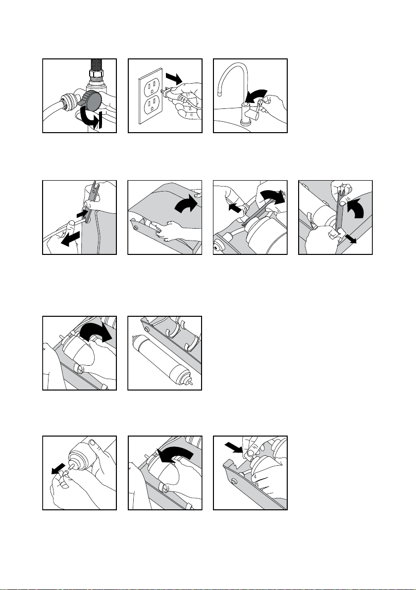
To change lter(s) or membrane:
■
shut o the inlet
valve
■
unplug the pump
box unit from the
■
relieve the water pressure by opening the
ltered water faucet
electrical outlet
■
remove the R.O. ltration unit from its
place for easier access (disconnect external tubes if necessary) and open the unit’s
■
locate the lter (membrane) to be
changed, disconnect its inlet and outlet
ttings and remove it
cover
Note: Remove and change back one lter at
a time, one aer another. Do not remove all
lters at once to avoid mixing up the tubes.
■
take new lter (membrane) and install it in the place of the removed one observing the
water ow direction arrow on its label and restoring the connections (see the internal con-
nections chart for details)
or
14
Page 15
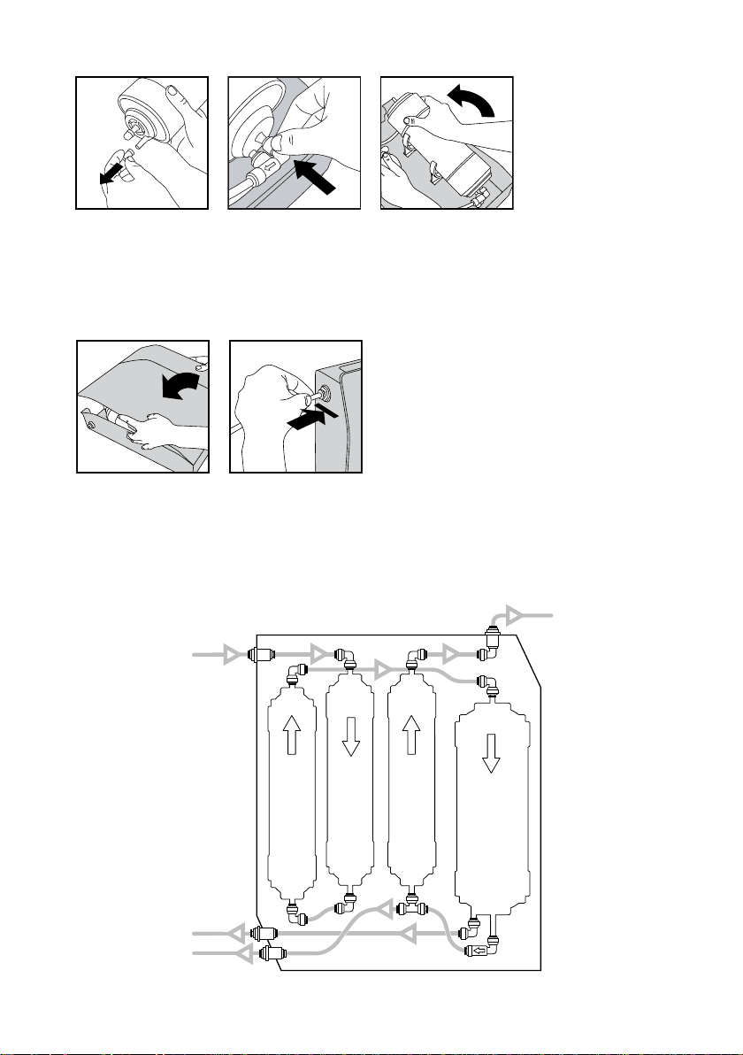
Note: For a pre- or post-lter you only need to connect its inlet and outlet. For the membrane
membrane K858
pre-filter K871
pre-filter K870
post-filter K880
waste water outlet
permeate outlet
R.O. unit inlet
to the faucet
R.O Filtartion Unit Internal Connections Chart
you have to connect the third outlet – to the waste water line. This outlet is located o the
center of the membrane housing. Elbow check valve tting (with the arrow) has to be con-
nected to the central (permeate) outlet of the membrane housing.
■
close the cover, reconnect the external tubes and place the unit back in its place
Aer you nished changing lters or the membrane follow the “initial washing” procedure as
described above. With initial operation, check for leaks. If a leak is observed, verify that the
tube or branch pipe of the lter/membrane housing is pushed into the quick tting far enough
to seal the tube against the O-ring and that the tubing was cut at 90o.
15
Page 16

Prio, Prio logo are the trademarks of DWT Deutsche Wassertechnologien GmbH, Germany.
As used herein, ® denotes registered trademark status in Germany only.
16
Copyright © DWT Deutsche Wassertechnologien GmbH, Germany, 2014, 2018
 Loading...