

Administrator’s Manual
T800
Thermal Printers

Printronix Auto ID makes no representations or warranties of any kind regarding this
not limited to, implied warranties of merchantability
shall not be held responsible for errors contained herein or any omissions from this material or for any
damages, whether direct, indirect, incidental or consequential, in connection with the furnishing,
distribution, performance or use of this material. The
without notice.
This document contains proprietary information protected by copyright. No
reproduced, copied, translated or incorporated
manual, graphic,
ID.
COPYRIGHT © 2018 PRINTRONIX AUTO ID TECHNOLOGY, INC. All rights reserved.
electronic, mechanical or otherwise, without the prior written consent of Printronix Auto
and fitness for a particular purpose. Printronix Auto ID
information in this manual is subject to change
part of this document may be
in any other material in any form or by any means, whether
material, including, but
Trademark Acknowledgements
Printronix, IGP, Auto Label Mapping, LinePrinter Plus, PGL, and PrintNet are registered trademarks of
Printronix, Inc.
T800, T8000, and T6000 are trademarks of Printronix Auto ID Technology, Inc.
Code V is a trademark of QMS, Inc.
QMS is a registered trademark of Quality Micro Systems, Inc.
IBM is registered trademark of International Business Machines Corp.
MS-DOS and Windows are registered trademarks of Microsoft Corporation.
EIA is a registered service mark of Electronic Industries Association.
ZPL, ZPL II, and Zebra are registered trademarks of Zebra Technologies Corporation.
TEC is a registered trademark of the Toshiba TEC Corporation.
Intermec is a registered trademark of the Intermec Technologies Corporation.
SATO is a registered trademark of SATO America, Inc.
DPL is a trademark and Datamax is a registered trademark of Datamax Technologies Corporation.
IER is a registered trademark of IER Siège
Monarch is a registered trademark of Paxar Corporation.
SD, SDHC and SDXC are trademarks or registered trademarks of SD-3C, LLC in the United States, other
countries or both. Also, miniSD, microSD, miniSDHC, microSDHC, microSDXC, smartSD, smartSDHC,
SDIO and miniSDIO are all trademarks or registered trademarks of SD-3C, LLC in the United States,
other countries or both.
Page | 2

Regulatory Compliance
EN 55032:2015
EN 55024
EN 60950-1
This is a class A product. In a domestic environment this product may cause radio
interference in which case the user may be required to take adequate measures.
FCC part 15B, Class A
ICES-003, Class A
This equipment has been tested and found to comply with the limits for a Class A
digital device, pursuant to Part 15 of the FCC Rules. These limits are designed to
provide reasonable protection against harmful interference when the equipment is
operated in a commercial environment.
Operation is subject to the following two conditions: (1) This device may cause
harmful interference, and (2) this device must accept any interference received,
including interference that may cause undesired operation.
This equipment generates, uses, and can radiate radio frequency energy and, if not
installed and used in accordance with the manufacturer’s instruction manual, may
cause harmful interference with radio communications. Operation of this equipment
in a residential area is likely to cause harmful interference, in which case you will be
required to correct the interference at your own expense.
This Class A digital apparatus complies with Canadian ICES-003.
Cet appareil numérique de la classe A est conform à la norme NMB-003 du Canada.
AS/NZS CISPR 32, Class A
K 60950-1, KN 32 / KN 35
이 기기는 업무용(A 급) 전자파적합기기로서 판매자 또는 사용자는 이 점을
주의하시기 바라며, 가정외의 지역에서 사용하는 것을 목적으로 합니다.
GB 4943.1
GB/T9254, Class A
GB 17625.1
此为 A 级产品,在生活环境中,该产品可能会造成无线电干扰,
在这种情况下,可能需要用户对干扰采取切实可行的措施。
Energy Star for Imaging Equipment Version 2.0
The menu setting System > Energy Star > Pwr Saver Time is default 5 minutes and
can be modified by user if desired.
IS 13252(Part 1)/
IEC 60950-1
Page | 3
UL 60950-1
CAN/CSA-C22.2 No. 62368-1
NOM-019
CNS 13438
CNS 14336-1
CNS 15663
TP TC 004
TP TC 020
Important safety instructions:
1. Read all of these instructions and keep them for later use.
2. Follow all warnings and instructions on the product.
3. Disconnect the power plug from the AC outlet before cleaning or if fault happened.
Do not use liquid or aerosol cleaners. Using a damp cloth is suitable for cleaning.
4. The mains socket shall be installed near the equipment and easily accessible.
5. The unit must be protected against moisture.
6. Ensure the stability when installing the device, Tipping or dropping could cause damage.
7. Make sure to follow the correct power rating and power type indicated on marking label provided by
manufacture.
8. Please refer to user manual for maximum operation ambient temperature.
WARNING:
Hazardous moving parts, keep fingers and other body parts away.
CAUTION:
(For equipment with RTC (CR2032) battery or rechargeable battery pack)
Risk of explosion if battery is replaced by an incorrect type.
Dispose of used batteries according to the Instructions as below.
1. DO NOT throw the battery in fire.
2. DO NOT short circuit the contacts.
3. DO NOT disassemble the battery.
4. DO NOT throw the battery in municipal waste.
5. The symbol of the crossed out wheeled bin indicates that the battery should not be placed in municipal
waste.
Caution: The printhead may be hot and could cause severe burns. Allow the printhead to cool.
CAUTION:
Any changes or modifications not expressly approved by the grantee of this device could void the user's
authority to operate the equipment.
Page | 4

Frequency Band
Country
Remark
5150-5350MHz
Azerbaijan
No license needed if used
indoor and power not
exceeding 30mW
5470-5725MHz
Below statement are for product with optional RF function.
CE Statement:
This equipment complies with EU radiation exposure limits set forth for an uncontrolled environment. This
equipment should be installed and operated with minimum distance 20 cm between the radiator & your
body.
All operational modes:
2.4GHz: 802.11b, 802.11g, 802.11n (HT20), 802.11n (HT40)
5GHz: 802.11a, 802.11ac.
The frequency, mode and the maximum transmitted power in EU are listed below:
2400 MHz – 2483.5 MHz: 19.88 dBm (EIRP)(Wi-Fi)
5150 MHz – 5250 MHz: 17.51 dBm (EIRP)(Wi-Fi)
2402 MHz – 2480 MHz: 6.02 dBm (EIRP)(Bluetooth)
Requirements in
AT/BE/BG/CZ/DK/EE/FR/DE/IS/IE/IT/EL/ES/CY/LV/LI/LT/LU/HU/MT/NL/NO/PL/PT/RO/SI/SK/TR/FI/SE/C
H/UK/HR. 5150MHz~5350MHz is for indoor use only.
5150-5350MHz for Only indoor use
5470-5725MHz for indoor/outdoor use
Restrictions In AZE
National restrictions information is provided below
Hereby, PRINTRONIX Auto ID Technology Co., Ltd. declares that the radio equipment type [Wi-Fi] IEEE
802.11 a/b/g/n/ac is in compliance with Directive 2014/53/EU
The full text of the EU declaration of conformity is available at the following internet address:
http://printronixautoid.com/declarations-of-conformity/
Canada, Industry Canada (IC) Notices
This Class A digital apparatus complies with Canadian ICES-003 and RSS-210.
Operation is subject to the following two conditions: (1) this device may not cause interference, and (2) this
device must accept any interference, including interference that may cause undesired operation of the
device.
Canada, avis de l'Industry Canada (IC)
Cet appareil numérique de classe B est conforme aux normes canadiennes ICES-003 et RSS-210.
Son fonctionnement est soumis aux deux conditions suivantes : (1) cet appareil ne doit pas causer
d'interférence et (2) cet appareil doit accepter toute interférence, notamment les interférences qui peuvent
affecter son fonctionnement.
NCC
警語:
經型式認證合格之低功率射頻電機,非經許可,公司、商號或使用者均不得擅自變更頻率、加大功率或變更
原設計之特性及功能。(即低功率電波輻射性電機管理辦法第十二條)
低功率射頻電機之使用不得影響飛航安全及干擾合法通信;經發現有干擾現象時,應立即停用,並改善至無
干擾時方得繼續使用。
Page | 5
前項合法通信,指依電信法規定作業之無線電通信。低功率射頻電機須忍受合法通信或工業、科學及醫療用
單元 Unit
限用物質及其化學符號
Restricted substances and its chemical symbols
鉛Lead
(Pb)
汞Mercury
(Hg)
鎘
Cadmium
(Cd)
六價鉻
Hexavalent
chromium
(Cr+6)
多溴聯苯
Polybrominated
biphenyls
(PBB)
多溴二苯醚
Polybrominated
diphenyl ethers
(PBDE)
內外塑膠件
○ ○ ○ ○ ○
○
內外鐵件
○ ○ ○ ○ ○
○
滾輪
○ ○ ○ ○ ○
○
電路板組件
- ○ ○ ○ ○
○
晶片電阻
- ○ ○ ○ ○
○
積層陶瓷表
面黏著電容
○ ○ ○ ○ ○
○
集成電路-IC
○ ○ ○ ○ ○
○
電源供應器
○ ○ ○ ○ ○
○
印字頭
○ ○ ○ ○ ○
○
馬達
- ○ ○ ○ ○
○
插座
○ ○ ○ ○ ○
○
線材
○ ○ ○ ○ ○
○
備考 1.〝超出 0.1 wt %〞及〝超出 0.01 wt %〞係指限用物質之百分比含量超出百分比含量基準值。
Note 1:“Exceeding 0.1 wt %” and “exceeding 0.01 wt %” indicate that the percentage content of the restricted substance exceeds the reference
percentage value of presence condition.
備考 2.〝○〞係指該項限用物質之百分比含量未超出百分比含量基準值。
Note 2:“○” indicates that the percentage content of the restricted substance does not exceed the percentage of reference value of presence.
備考 3.〝-〞係指該項限用物質為排除項目。
Note 3:The “−” indicates that the restricted substance corresponds to the exemption.
電波輻射性電機設備之干擾。(即低功率電波輻射性電機管理辦法第十四條)
BSMI Class A
這是甲類的資訊產品,在居住的環境使用中時,可能會造成射頻 干擾,在這種情況下,使用者會被要求採
取某些適當的對策。
限用物質含有情況標示聲明
警語:
Page | 6

Warnings and Special Information
For your safety and to protect valuable equipment, read and comply with all information highlighted under
special headings:
WARNING Conditions that could harm you and damage the equipment.
WARNING Achten Sie auf folgendes, um keine Personen in Gefahr zubringen bzw. das
Gerät zu beschädigen.
WARNING Condiciones que pueden causar daños a personas y equipos.
WARNING Conditions à respecter pour éviter tout danger corporel et dommage matériel.
WARNING Condizioni che possono arrecare danni alle persone e alle apparecchiature.
CAUTION
Conditions that could damage the printer or related equipment.
IMPORTANT Information vital to proper operation of the printer.
NOTE: Information and helpful tips about printer operation.
Important Safety Instructions
1. Read all of these instructions and keep them for later use.
2. Follow all warnings and instructions on the product.
3. Disconnect the power plug from the AC outlet before cleaning or if a fault occurs.
4. Do not use liquid or aerosol cleaners. Using a damp cloth is suitable for cleaning printer surfaces.
5. The mains socket shall be installed near the equipment and easily accessible.
6. The unit must be protected against moisture.
7. Ensure the stability when installing the device. Tipping or dropping could cause damage.
8. Make sure to follow the correct power rating and power type indicated on marking label provided by
manufacturer.
9. Please refer to user manual for maximum operation ambient temperature.
WARNING Hazardous moving parts, keep fingers and other body parts away.
CAUTION Risk of explosion if RTC battery is replaced by an incorrect type. Dispose of used
batteries according to the Instructions listed below.
6. DO NOT throw the battery in fire.
7. DO NOT short circuit the contacts.
8. DO NOT disassemble the battery.
9. DO NOT throw the battery in municipal waste.
10. The symbol of the crossed out wheeled bin indicates that the battery should not be
placed in municipal waste.
CAUTION The printhead may be hot and could cause severe burns. Allow the printhead to
cool before servicing.
Page | 7

Manual Conventions
• Operator panel keys are printed in uppercase letters.
Example: Press the PAUSE key and then press ENTER.
• Operator panel keys are often shown by their symbol or icon (located on the control panel directly
above the key).
Example: Press the key for ENTER.
• Operator panel menu settings are often shown by their full location that includes the ICON name,
submenu, and then menu, each separated with a ‘>’ sign.
Example: Change the Media > Image > Label Length menu.
• Control panel LCD messages are printed in uppercase letters inside quotation marks ( “ ” ).
Example: When “OFFLINE” appears on the control panel LCD, you may release the PAUSE key.
• Key combinations are indicated by the + (plus) symbol.
Example: Press + means Press the Up key and the Down key at the same time.
Page | 8

Table of Contents
Trademark Acknowledgements ........................................................................... 2
Regulatory Compliance ....................................................................................... 3
Warnings and Special Information ...................................................................... 7
Important Safety Instructions ............................................................................... 7
Manual Conventions ............................................................................................ 8
1 Introduction .................................................................. 17
The T800 Family of Printers .............................................................................. 17
Standard Features ............................................................................................. 17
Optional Features .............................................................................................. 18
2 Operation ..................................................................... 19
Controls and Indicators...................................................................................... 19
Power Switch .............................................................................................. 19
Control Panel .............................................................................................. 19
Operating Modes ............................................................................................... 20
Online Screen .................................................................................................... 21
Offline (Home) Screen ....................................................................................... 22
Wizard .............................................................................................. 22
Settings .............................................................................................. 23
Calibrate .............................................................................................. 25
Fault ..................................................................................................... 25
Job in Process ............................................................................................ 25
Media Handling Modes ...................................................................................... 26
Setting Up the Printer ........................................................................................ 26
Loading Ribbon ........................................................................................... 28
Loading Media ............................................................................................ 30
Loading External Media .............................................................................. 33
Positioning the Media Sensors ................................................................... 34
Sensing Different Media Types ................................................................... 36
Media with No Label Length Indicators ........................................................ 37
Media with Underside Horizontal Black Marks ............................................... 37
Media with Gaps, Notches or Holes ........................................................... 37
Media with Gaps ......................................................................................... 37
Calibrating the Media Sensors .................................................................... 37
Running Auto Calibrate ............................................................................... 38
Running Media Profile ................................................................................. 39
Gap Sensing ............................................................................................... 40
Page | 9

Running Manual Calibrate .......................................................................... 40
Label Peel-Off (Optional) ................................................................................... 42
Loading Media Using Peel-Off Mode .......................................................... 42
Configuring the Printer Menu ...................................................................... 43
Media Cutter (Optional) ..................................................................................... 44
Loading Media Using Cutter Mode ............................................................. 44
Configuring the Printer Menu ...................................................................... 44
Printing Adjustments .......................................................................................... 45
Printhead Burn Line Adjustment ................................................................. 45
Cleaning ............................................................................................................ 46
Exterior Cleaning ........................................................................................ 46
Interior Cleaning .......................................................................................... 46
Cleaning the Printhead, Platen Roller, Media Sensors/Damper ................. 46
Printhead Cleaning ..................................................................................... 46
Platen Roller Cleaning ................................................................................ 47
Media Sensor Cleaning ............................................................................... 47
Cutter Option Cleaning ............................................................................... 48
3 Printer Settings ............................................................ 49
Overview ............................................................................................................ 49
Setting Printer Configuration Parameters .................................................... 49
Saving a Configuration
Auto Save Configuration ............................................................................. 52
Naming Configurations ............................................................................... 52
Loading a Configuration .............................................................................. 53
Specifying a Power-Up Configuration ......................................................... 54
Modifying a Saved Configuration ................................................................ 54
Viewing the Current Configuration .............................................................. 54
Printing a Configuration .............................................................................. 54
Settings Organization
Quick Setup ........................................................................................ 56
Menu Items ................................................................................................. 56
Entering Safe Mode .................................................................................... 57
Exiting Safe Mode ....................................................................................... 57
Forgot the Password ................................................................................... 58
Media
Intro: Label Length ...................................................................................... 59
Intro: Clip Page ........................................................................................... 59
.................................................................................................... 59
.................................................................... 51
........................................................................ 55
Page | 10
Media > Image ............................................................................................ 60
Media > Speed ............................................................................................ 66
Media > Handling ........................................................................................ 67
Media > Ribbon ........................................................................................... 72
Media > TOF ............................................................................................... 72
Media > Fault .............................................................................................. 74
Media > Auto Label Map ............................................................................. 75
Auto Label Map Examples .......................................................................... 76
Example 1: Simple Case ............................................................................. 76
Example 2: Uneven Number Case .............................................................. 77
Example 3: Past Maximum File Width ......................................................... 78
Example 4: Blank Label Case ..................................................................... 78
Sensors ................................................................................................ 79
Intro: Sensor Types ..................................................................................... 79
Sensors > Control ....................................................................................... 79
Sensors > Calibrate .................................................................................... 81
Sensors > Diagnostics ................................................................................ 87
System
Host IO
Network ............................................................................................ 113
System > Control ........................................................................................ 88
System > Energy Star ................................................................................. 91
System > Flash File View ........................................................................... 91
System > Flash File Edit ............................................................................. 91
System > SD File View ............................................................................... 93
System > SD File Edit ................................................................................. 93
System > USB File View ............................................................................. 95
System > USB File Edit............................................................................... 95
System > Printer Mgmt ............................................................................... 96
System > Date ............................................................................................ 99
Host IO > Control ...................................................................................... 101
Host IO > USB Port ................................................................................... 101
Host IO > Serial Port ................................................................................. 103
Network > Control ..................................................................................... 113
Network > Ethernet ................................................................................... 115
Network > WLAN ...................................................................................... 118
Network > WLAN Params ......................................................................... 120
............................................................................................... 88
.......................................................................................... 101
Page | 11

Network > WLAN EAP .............................................................................. 127
Application
LP+, PGL, VGL Character Sets ................................................................ 129
Application > Control ................................................................................. 133
Application > PGL Setup ........................................................................... 138
Application > LP+ SETUP ......................................................................... 149
Application > P-SERIES Setup ................................................................. 154
Application > P-SERIES XQ Setup ........................................................... 160
Application > Serial Matrix Setup .............................................................. 164
Application > Proprinter Setup .................................................................. 168
Application > Epson FX Setup .................................................................. 171
Application > Fonts ................................................................................... 176
Configs .............................................................................................. 178
Configs > Control ...................................................................................... 178
Configs > Custom ..................................................................................... 179
Tools
Tools > Print Tests .................................................................................... 181
Tools > Diagnostics................................................................................... 182
Tools > Statistics ....................................................................................... 183
Tools > About ............................................................................................ 184
................................................................................................. 181
..................................................................................... 129
Page | 12
RFID .................................................................................................. 186
4 Downloading Firmware .............................................. 187
Firmware File Types (.prg) and (.exe) ............................................................. 188
Web Page Download ....................................................................................... 189
Windows Driver Download .............................................................................. 191
Automatic Download (.exe) ............................................................................. 192
Manual Two-Key Download Sequence ........................................................... 193
Manual Three-Key Download Sequence......................................................... 194
Sending Firmware in Download Mode ............................................................ 194
Sending Firmware via Ethernet (LPR) ...................................................... 195
Sending Firmware via USB ....................................................................... 195
Sending Firmware via Serial ..................................................................... 196
Downloading Files to the Main File System .................................................... 197
Filename Extensions Not Shown in Menus ..................................................... 197
File Properties Not Shown in Menus ............................................................... 198
Web Page Download ....................................................................................... 198

PTX_SETUP Download................................................................................... 200
Manual Two-Key Download ............................................................................ 200
Downloading Files to the SD Card .................................................................. 201
Using TrueType Fonts ..................................................................................... 201
Downloading TrueType Fonts ................................................................... 201
PGL Emulation .......................................................................................... 201
Adding a Header/Manual Two-Key Download .......................................... 202
Header for SD Card ................................................................................... 203
Labeling Applications ................................................................................ 203
Select and Print Downloaded TrueType Fonts ......................................... 203
To Print ASCII Characters ........................................................................ 203
To Print All Characters .............................................................................. 203
Demo Facility ................................................................................................... 203
Downloading a Demo File ......................................................................... 203
Configuring the Printer to Run a Demo File .................................................... 204
Starting a Demo File ................................................................................. 204
Pausing a Demo File ................................................................................. 204
Stopping a Demo File ............................................................................... 204
Deleting a Demo File ................................................................................ 204
WLAN Radio Firmware Upgrade ..................................................................... 205
Firmware Download Methods ................................................................... 205
Firmware File Types (.fls) and (.exe) ........................................................ 205
Web Page Download ................................................................................ 206
Windows Driver Download ........................................................................ 207
Automatic Download (.exe) ....................................................................... 207
Manual Two-Key Download Sequence ..................................................... 207
Page | 13
5 Diagnostics and Troubleshooting ............................... 208
Printer Tests ...................................................................................................... 208
Troubleshooting Common Situations ................................................................. 208
Interfacing ................................................................................................. 208
Hex Dump Mode ....................................................................................... 208
Controlling Print Quality ............................................................................ 209
Replacing the Printhead assembly ........................................................... 211
Restore the Printer to Operation ............................................................... 213
Diagnostics for Fatal Error ........................................................................ 213
Solving Other Printer Problems ................................................................ 214
Printer Alarms ........................................................................................... 222
Fault Messages ......................................................................................... 222
Operator-Correctable Fault Messages ..................................................... 222
Fault Messages Requiring Field Service Attention ................................... 222
Fatal Messages Requiring Firmware Upgrade or Diagnostics ................. 222
A Specifications ............................................................ 232

Print Method .............................................................................................. 232
Media ........................................................................................................ 233
Ribbon ....................................................................................................... 235
Indicators and Switches ............................................................................ 235
Memory ..................................................................................................... 236
Media Cutter Option .................................................................................. 236
Host Interfaces .......................................................................................... 237
Power ........................................................................................................ 237
Environmental ........................................................................................... 238
Physical ..................................................................................................... 238
Acoustic Specifications ............................................................................. 238
B Printer Options ........................................................... 239
Media Handling Accessories ........................................................................... 239
Media Cutter.............................................................................................. 239
Peel Dispenser .......................................................................................... 239
Hardware Options ............................................................................................ 239
RFID .......................................................................................................... 239
Interface Options ............................................................................................. 239
Wireless NIC (802.11 a/b/g/n/ac/b/g/n wireless) ....................................... 239
Bluetooth 4.2 ............................................................................................. 239
Software Options ............................................................................................. 240
Premium Asian Fonts ................................................................................ 240
Quick Change Memory Cartridge ............................................................. 240
Supplies ........................................................................................................... 240
Manuals ........................................................................................................... 240
Page | 14
C Media Cutter Installation
Preparing the Printer ....................................................................................... 241
Installing the Media Cutter ............................................................................... 241
D Peel-off Module Installation
Preparing the Printer ....................................................................................... 244
Installing the Peel-off Module .......................................................................... 244
................................................ 241
............................................ 244
E Loading WLAN Certificates ........................................ 247
Overview .......................................................................................................... 247
Loading Wifi Certificate file(s) from Windows .................................................. 247
Loading Wifi Certificate file(s) from Linux ........................................................ 247
Loading Wifi Certificate file(s) from Webpage ................................................. 248
F PTX_SETUP Commands ........................................... 250
Overview .......................................................................................................... 250
The PTX_SETUP Commands ........................................................................... 250

General Commands .................................................................................. 250
Summary of the CONFIG Command ........................................................ 255
Operation of the FILE_IO Command ........................................................ 255
Thermal Commands ................................................................................. 255
G Quick Change Memory Card (QCMC) ....................... 258
Overview .......................................................................................................... 258
Installing the QCMC ........................................................................................ 259
Saving the Printer’s Configuration to the QCMC ............................................. 259
Copying the QCMC “Snapshot” Image to a Second Printer
Updating the QCMC Image
Erasing the QCMC Image
................................................................................... 263
...................................................................................... 263
........................................... 261
H Custom Configuration Module (CCM) ........................ 265
Overview .......................................................................................................... 265
Creating a CCM ............................................................................................... 265
Using CCM To Configure A Printer ................................................................. 266
I Customer Support ...................................................... 268
Printronix Customer Support Center ............................................................... 268
Corporate Offices ............................................................................................ 269
J Glossary .................................................................... 270
K Communication Notices and Warranties .................... 275
Communication
European Union Conformity...................................................................... 277
Industry Canada Compliance Statement .................................................. 277
Statement of CISPR 32 Compliance ........................................................ 277
German Conformity Statement ................................................................. 278
Korea ......................................................................................................... 278
China ......................................................................................................... 279
Software License Agreement .......................................................................... 280
eCos .......................................................................................................... 281
Open SSL.................................................................................................. 282
OpenSSL License ..................................................................................... 282
Original SSLeay License ........................................................................... 283
WPA Supplicant License ........................................................................... 284
Brian Gladman AES Library ...................................................................... 284
Google Font Open Sans ........................................................................... 285
Cousine Font ............................................................................................. 285
Limited Software Product Warranty ................................................................. 286
Remedy ..................................................................................................... 286
Disclaimer of Warranties and Limitation of Remedies .............................. 286
Statements
................................................................................ 276
Page | 15

Termination of License Agreement ........................................................... 286
U.S. Government Restricted Rights .......................................................... 286
Acknowledgement of Terms and Conditions ............................................ 287
Warranty Information ....................................................................................... 288
PRINTER WARRANTY ............................................................................. 288
THERMAL PRINTHEAD ........................................................................... 288
SUPPLIES................................................................................................. 288
ON-SITE MAINTENANCE SERVICE ....................................................... 288
Page | 16
Version
Max Print
Speed (ips)
Printing
Density
Max Print
Width
T820
8
203
4.1
T830
6
300
4.1
1 Introduction
The T800 Family of Printers
NOTE: The terms “T800” and “printer” refer to both the T820 (203 DPI) and T830 (300 DPI) models.
The T800 series consists of a family of high quality, desktop direct thermal and thermal transfer printers
specifically designed for printing labels and tags from multiple environments:
• Windows
• Unix/Linux
• MS-DOS
• SAP/ERP (PGL-based SAP device type)
The T800 series is comprised of the products detailed in Table 1.
®
®
Table 1. The T800 Series
Standard Features
• Thermal Transfer and Direct Thermal Printing
• High Resolution Printhead: 203dpi or 300dpi for sharp graphics and text.
• Sensors: Fixed media Gap, adjustable Black Mark sensor, Head Open, Ribbon End sensors
• User Interface: 3.5” color LCD screen, with 9 button keyboard
• 128MB DDR3 memory (fixed).
• 128MB NAND Flash memory (fixed).
• Auto Label Mapping®: For compatibility with programs written for Printronix line matrix printers.
• Bar Codes: Supports multiple types of 1-D and 2-D bar codes.
• Download: Fonts, forms, and graphics to printer memory.
• Emulations:
o Printronix PGL® for text, barcodes, graphics, lines, and boxes.
o Printronix LinePrinter Plus® (LP+) for direct compatibility with Printronix P-Series printers,
Epson FX-1050, Proprinter IIIXL, and Serial Matrix Printers.
o Printronix VGL. Emulates the QMS Code V™ Version II programming language.
17

o ZGL interpreter for legacy ZPL (Zebra®) applications
o TGL interpreter for legacy TEC (TEC®) applications
o IGL interpreter for legacy IPL (Intermec®) applications
o STGL interpreter for legacy SPL (SATO®) applications
o DGL interpreter for legacy DPL™ (Datamax®) applications
o IEGL interpreter for legacy IER-520® (IER®) applications
o MGL interpreter for legacy MPCL II® (Monarch®) applications
o EGL interpreter for Eltron® applications
• Serial RS-232: DB9 connector
• USB 2.0 Universal Serial Bus
• Network Interface Port: This interface allows you to attach the printer to a LAN (Local Area
Network). The port is visible on the back panel. The Ethernet port is a 10/100Base and supports
data transfer rates up to 100 Mbps. The PrintNet Enterprise Suite (PNE) remote management
software can be downloaded from
• Real Time Clock (RTC): The RTC has an internal battery. The clock keeps track of the year,
month, day, hour, minute and second values. It will continue to operate when the printer is off.
Graphic languages can use the RTC values to program fields in labels to indicate the date and/or
time.
http://www.printronixautoid.com.
• Resident Fonts (Standard Firmware): Letter Gothic Bold (#93779), Courier Bold (#93952), CG
Triumvirate Bold Condensed (#92250), OCR-A (#90993), OCR-B (#91409), CG Triumvirate
(#92244), CG Triumvirate Bold (#92248), and CG Times New Roman (#92500).
• Mini SD memory card slot: Supports SD cards from 4 to 32 GB.
Optional Features
Ask your authorized representative about the following enhancement options:
• Peel Dispenser: Peels off labels one at a time before printing the next label. Liner is ejected to
front of printer.
• Media Cutter: Automatically cuts printed media when the media exits the printer.
• RFID MP2 Encoder: The RFID (Radio Frequency Identification) UHF encoder reads and writes
information to smart labels (with embedded RFID tags) with a pitch typically two to six inches.
These labels are used on shipping cartons and pallets. Not available as a field installed option
(factory only).
• Premium Asian Fonts: A selection of three different purchasable Asian fonts can be provided
(one font per SD card). These Asian fonts include Hanzi GB, Kanji SJIS, and Hangul. They are
available for use when the SD card is installed.
• QCMC (Quick Change Memory Card): The QCMC SD card provides the ability to duplicate an
entire printer’s firmware, saved configurations, and custom files quickly through the printer’s
control panel with a user friendly interface.
• Bluetooth 4.2: The BT 4.2 adapter provides wireless communications protocol designed for low
power usage, within a short range. Not available as a field installed option (factory only).
• Wireless Network: This card provides wireless 802.11a/b/g/n/ac/b/g/n connectivity without
expensive cabling and reconfigurations required from a wired network. Wi-Fi Alliance certified.
PNE is standard with this option. Not available as a field installed option (factory only).
For more information about printer options, see Appendix B page 239.
18
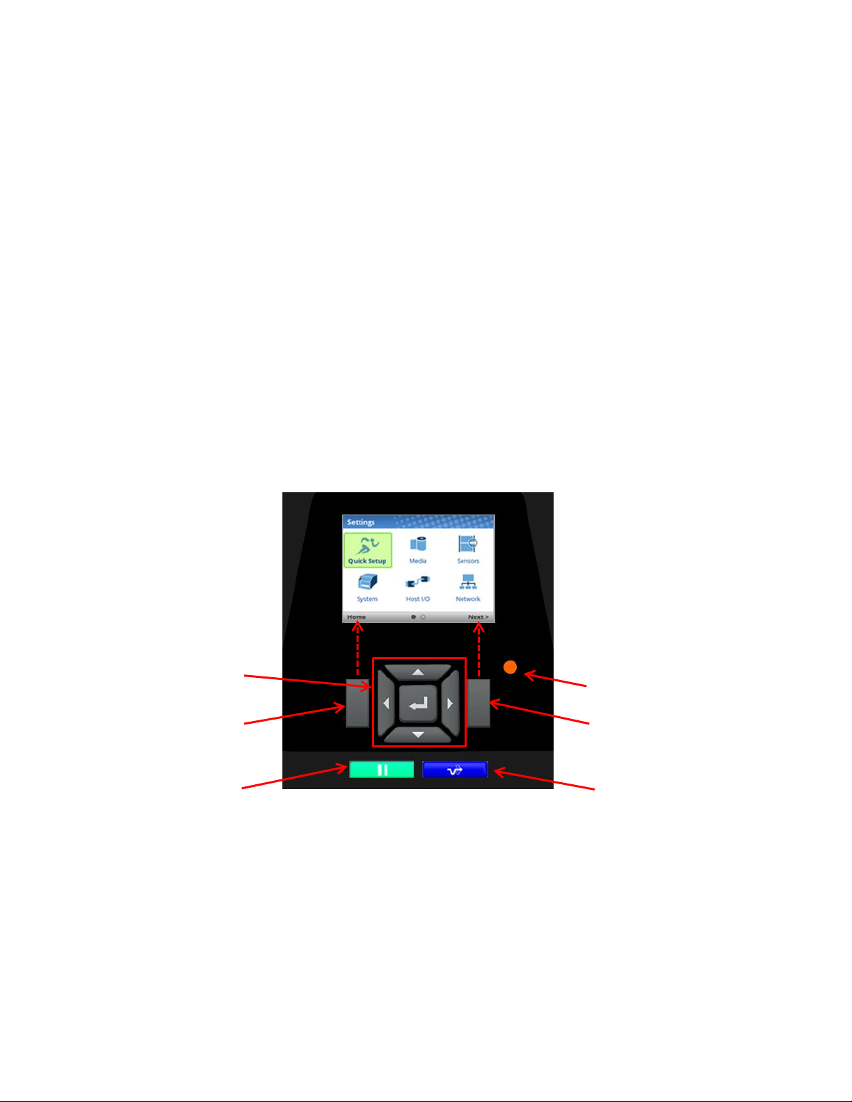
Navigation / Enter
Status LED
RIGHT SOFT key
FEED Key
LEFT SOFT key
PAUSET key
2 Operation
Controls and Indicators
Power Switch
The power switch is located on the bottom back left panel of the printer. To apply
the | (ON) position. When you first power on the
on the color LCD control panel.
To remove power, place the power switch in the O (OFF) position.
printer, an initialization sequence will immediately appear
Control Panel
The control panel is located on the top of the printer and includes a Status LED, QVGA color display,
PAUSE key, FEED key, LEFT SOFT key, RIGHT SOFT key, and navigation keys (buttons) with the
ENTER button in the center. These are described in the following
tables.
power, place the switch in
The QVGA (quarter VGA) screen is a 320 x 240 pixel color display (non-touch). It is comprised of a Header
that shows the printer state and location with the User Interface (UI), the general display area, and a footer
used to show the purpose of the LEFT and RIGHT SOFT keys (when available).
The status LED indicates when the
• LED is on solid: ONLINE and Ready to Print.
• LED is off: OFFLINE and not accepting data.
• LED is flashing: Fault Indicator.
printer is ONLINE, OFFLINE, or when there is a fault condition:
19
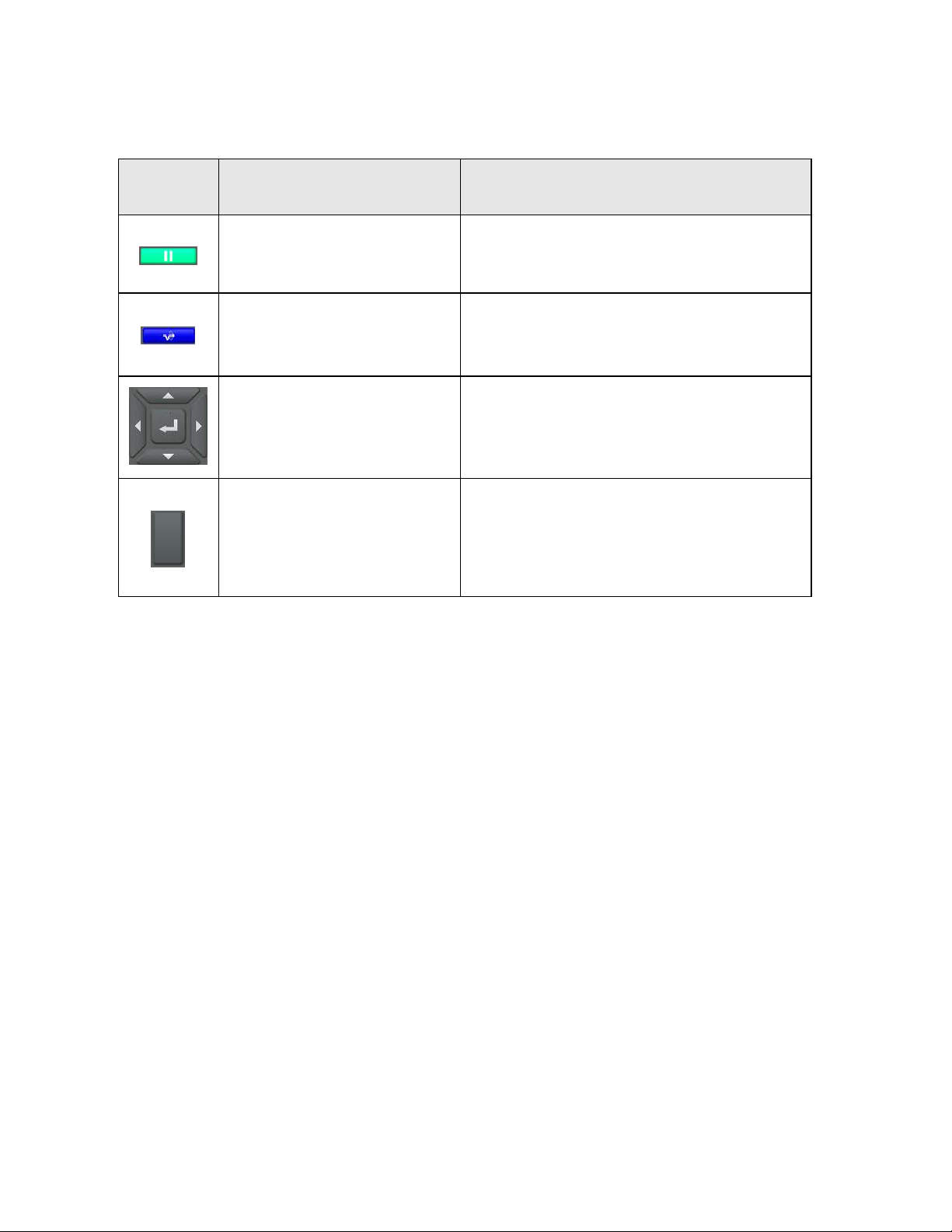
Button
Description
Functionality
PAUSE Key
Toggles the printer between
ONLINE and OFFLINE Modes.
When ONLINE, sets printer to OFFLINE Mode
and the UI to the Home Screen.
When OFFLINE, puts the printer back ONLINE.
FEED Key
Advances the media one label length. When
ONLINE, the menu System Control > Feed Key
Online must be enabled for this key to function.
Navigational Keys
The navigational menus consist
of up, down, left, and right keys
with a
ENTER button in the
center for selection.
Used to select icons, menu selection, and
navigation in the UI.
Soft Keys
There is a LEFT and RIGHT
SOFT key on the sides of the
navigational menus. The labels
on the footer of the UI will
explain their function.
Check the labels on the footer of the UI screen.
The meaning of the soft keys will vary.
NOTE: The printer is shipped with the ENTER button locked. To unlock, press the UP+DOWN arrow keys
simultaneously until you see the message “ENTER SWITCH UNLOCKED”.
Operating Modes
The operating mode can be selected through the control panel keys or can result from routine operations
such as powering on the printer.
Online: In ONLINE mode, the printer can receive and print data sent from the
key toggles the printer between the ONLINE and
Offline (Home): When the printer goes OFFLINE, the Status LED is off and the UI is in Home Screen. From the
Home Screen, the user has three different icons to choose from: 1) Wizard, 2) Settings, and 3) Calibrate. The
green highlighted icon is the current selection. Pressing the PAUSE key toggles the printer from
Screen to ONLINE mode.
Settings: When Settings is chosen from the Home Screen, the user has access to the printer menus by
navigating icons and traversing menu lists. Configurations can be saved using the Configs icon or by use of
the Auto-Save feature when returning ONLINE.
Wizard: When Wizard is chosen from the Home Screen, the user can perform different areas of printer setup
with the help of detailed explanations, references to online videos, and other material. On the first power-cycle,
the user will automatically be taken into the Printer Setup Wizard.
Fault: In fault mode, a fault condition exists that must be cleared before
LED indicator flashes, and the UI shows the Fault screen.
Before normal printing can continue, the fault must be corrected, the message cleared by pressing the
PAUSE key, and the printer placed ONLINE.
OFFLINE modes. The Status LED indicator is on.
host. Pressing the PAUSE
Home
printing can continue. The Status
20
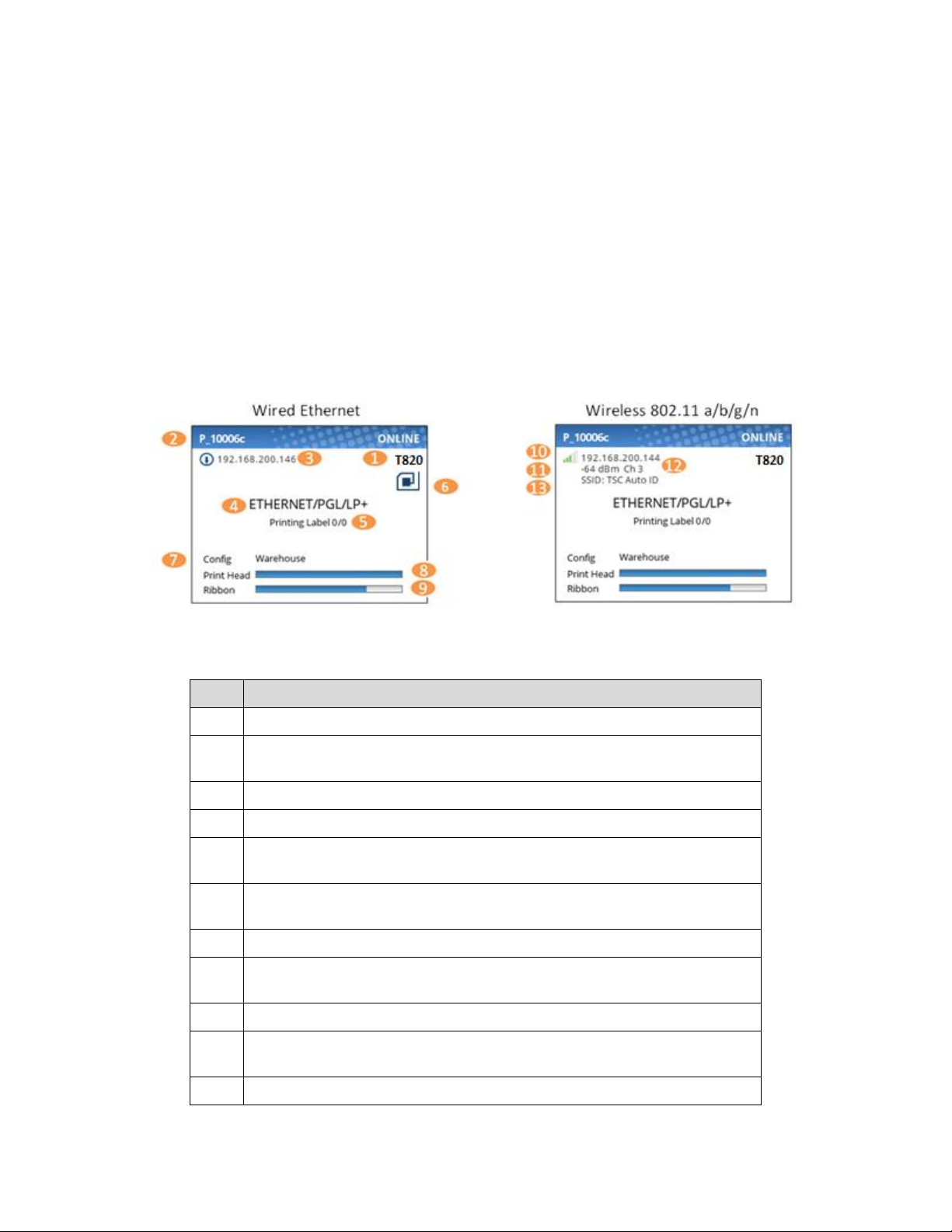
Item
Description
1
The full model name includes the printer width and DPI.
2
The Network Printer Name can be set via telnet, SNMP, or the webpage
and is used with Ethernet or WLAN features.
3
The Ethernet IP address is displayed if the IP address is set (non-zero).
4
The active IGP Emulation and the active Host IO (based on last job).
5
This area is reserved for messages such as receiving data, batch
counters, and job status.
6
The RFID icon will show when the RFID option is installed and active. If
installed but not active it will be shown as grey and disabled.
7
The last loaded configuration is referred to as the “Active Config”.
8
The print head gauge is used to show how much of the print head has
been used in relationship to the warranty.
9
The ribbon gauge is used when a ribbon is installed (thermal transfer).
10
The WLAN IP address is displayed if the IP address is set (non-zero).
There is also a signal strength indicator next to the WLAN address.
11
The WLAN signal strength is displayed in dBm
Online Screen
When the printer is ONLINE and ready to receive data, the ONLINE screen is shown. By default, this will
be the first screen the user sees after the power-up process has completed. In order to demonstrate the
full features of the ONLINE Screen, the following options are assumed:
• Model T820 (203 DPI)
• Network is installed and IP is set
• Wi-Fi is installed and IP is set
• The printer has a Network Printer Name
• The Media > Handling > Print Mode is set to Transfer (ribbons).
• RFID is installed and enabled
• The Active Configuration has been saved under a custom name “Warehouse”
• The menu option under System > Control > Batch Counter is enabled.
The illustration above has labels associated with each of the ONLINE screen features which are described
in the table below. Notice there are differences for the wired Ethernet and wireless ONLINE screens.
21
Item
Description
12
The WLAN active channel
13
The WLAN SSID
If there is a warning that needs to be displayed while ONLINE, a popup message will come onto the
screen. For example, entering Power-Saver mode, Print Head Hot, etc.
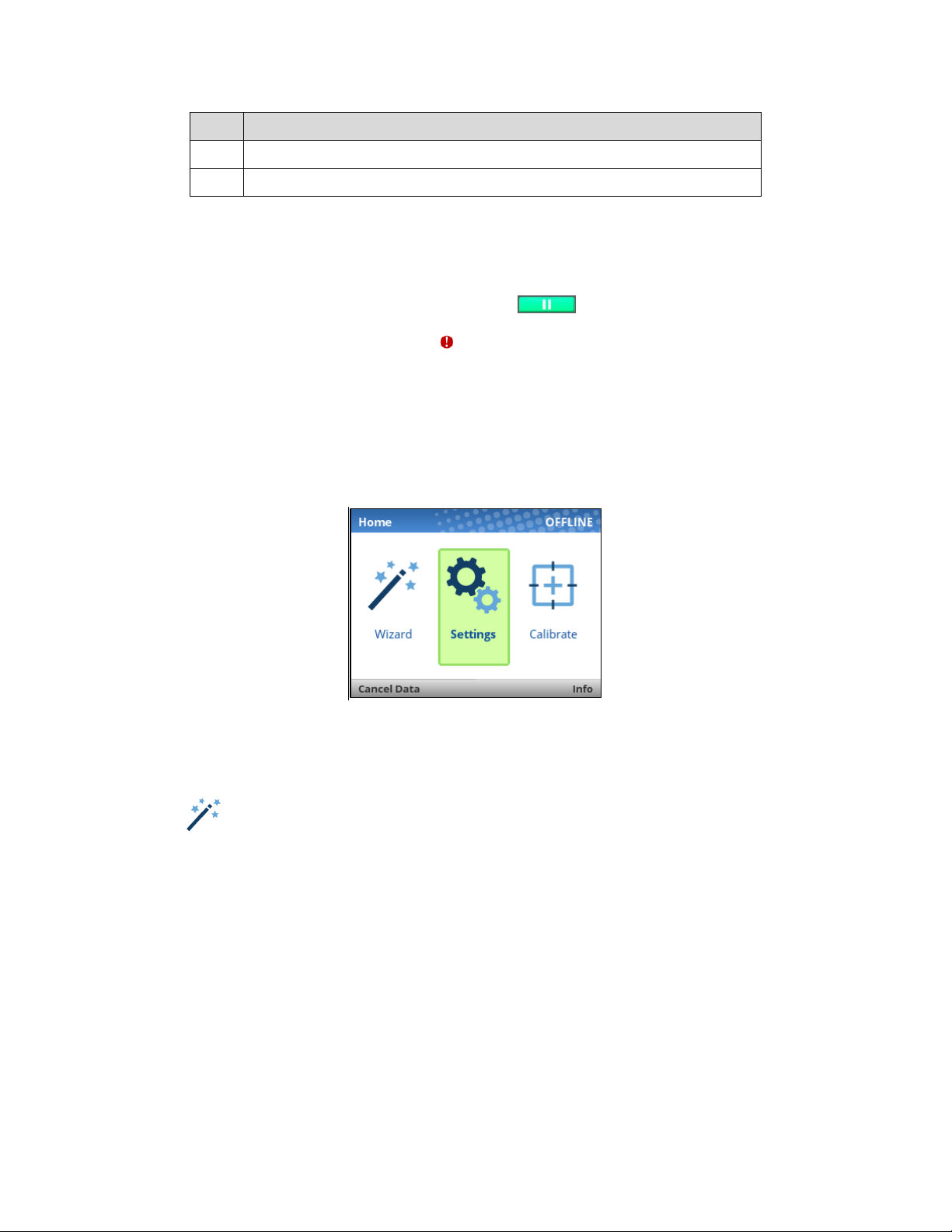
Offline (Home) Screen
When the printer is taken OFFLINE using the PAUSE Key , the UI will show the Home screen.
The Home screen will be the first screen seen by the user when transitioning from ONLINE to OFFLINE.
The right corner of the header may include the symbol in case there are faults in the system not yet
cleared.
Using the navigational keys, the user can move among three options:
• Wizard – Provides Setup Instruction, Web Resources, and other links to the Printronix website via QR
barcodes for Product Support.
• Settings – Provides access to the printer menu system for configuration.
• Calibrate – Makes Calibration convenient and easy to perform when media or ribbon are installed.
There are also functions for the LEFT and RIGHT SOFT keys. The LEFT SOFT key “Cancel Data” is
present if there is data within the buffer and the setting System > Control > Cancel Operation is enabled.
The RIGHT SOFT key labeled “Info” will show the current configuration as text on the UI and the user can
scroll through the data and/or print if desired.
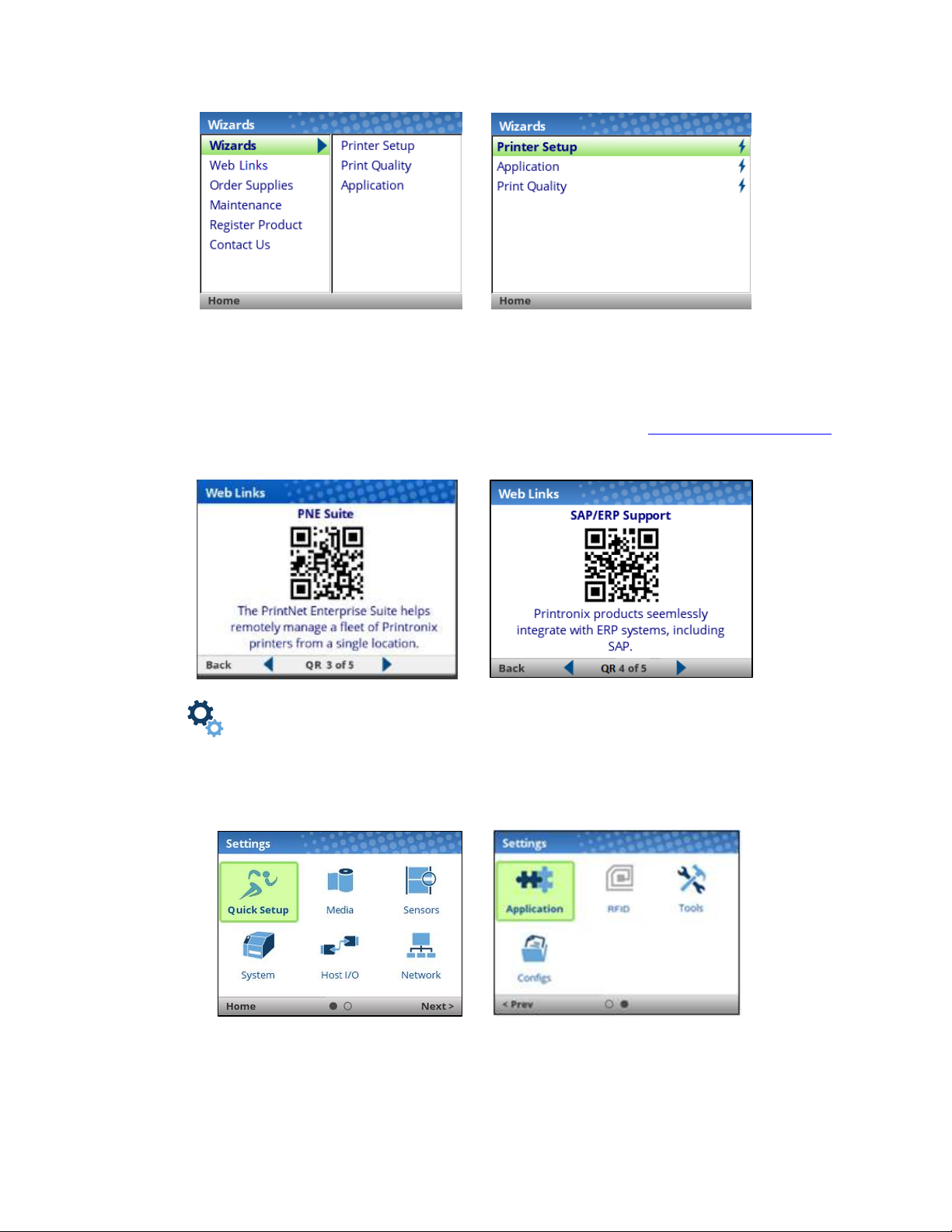
Wizard
The Wizard has several resources available as shown in the next figures. The greatest benefit of the
Wizard is the first subcategory “Wizards”. By highlighting this category (green) and pressing ENTER or the
RIGHT ARROW key, the user can then select the Wizard of choice to run:
• Printer Setup will help the user choose the proper display language, install ribbon & media, set media
and sensor options, calibrate, and run a test pattern to verify the product is working properly.
• Print Quality helps the user adjust the printer mechanically, and set Print Speed and Intensity of the
printer. A test printout helps the user in making the choices.
• Application helps the user setup the menu configuration particular to their label or application coming
from the host system.
22
→
When a Wizard has been completed (all steps executed until the end), the user is required to save their
configurations per usual procedure (see Configuration). The exception to this is the first time the printer is
powered up; in this case, the user is automatically taken into the Printer Setup Wizard and the
configuration is automatically saved to Config 1 when completed.
The Wizard also has support available in the form of QR barcodes for the other categories such as “Web
Links”, “Order Supplies”, etc. These QR barcodes provide links to the website www.PrintronixAutoID.com
to view online videos, manuals, drivers, including places where they can order supplies and register their
product.
→
Settings
The Settings section of the menu represents the heart of the OFFLINE process in which users will peruse
the full menu set, edit menus, run diagnostics, and save configurations. The Settings section begins with
two pages of ICONs that can be selected using the navigational keys and the ENTER button.
NOTE: The printer is shipped with the ENTER button locked. To unlock, press the UP+DOWN arrow keys
simultaneously until you see the message “ENTER SWITCH UNLOCKED”.
23
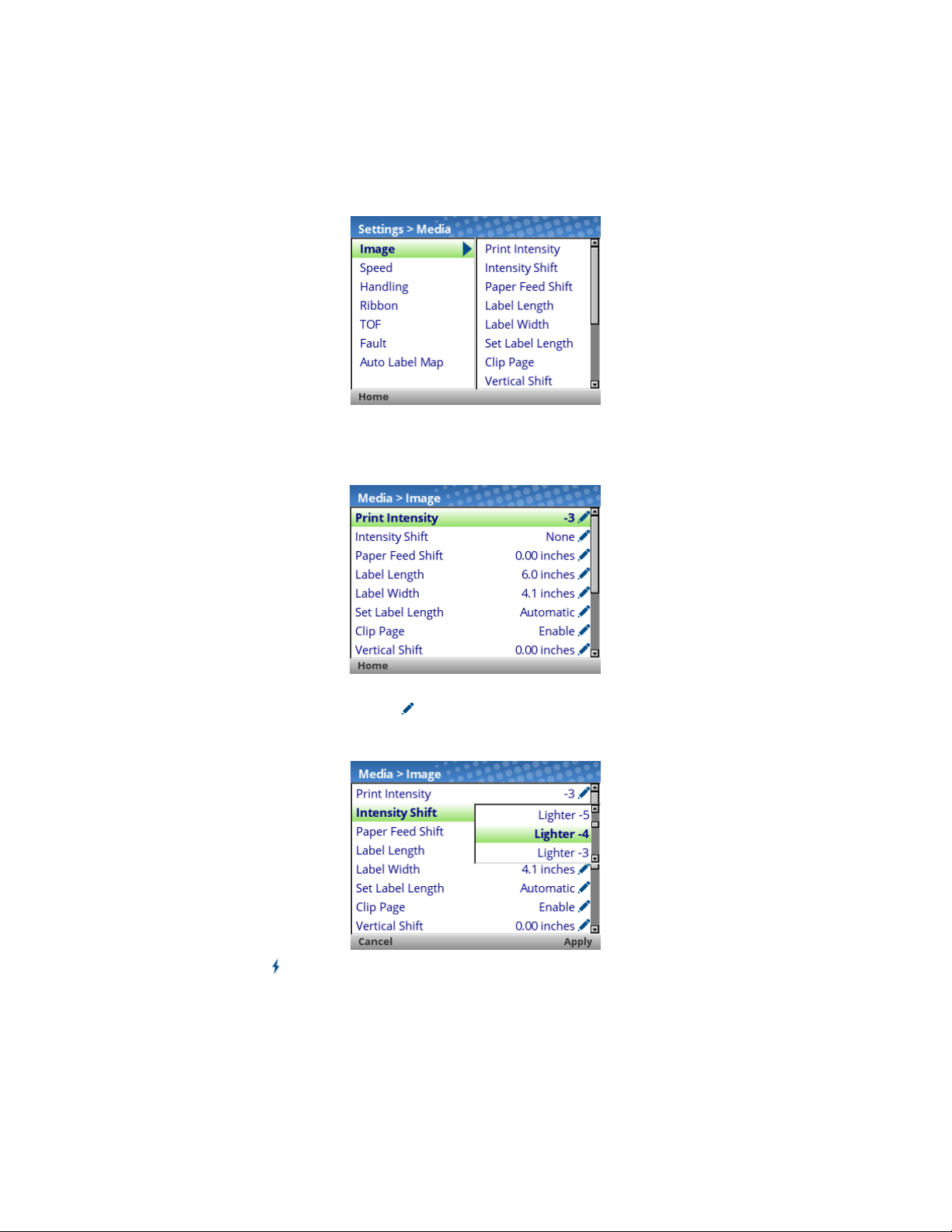
When an ICON is selected, the user moves into the View Level in which the screen is divided with the
submenus on the left and the menu subsections on the right. As they traverse the submenus using the
up/down arrow keys, the menu subsections on the right change so that users can quickly see the menu
contents.
To view the full contents of a particular subsection or edit their menus, the user can either press ENTER or
use the RIGHT ARROW key to get into the Edit Level. Conversely, the user can hit the LEFT ARROW key
to return to the previous screen.
When in the Edit Level, the user can scroll the menus and their values using the up/down arrow keys. The
user can edit any menu that has the icon by pressing the ENTER key, changing the value, and
confirming their change using the “Apply” soft key on the right. There is also a “Cancel” soft key on the left,
if the user does not want to accept the change.
If the menu has a bolt icon, this is an executable menu and pressing the ENTER key will result in a
particular action (e.g., running a print test, clearing statistics). If the menu does not have any icon, then it is
a read-only menu and pressing ENTER key will not have any effect.
24

Calibrate
Calibration must be performed whenever new media or ribbon is installed or any configuration parameter
that affects sensors is modified. Selecting this shortcut ICON and pressing the ENTER key will activate the
Auto-Calibrate function, also available in Sensors > Calibrate > Auto Calibrate.
Fault
When faults occur, the user will be notified with the following screen on the display. The red color is used
to make a clear indication that the printer needs attention.
Users can follow the simple instructions shown in the screen or request additional help with the faults by
using the RIGHT SOFT key “Fault Help” if available. When Fault Help is selected, the user will be provided
a set of screens to help them through the process. However, Fault Help is only offered for faults that are
complex or require several steps with the printer mechanism.
The user can also choose via the LEFT SOFT key to go the “Home” screen, then to the Settings or
Wizard sections to adjust menu values (e.g., change media parameters, load Configs, etc.).
NOTE: The icon will be shown in the upper right corner as a reminder there is a fault that needs to
be cleared. Even when the user has completed all the steps necessary, the icon may continue
to be shown. Some faults are self-clearing in the OFFLINE state while other faults are cleared
only when returning ONLINE. If any fault was not successfully cleared, the Fault screen shown
above will reappear when the user attempts to return ONLINE.
Job in Process
There is no dedicated LED or status indicator for Job in Process. Users will know the printer is receiving
data instead via messages in the circled portion of the ONLINE screen as shown below.
When the printer is in ONLINE mode and data is being received and being processed, the message “Job
in Process” will be shown in the message area. After the job has been printed the message will go away. If
the user is printing in batch mode and the option System > Control > Batch Counter is enabled, the page
count will have priority over the ‘Job in Process’ message.
25

When the printer is in OFFLINE mode and in the Home screen, the LEFT SOFT key will be labeled “Cancel
Data” if there is Data in Buffer when the printer is taken OFFLINE. If there is no Data in Buffer, then the LEFT
SOFT key label will not show anything. In order for the Cancel Data operation to be available, the menu
System > Control > Cancel Operation must be enabled.
Media Handling Modes
Before you load media, you must decide which media handling mode to use:
• Continuous. Prints on the media and sends it out the front of the printer.
• Tear-Off Strip. Prints on the media and sends it out the front until the
positions the trailing edge of the last label over the tear bar for removal.
• Peel-Off. When the optional internal peel-off rewinder is installed, the printer
die-cut labels from the liner without user assistance. A
remind you to remove the label before the next one can be printed. For more information, see
Label Peel-Off.
• Cut. When the optional media cutter is installed, the printer automatically
label is printed or can cut the media after a
Active IGP Emulation cut
Once you have decided on the mode, configure the printer.
command.
specified number of labels have been printed using the
“Remove Label” message will display to
print buffer is empty. It then
prints and peels
cuts media after each
Setting Up the Printer
This section describes the procedures for loading various types of ribbon and media.
The term “media” in this manual refers to all the different kinds of paper, label, or tag stock material that
can be printed on by the printer. Your thermal printer can print on continuous paper, adhesive backed
labels, or non-adhesive tags packaged in roll or fanfold form.
For clarity, all operator touch points are blue in color.
IMPORTANT For best result, use only genuine Printronix supplies. See “Supplies and
CAUTION
Accessories”.
Do not wear rings or other metallic objects while servicing any interior area of
the printer.
CAUTION DO NOT TOUCH the printhead or the electronic components under the pivoting
deck. The discharge of electrostatic energy that accumulates on the surface of
the human body or other surfaces can damage or destroy the printhead or
electronic components used in this device.
CAUTION Do not close the pivoting deck without label stock installed between the
printhead and the platen, because debris on the platen may damage the
printhead.
IMPORTANT Adhesive backed labels that DO NOT lay flat on the liner can jam the printer.
This can cause the label to peel off the liner. The exposed edges can stick to the
label guides and rollers inside the printer.
If you run out of labels while printing, do not turn off the printer while reloading
labels, because you can lose data.
26

27
Note: Please follow the direction when
installing the ribbon spindle.
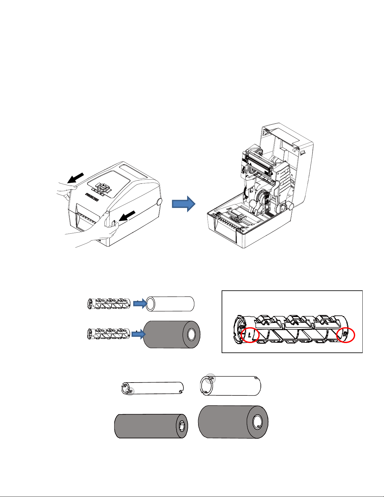
Loading Ribbon
For direct thermal media (no ribbon required), go to “Loading Media” section.
IMPORTANT Clean the printhead, platen roller, and media sensors every time you change the
ribbon. See Cleaning the Printhead, Platen Roller, Media Sensors/Damper.
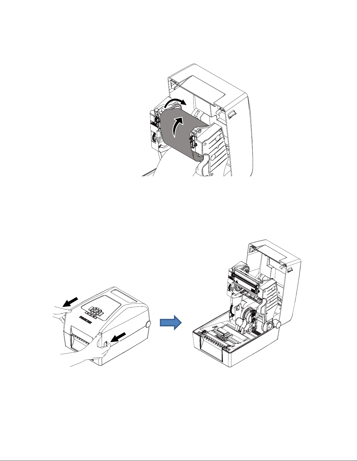
1. Open the printer top cover by pulling the blue levers, located on each side, toward the front of the
printer, then lift the top cover.
2. T800 supports 3 kinds of paper core for ribbon.
▪ For 1 inch paper core without notches, please insert the ribbon spindles into the paper core and
ribbon.
▪ For 1 inch & 0.5 inch paper core with notches, do not need to install the ribbon spindles.
28
Note: Please insert the right side of spindle
first. Then, insert the left side to the
hole at the left side of the blue hub.
Ribbon
Paper core for rewinding
the used ribbon
3. Install the paper core and ribbon to the hubs. For 0.5 or 1 inch paper roll with notches on both sides,
please insert them at the hubs directly.
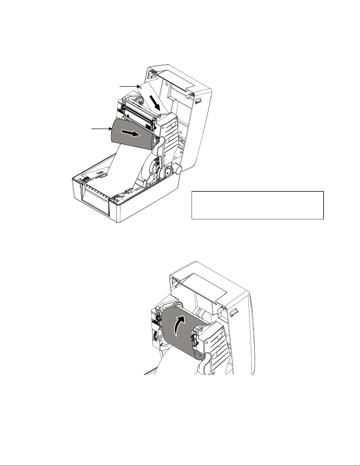
4. Pull the leader of the ribbon through the print head and stick the leader of the ribbon onto the ribbon
rewind paper core.
29
5. Turn the blue ribbon rewind hub until the ribbon plastic leader is thoroughly wound and the black
section of the ribbon covers the print head.
Loading Media
1. Open the printer top cover by pulling the blue levers , located on each side, toward the front of the
printer, then lift the top cover.
30

Media guide
Black mark
sensor
RFID antenna
slide (if equipped)
2. Separate and hold open the blue media holders.
3. Place the roll between the holders and close them onto the core.
4. Separate the blue media guides.
Note:
▪ For black mark media or media with notch or holes used to indicate label length, the blue Black
Mark sensor is moveable. Slide it to correct position for detecting.
▪ For RFID model, slide the blue antenna slide to the correct position.
31

5. Place the paper, printing side face up, through the media sensor and place the label leading edge onto
the platen roller. Move the blue media guides to fit the label width.
6. Press down on both sides of the top cover to close it gently.
7. Initiate Auto Calibrate via the Home Screen ICON , selecting this shortcut ICON and pressing the
ENTER key will activate the Auto-Calibrate function. Calibration may also be activated via the Sensors
menus within the Settings section (Sensors > Calibrate > Auto Calibrate).
Note: Calibration must be performed whenever new media or ribbon is installed or any configuration
parameter that affects the sensors is modified.
Your printer is equipped with media sensors that detect the top-of-form position on media with label length
indicators (gaps, notches, holes, or black marks). These sensors also detect when a Paper Out condition
exists.
32

Loading External Media
If using either an external media holder or folded labels, feed the media through the rear external label
entrance chute.
1. Open the printer top cover by pulling the blue levers, located on each side, toward the front of the
printer, then lift the top cover.
2. Separate and hold open the media holders.
3. Set the media holder lock switch to down to keep the media holders separated.
4. Feed the paper from rear external label entrance chute, printing side face up, through the media
sensor and place the label leading edge onto the platen roller. Move the media guides to fit the label
width.
5. Press down on both sides of the top cover to close it gently.
6. Initiate Auto Calibrate via the Home Screen ICON , selecting this shortcut ICON and pressing the
ENTER key will activate the Auto-Calibrate function or initiate calibration via the Sensors menus
33

Black Mark Sensor (Moveable/ Reflective)
Gap Sensor (Fixed/ Transmissive)
The black mark sensor position is moveable.
Move the triangular mark (
▽) directly into the
path of the black mark on the underside of the
media, or extraneous cut-out (notch or hole) to be
used for detection. Please make sure there is no
dark pre-printing or RFID tags that could cause
false black mark detection or paper out faults
within the path of the sensor.
The gap sensor is in a fixed position in the center,
covering an offset 4 mm to right or 7 mm to left
from center. The default is located in center of
offset 4 mm. Please make sure the media has no
vertical gap, rounded die-cut label corners or dark
pre-printing that could cause false gap detection
or paper out faults.
Gap sensor
(Transmitter)
Gap sensor (Receiver)
Black Mark sensor
(Transmitter &
Receiver)
within the Settings section (Sensors > Calibrate > Auto Calibrate).
Positioning the Media Sensors
Your printer is equipped with two media sensors that detect the top-of-form position on media with label
length indicators (gaps, notches, holes, or black marks). These sensors also detect when a Paper Out
condition exists. You may select via the Control Panel which sensor will be used, based on the type of
media to be printed.
34

Avoid Dark
Pre-printing
Extraneous
Cut-out
Vertical Gap and Rounded
Die-cut Label Corners
35

Sensing Different Media Types
The printer’s media sensors can detect the different types of label length
media types. This is accomplished by selecting
Sensors > Control > Gap/Mark Sensor menu or within the “Printer Setup” Wizard.
1. Press the PAUSE key to place the printer OFFLINE (Home Screen).
2. Find the Settings ICON and press ENTER.
3. Press the UP + DOWN ARROW keys together until “ENTER SWITCH UNLOCKED” displays.
4. Find the Sensors ICON and press ENTER.
5. Select the “Control” submenu and press ENTER.
6. Find the “Gap/Mark Sensor” option and press ENTER to edit this menu. Find the option that matches
the type of label length indicators on the installed media displays:
Disable. Select when using media with no label length indicators (no gaps, notches, holes, or black
marks) or when you want the printer to ignore all existing label length indicators on the installed media.
Mark. Select when using media that has horizontal black marks
liner or tag stock or when using media with notches or holes as label length
Gap. Select when using media with a liner space between die-cut
located on the topside of the label.
the correct sensor option: Gap, Mark, or Disable under
indicators on a large variety of
located on the underside of the label
indicators.
labels or has horizontal black marks
NOTE: When you select Disable, the length of each label is based on the
Length menu or the value
sent via host software.
NOTE: If the printer detects a false PAPER OUT message when you change
vice-versa, find the Home Screen and run Calibrate
or
7. Press ENTER to enable the displayed option or use the RIGHT SOFT key labeled “Apply”. An asterisk
.
(*) appears next to the selection
8. Press the PAUSE key or the LEFT SOFT key labeled “Home” to return to the Home Screen.
9. Review Media with Gaps
10.
1. Media with a horizontal liner space between die-cut labels or horizontal black marks located on the
upper side of the label liner.
2. Select “Gap” in the Sensors > Control > Gap/Mark Sensor menu.
3. Perform an Auto Calibrate. See Running Auto Calibrate on page 38.
11. Calibrating the Media Sensors on page 37. Perform the Auto Calibrate procedure per Running Auto
Calibrate on page 38.
Media > Image > Label
to Gap or Mark sensing
36

Sensors > Control > Gap/Mark Sensor
The available options specify the sensor type needed for detecting the
Top-of- Form position on media with label length indicators (gaps, notches,
holes, or black marks).
Disable
Select when using media with no label length
indicators (no gaps, notches, holes, or black marks), or
when you want the printer to ignore all existing label
length indicators on the installed media.
Mark
Select when using media that has horizontal black
marks located on the underside of the label liner or tag
stock. Also used for tag stock with notches, or holes
used as label length indicators.
Gap
Select when using media with a horizontal liner space
between die-cut labels or horizontal black marks
located on the upper side of the label liner.
Media with No Label Length Indicators
1. When using media without label length indicators (no gaps, notches,
want to ignore all existing length indicators,
the center of the media so it can detect when a
2. Select “Disable” in the Sensors > Control > Gap/Mark Sensor menu. See Section “Sensors > Control”.
3. Perform an Auto Calibrate.
place the triangle mark ▽ on the media sensor assembly in
Paper Out condition exists.
holes, or marks) or when you
Media with Underside Horizontal Black Marks
1. Position the triangle mark
located
2. Select “Mark” in the Sensors > Control > Gap/Mark Sensor menu.
3. Perform an Auto Calibrate.
on the underside of media.
▽ on the media sensor assembly in the center of the horizontal black marks
Media with Gaps, Notches or Holes
1. Position the triangle mark
in media.
2. Select “Mark” in the Sensors > Control > Gap/Mark Sensor menu.
3. Perform an Auto Calibrate. See Running Auto Calibrate on page 38.
▽ on the media sensor assembly in the path of the gaps, notches, or holes
Media with Gaps
4. Media with a horizontal liner space between die-cut labels or horizontal black marks located on the
upper side of the label liner.
5. Select “Gap” in the Sensors > Control > Gap/Mark Sensor menu.
6. Perform an Auto Calibrate. See Running Auto Calibrate on page 38.
37

Calibrating the Media Sensors
Due to manufacturing differences in media, the media sensors
the label and the liner or the label
a
label or display a fault message such as “GAP NOT DETECTED” or “PAPER OUT”.
Media sensor sensitivity and reliability can be improved by changing the
Thresh and/or Sensors > Control > Paper Out Thresh values. You can change
automatically by performing an Auto Calibrate or Manual Calibrate procedure from the Sensors >
Calibrate menu section. (The changes take effect immediately within the current configuration menu.)
Auto or Manual Calibrate is completed successfully when the displayed
matches that of the installed media. When
from the
selected, the Sensed Distance should match the length
leading edge of the next black
When you have completed Auto or Manual Calibrate, you can verify the new
the FEED key several times. Each time you
correct Top-of-Form
Once you confirm the correct values, save them to the desired configuration
printer.
trailing edge of one gap to the trailing edge of the next gap (or one label + one gap). When Mark is
position of the next label.
and the black mark. When this occurs, the printer may intermittently skip
Gap is selected, the Sensed Distance should match the length
mark.
press FEED, media advances one label and stops at the
may have difficulty differentiating between
Sensors > Control > Gap/Mark
these values manually or
Sensed Distance value correctly
from the leading edge of one black mark to the
values are correct by pressing
menu before powering off the
Running Auto Calibrate
You can initiate Auto Calibrate via the Home Screen ICON or via the Sensors menus within the
Settings section.
NOTE: Verify that the Gap/Mark Sensor option (Gap, Mark, or Disable) matches the installed media.
Check that the media sensors are horizontally positioned to permit
indicators. See Positioning the Media Sensors.
Make sure the Media > Image > Label Length value matches the physical length of the installed
media. Entering the
calibrate for long labels (so actual gaps, notches, and marks can be detected) and reduce the
amount of media advanced for short labels.
If you try to do an Auto Calibrate when Peel-Off Media Handling is
display “CANNOT CALIBRATE” error. Before you can do an Auto Calibrate, you must select
another media handling mode.
1. Press the PAUSE key to place the printer OFFLINE (Home Screen).
2. Select the Calibrate ICON and press the ENTER key.
3. Media advances until it can accurately detect the label length
Top-of-Form position. The Sensed
4. Auto Calibrate is successful when the Sensed Distance value correctly
media:
Gap/Mark Sensor = Gap:
length of one gap, notch, or hole.
Gap/Mark Sensor = Mark: The Sensed Distance value is the
of one black mark to the
Gap/Mark Sensor = Disable: Not applicable. If Gap/Mark Sensor is
Distance value will not be updated.
If “GAP NOT DETECTED” displays, run Auto Calibrate again.
correct length forces the printer to advance media far enough during
Distance value will then display for one second.
The Sensed Distance value is the physical length of one label plus the
physical distance from the leading edge
leading edge of the next black mark.
sensing of the label length
enabled, the LCD will
indicators and then stops at the
matches that of the installed
set to Disable, the Sensed
38

If Auto Calibrate continues to end with an incorrect Sensed Distance
message displayed, refer to Running Manual Calibrate on page 40.
NOTE: The amount of media sampled during Auto Calibrate is based on the
transitions detected, without error, between a label and its label length indicators.
5. Press the FEED key several times. Each time you press FEED, the media
and stops.
NOTE: After a form feed, the position of the leading edge of the next label
Media Handling mode selected under Media > Handling > Media Handling menu. Tear-Off
Strip Media Handling will position the label edge at the tear bar, while Continuous will position
the label edge under the printhead.
6. Once the Sensed Distance value is confirmed, you can save them to
before powering off the printer or you can press the PAUSE key and the printer will automatically
display a reminder message that your changes have not been saved and to select one of four possible
choices.
7. Once completed the printer will go ONLINE.
value displayed or a fault
length of a label and
advances one label length
depends on the type of
a desired configuration menu
Running Media Profile
The Media Profile printout shows the relationship of the Paper Out Threshold
values, illustrates if and when each label length
the label length
difficult media. This includes pre-printed labels and
Once Media Profile is initiated, the printer will continue to advance media and print the profile in landscape
orientation until you press ENTER to stop printing.
indicators and the label. The profile printout (shown here) helps you set the thresholds for
indicator is detected, and shows the difference between
labels with poor gap/media dynamic range.
and the Gap/Mark Threshold
NOTE: Verify the Sensors > Control > Gap/Mark Sensor option (Gap,
installed media.
You will need a minimum installed label width of two inches to support
Ensure the media sensors are horizontally positioned to permit
indicators. Positioning the Media Sensors.
Ensure the Media > Handling > Print Mode option matches the media installed. Select “Direct”
for heat sensitive media
required).
1. Press the PAUSE key to place the printer OFFLINE (Home Screen).
2. Find the Settings ICON and press ENTER.
3. Press the up and down arrow keys together until “ENTER SWITCH UNLOCKED” displays.
4. Find the Sensors ICON and press ENTER.
5. Select the “Diagnostic” submenu and press ENTER.
6. Find “Media Profile/Profile Print” and then press ENTER to start the profile printing process.
The printer will advance media and continue to print a dynamic profile image depicting the relationship
of the label and any label length indicators detected.
7. Press
8. Press the PAUSE key to place the printer OFFLINE (Home Screen).
ENTER to stop the profile printing.
(no ribbon required) or “Transfer” for thermal transfer media (ribbon
Mark, or Disable) matches the
the Profile printout.
sensing of the label length
NOTE: The Gap/Mark and Paper Out Threshold values shown on the Profile printout represent the
last values determined from a successful Auto or Manual Calibrate or the factory default
39

values if no Auto or Manual Calibrate was performed.
Figure 1 Media Profile Printout
Gap Sensing
This figure shows a Media Profile printout of a RFID label where the Gap/Mark
Sensors > Control menu.
In this example, the gap threshold value the printer selected (represented by the Gap/Mark dotted line) is
too close to the value seen for the RFID antenna.
the gap (top-of-form).
NOTE: Refer to the RFID Labeling Reference Manual for full details on how to set up the printer to properly
run RFID labels.
This may cause the printer to falsely use the antenna as
Sensor is set to Gap in the
40

To avoid this problem, increase the Threshold Range value to 60% or 70% in the Sensors > Calibrate>
Threshold Range (the default is 50%), then perform a Running Auto Calibrate page 38.
Any changes to Threshold Range will not take effect until you run an
This will raise the Gap/Mark threshold high enough so that the printer will not
gap (top-of-form).
Auto Calibrate again.
falsely use the antenna as the
Running Manual Calibrate
Manual Calibrate should be performed only when the values derived from
media sensors’ ability to sense label length
the Sensors > Diagnostics section.
indicators on the installed media. Manual Calibrate is located in
Auto Calibrate fail to improve the
NOTE: Verify the Gap/Mark Sensor option (Gap, Mark, or Disable) matches the installed media.
Ensure the media sensors are horizontally positioned to permit sensing of the label length
indicators.
Ensure the Media > Handling > Print Mode option matches the media installed. Select “Direct”
for heat sensitive media (no ribbon required) or “Transfer” for thermal transfer media (ribbon
required).
If you try to do a Manual Calibrate when Peel-Off Media Handling is
display a “CANNOT CALIBRATE” error. Before you can do a Manual Calibrate, you must
select another
1. Press the PAUSE key to place the printer OFFLINE (Home Screen).
media handling mode.
enabled, the LCD will
2. Find the Settings ICON and press ENTER.
3. Press the up and down arrow keys together until “ENTER SWITCH UNLOCKED” displays.
4. Find the Sensors ICON and press ENTER.
41

5. Select the “Diagnostics” submenu and press
6. Find “Manual Calibrate” and then press ENTER to start the process.
7. Follow the instructions displayed on the LCD and press the
8. During the last step of Manual Calibrate, the printer will advance the
label length indicators and stop at the
display for one second. The calibrate is successful when the Sensed Distance value correctly matches
that of the installed media. If “CALIBRATION FAIL” error displays, run Manual Calibrate again.
NOTE: The amount of media sampled during Manual Calibrate is based on
the transitions detected without error, between a label and its label length indicators.
9. Press the PAUSE key to place the printer OFFLINE (Home Screen).
10. Press the FEED key several times. Each time you press FEED, the media advances one label length
and stops.
NOTE: After a form feed, the position of the leading edge of the next label
Media Handling mode selected via Media > Handling > Media Handling. Tear-Off Strip Media
Handling positions the label edge at the tear bar, while Continuous positions the label edge
under the printhead.
11. Once the correct values are confirmed, save them to the desired
off the printer.
ENTER.
ENTER key to move to the next step.
media and attempt to detect the
Top-of-Form position. The Sensed Distance value will then
the length of a label and
depends on the type of
configuration menu before powering
42

Label Peel-Off (Optional)
You can set up the printer to automatically peel die-cut labels off their liner
one at a time while rewinding the liner. For installation information, refer to Appendix D.
(backing) and dispense them
Loading Media Using Peel-Off Mode
1. Please follow Loading Media on page 30 above to load the media and calibrate the sensors before the
next step to avoid paper jams.
2. Open the peel-off front door.
3. Thread the media (label and liner) over the tear bar and around the
opening at the bottom of the front door. The label liner will be fed to the floor.
peel-off roller, then through the
43

4. Close the peel-off front door.
5. Press down on both sides of the top cover to close.
Configuring the Printer Menu
1. Press the PAUSE key to place the printer OFFLINE (Home Screen).
2. Set Media Handling to “Peel-Off” within the Application Wizard or directly in Media > Handling > Media
Handling menu.
3. Back to ONLINE.
4. The printer is ready on Label Peel-Off Mode.
5. Press the FEED key. The label advances to the peel-off position, and
LCD.
6. Manually remove the peeled label from the printer.
“Remove Label” displays on the
44

Media Cutter (Optional)
You can set up the printer to automatically cut printed media when the media exits the printer. For
installation information, refer to Appendix C.
Loading Media Using Cutter Mode
1. Please follow "Loading Media" above to load the media and calibrate the sensors before the next step
to avoid paper jams.
2. Thread the media through the opening at the media cutter.
Configuring the Printer Menu
1. Press the PAUSE key to place the printer OFFLINE (Home Screen).
2. Set Media Handling to “Cut” within the Application Wizard or directly in Media > Handling > Media
Handling menu.
3. Back to ONLINE.
4. The printer is ready on Cut Mode.
5. Press FEED key to test.
45

Printing Adjustments
Printhead Burn Line Adjustment
The print head burn line adjustment are used to fine tune the print quality for different thicknesses of
media. Adjust the print head’s burn line forward or backward as it relates to the platen roller.
The print head burn line default is set for general purpose printing media (plain paper and paper thickness
less than 0.20mm). In general, print head burn line adjustment will not be required. If you have poor print
quality, please try changing the print speed or print intensity first, before moving the burn line.
Poor print quality when using paper thicker than 0.20mm may be due to the print head burn line not being
at the optimized position. Please refer to the steps below to improve the print quality.
1. Open the printer to remove the front cover.
2. Adjust the knobs on right and left sides to get your best print quality. There are 7 levels of adjustment.
Adjust both knobs to the same level. The default setting is 4.
3. Adjust the burn line position and test print as necessary until the printed image is clear.
4. Re-install the front cover after adjusting.
46

Cleaning
Depending on the media used, the printer may accumulate residues (media
by-product of normal printing. To maintain top
cleaning the printer
periodically.
printing quality, you should remove these residues by
WARNING Set the printer power switch to O (Off) prior to performing any cleaning
Leave the power cord connected to keep the printer grounded
risk of electrostatic damage.
dust, adhesives, etc.) as a
tasks.
and to reduce the
IMPORTANT When the printer is powered Off, menu settings that were changed and not
saved and any print data remaining in the print buffer will be lost. To prevent the
loss of recent menu changes, see Configuration setting on page 49.
CAUTION • Do not wear rings or other metallic objects while cleaning any interior area of
the printer.
• Use only the cleaning agents recommended in this section. Use of
cleaners may damage the printer and void its warranty.
• Do not spray or drip liquid cleaning solutions directly into the
the solution on a clean lint-free cloth and then apply
printer.
the dampened cloth to the
• Do not use canned air in the interior of the printer as it can blow dust
debris onto sensors and other critical components.
• Only use a vacuum cleaner with a nozzle and hose that are
grounded to drain off static build up.
conductive and
• All reference in these procedures for use of isopropyl alcohol
99% or greater isopropyl alcohol content be used to
corrosion to the printhead.
reduce the risk of moisture
other
printer. Apply
and
requires that a
Exterior Cleaning
Clean the exterior surfaces with a clean, lint-free cloth. If necessary, use a
cleaning solution.
mild detergent or desktop
Interior Cleaning
Clean the interior of the printer by removing any dirt and lint with a vacuum
use a brush with soft non-metallic bristles.
cleaner, as described above, or
Cleaning the Printhead, Platen Roller, Media Sensors/Damper
NOTE: Even though the printhead, platen roller, media sensors and media
listed in these cleaning procedures, debris
travel to the printhead area and therefore should be cleaned and examined each time the
printhead is cleaned and in the order shown.
and adhesive on these components can ultimately
Printhead Cleaning
As you use your printer, the printhead may become dirty with ribbon residue
result in poor print quality. Keeping the
• Cleaning Agent - Clean the printhead using a Printhead Cleaning Pen,
or an Isopropyl Alcohol Wipe, Printronix PN
• Schedule - Clean the printhead each time you install a new roll of ribbon
mode) or when you install a new roll or box of
printhead clean will help maintain its life.
254945-901.
media (direct thermal print mode).
and label adhesives which can
damper are individually
Printronix PN 203502-002
(thermal transfer print
47

WARNING If you have just been printing, allow one minute for the printhead to cool
down to avoid burns from accidental printhead contact.
CAUTION • Avoid electrostatic damage to the printhead by first making hand contact with
an unpainted part of the printer frame or by using an anti-static wrist strap
grounded to the printer frame.
• Do not use hard, sharp or abrasive objects to remove residue from the
printhead.
• Do not touch the heating element surface of the printhead with your hands to
avoid printhead corrosion. Any accidental skin contact with the element surface
should be immediately followed by a thorough cleaning with a Printhead
Cleaning Pen or an Isopropyl Alcohol Wipe.
• The heating element surface should be free from any condensation to avoid
corrosion.
1. Remove the media and ribbon, if installed.
2. Clean the printhead by gently rubbing an Isopropyl Alcohol Wipe or the felt tip of a Printhead Cleaning
Pen across the print heads’ light-brown heating elements area. Allow the printhead to dry for one
minute before reloading ribbon or media.
NOTE: Even after a thorough cleaning with a Printhead Cleaning Pen or
see printouts with voids or streaks. This may be the result of baked-on ribbon resin that can be
hard to remove when normal cleaning cycles are not maintained. Try using a Thermal Printer
Cleaning Card 4”W x 6”L PN TSCCC-4-15. When using a cleaning card, follow the directions
on the packaging.
Alcohol Wipe, you may still
Platen Roller Cleaning
Label parts, media dust, and adhesive residue on the platen can degrade print
your label image.
• Cleaning Agent - Use an isopropyl alcohol wipe or small amount of
cloth to clean the platen roller.
• Schedule - Clean the platen roller each time you clean the printhead.
1. Clean the platen roller by first removing any label parts from its surface by
alcohol wipe or clean cloth moistened with
debris, or label
entire surface area.
adhesive. The platen roller can be rotated forward by hand to access and clean its
isopropyl alcohol to remove any remaining paper dust,
NOTE: Even though power is removed from the platen motor, some drag will
platen.
2. Check the platen roller for razor cuts, nicks, and gouges that may cause
This type of damage usually requires platen
roller replacement.
quality and cause voids in
isopropyl alcohol on a clean
hand. Then use an isopropyl
be felt as you rotate the
voids in the printed image.
Media Sensor Cleaning
The upper and lower media sensors should be cleaned to ensure reliable Top of Form and Paper Out
sensing.
CAUTION Do not use isopropyl alcohol, solvents, or abrasive agents to clean the
media sensor as they can damage the sensors lens cover.
• Cleaning Agent - Use a brush with soft, non-metallic bristles or a vacuum cleaner, described
above, to remove paper dust.
lower
48

NOTE: An Isopropyl Alcohol Wipe or Printhead Cleaning Pen can be used to
from the upper sensor.
• Schedule - Clean the media sensors each time you clean the printhead.
1. Brush away or vacuum any dust or debris from the upper and lower
pen or wipe.
sensor before using the cleaning
remove label adhesive
Cutter Option Cleaning
The cutter requires only periodic cleaning.
WARNING Keep your fingers away from the cutter blades. They are sharp.
Perform the following procedure whenever too much dust or debris is visible.
1. Set the printer power switch to O (Off).
2. Place the cutter in the down (open) position.
3. Use a vacuum or can of compressed air with a nozzle around the area of
any dust or debris.
4. Use a cloth with a light amount of WD-40 oil to clean adhesive from the cutter blade and upper or lower
stainless steel cutter guides. Adhesive oil
to prevent
dust attraction.
must be cleaned from the blade and guides with a dry cloth
the cutter blade to remove
CAUTION Do not use isopropyl alcohol to clean the cutter blade – it dissolves oils
required for lubrication.
5. Place the cutter in the up (closed) position.
6. Properly route the media through the printer and cutter.
7. Set the printer power switch to | (On).
8. Test the printer cutting operation by running a test print within the Tools > Print Tests > Run Test
menu.
49

3 Printer Settings
Overview
This chapter provides information about:
• Setting, saving, modifying, and printing configurations
• Structure of the configuration
• Menu and Configuration Parameters
Setting Printer Configuration Parameters
Configuration parameters are set from the control panel and stored into the printer’s flash memory. The
parameters define how the printer will respond to
The Settings section is where the complete set of menus and configuration parameters are located.
The T800 menu system is three levels deep and consists of the ICON Level, View Level, and Edit Level.
The ICON Level. The top level of the menu system is known as the ICON Level and consists of two
screens as shown below. The green shading shows the current icon selected. The arrow keys are used to
select different icons (and even move between screens).
command and interface signals from the host computer.
IMPORTANT The RFID icon is grey to symbolize that these options are not installed. When
colored grey, an icon cannot be selected.
When the desired icon is highlighted, the user must press
The View Level. The 2nd level of the menu system is known as the View Level and is separated into a left
and right screen. On the left side are submenus, and on the right are the actual menus or configuration
parameters. The up/down arrow keys will move to different submenus (highlighted in green) and the right
side will show a preview of the configuration parameters available for that submenu.
ENTER to move into the View Level.
50

When the desired submenu is highlighted, the user can press
move into the Edit Level. Likewise, the user can use the LEFT ARROW key to move back to the ICON
Level.
The Edit Level. The last level of the menu system is known as the Edit Level and contains all the
configuration parameters for a given submenu. The user can scroll through the menus using the up/down
arrow keys to view the current configuration values.
ENTER or the RIGHT ARROW key to
For menus that have the edit icon , the user can modify the value by pressing the
Edit Mode. If the menu has a bolt icon, this is an executable menu and pressing the ENTER key will
result in a particular action (e.g., running a print test, clearing statistics). If the menu does not have any
icon, then it is a read-only menu and pressing ENTER key will not have any effect.
ENTER key to enter
IMPORTANT When entering the Edit Mode, a message “ENTER SWITCH LOCKED” may
appear. In this case, the user will not be allowed to enter Edit Mode until the
panel is unlocked. To unlock the configuration, press the UP+DOWN arrow keys
simultaneously until you see the message “ENTER SWITCH UNLOCKED”.
In the Edit Mode, depending on the type of menu, the user may be given a pull-down menu of options or
cycle through a set of numbers with an asterisk next to the current value. In cases where large numbers,
strings, or network IP addresses must be entered, a virtual keyboard will be shown in which users can
navigate to different characters or numbers. The examples below show Edit Mode with a pull-down menu
and a virtual keyboard.
51

When users are in Edit Mode, they can change to a new value by either pressing the
using the RIGHT SOFT key to “Apply”. Likewise, the users can exit Edit Mode without any modification to
the menu by using the LEFT SOFT key to “Cancel” the operation.
For menus with an action icon , the user can execute the particular action by pressing the
For menus without any icon, these are read-only menus and cannot be modified.
ENTER key, or
ENTER key.
IMPORTANT Some sensitive menu operations require the user to confirm they want to
proceed. For example, menu operations that clear logs, delete configuration,
delete files, etc. In these cases, a message will appear on the screen asking
them to confirm by pressing “OK” with one of the soft keys.
Users can return to the View Level by pressing the LEFT ARROW key or go to the Home menu screen by
using the LEFT SOFT key labeled “Home”.
NOTE: Changing menu values as described in this section only changes the Current Configuration.
The Current Configuration is stored in DRAM and is in effect only while the printer is powered
on. To store a configuration permanently into FLASH memory, see Configurations section on
page 49.
Saving a Configuration
When you make a change to the configuration menus, your changes reside in the Current Configuration
saved in DRAM. The Current Configuration is in effect while the printer is powered on.
If you want to save your configuration permanently into FLASH memory, then you have two options:
• Save the configuration by following the instructions within the Auto Save feature when you return to
the ONLINE state.
• Select the
Save Config.
Your printer by default has a Factory Configuration. You can save up to eight different configurations to
meet unique print job requirements. Using the Configs > Control section, you can save, load, print, delete,
and choose which configuration will be active at power-up.
Configs icon under Settings and save the configuration with Configs > Control >
52

Auto Save Configuration
If you make any changes to the current configuration menu items and do not save them manually via the
Configs > Control > Save Config menu, you will be prompted to save the changes just before you place the
printer ONLINE with the screen shown below.
The Active Configuration is defined as the power-up configuration or last loaded configuration. There are
three possible cases with this choice depending on the state of the printer:
• If the Active Configuration is one of the eight user-defined configurations, the Active Configuration will
be saved and made the Power-Up Configuration.
• If the Active Configuration is the Factory Configuration, the printer will save the configuration to the first
free (unsaved) configuration and make that open configuration the Power-Up Config.
• If the Active Configuration is the Factory Configuration and there are no free (unsaved) configurations,
then the user will be informed with a message and asked to save the changes manually. The printer
will return to the Home Screen.
The Current Configuration is the configuration stored in DRAM. If the user selects this option, the
configuration will not be saved into FLASH memory permanently but will continue to be active.
The user also has the option of cancelling their changes by loading either the Active Configuration or the
Factory Configuration.
Once the selection is made, the user will return to the ONLINE state automatically.
Naming Configurations
You may specify a 15-character name which can be used to refer to a configuration in the Configs >
Custom section. The name you enter for a configuration will then be used everywhere within the
Config
section. The names can be cleared by using the Configs > Custom > Reset Cfg Names menu.
53

When a configuration to name is selected, a virtual keyboard will be provided for the user to enter the
name desired. The navigation keys can be used to find characters with the ENTER button used to select
them. When the string is complete, the user should use the RIGHT SOFT key labelled “Apply”.
Loading a Configuration
You can specify any one of the nine configurations (1-8 or Factory) to load into DRAM using the Configs >
Control > Load Config menu. If the selected configuration has not been saved, the user will be warned with
a “CONFIG DOES NOT EXIST” message on the pane.
54

Specifying a Power-Up Configuration
You can specify any one of the nine configurations (1-8 or Factory) as the
Configs > Control > Power-Up Config menu. If the selected configuration has not been saved, the user will
be warned with a “CONFIG DOES NOT EXIST” message on the panel.
power-up configuration using the
Modifying a Saved Configuration
Configurations can be modified and saved (updated) as often as desired. You can load a configuration of
choice with Configs > Control > Load Config, change the menu or configuration parameter of interest and
either use the Auto Save feature or return to the Configs > Control > Save Config menu to save the
changes.
Viewing the Current Configuration
The Current Configuration can be easily viewed on the control panel by selecting the RIGHT SOFT key
labeled “Info” on the Home screen. This will provide the same information in a Configuration Printout
except it is viewable on the control panel.
As can be seen from the picture, the user can scroll through the configuration values and choose to print
the configuration using the RIGHT SOFT key labelled “Print”.
Printing a Configuration
We recommend that you print and store all saved configurations for future
a list of the parameters that were set when
the Configs > Control > Print Config menu. That menu has the following options:
• Current (the default)
• Factory
• Power-Up
• All
• Saved Configurations 1-8
you configured the printer. Configuration can be printed using
reference. The printout provides
55

Screen #1
Quick Setup
Media
Sensors
Application
Configs
Admin User
Media
Image
Speed
Handling
Ribbon
Top of Form
Faults
Auto Label Map
Sensors
Control
Calibrate
Diagnostics
System
Control
Energy Star
Flash File View
Flash File Edit
SD File View1
SD File Edit1
Printer Mgmt
Date
Host I/O
Control
USB
Serial
Network
Control
Ethernet
3
WLAN2
WLAN Params
2
WLAN EAP
2
Screen #2
Application
Control
PGL … MGL Setup
LP+ Setup
P-Series … Setup
Fonts
RFID4
Control
Custom Tag
Diagnostics
Statistics
Tools
Print Tests
Diagnostics
Statistics
About
Configs
Control
Custom
Settings Organization
This section will show how the configuration menus are organized under the icons in the Settings section.
NOTE:
1
The SD related submenus will only show when the SD card is installed.
2
WLAN is an option and these submenus are included only when WLAN is installed.
3
Ethernet menu is not available if WLAN option is installed unless an Ethernet cable is attached at
power-up.
4
RFID is only available when the RFID option is installed. Refer to the RFID Labeling Reference
Manual for information on these menus.
56

Quick Setup Menu
Description / Location of Menu
Media
Print Intensity
Media > Image > Print Intensity
Print Speed
Media > Speed > Print Speed
Media Handling
Media > Handling > Media Handling
Paper Feed Shift
Media > Image > Paper Feed Shift
Label Width
Media > Image > Label Width
Label Length
Media > Image > Label Length
Vertical Shift
Media > Image > Vertical Shift
Horizontal Shift
Media > Image > Horizontal Shift
Quick Setup Menu
Description / Location of Menu
Sensors
Gap/Mark Sensor
Sensors > Control > Gap/Mark Sensor
Auto Calibrate
Sensors > Calibrate > Auto Calibrate
Quick Setup Menu
Description / Location of Menu
Application
Active IGP Emul
Application > Control > Active IGP Emul
XXX Diagnostics
Application > Control > XXX Diagnostics
RFID Active*
RFID > Control > RFID Active
Quick Setup
Quick Setup is a collection of the most typical setup parameters from different sections gathered in one
place. It is designed to help the users quickly find these parameters and get the printer installed and
running.
There is also a feature called “Admin User” that administrators can use to restrict users to the Quick Setup
functionality and not allow them to go into the other sections. Under the Admin User subsection of Quick
Setup, the administrator can setup a password (1-10 digits) and enter “Safe Mode” which will then hide all
the other icons, leaving only Quick Setup. Safe Mode can only be disabled by entering the password.
Menu Items
The menu items under Quick Setup are the following:
* Menu available only when Option is installed
57

Quick Setup Menu
Description / Location of Menu
Configs
Save Config
Configs > Control > Save Config
Power-Up Config
Configs > Control > Power-Up Config
Quick Setup Menu
Description / Location of Menu
Admin User
Set Password
Only available in Quick Setup when not in Safe Mode.
Enter Safe Mode
Only available in Quick Setup when not in Safe Mode.
Exit Safe Mode
Only available in Quick Setup when in Safe Mode.
Entering Safe Mode
Safe Mode is an optional feature that administrators can use to restrict access to the printer menus and
settings. The additional benefit of this mode is that once the complete setup has taken place,
administrators can enable this feature to make it easier for daily users to find and change the most typical
menus.
By default, the printer is not in Safe Mode. The administrator enables Safe Mode by going into Quick Setup
> Admin Users section and doing the following:
• Setting up a Password via Quick Setup > Admin Users > Set Password.
• Entering Safe Mode via Quick Setup > Admin Users > Enter Safe Mode.
The password can be any string of 1-10 digits. See the screenshots below on how this is done and what to
expect. Note that once the password is set, it will display when not in Safe Mode.
Exiting Safe Mode
When the administrator wants to exit safe mode, they will also need to return to Quick Setup > Admin
Users section and enter the Password via Quick Setup > Admin Users > Exit Safe Mode. If the wrong
password is entered, the following screen be shown.
58

There is no lockout if you enter the wrong password several times, so you can continue to try. If you cannot
find or remember the password, then see section Forget the Password below.
Forgot the Password
If you forget the password to exit Safe Mode, then contact your Printronix Customer Support team for more
help unlocking the printer.
59

Media
IMPORTANT All distances under Media can be represented in inches or millimeters based on
the menu System > Control > Media Units.
Intro: Label Length
Understanding your media and application is very important when configuring the parameters in the menu
system. When setting label length, consider the following:
Label Length can be manually entered via the control panel Media > Image > Label Length menu or sent
via the host application (e.g., PGL job) using the appropriate software command. If sent via a software
command, that is referred to as a Host Forms Length or Logical Label Length.
A Host Forms Length (Label Length) value sent from the host computer can
Label Length value if the emulation chooses to do so. Often, the emulations will have a menu to configure
that behavior (e.g., Application > PGL Setup > Host Form Length).
Physical Label Length is the actual measurable length of the label. The following list of different media
types explains how the physical label
• Die-cut labels – measurable length of the removable label (leading
include the liner material or gap.
lengths are determined:
edge to trailing edge). This does not
• Tag Stock with notches or holes – measurable length from the trailing
leading edge of the next notch or
hole.
• Tag Stock with black marks on underside – measurable length from
mark to the leading edge of the next
black mark.
override Media > Image >
edge of one notch or hole to the
the leading edge of one black
• Continuous media (no label length indicators) – measurable length
Length value entered in the Media > Image > Label Length menu or the value sent via host software
command.
Logical Label Length (or Host Forms Length) is the length that a user or programmer bases his
printable image on. In most cases this length
allows the
holes, or black marks).
When the Logical Label Length is greater than the Physical Label Length
“Enable”, the printer will
case, the printable data that was not printed will be lost. There is more on Clip Page menu in the next
section.
entire image to be printed within the boundaries of the label length indicators (gaps, notches,
clip the bottom portion of the image that exceeds the Physical Label length. In this
should be slightly less than the Physical Label Length. This
should be within ± 1-2% the Label
and Media > Image > Clip Page is
Intro: Clip Page
The media sensor looks for the gap, notch, hole, or black mark only after
distance specified by the Media > Image > Label Length menu or by the Host Forms Length coming from
the application. Any gaps, notches, holes, or black marks that exist prior
Host Forms Length value are ignored.
When Media > Image > Clip Page is “Disable”, Mark and Gap media sensing reliability
and the sensor problems described below can be fixed:
• The image starts to print at an erroneous distance from the top-of-
end of a roll where the media is severely
• The image is incorrectly positioned as a result of the media sensor
pre-printed image on the label or multiple gaps
curled or scalloped.
within the label.
the media has advanced the
to reaching the Label Length or
can be improved
form, especially towards the
triggering off of a dark,
• The printer starts to print one label and then another all on the same
the end of a roll where the media is severely curled.
physical label, especially at
60

Media > Image > Print Intensity
This option specifies the level of thermal energy from the printhead to be used
for the type of media and ribbon installed. Large numbers imply more heat
(thermal energy) to be applied for each dot.
This has a significant effect on
print quality. The print intensity and speed
must match the media and ribbon
type to obtain the best possible print quality and barcode grades.
Minimum
-15
Maximum
+15
Factory Default
-3
IMPORTANT
The actual print intensity is the sum of both the
Print Intensity menu and the Intensity Shift menu.
For example, if Print Intensity = 5 and Intensity
Shift = -3, then the actual print intensity used is 2.
However, the actual intensity is bounded with a
minimum of -15 and maximum of 20.
• An occasional blank label appears within a print job (in between
When Clip Page is “Disable”, the printer ignores any pre-printed dark
could mistakenly be detected as
Label Length value.
the next top-of-form position based on the specified Media > Image >
printed labels).
marks or multiple gaps on a label that
IMPORTANT When Clip Page is “Disable”, the correct Media > Image > Label Length value
must be
mark it needs to detect.
• When using Gap sensing, the Label
removable
• When using Mark sensing, the Label Length value is the
of one black mark to the
When the Logical Label Length is greater than the Physical Label Length
printer will continue to print the image onto
Media > Image > Label Length value.
When the Logical Label Length is less than the Physical Label Length, the
and leave blank space the remaining
next
label. This is true regardless of the Media > Image > Clip Page setting.
label.
entered. If the value is too large, the printer will ignore the actual gap or
Length value is equal to the physical length of a die cut or
physical distance from the leading edge
leading edge of the next black mark.
and Clip Page is “Disable”, the
the next physical label and ignore the gap or mark based on the
printer will print the entire image
length of the physical label as it advances to the Top-of-Form of the
Media > Image
61

Media > Image > Intensity Shift
This menu can be used to shift Print Intensity settings higher or lower. This
allows for higher print intensity settings for certain media while maintaining a
compatible Print Intensity value set by the host job. It can also be used to
make slight adjustments for compatibility with other emulations.
Minimum
Lighter -9
Maximum
Darker +9
Factory Default
0
IMPORTANT
While the shift can swing -9 to +9, the actual print
intensity value is bounded with a minimum of -15
and maximum of 20.
Media > Image > Paper Feed Shift
This option represents the distance to advance (+ shift) or pull back (– shift)
the stop position of a label when Tear-Off Strip, Peel-Off, or Cut Media
Handling option is enabled. Allows .01
inch increments.
Minimum
-1.00 inches
Maximum
Current Label Length (or 12.80 inches maximum)
Factory Default
0.00 inches
IMPORTANT
The pull back (- shift) will be limited to the print line
position in order to prevent media from being
pulled back beyond the print head and falling off
the platen roller.
62

Media > Image > Label Length
This option specifies the user-selected Label Length. In most applications,
the user-selected Label Length will match the physical
label length. Physical
label length is the actual label length of the media
installed:
Die-cut Labels: Measurable length of the removable label (leading edge to
trailing edge). This does not include the liner material or gap.
Tag Stock with notches or holes: Measurable length from the trailing
edge of
one notch or hole to the leading edge of the next notch or
hole.
Tag Stock with black marks on underside: Measurable length from
the
leading edge of one black mark to the leading edge of the next
black mark.
Continuous media (no label length indicators): Measurable length should be
within ± 1-2% the Label Length value here or the value sent via host software
command.
Minimum
0.1 inches
Maximum
50.0 inches
Factory Default
6.0 inches
IMPORTANT
This menu can be overridden by the host job (Host
Form Length) and set to values that do not match
the physical length. For a full description of how
Label Length behaves, see the section Intro: Label
Length on page 59.
Media > Image > Label Width
This option specifies the physical width of the image to be printed.
Minimum
0.1 inches
Maximum
Maximum based on printer model/printhead.
Factory Default
4.1 inches
63

Media > Image > Set Label Length
This feature selects whether the Sensed Distance value derived from an Auto
or Manual Calibrate will be used to set the Label Length menu. If no calibration
is performed, this menu has no effect.
Manual
The Sensed Distance will not override or change the
Label Length value.
Automatic
The Sensed Distance value will override and change
the Label Length value. If Sensors Control > Gap/Mark
Sensor = Gap, the printer will subtract the Sensors >
Calibrate > Gap Length value.
Factory Default
Automatic
IMPORTANT
For Automatic setting, the Sensors > Calibrate >
Use Label Length is ignored (treated as disabled).
Media > Image > Clip Page
This option determines how the printer handles images that are too large for
one physical page length when using gap or black mark media.
Disable
When the user-selected page length (logical length) is
greater than the physical page length dictated by the
gap, notch, hole, or black mark on media, the printer
continues to print the remaining excess data onto the
next physical page.
Enable
The printer clips any excess data to fit the physical
page. The excess data is lost. The media sensor
constantly looks for the gap, notch, hole, or black mark
and when detected, uses it as the TOF position for the
next label and clips any remaining data.
Factory Default
Enable
IMPORTANT
See Intro: Clip Page 59 for more explanation when
this menu option is disabled.
Media > Image > Vertical Shift
This option specifies the amount to shift an image vertically up (-) or down (+)
for precise positioning on the label. The actual height of the image is not
affected by this parameter. The adjustment is made in .01 inch increments.
Minimum
-1.00 inches
Maximum
Label Length (max 12.80 inches)
Factory Default
0.00 inches
64

Media > Image > Horizontal Shift
This option specifies the amount to shift an image horizontally left (-) or right
(+) for precise positioning on the label. The actual width of the image is not
affected by this parameter. The adjustment is made in .01 inch increments.
Minimum
-1.00 inches
Maximum
1.00 inches
Factory Default
0.00 inches
Media > Image > Orientation
This menu item selects the image orientation to be used when printing the
label. See picture below for an illustration.
Portrait
Portrait refers to vertical page orientation, where the top
of the page is at the leading edge.
Landscape
Landscape is a rotation of the logical page at 90
degrees clockwise from Portrait.
Inv. Portrait
Inverse Portrait is a rotation of the logical page at 180
degrees from Portrait.
Inv. Landscape
Inverse Landscape is a rotation of the logical page at
270 degrees clockwise from Portrait.
Factory Default
Portrait
IMPORTANT
The orientations shown here are with Print
Direction set to Head First. Some IGP Emulations
such as ZGL use Foot First. In that case, the
orientations would be 180 degrees different for all
selections shown here.
65

Media > Image > Print Direction
This option is the compass for print orientation. Not all IGP Emulation
languages have the same definition of Portrait, Landscape, etc. The
illustration below shows how Portrait is defined for both Head First and Foot
First.
Head First
With Orientation set to Portrait, the top of the label will
come out of the printer first.
Foot First
With Orientation set to Portrait, the bottom of the label
will come out of the printer first.
Factory Default
Head First for PGL, but Foot First for ZGL. It will
automatically be set for plug’n play compatibility.
IMPORTANT
Print Direction will not change the orientation of
any print test patterns in the Tools > Print Tests
menu.
66

Media > Image > Vertical DPI Adj
Adjusts the vertical print resolution. This can be used to compress or expand
all printed forms by small amounts.
Minimum
195 (203 DPI)
290 (300 DPI)
Maximum
210 (203 DPI)
310 (300 DPI)
Factory Default
Match Head DPI
Media > Speed > Print Speed
This option specifies the speed in inches per second (ips) at which the media
passes through the printer while printing.
Minimum
1 ips
Maximum
T820: 8 ips
T830: 6 ips
Factory Default
6 ips
Media > Speed > Reverse Speed
This option sets the speed at which the media moves in reverse direction.
Minimum
1 ips
Maximum
T820: 8 ips
T830: 6 ips
Factory Default
2 ips
IMPORTANT
Speeds above 2 ips may cause ribbon smudging
depending on
ribbon and media.
Media > Speed
67

Media > Speed > Slew Speed Control
Controls how slew speed is chosen. By default, it will match Print Speed.
Automatic
Always the same as the print speed.
Manual
Allows you to set the slew speed independently from
Print Speed by unhiding the Media > Speed > Slew
Speed menu.
Factory
Automatic
Media > Speed > Slew Speed
When the Media > Speed > Slew Speed Control is set to Manual, this menu is
unhidden. The range and defaults are consistent with Print Speed.
Minimum
Same as Print Speed minimum
Maximum
Same as Print Speed maximum
Factory Default
Same as Print Speed
IMPORTANT
Only available when Media > Speed > Slew Speed
Control is set to Manual.
Media > Handling > Print Mode
This option specifies the type of printing to be done.
Transfer
Indicates Thermal Transfer printing (ribbon installed).
Direct
Indicates Direct Thermal printing (no ribbon) and
requires special heat sensitive media.
Factory Default
Transfer
Media > Handling
68

Media > Handling > Media Handling
This option specifies how the printer will handle the media (labels or tag
stock).
Tear-Off Strip
Printer prints on the media and sends it out the front
until the print buffer is empty, then positions the last
label over the tear bar for removal.
Peel-Off
Prints and peels die-cut labels from the liner without
assistance. The printer waits for you to take away the
label before printing the next one (on-demand
printing). When the optional internal rewinder is
installed with liner attached, a “Remove Label”
message will display to remind you to remove the label
before the next one can be printed. See Label Peel-Off
and Media > Handling > Peel Present on page 67 for
more information.
Not allowed if the cutter is
installed. The error message
“INCOMPATIBLE WITH CUTTER”
displays.
Cut
When the optional media cutter is installed, it
automatically cuts media after each label is printed or
after a specified number of labels have been printed
when a cut command from the host has been issued. It
cuts continuous roll paper, labels, or tag stock.
Only allowed when the cutter is installed. The error
message “OPTION NOT INSTALLED” displays
otherwise.
Continuous
Printer prints on the media and sends it out the front.
See Media > Handling > Continuous Mode on page 67.
Factory Default
Tear-Off Strip
69

Media > Handling > Continuous Mode
Allows selection of special media modes when Continuous Media Handling
mode (Continuous Media) is selected.
Standard
Labels are printed and sent out the front. The cross
perforation following the last printed label is not aligned
at the tear bar. No auto feeding of a blank label should
exist between print jobs, but you may need to press the
FEED key to move approximately .80 inches of the last
printed label from under the printhead. If performed,
this feed causes a blank label at the beginning of the
next print job.
Tear-Off
Same as Standard, but the cross perforation following
the last printed label is aligned at the tear bar. No blank
label is needed to remove the last printed label. No
blank label should exist between print jobs. A no print
zone, .80 inches long, exists from the leading edge of
each printed label. This option supports label lengths
2.50 inches or longer.
Tear Strip Full
Same as Standard, but the cross perforation following
the last printed label is automatically aligned at the tear
bar once the print buffer is empty for a period of
Tear-Strip Time. (Media does not get aligned at tear
bar until Tear-Strip Time expires.) When printable data
is again detected, a blank label is automatically fed,
resulting in one blank label between each print job.
This option supports label lengths 2.50 inches or
longer. Shorter label lengths cause two or more blank
labels to be automatically fed at the beginning of each
print job.
Cut Strip
When Media Handling is set to Continuous and a cutter
is installed, Cut Strip will use the respective host
interface Timeout menu setting to determine the End
Of Job (EOJ) and cycle the cutter. That is, the cutter
will be cycled when there is no more data being
received from the host. The cut will not be done for
printing that is not initiated by the host such as form
feeds and test printing or if the host interface is not set
to Auto Switching.
Factory Default
Standard
70

Media > Handling > Peel Present
This feature allows you to select which part of a label gets presented to the
peel bar.
Next TOF
Media is moved to next TOF after image printing
before presenting media to the peel-off position. This
option is for standard labels where the gap/mark length
is less than the printhead to peel bar distance (about
1/2 inch).
End of Form
Media is moved to the end of form after image printing
before presenting media to the peel-off position. This
option is for labels that have wide gaps that result in
labels falling off the peel bar. This setting works with
non-mark media where the end of form is not the same
as the next TOF. This setting is useful for die cut labels
where the physical bottom of the label can be detected
by the media sensor.
End of Image
Image prints and media moves to peel-off position.
This option is for labels that have wide gap/marks that
result in labels falling off the peel bar. This selection is
intended for cases where presenting the next TOF or
end of form still results in labels falling off the peel bar.
This menu selection works best if the length of the
image printed matches the physical length of the label.
Factory Default
Next TOF
IMPORTANT
This menu only visible when the peel option is
installed.
IMPORTANT
End of Image selection is affected by the Media >
Image > Clip Page option.
71

MEDIA > Handling > Cal in Peel Mode
This option allows you to perform a calibration in Peel-Off Media Handling
mode. Calibration in Peel-Off mode does not stop and wait for you to remove
peeled labels. Therefore, be prepared to remove the labels as they are
automatically peeled.
Disable
Calibration from the panel when in peel mode is not
permitted and a warning message will display.
Enable
Auto Calibrate can be performed from the front panel in
peel mode.
Factory
Disable
IMPORTANT
This menu only visible when the peel option is
installed.
IMPORTANT
If this menu is set to Disable, then Power-Up
Action = “Auto-Cal” is ignored.
MEDIA > Handling > Label Wait Time
Media Handling is set to Tear-Off Strip or Continuous (Tear Strip Full):
Label Wait Time specifies the number of seconds after printing stops that the
printer will wait before it advances media to the tear bar position.
Media Handling is set to Peel-Off:
Label Wait Time
specifies the number of seconds the printer will wait after a
label is removed
from the peel/tear bar before starting to print the next label.
Minimum
0.1 seconds
Maximum
60.0 seconds
Factory Default
0.1 seconds
IMPORTANT
If the RFID option is installed and the Factory
Configuration is the power-up default, this menu
will automatically be changed to 1.0 seconds.
72

Media > Ribbon > Ribbon Low
When enabled and the amount of ribbon remaining on the supply spindle is
approximately 75 to 50 meters or less, a “Ribbon Low” warning will pop up on
the ONLINE screen.
Disable
No Ribbon Low warning will appear.
Enable
The Ribbon Low warning will appear when the ribbon
on the supply spindle is 75 meters or less.
Factory Default
Disable
Media > TOF > TOF Detect Fault
Allows selection of three different TOF (Top-of-Form) detection faults. The
printer displays a Gap Not Detected fault and stops printing when media has
advanced a distance equal to X or more times Media > Image > Label Length.
1 Label
The Gap Not Detected fault is declared after 1 label.
3 Labels
The Gap Not Detected fault is declared after 3 labels.
9 Labels
The Gap Not Detected fault is declared after 9 labels.
Factory Default
3 Labels
IMPORTANT
The correct Label Length value, equal to the
physical length of the installed label, must be
entered in Media > Image > Label Length.
Media > Ribbon
Media > TOF
73

Media > TOF > Ticket Save Mode
This option determines the action of the media for Continuous (Standard),
Tear-Off Strip and Cut Media Handling Modes after the printer is first
powered up or after the printhead has been opened and then closed. When
enabled, this option eliminates wasting label(s) or ticket stock when the
printer advances media to search for the next TOF position.
Option applies only to 0.5 inch or longer label lengths.
Disable
The printer assumes that the media is not at the correct TOF
position after cycling power or after the printhead is opened
and then closed. Printing will begin only after the next TOF is
detected.
When disabling, Sensors > Calibrate > Online Action
and Sensors > Calibrate > HeadClose Action will not
be adjusted.
Enable
The printer will assume that media is at the TOF position
after cycling power or after the printhead is opened and then
closed. Printing will begin without advancing media to search
for the next TOF position.
When enabled, Sensors > Calibrate > Online Action
and Sensors > Calibrate > HeadClose Action will
automatically be set to Disable.
No Seek
The printer will assume that media is not at the TOF position
after cycling power but is at the TOF position after the
printhead is opened and then closed. After powering up,
printing will begin only after the next TOF is detected. After
opening the head, printing will begin without advancing
media to search for the next TOF position.
When enabled, Sensors > Calibrate > Online Action
and Sensors > Calibrate > HeadClose Action will
automatically be set to Disable.
Factory Default
Disable
IMPORTANT
The user must ensure that media is at the correct
TOF position (cross perforation, liner gap, notch
or mark at the tear bar edge) before cycling power
or before closing and locking the pivoting deck. In
addition, media must be calibrated and the correct
Media Handling Mode, Label Length and Gap/Mark
Sensor selected and in Power-Up Config.
74

Media > TOF > TOF Adjust Mode
This option enables use of the Media > TOF > TOF Adjust Dist.
Disable
The TOF Adjust Dist menu value will not be used.
Enable
The TOF Adjust Dist menu value will be used.
Factory Default
Disable
Media > TOF > TOF Adjust Dist
This option sets the distance from the Top Of Form (TOF) that is left blank
(unprinted) after a label has been removed in Tear-Off Strip mode. When this
mode is enabled the start position for printing can be adjusted in increments
of 0.01 inch.
This adjustment can be helpful if a die cut label sticks to the platen by means
of jagged edges created during a poor die cut label removal using the tear
bar. By controlling how much blank space there is from TOF, you can control
how much the media is called back after it is torn off.
Minimum
0.00 inches
Maximum
0.40 inches
Factory Default
0.00 inches
IMPORTANT
Tear-Off Strip mode only
Media > Fault > Label Missing
Allows the Label Taken Sensor to first detect the presence of a label at the
peel bar.
Disable
The printer does not generate a fault condition if a
missing label is encountered.
Full Label
Peel-Off Handling: The printer generates a fault
condition if a full missing label is encountered.
Early Detect
Tear-Off Strip and Continuous Handling: If no label is
detected by the label taken sensor after the first 1.35
inches of motion, then a LABEL WRAP fault is
declared early.
Cut handling: Ignored
Peel-Off handing: The settings behave the same as
Full Label.
Factory Default
Full Label
Media > Fault
75

Media > Fault > Error Recover
This option determines how the printer handles data that was printing when
an error occurred.
Disable
The printer will not reprint the label that was printing
when the error condition occurred.
Enable
The printer reprints the label that was printing when the
error condition occurred.
Factory Default
Disable
Media > Fault > Head Warning
This option determines if the printer will warn the user when the print head
approaches its limit in terms of inches printed.
Disable
Do not show a warning message based on the print
head inches printed.
Enable
When the print head reaches a certain limit, a warning
message will pop up.
Factory Default
Enable
Media > Auto Label Map > Select
This option specifies the maximum print width to be used by the application.
The IGP/Auto Label Mapping® feature allows backward compatibility of
programs written for Printronix line-matrix printers. It allows the printer to print
two-up (or other multi-up) labels. Instead of printing multiple labels across the
printer, it prints the leftmost label and the rightmost label, so the printout will
be twice as long but half as wide.
Disable
Excess data in any program sent to the printer with
horizontally adjacent labels that exceed the physical
page width of the printer will be clipped or wrapped
depending upon how the emulation is designed.
Enable
The printer will automatically reposition the horizontally
adjacent labels to a vertically adjacent position, or a
combination of horizontal and vertical positions based
on the values selected under the Auto Label Width and
Number Labels menu items.
Factory Default
Disable
Media > Auto Label Map
76

Media > Auto Label Map > Auto Label Width
The width of a single label to be printed or the maximum width of the media
that will be used for the print file. The value is selectable from 0.1 inch through
the maximum print width of the printer.
Minimum
0.1 inch
Maximum
Media > Image > Label Width value.
Factory Default
Depends on the model width.
Media > Auto Label Map > Number Labels
The desired number of labels to be printed vertically adjacent on the form.
Minimum
2
Maximum
40
Factory Default
2
Auto Label Map Examples
All of the examples below assume that the logical form length is set to the label length.
Example 1: Simple Case
Problem: A file has been constructed with two horizontally adjacent 4.0” labels
width of 8.0”. The user now wants to use this file
Solution with Menu Settings:
with a printer that has a 4.0” physical width.
for a printer with a physical
• Set Media > Auto Label Map > Auto Label Width to “4.0” (the width of the label)
• Set Media > Auto Label Map > Number Labels to “2”
• Set Media > Auto Label Map > Select to “Enable”.
Printer Operation: The printer will print the first (leftmost) 4.0” label first on the first thermal label, followed
by the second 4.0” label. These labels will be stacked vertically as shown in the diagram.
77

Example 2: Uneven Number Case
Problem: A file has been constructed with three horizontally adjacent 2.0”
use this file with a printer that has a 4.0” physical width.
Solution #1 with Menu Settings:
labels. The user now desires to
• Set Media > Auto Label Map > Auto Label Width to “2.0” (the width of each labels)
• Set Media > Auto Label Map > Number Labels to “2”
• Set Media > Auto Label Map > Select to “Enable”.
Printer Operation for Solution #1: The printer will print the first two labels at the same time. These first
two labels will be horizontally adjacent. Once these
remaining 2.0” labels along
Solution #2 with Menu Settings:
with a blank 2.0” label. See figure below.
labels have been completed, the printer will print the
• Set Media > Auto Label Map > Auto Label Width to “2.0” (the width of two labels)
• Set Media > Auto Label Map > Number Labels to “3”
• Set Media > Auto Label Map > Select to “Enable”.
78

Printer Operation for Solution #2: The printer will print the first 2.0” label by
by itself, and finally, the last 2.0” label by itself. See figure below.
itself, the second 2.0” label
Example 3: Past Maximum File Width
Problem: A file has been constructed with three horizontally adjacent 4.0”
use this file with a printer that has an 8.0”
one of the
Auto Label Width of “12.0” and a Media > Auto Label Map > Number Labels of “3”.
Printer Operation: The maximum Number Labels = (20”/12”) = 1.67 rounded up
automatically reduce the Media > Auto Label Map > Number Labels to “2”.
solutions in the examples above, but the user erroneously enters an Media > Auto Label Map >
physical width. The user should have used a solution similar to
labels. The user now desires to
to 2. The printer will
Example 4: Blank Label Case
Problem: A file exists with two horizontally adjacent 4.0” labels. The user now
printer that has a 4.0” physical width. The user
to “3” and the Media > Auto Label Map > Label Width to “4.0” despite the fact
optimum.
Printer Operation: The maximum Number Labels = (20”/4”) = 5. The
file is sent, the printer will begin by
the
second 4.0” width label. Finally, once both of those labels have been printed, the printer will print a
blank 4.0” label.
printing the first 4.0” width label. Once that label is complete, it will print
decides to set the Media > Auto Label Map > Number Labels
selected value of 3 is legal. After the
wants to use this file with a
that these values are not
79

Gap/Mark Sensor
Paper Out
Sensor
Minimum
Delta
Gap/Mark
Thresh
Paper Out
Thresh
Disable
Transmissive
N/A
N/A
1023
Mark
Transmissive
48
250
1023
Gap
Transmissive
80
689
1023
Sensors > Control > Gap/Mark Sensor
The available options specify the sensor type needed for detecting the
Top-of- Form position on media with label length indicators (gaps, notches,
holes, or black marks).
Disable
Select when using media with no label length
indicators (no gaps, notches, holes, or black marks), or
when you want the printer to ignore all existing label
length indicators on the installed media.
Mark
Select when using media that has horizontal black
marks located on the underside of the label liner,
notch, hole or tag stock. The Top-of-Form position is
the leading edge of the black mark (trailing edge of the
notch, gap or hole).
Gap
The Top-of-Form position is the leading edge of the die
cut label or black mark on top side of label
Factory Default
Gap
IMPORTANT
When you select Disable, the length of each label
is based on the Media > Image > Label Length
menu or the value sent within the application
format.
IMPORTANT
If the RFID option is installed and powers up with
the Factory Configuration, Mark will be selected.
Sensors
Intro: Sensor Types
When making changes in this section, there are certain implications that need to be understood because
some menus are intimately related. For example, when the menu Sensors > Control > Gap/Mark Sensor is
changed, this has an effect on other menu defaults as shown in Table 2 below.
Table 2. Gap/Mark Sensor Effects on other Menu Defaults
IMPORTANT When sensors settings are changed, the user must calibrate .
Sensors > Control
80

Sensors > Control > Auto Calibrate
This executable menu is used to improve the sensitivity and reliability of the
Media Sensors in detecting gaps, notches, holes, or black marks on the
installed media, as well as a paper out condition. The operation is successful
when the Sensed Distance
displayed correctly matches that of the installed
media.
For Gap: The Sensed Distance should match the length from the trailing
edge
of one gap to the trailing edge of the next gap (one label + one gap).
For Mark: The Sensed Distance should match the length from the
leading
edge of one black mark to the leading edge of the next black mark.
IMPORTANT
Prior to running Auto Calibrate you must enter the
length of the installed media via the Media > Image
> Label Length menus. Selecting the correct Label
Length forces Auto Calibrate to increase media
advancement for long labels (to detect actual
gaps, notches, or marks) and decrease
advancement for short labels.
Auto Calibrate supports label lengths up to 35
inches.
Sensors > Control > Sensed Distance
This value represents the distance that was sensed between the TOF of one
label to the TOF of the next label upon successful calibration. It is a read-only
value.
Gapped media: the distance equals the physical label length plus one gap,
notch, or hole (trailing edge of one gap, notch, or hole to the trailing edge of
the next gap, notch, or hole).
Black mark media: the distance equals the leading edge of one black mark to
the leading edge of the next.
Setting
Automatically calculated upon calibration.
Factory
0.0 inches
81

Sensors > Control > Gap/Mark Thresh
This menu item sets a value that, when exceeded by the output of the media
sensor, is recognized by the printer as a gap (or black mark). Upon
calibration, the value displayed is equal to the gap/mark threshold value set
by the procedure. If running the procedure does not provide a reliable
Top-Of-Form detection (e.g., when using unusual media), the Gap/Mark
Thresh value can be manually set to the desired value.
Minimum
0
Maximum
1023
Factory
See Table 2
Sensors > Control > Paper Out Thresh
This menu item selects a value that, when exceeded by the output of the
media sensor, is recognized by the printer as a paper out condition. Upon
calibration, the value displayed is equal to the paper out threshold value set
by this procedure. If running the procedure does not provide a reliable paper
out detection, e.g., when using non-standard media, the Paper Out Thresh
value can be manually set to the desired value.
Minimum
0
Maximum
1023
Factory
See Table 2
Sensors > Calibrate > Auto Calibrate
See Sensors > Diagnostics > Media Profile
Sensors > Calibrate
You can run Auto Calibration from the Home screen, this section, or the Tools > Print Tests > Run Test
menu. Upon execution, the printer advances media the distance needed to accurately detect the label
length indicators, then stops at the Top-of-Form position, and momentarily displays the Sensed Distance if
successful. This process takes a few seconds to complete and results in changes to the values the printer
uses in the Sensors > Control subsection for Gap/Mark Threshold, Paper Out Threshold, and Sensed
Distance. These value changes take effect immediately within the current configuration menu.
82

Sensors > Calibrate > Power-Up Action
Calibration activities when the printer is powered up.
Disable
No activities at power up.
Auto-Cal
Auto Calibrate is performed at power-up. Once the
Auto Calibrate is complete, the printer will momentarily
display the Sensed Distance determined by the Auto
Calibrate.
Seek TOF
Assumes user has already calibrated media and used
gap/mark sensor. This moves the media to
Top-of-Form at power up if Sensors > Control >
Gap/Mark Sensor is not set to Disable.
Factory
Auto-Cal
IMPORTANT
If Media > TOF >Ticket Save Mode is set, Auto-Cal
and Seek TOF will not be performed.
SENSORS > Calibrate > HeadClose Action
Selects whether the printer performs a selected action after a print head open
fault condition is cleared.
Disable
No media motion after a print head open fault condition
is cleared.
Auto-Cal
Performs Auto Calibration every time the print head
open fault condition is cleared.
Seek TOF
Moves the media to TOF (Top Of Form) when the
printhead is closed unless Sensors > Control >
Gap/Mark Sensor is set to Disable.. The media should
already be calibrated using Gap/Mark sensor.
Factory
Disable
IMPORTANT
If Media > TOF > Ticket Save Mode is set, Auto-Cal
and Seek TOF will not be performed.
If there is data pending (data in buffer) when the
head open fault is cleared, Auto-Cal and Seek TOF
are ignored.
83

Sensors > Calibrate > Online Action
Whenever the printer is brought ONLINE, it automatically performs an Auto
Calibrate if enabled. This option should only be set before any data is sent to
the printer.
Disable
No Auto Calibration is performed when going ONLINE.
Auto-Cal
Once the Auto Calibrate is complete, the printer
momentarily displays the Sensed Distance and then
resumes printing any pending jobs.
Factory
Disable
IMPORTANT
If Ticket Save mode is enabled, you will not be able
to enable this menu. A warning message will be
displayed instead.
Sensors > Calibrate > Gap Windowing
This feature compensates for any early falling edges or spurious peaks and
troughs that may appear within the gap length in media. These edges or
peaks and troughs can cause unreliable detection of the leading edge of the
next label (top-of-form). Use Gap Windowing to resolve the following
problems:
perforated media.
Disable
When the leading edge of a gap is detected, the printer
continuously looks for the leading edge of the next
label and uses it as the TOF position. Perforations or
unusual media discrepancies within the gap can cause
inaccurate TOF detection.
Enable
When the leading edge of a gap is detected, the printer
ignores the first 90% of the gap length value specified
in the Gap Length menu option. The result is that cross
perforations or unusual media discrepancies within the
gap are filtered out, allowing the printer to reliably
detect the actual leading edge of the next label and use
it as the TOF position.
Factory
Disable
84

Sensors > Calibrate > Gap Length
Gap Length is the actual length (height) of a label gap measured in .01 inch
increments.
Minimum
0.05 inches
Maximum
1.00 inches
Factory
0.12 inches
WARNING
You must enter the correct Gap Length. If the Gap
Length is too long, the image will shift down from
the leading edge (TOF) of the label.
Sensors > Calibrate > Minimum Delta
This menu changes the minimum threshold value the sensor(s) require to
detect the difference between the label and a gap, notch, hole or black mark.
This allows bolder gaps (such as notches or holes) to be used as the TOF
while intermediate gaps (liner) can be ignored. Increasing the value makes
the sensor(s) less sensitive to intermediate gaps and noise. Decreasing the
value makes the sensor(s) more sensitive for detecting gaps on low contrast
media, where there is very little difference between the label and the gap
(liner).
Minimum
048
Maximum
200
Factory
Gap/Mark Sensor = Disable, Gap, or Mark: 048
Otherwise: 080
85

Sensors > Calibrate > Use Label Length
Determines whether or not Media > Image > Label Length is used during
Auto Calibrate. This resolves problems where the sensor(s) may mistake
high noise levels or preprinted images within the label as the gap, notch,
hole, or black mark that could result in a sensed distance value much shorter
than the actual label length. For example, a 0.2 inch calibrated Sensed
Distance with a 3.0 inch long label installed.
Disable
Auto Calibrate relies exclusively in its ability to detect
varying transitions between labels and gaps, notches,
holes, or black marks while advancing media during
the calibrate process to determine Sensed Distance.
The amount of media advanced is based on the
number of transitions detected.
Enable
The Label Length is used in the calibrate algorithm.
This causes the Auto Calibrate process to advance
media the minimum distance required to detect the
true gap, notch, hole, or black mark used for TOF
(Top-of-Form) sensing.
Factory
Enable
IMPORTANT
This menu will be ignored when Media > Image
>Set Label Length is set to “Automatic”. This is
the Factory default.
WARNING
Setting the Label Length value less than half the
actual length of the label in use will result in
erroneous Sensed Distance values when Auto
Calibrate is performed.
86

Sensors > Calibrate > Threshold Range
This option allows the user to select the optimal threshold range for the label
stock. The printer defaults to using a threshold range of 50% of the positive
going pulse (see Sensors > Diagnostics > Media Profile) that represents
each gap, notch or mark detected after doing an Auto or Manual Calibrate.
The printer then detects anything within the label with that threshold range as
TOF. While this range is ideal for most medias, some labels with a preprinted
image, liner gap or inlay can confuse the media sensor(s) causing a false
TOF detection. In most cases this can be resolved by selecting a higher
threshold range so the printer will only trigger on the true TOF (gap, notch or
mark) position.
Minimum
5%
Maximum
95%
Factory
50%
IMPORTANT
A new threshold range will not take effect until
Calibration is successfully performed. A Sensors >
Diagnostics > Media Profile should be run after a
Calibrate to visually verify that the new range is the
best possible selection
.
Sensors > Calibrate > Mark TOF Detect
This menu controls how the TOF will be detected for Mark media.
Mark Lead
Edge
The leading edge of the mark will be used as the TOF
and printing will be begin here.
Mark Trail Edge
The trailing edge of the mark will be used as the TOF
and printing will be begin here.
Factory
Mark Lead Edge
87

Sensors > Diagnostics > Media Profile
This executable menu provides a graphical printout showing the
relationship of the Paper Out Threshold and the Gap/Mark Threshold. The
profile printout assists you in setting the thresholds for difficult media. This
includes pre- printed labels, and labels with poor gap/media dynamic range.
Start
When “Print Profile” is executed, the printer will
advance media and print the media profile along the
length of each label
.
Completed
The printer will continue to print the profile until you
press the ENTER key.
Sensors > Diagnostics > Manual Calibrate
Manual Calibrate is another method of improving the printer’s media sensing
and is only used when Auto Calibrate has failed or the Gap/Mark Threshold
or Paper Out Threshold values derived from Auto Calibrate do not improve
the media sensors’ gap or mark sensing capability.
Start
To initiate Manual Calibrate, press ENTER key when
“Manual Calibrate” displays. You will then be prompted
for the remaining steps.
Completed
Manual Calibrate is completed successfully when the
displayed Sensed Distance correctly matches that of
the installed media. When Gap is selected, the Sensed
Distance should match the length from the trailing
edge of one gap to the trailing edge of the next gap (or
one label + one gap). When Mark is selected, the
Sensed Distance should match the length from the
leading edge of one black mark to the leading edge of
the next black mark.
Effects
This process takes longer than Auto Calibrate, and the
end result is a change to the Gap/Mark Threshold,
Paper Out Threshold, and Sensed Distance values
that the printer will use. These value changes take
effect immediately within the current configuration
menu.
IMPORTANT
Manual Calibrate supports label lengths up to 24
inches.
Sensors > Diagnostics
88

System > Control > Display Language
This parameter chooses the language that will appear on the control panel:
English, German, French, Italian, Spanish, Portuguese, Simplified Chinese,
Traditional Chinese, Korean, and Russian.
Factory Default
English
System > Control > LCD Brightness
The brightness of the control panel backlight.
Minimum
0
Maximum
31
Factory Default
16
IMPORTANT
This value is saved independent of any one
configuration and will be preserved across loading
configurations.
System > Control > Power-up State
Determines if the printer will power-up in the ONLINE state or OFFLINE state
(Home screen).
Online
ONLINE state
Offline
OFFLINE state
Factory Default
ONLINE
IMPORTANT
This OFFLINE selection must be saved as a
power-up configuration to be used.
System
System > Control
89

System > Control > Media Units
Determines if distances in the MEDIA section are displayed in inches or
millimeters.
In Inches
Inches are used.
In Millimeters
Millimeters are used.
Factory Default
In Inches
System > Control > Batch Counter
Displays the number of pages remaining to be printed in a print job on the
ONLINE screen message area. This feature is supported in PGL and ZGL
only.
Disable
Remaining pages is not displayed.
Enable
The number of remaining pages is displayed.
Factory Default
Disable
PGL Syntax
~EXECUTE;formname;[;FC][;ICNTn][;FCNTn]
ZGL Syntax
^PQ(#Pages)
WARNING
If the correct execute command is absent from the
print file, “0 Pages” will continually display on the
control panel.
System > Control > Feed Key Online
This option changes the functionality of the FEED key when the printer is
ONLINE.
Feed
When selected, pressing the FEED key causes the
printer to feed a form.
Reprint Last
When selected, pressing the FEED key causes the
printer to reprint the last printed form.
Factory Default
Feed
90

System > Control > Cancel Operation
This option determines if the LEFT SOFT key in the Home screen will be
used for “Cancel Data”. If so, then the LEFT SOFT key will be active when
there is data in buffer.
Disable
No option will be available to the user to Cancel Data
from the front panel.
Enable
Allow the “Cancel Data” operation to be used. When
executed, all data in the printer will be cancelled.
Factory Default
Enable
System > Control > Auto Locking
This option can force the front panel ENTER key to return to the locked
status five minutes after the last key press.
Disable
The ENTER key is not automatically locked. It
remains in its current state until locked manually or via
power-up.
Enable
The ENTER key is automatically locked five minutes
after the last key press.
Factory Default
Disable
System > Control > Set Lock Key
Normally, to lock or unlock the printer menu, the up/down keys are pressed at
the same time. The Set Lock Key executable menu lets you choose different
keys to lock or unlock the printer menu. You may choose almost any group of
keys as the new lock and unlock keys. You cannot use the ENTER key or
any key combinations which are already used for other functions. One or
more keys can used simultaneously.
Start
The ENTER key is used to start the sequence and
the user will be asked to select a new lock key.
Completed
After following all the instructions on the front panel
(including entering the new lock key twice to confirm),
the user will be informed the process was completed. If
not successful, then the user will alerted.
IMPORTANT
The new lock combination will remain even if the
printer is powered off and back on.
91

System > Energy Star > Pwr Saver Time
The time interval you specify for this parameter sets the amount of idle time
before the printer goes into Power Saver mode. When you enter into Power
Saver mode, the panel backlight is dimmed, the engine shuts down, and a panel
message informs the user.
Pressing any Control Panel key or certain network access to the printer removes
the Power Saver message from the panel and the turns on the backlight (but the
engine is still shut down). Sending a print job to the printer results in a full exit of
Power Saver mode.
Selections
The options are 1, 5, 10, 15, 30, 45, 60, and 240
minutes.
Factory Default
5 minutes.
System > Energy Star > Pwr Saver Active
This menu allows you to enable and disable Power Saver mode. If enabled,
the menu for Power Saver Time is in effect.
Disable
Power Saver mode is disabled and not used.
Enable
Power Saver mode is enabled.
Factory Default
Enable
System > Energy Star
System > Flash File View
This subsection will show all font and user downloaded files in FLASH memory. Files with one of the
filename extensions Filename Extensions Not Shown in Menus are not
the file will be shown along with its size in bytes. This is a read-only section.
System > Flash File Edit
This subsection can be used to configure how FLASH file storage can be used and allow the users to
delete files, copy files to the SD card, optimize memory, etc.
shown in this section. The name of
92

System > Flash File Edit > Overwrite Files
This allows you to prevent files from being overwritten by disabling the
overwrite function.
Disable
Files cannot be overwritten either from copying a file
from an SD card or by the host application.
Enable
Files can be overwritten as needed.
Factory Default
Enable
IMPORTANT
When files are overwritten, the FLASH used for the
original file is not truly deleted. Instead, that
memory goes to the Flash Reclaimable area and
cannot be used again until an Optimize & Reboot
is performed.
System > Flash File Edit > Delete Files
This allows the user to delete user files in FLASH memory.
File 1
File 1 is listed and will be deleted if selected.
…
File N
File N represents the last user file in FLASH.
IMPORTANT
When files are deleted, the file cannot be used, but
the space cannot be used again until an Optimize
& Reboot is performed.
System > Flash File Edit > Available Space
Shows the user how much FLASH memory is available for new user files.
This does not count memory in the Flash Reclaimable area. This is a
read-only menu.
System > Flash File Edit > Flash Reclaimable
Shows the user how much FLASH memory is available to be reclaimed if the
user performs the Optimize & Reboot function. This is a read-only menu.
93

System > Flash File Edit > Optimize & Reboot
This is an executable menu that will reboot the printer and perform FLASH
optimization which will remove any existing fragmentation (shown in Flash
Reclaimable) back into the Available Space pool.
IMPORTANT
When executed, an “Optimizing Flash Files”
message will be displayed when the printer is
rebooting.
System > Flash File Edit > Copy to SD
This menu is only available when an SD card is found in the printer. This
menu will transfer the selected file to the root directory of the installed SD
card.
File 1
File 1 will be copied to the SD card if selected.
…
File N
File N will be copied to the SD card if selected.
IMPORTANT
The SD card must be installed at the time of
power-up and cannot be removed until the printer
is powered off.
System > Flash File Edit > Copy to USB
This menu is only available when an USB drive is found in the printer. This
menu will transfer the selected file to the root directory of the installed USB
drive.
File 1
File 1 will be copied to the USB drive if selected.
…
File N
File N will be copied to the USB drive if selected.
IMPORTANT
The USB drive must be installed at the time of this
operation and cannot be removed until the copy is
complete.
System > Flash File Edit > Print File List
Prints a summary of the files stored in flash memory and several statistics on
file system usage.
System > SD File View
This subsection will only be available if the SD card is installed at the time of power-up and not removed
until the printer is powered off. It will show all files in the root directory of the SD card. The name of the file
will be shown along with its size in bytes. This is a read-only section.
System > SD File Edit
This subsection can be used to configure how SD file storage can be used and allow the users to delete
SD files, copy files from SD to FLASH, view available SD space, and manage the QCMC (Quick Change
Memory Card) option when included.
94

System > SD File Edit > Overwrite Files
Like System > Flash File Edit > Overwrite Files, this prevents SD files from
being overwritten by disabling the overwrite function.
Disable
SD files cannot be overwritten.
Enable
SD files can be overwritten either from copying a file
from FLASH or by the host application.
Factory Default
Enable
System > SD File Edit > Delete Files
This allows the user to delete user files from SD card root directory.
File 1
File 1 is listed and will be deleted if selected.
…
File N
File N is the last file on the SD card root directory.
System > SD File Edit > Available Space
Shows the user how much SD card memory is available for new user files.
This is a read-only menu.
System > SD File Edit > Copy from SD
This menu will transfer the selected file from the SD card root directory to the
printer FLASH memory.
File 1
File 1 will be copied from the SD card if selected.
…
File N
File N will be copied from the SD card if selected.
System > SD File Edit > Print File List
Prints a summary of the files stored in the SD card root directory and several
statistics on SD file system usage.
IMPORTANT The SD card must be installed at the time of power-up and cannot be removed
until the printer is powered off.
95

System > SD File Edit > QCMC Update
This menu can be used to update the configuration within the QCMC image
stored on the SD card (see Appendix G Quick Change Memory Cartridge
(QCMC).
System > SD File Edit > QCMC Erase
This menu can be used to erase the QCMC image stored on the SD card
(see Appendix G Quick Change Memory Cartridge (QCMC).
System > USB File Edit > Overwrite Files
Like System > Flash File Edit > Overwrite Files, this prevents USB files from
being overwritten by disabling the overwrite function.
Disable
USB files cannot be overwritten.
Enable
USB files can be overwritten either from copying a file
from FLASH or by the host application.
Factory Default
Enable
System > USB File Edit > Delete Files
This allows the user to delete user files from USB card root directory.
File 1
File 1 is listed and will be deleted if selected.
…
File N
File N is the last file on the USB card root directory.
System > USB File View
This subsection will only be available if a USB drive is installed at the time of power-up and not removed
until the printer is powered off. It will show all files in the root directory of the USB drive. The name of the
file will be shown along with its size in bytes. This is a read-only section.
System > USB File Edit
This subsection can be used to configure how USB file storage can be used and allow the users to delete
USB drive files, copy files from USB to FLASH, and view available USB space. The idea is that the USB
can be used at run-time to copy files to and from the FLASH memory. Transfers between USB and SD
cards can be on a computer and are not part of the functionality present within the printer.
IMPORTANT The USB drive can be inserted and removed during run-time. A message on the
front panel will be displayed acknowledging the USB was inserted or removed.
IMPORTANT Memory transfers are limited by the amount of free RAM in the system. We
recommend limiting the file transfer size to 20 MB.
96

System > USB File Edit > Available Space
Shows the user how much USB drive memory is available for new user files.
This is a read-only menu.
System > USB File Edit > Copy from USB
This menu will transfer the selected file from the USB drive root directory to
the printer FLASH memory.
File 1
File 1 will be copied from the USB drive if selected.
…
File N
File N will be copied from the USB drive if selected.
System > USB File Edit > Print File List
Prints a summary of the files stored in the USB drive root directory and
several statistics on USB file system usage.
System > Printer Mgmt > Rcv. Status Port
This option defines the interface being used to receive the emulation status
command.
Automatic
When selected, the status command is sent to the
printer with the print data through the active host
interface.
Serial
When selected, the status command is sent to the
printer through the serial interface regardless of the
active host interface.
Factory Default
Automatic
System > Printer Mgmt
97

System > Printer Mgmt > Ret. Status Port
This option selects the port for return Status Commands used by the
emulations. For PGL, this is the ~STATUS command, and for ZGL, this is
the ^HS command.
Automatic
Sends the data through the same port used to
receive the application job.
Disable
Status is not sent back to the host.
E-NET Data Port
Ethernet data port.
Serial
Serial RS-232 port
E-NET Stat Port
Ethernet port as set in Status Port Number menu
USB
USB
Factory Default
Automatic
System > Printer Mgmt > Status Port Number
This menu selects the port number where the printer sends the emulation
status.
Minimum
1025
Maximum
65535
Factory Default
3002
System > Printer Mgmt > PNE Port Choice
This menu selects which port the printer expects PNE (PrintNet Enterprise) to
connect to, via Ethernet or USB. The factory default is Ethernet.
Disable
PNE communication will be disabled.
Ethernet
Use Ethernet to connect with PNE.
USB
Use USB to connect with PNE.
Factory Default
Ethernet
98

System > Printer Mgmt > PNE Port Number
This menu selects the port number that the printer expects PNE to connect
through.
Minimum
1025
Maximum
65535
Factory Default
3001
System > Printer Mgmt > PNE Port Timeout
If PNE has not communicated to the printer within a timeout period, the PNE
session closes.
Minimum
1 second
Maximum
255 seconds
Factory Default
100 seconds
System > Printer Mgmt > Mgmt Port Number
This menu selects the port number that the printer expects the PXML or UCP
to connect through.
Minimum
1023
Maximum
65535
Factory Default
3007
System > Printer Mgmt > Mgmt Protocol
Since PXML and UCP management protocols share the same Ethernet port,
only one can be active at a time. This menu selects the active Management
Protocol Interface, either PXML or UCP.
PXML
Printronix XML management protocol used to control
and manage the printer. See the XML Programmer
Reference Guide for more information.
UCP
The Universal Control Port that can be used for GPIO
or CST applications.
Factory Default
PXML
99

System > Date > Hour
This option allows you to set the hour.
Minimum
00
Maximum
23
Factory Default
0
System > Date > Minute
This option allows you to set the minutes.
Minimum
00
Maximum
59
Factory Default
0
System > Date > Year
This option allows you to set the year.
Minimum
2000
Maximum
2099
Factory Default
2099
System > Date > Month
This option allows you to set the month.
Minimum
January
Maximum
December
Factory Default
January
System > Date
100
 Loading...