

Page 1
OSR Printronix MVP 150
Print Method Dot matrix
Print Speed 80 lpi correspondence
150 normal
125 elite
200 draft
Printhead Hammer bank containing 22 print hammers
Ribbon Ribbon spools, 1 in. X 60 yds., nylon
Resolution 100 X 96 DPI for correspondence
60 X 72 for DP
62.5 X 64 compressed
Memory 1K and 2K
Interfaces Centronic parallel
Paper Handling Tractor fed
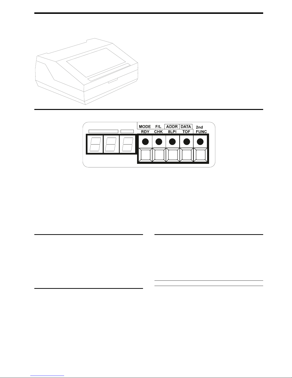
Control Panel
Buttons/Keys
RDY/MODE: Places printer online or offline.
CHK-F/L: Clears fault status after minor malfunction, i.e., jammed paper/ribbon,
out of paper, and forms thickness.
8LPI/ADDR: Changes to alternate line spacing, i.e., 6 lpi (default), 8 lpi, or 10
lpi.
TOF/DATA: Advances paper to TOP-OF-FORM or single line feed. (Press and
hold for TOF and press and release for LF).
2nd FUNC: Secondary Function: Allows the previous four switches to have
alternate functions, i.e., RDY becomes a printer mode switch, CHK becomes a
forms length switch, 8LPI becomes a printer configuration address change switch
(ADDR) in the numeric display LED, and TOF becomes a DATA switch to select
one of nine option for configuration address changing.
Note:
See “Configuration” for more details on how to use this switch.
Self-test
1. Lift the printer cover. Ensure that the RDY indicator is flashing.
2. Press the 2nd FUNC switch (inside the printer).
3. Press the ADDR switch; the indicator will stay on steadily. A code on the
digital panel (under the red stripe) will show two digits. If this is the first use
of the ADDR switch after the power has been turned on, 00 will show; otherwise the last code will display:
00.1 Prints the printer's configuration.
00.2 Prints the style of character set ordered for the printer.
01.1 Prints 8 tests which include the alphabet, underlines, and individual
02.1 Prints the letter "E" continuously.
03.1 Prints a rotating alphabet.
letters.
Cover Removal
Upper and Rear Covers
1. Turn power off and unplug the printer from the wall socket.
2. Lift the upper cover up and lock it into place using the hinge lock mechanism.
3. Unscrew the top cover from the hinge brackets and carefully lift up and set the
cover to the side.
4. Lower the back cover, then swing the open card cage which is held by a magnetic latch at its right hand end.
5. All internal parts are now accessible to the printer.
LEDs/Lights
RDY: When lit, indicates printer is online. When flashing, indicates printer is
offline.
CHK: Flashing = minor error and steady = service required.
When lit, indicates service is required. When flashing, indicates a minor error.
8LPI: When on, indicates alternate line spacing has been chosen. When off, indi-
cates 6 lpi (default).
TOF: When on, indicates TOF has been set.
2nd FUNC: When on, indicates secondary function choice has been selected for
the RDY, CHK, 8LPI, and TOF switches. When off, indicates standard function for
these switches has been selected.
DISPLAY: A three-digit display used to show configuration choices and five (5)
operator error codes.
Configuration
The MVP 150 Printronix printer uses a combination of keys, i.e., the 2nd FUNC,
ADDR, DATA and RDY to set up the configuration which are displayed as
addresses on the numeric display at the left of the operator's control panel. The
entire three-digit configuration display is in the form XX.Y where:
XX = The two left digits from 00 to 99 and .Y = the third digit from .0 to .9
Note:
Addresses 00-19 are test and service printout addresses. Addresses 20-99
are configuration addresses. Table 1 is the procedure to change configurations,
and Table 2 on page 2 are the default settings:
Table 1 (Page 1 of 2). Release Configuration Safety Lockout
Action Result
1. Press & release RDY switch. Indicator is flashing.
2. Press & release 2nd FUNC switch. Indicator is on.
3. Press & hold ADDR until display
reads 16.0.
4. Press & release DATA until display
reads 16.3.
5. Press & release 2nd FUNC. Printer returns to offline. RDY is
NOTE: Repeat steps 6-11 for each configuration change desired. When completed, continue at step 12.
6. Press & release 2nd FUNC. Indicator is On.
7. Press & release ADDR. Indicator is On. Display shows current
8. Press & release ADDR. Address advances by 01.
Display reads 16.
Display reads 16.3.
flashing. All other indicators are off.
Enables reconfiguration.
address and configuration number.
96-04-30 Copyright IBM Corporation 1995.
All rights reserved. PR-1 1
Page 2

Printronix MVP 150 OSR
Table 1 (Page 2 of 2). Release Configuration Safety Lockout Table 2 (Page 1 of 2). Configuration Numbers and Options
Action Result Config
OR
Press & hold ADDR. Address advances continuously;
9. Press & hold DATA. Enables DATA function for selecting the
10. Press & release DATA. Display advances by .1. Press & release
11. Press & release 2nd FUNC key. Puts new option number into printer
12. Press & hold ADDR until 16.3 is in
display.
13. Press & release DATA until display
reads 16.4.
14. Press & release 2nd FUNC. Printer returns to offline mode. New
Table 2 (Page 1 of 2). Configuration Numbers and Options
Config
Option
Number
(ADDR)
20 Expanded print select
21 Must be set to 21.0
22 Insert auto LF in data stream
23 Automatic LF on CR
Display Configuration Description
Number
(DATA)
.0 20.0 Double wide on per line basis only. Enables mode 6.
.1 20.1 Per character with doubling through control codes
.0 22.0 Disble auto LF insert (default)
.1 22.1 132 X X
.2 22.2 104 X X
.3 22.3 80 X X
.4 22.4 80 XXXX
.0 23.0 CR=0 line feed (default)
.1* 23.1 CR=1 line feed
.2* 23.2 CR=2 line feeds
.3* 23.3 CR=3 line feeds *
(Modes 1-5)(default). Disables mode 6.
Insert LF at character:
CHARACTER MODE
default 165 X
220 X
66 X
132 X
176 X
52 X
100 X
132 X
40 X
40 X
Note: Use of option number 1,2, and 3 requires
24 Must be set to 24.0
25 Must be set to 25.0
26 Printer on-line with power on.
.0 26.0 Disable
.1 26.1 Enable (default).
27
24 Must be set to 24.0
25 Must be set to 25.0
26 Printer on-line with power on.
.0 26.0 Disable
.1 26.1 Enable (default).
27 paper out delay
.0 27.0 Print current line only (default).
.1 27.1 Print to
28 Automatic underlining (ESC, -;n)
.0 28.0 Suppresses underlining on lead/trial spaces (default).
1 28.1 Print to end of form.
29** DEL character options.
.0 29.0 DEL character interpreted as space(or character in
.1 29.1 DEL character deletes previous character sent.
.2 29.2 Ignore DEL character. **NOTE: This configuration
30 Application mode at power-on.
.0 30.0 Enable data processing mode (default).
.1 30.1 Enable word processing mode.
end of
form
position 127)
available only on printers equipped with V50.59 DCU &
MCU 20.25 (or later) firmware & primary font PROM
116043-001 or equivalent.
Release ADDR to stop. .2 30.2 Enable compressed print mode (12.5 cpi, high speed).
third digit.
DATA key until desired option number is
showing in the third digit of the display.
memory.
Display reads 16.3. .0 32.0 Extended character address 128 produces a space.
Display reads 16.4. Locks out accidental
reconfiguration.
configuration is locked in.
12356
that underlining be performeed using either
BS or ESC,-;n. (SEE also configuration
option 28.1).
Option
Number
(ADDR)
31 Control code.
32* Cedilla character select.
33 Must be set to 33.0
34 Alternate printronix plot control sequence.
35 Alternate printronix plot control sequence
36 Mode 1 select.
37 Mode 2 select
38 Double high select
39 Mode 3 select.
40 Additional print characters
41* Extended character set select
42 Must be set to 42.0
43 raster plot exit
44 through 49 not used
50 page perforation skip
51 Lines per inch (line spacing).
52 Forms length at printer power-up.
53 through 55 not used
56* Character columns select
57 through 59 not used
60 Use of dataline 8 with parallel interface.
61 through 66 must be set to there respective number with a .0 decimal
Display Configuration Description
Number
(DATA)
.3 30.3 Enable high-speed plot mode.
.4 30.4 Enable condensed print mode (16.7 cpi).
.5 30.5 Enable double wide character (5 cpi).
.0 31.0 Enable ESC l, !, P, R (default)
.1 31.1 Enable ESC h, , n, r.
.1 32.1 Extended character address 128 produces the cedilla
.0 34.0 Enable ESC Y, even dot centers (default)
.1 34.1 Ignore ESC Y.
.0 35.0 enable ESC Z, odd dot centers (default).
.1 35.1 Ignore ESC Z.
.0 36.0 Enable ESC P = Mode 1 (default)(ESC n if config 31.1)
.0 37.0 Enable ESC R = Mode 2 (default)(ESC r if config 31.1)
.1 37.1 Ignore ESC l.
.0 38.0 Enable ESC l = double high (default)(ESC h if config
.1 38.1 Ignore ESC l.
.0 39.0 Enable ESC V = Mode 3 (default)
.1 39.1 Ignore ESC V.
.0 40.0 Characters 03, 04, 05, 06 and 21 interpreted as control
.1 40.1 Add printable characters for decimal addresses 03, 04,
.1 41.1 Characters 128-160 selected at printer power-up (ESC
.0 43.0 Single line terminator moves print head to next dot
.1 43.1 Line terminator moves print head to the top of the next
.0 50.0 Skip 3 lines.
.1 50.1 No skip (default).
.2 50.2 Skip 4 lines.
.3 50.3 Skip 5 lines.
.4 50.4 Skip 6 lines.
.0 51.0 Enable 6 & 8 lpi (default)
.1 51.1 Enable 6 & 9 lpi (activated from front panel only).
.2 51.2 Enable 6 & 10 lpi.
.0 52.0 Enables 11 inches (default).
.1 52.1 Enables 3.5 inches.
.2 52.2 Enables 5.5 inches.
.3 52.3 Enables 7 inches.
.4 52.4 Enables 8.5 inches.
.5 52.5 Enables 12 inches.
.6 52.6 Enables 14 inches.
.7 52.7 Enables F/L switch setting; F/l switch setting retained
.0 56.0 132 character columns (default).
.1 56.1 136 character columns. NOTE: See note from 31.
.0 60.0 Disable data line 8.
.1 60.1 Enable data line 8 (allows access to characters
character (default). *NOTE: This configuration available only on V50.59 DCU, MCU 20.25 (or later)
firmware, and primary font PROM 116043-001 or
equivalent.
31.1)
characters (default)
05, 06 and 21 (ESC 6 select).
6 and ESC 7 ignored). NOTE: See note from 31.
row. Additional line terminator moves print head to top
of next character line. Maintains line registration within
the page (default).
character dot row. No extra line terminator needed to
avoid truncating any following character printing.
when power is cycled OFF.
128-255).
2 PR-1 IBM/TSS Internal Use Only
Page 3

OSR Printronix MVP 150
Table 2 (Page 2 of 2). Configuration Numbers and Options
Config
Option
Number
(ADDR)
67 through 99 not used
Display Configuration Description Cable Asm 1/0 Par 110376-002 45F4315
Number
(DATA)
Error Codes
011 Load paper.
012 Return the forms thickness lever to a correct position or check that the
013 Check that the paper is feeding correctly.
014 Remove jammed paper or straighten the ribbon.
015 Remove jammed paper, straighten the ribbon or check the forms thick-
black plastic cover may be out of place.
ness lever.
Operator Procedures
Ribbon Installation
1. Lift the print cover - the power does not need to be on when the ribbon is
loaded, but if it is, ensure that the RDY light is flashing.
2. Move the forms thickness lever (right side of printer) as far as it will go toward
the back of the printer. The two metal strips (ribbon mask) in back of the ruler
will separate slightly.
3. Place one spool of ribbon on a hub so that the locking latch snaps into place
and the ribbon unwinds toward the outside.
4. Pass the ribbon around the ribbon guides and carefully place the ribbon
between the two strips of metal. Ensure that the ribbon is not twisted.
5. Place the second spool of ribbon on a hub so that the locking latch snaps into
place and the ribbon winds toward the inside. Adjust the ribbon's tautness by
hand winding the spool.
6. Adjust the forms thickness lever to a position that is correct for the thickness
of the paper.
7. If the power had been on, press the CHK switch; however, the CHK indicator
will continue to flash if no paper is in the printer.
Loading Paper
1. Lift the printer cover - the power does not need to be on when loading the
paper, but if it is, ensure the RDY indicator is flashing.
2. Move the forms thickness lever as far as the lever will go toward the back of
the printer.
3. Pull the right tractor lever down to unlock, then open both tractor gates. You
can unlock the left tractor lever too, however, if you keep the left tractor stationary, you will have less to adjust later.
4. Feed paper into the slot - underneath if the printer is pedestal mounted or at
the front if you have a front feed attachment. Continue to feed the paper until
it passes between the metal strips and the wide metal bar.
5. Load paper on the left tractor sprocket pins and close the tractor gate. Load
paper on the right tractor sprocket pin. Make sure that the paper is aligned
horizontally. Close the right tractor gate.
6. If the left tractor was kept stationary, go to paragraph 7, and if not, slide both
tractors so that the edge of the paper lines up with the first mark on the printer's ruler, or where you want the left margin to print. Lock the left tractor
lever.
7. Adjust the right tractor so that the paper has just enough tension to be fault
and taut without pulling. Pull the right tractor lever up to lock it.
8. Advance the paper with the positioning knob (platen) so that the paper will
feed out the opening between the raised cover and the top of the printer.
Ensure that the paper supply from the bottom will feed into the printer in a
straight line.
9. Adjust the forms thickness lever to a position that is correct for the thickness
of the paper.
10. If the power had been on, press the CHK switch. If the power had been off,
turn the power on; press and release the RDY switch.
11. Set the top of form (TOF).
Description OEM P/N IBM P/N
Encoder 110487-901 45F4316
Encoder Linear 110159-001 45F4317
Hammer Bank Cable Assm 110599-001 45F4318
Hammer Bank Cover Assm 110218-001 45F4319
Service Documentation
There is no service documentation available to be ordered at this time.
Common Problem and fixes
CHK Indicator Action
Flashing 011 No paper Load paper
Flashing 012 Forms thickness lever open;
Flashing 014 Shuttle jam; remove any
Fault
Fault Corrective Description
Code
shuttle assembly cover off or
out of place.
jammed paper, straighten
ribbon, or check forms thickness lever.
Printer Options
Front feed paper guide
Printer pedestal and paper basket
Field Replaceable Units (FRU's)
96-04-30 Copyright IBM Corporation 1995.
All rights reserved. PR-1 3
Close lever; replace or reseat
shuttle cover.
Page 4

Printronix MVP 150 OSR
4 PR-1 IBM/TSS Internal Use Only
Page 5

OSR Printronix MVP 150
IBM machine type: 1003-XXX
Tech Support 800-877-7764
96-04-30 Copyright IBM Corporation 1995.
All rights reserved. PR-1 5
 Loading...