

Page 1
R
MVP Series
User's Manual
Page 2

Page 3

MVP Series
User's Manual
P/N 112301–001, Rev B
R
Page 4

US and CANADA Radio Interference Note
Note: This device complies with Part 15 of the FCC Rules. Operation is subject to the following two
conditions: (1) this device may not cause harmful interference, and (2) this device must accept any
interference received, including interference that may cause undesired operation.
Properly shielded and grounded cables and connectors must be used in order to meet FCC emission limits.
The manufacturer is not responsible for any radio or television interference caused by using other than
recommended cables and connectors or by unauthorized changes or modifications to this equipment.
Unauthorized changes or modifications could void the user’s authority to operate the equipment.
The input/output (I/O) cable must be shielded for the printer to comply with FCC rules and regulations Part
15 governing the radiation limits for Class “A” equipment.
This Class A digital apparatus meets all requirements of the Canadian Interference–Causing Equipment
Regulations.
Cet appareil numérique de la classe A respecte toutes les exigences du Règlement sur le matériel brouilleur
du Canada.
WARNING
This is a Class A product. In a domestic environment this product may cause radio interference in which
case the user may be required to take adequate measures.
Printronix, Inc. makes no representations or warranties of any kind regarding this material, including, but not
limited to, implied warranties of merchantability and fitness for a particular purpose. Printronix, Inc. shall not
be held responsible for errors contained herein or any omissions from this material or for any damages,
whether direct, indirect, incidental or consequential, in connection with the furnishing, distribution,
performance or use of this material. The information in this manual is subject to change without notice.
This document contains proprietary information protected by copyright. No part of this document may be
reproduced, copied, translated or incorporated in any other material in any form or by any means, whether
manual, graphic, electronic, mechanical or otherwise, without the prior written consent of Printronix, Inc.
All rights reserved. Revision B. March, 1996.
TRADEMARK ACKNOWLEDGMENTS
Printronix is a registered trademark of Printronix, Inc.
MVP is a registered trademark of Printronix, Inc.
IGP is a registered trademark of Printronix, Inc.
17500 Cartwright Road, P.O. Box 19559
Irvine, California 92713
Telephone (714) 863–1900 FAX (714) 660–8682
Technical Support (714) 221–2686
COPYRIGHT 1991, 1996, PRINTRONIX, INC.
Page 5

Table of Contents
1
Introduction
About This Manual 1–2. . . . . . . . . . . . . . . . . . . . . . . . . . . . . . . . . . . . . . . . . . . .
Introduction 1–4. . . . . . . . . . . . . . . . . . . . . . . . . . . . . . . . . . . . . . . . . . . . . . . . . .
Printer Features 1–4. . . . . . . . . . . . . . . . . . . . . . . . . . . . . . . . . . . . . . . . . . . . . . .
MVP–Series Printers 1–5. . . . . . . . . . . . . . . . . . . . . . . . . . . . . . . . . . . . . . . .
L150 Printers 1–6. . . . . . . . . . . . . . . . . . . . . . . . . . . . . . . . . . . . . . . . . . . . . .
150B/L150B Printers 1–6. . . . . . . . . . . . . . . . . . . . . . . . . . . . . . . . . . . . . . . .
Optional Features 1–7. . . . . . . . . . . . . . . . . . . . . . . . . . . . . . . . . . . . . . . . . . .
Character Formation 1–8. . . . . . . . . . . . . . . . . . . . . . . . . . . . . . . . . . . . . . . . . . . .
Line Matrix Printing 1–9. . . . . . . . . . . . . . . . . . . . . . . . . . . . . . . . . . . . . . . . . . . .
Print Rate 1–10. . . . . . . . . . . . . . . . . . . . . . . . . . . . . . . . . . . . . . . . . . . . . . . . . . .
Plot Rate 1–11. . . . . . . . . . . . . . . . . . . . . . . . . . . . . . . . . . . . . . . . . . . . . . . . . . . .
2 Installation
Introduction 2–2. . . . . . . . . . . . . . . . . . . . . . . . . . . . . . . . . . . . . . . . . . . . . . . . . .
Power Requirements 2–3. . . . . . . . . . . . . . . . . . . . . . . . . . . . . . . . . . . . . . . . . . .
Site Requirements 2–4. . . . . . . . . . . . . . . . . . . . . . . . . . . . . . . . . . . . . . . . . . . . .
Installing the Printer 2–5. . . . . . . . . . . . . . . . . . . . . . . . . . . . . . . . . . . . . . . . . . . .
Assembling the Pedestal 2–5. . . . . . . . . . . . . . . . . . . . . . . . . . . . . . . . . . . . .
Assembling the Paper Tray 2–8. . . . . . . . . . . . . . . . . . . . . . . . . . . . . . . . . . .
Mounting the Printer onto the Pedestal 2–9. . . . . . . . . . . . . . . . . . . . . . . . . .
Attaching the Paper Tray 2–10. . . . . . . . . . . . . . . . . . . . . . . . . . . . . . . . . . . .
Table Top Mounting 2–11. . . . . . . . . . . . . . . . . . . . . . . . . . . . . . . . . . . . . . .
Applying Power 2–12. . . . . . . . . . . . . . . . . . . . . . . . . . . . . . . . . . . . . . . . . . .
Preliminary Testing 2–12. . . . . . . . . . . . . . . . . . . . . . . . . . . . . . . . . . . . . . . . . . .
i
Page 6

3 Operation
Introduction 3–2. . . . . . . . . . . . . . . . . . . . . . . . . . . . . . . . . . . . . . . . . . . . . . . . . .
Mechanical Controls 3–2. . . . . . . . . . . . . . . . . . . . . . . . . . . . . . . . . . . . . . . . . . .
Power On–Off 3–3. . . . . . . . . . . . . . . . . . . . . . . . . . . . . . . . . . . . . . . . . . . . .
Operator Panel Switches and Indicators 3–3. . . . . . . . . . . . . . . . . . . . . . . . .
Second Function Switches 3–6. . . . . . . . . . . . . . . . . . . . . . . . . . . . . . . . . . . .
Loading Ribbon 3–8. . . . . . . . . . . . . . . . . . . . . . . . . . . . . . . . . . . . . . . . . . . . . . .
Removing the Ribbon 3–10. . . . . . . . . . . . . . . . . . . . . . . . . . . . . . . . . . . . . .
Paper Guidelines 3–11. . . . . . . . . . . . . . . . . . . . . . . . . . . . . . . . . . . . . . . . . . . . .
Paper Type and Thickness 3–11. . . . . . . . . . . . . . . . . . . . . . . . . . . . . . . . . . .
Loading Paper 3–12. . . . . . . . . . . . . . . . . . . . . . . . . . . . . . . . . . . . . . . . . . . . . . .
Removing Paper 3–15. . . . . . . . . . . . . . . . . . . . . . . . . . . . . . . . . . . . . . . . . .
Setting Top–of–Form 3–16. . . . . . . . . . . . . . . . . . . . . . . . . . . . . . . . . . . . . . . . . .
Setting Forms Length 3–17. . . . . . . . . . . . . . . . . . . . . . . . . . . . . . . . . . . . . . . . . .
4 Configuration
Introduction 4–2. . . . . . . . . . . . . . . . . . . . . . . . . . . . . . . . . . . . . . . . . . . . . . . . . .
Changing Configurations 4–3. . . . . . . . . . . . . . . . . . . . . . . . . . . . . . . . . . . . . . . .
MVP/L150 4–3. . . . . . . . . . . . . . . . . . . . . . . . . . . . . . . . . . . . . . . . . . . . . . .
150B /L150B 4–4. . . . . . . . . . . . . . . . . . . . . . . . . . . . . . . . . . . . . . . . . . . . .
Verifying Configurations 4–5. . . . . . . . . . . . . . . . . . . . . . . . . . . . . . . . . . . . . . . .
Configuration Options 4–6. . . . . . . . . . . . . . . . . . . . . . . . . . . . . . . . . . . . . . . . . .
Quick Reference Table for Configuration Options 20–61 4–7. . . . . . . . . . . .
ii
Page 7

5 Graphics
Introduction 5–2. . . . . . . . . . . . . . . . . . . . . . . . . . . . . . . . . . . . . . . . . . . . . . . . . .
Raster Plotting 5–2. . . . . . . . . . . . . . . . . . . . . . . . . . . . . . . . . . . . . . . . . . . . . . . .
Raster Plot Syntax 5–4. . . . . . . . . . . . . . . . . . . . . . . . . . . . . . . . . . . . . . . . .
Print Modes for Raster Plots 5–5. . . . . . . . . . . . . . . . . . . . . . . . . . . . . . . . . .
High Resolution Raster Plot Syntax 5–6. . . . . . . . . . . . . . . . . . . . . . . . . . . .
Scaling Graphics 5–6. . . . . . . . . . . . . . . . . . . . . . . . . . . . . . . . . . . . . . . . . . .
Exiting from Raster Plot 5–7. . . . . . . . . . . . . . . . . . . . . . . . . . . . . . . . . . . . .
Bit Image Graphics 5–8. . . . . . . . . . . . . . . . . . . . . . . . . . . . . . . . . . . . . . . . . . . .
Characteristics of Bit Image Graphics 5–8. . . . . . . . . . . . . . . . . . . . . . . . . .
Plotting a Bit Image Pattern 5–10. . . . . . . . . . . . . . . . . . . . . . . . . . . . . . . . .
Bit Image Density 5–11. . . . . . . . . . . . . . . . . . . . . . . . . . . . . . . . . . . . . . . . .
Bit Image Programming Format 5–12. . . . . . . . . . . . . . . . . . . . . . . . . . . . .
Bit Image Sample Program 5–13. . . . . . . . . . . . . . . . . . . . . . . . . . . . . . . . .
Other Bit Image Features 5–14. . . . . . . . . . . . . . . . . . . . . . . . . . . . . . . . . . .
P–Series Plot Mode 5–15. . . . . . . . . . . . . . . . . . . . . . . . . . . . . . . . . . . . . . . . . . .
Plot Density 5–15. . . . . . . . . . . . . . . . . . . . . . . . . . . . . . . . . . . . . . . . . . . . . .
Plot Data Byte Format 5–16. . . . . . . . . . . . . . . . . . . . . . . . . . . . . . . . . . . . .
Plot Data Line Format 5–18. . . . . . . . . . . . . . . . . . . . . . . . . . . . . . . . . . . . .
Plotting Data 5–20. . . . . . . . . . . . . . . . . . . . . . . . . . . . . . . . . . . . . . . . . . . . .
Exiting P–Series Plot Mode 5–22. . . . . . . . . . . . . . . . . . . . . . . . . . . . . . . . .
iii
Page 8

6 EFVU
Introduction 6–2. . . . . . . . . . . . . . . . . . . . . . . . . . . . . . . . . . . . . . . . . . . . . . . . . .
Programming EVFU Memory 6–2. . . . . . . . . . . . . . . . . . . . . . . . . . . . . . . . . . . .
Using EVFU 6–8. . . . . . . . . . . . . . . . . . . . . . . . . . . . . . . . . . . . . . . . . . . . . . . . . .
EVFU/IGP Execute Form Mode 6–9. . . . . . . . . . . . . . . . . . . . . . . . . . . . . . . . . .
Relative Line Slewing 6–9. . . . . . . . . . . . . . . . . . . . . . . . . . . . . . . . . . . . . . . . . .
Clearing EVFU Memory 6–11. . . . . . . . . . . . . . . . . . . . . . . . . . . . . . . . . . . . . . .
Start Load Code — 6Hex 6–2. . . . . . . . . . . . . . . . . . . . . . . . . . . . . . . . . . . .
Channel Assignment 6–3. . . . . . . . . . . . . . . . . . . . . . . . . . . . . . . . . . . . . . .
End Load Code — 6F Hex 6–4. . . . . . . . . . . . . . . . . . . . . . . . . . . . . . . . . .
EVFU Command Codes 6–5. . . . . . . . . . . . . . . . . . . . . . . . . . . . . . . . . . . . .
EVFU Programming Example 6–5. . . . . . . . . . . . . . . . . . . . . . . . . . . . . . .
Troubleshooting for EVFU Programming 6–7. . . . . . . . . . . . . . . . . . . . . . . .
7 Programming
Introduction 7–2. . . . . . . . . . . . . . . . . . . . . . . . . . . . . . . . . . . . . . . . . . . . . . . . . .
Control Codes (Quick Reference Tables) 7–3. . . . . . . . . . . . . . . . . . . . . . . . . . .
MVP/L150 Control Codes 7–4. . . . . . . . . . . . . . . . . . . . . . . . . . . . . . . . . . . . . . .
150B/ L150B Control Codes 7–27. . . . . . . . . . . . . . . . . . . . . . . . . . . . . . . . . . . .
8 Interface
Introduction 8–2. . . . . . . . . . . . . . . . . . . . . . . . . . . . . . . . . . . . . . . . . . . . . . . . . .
Centronics and Dataproducts Interface Characteristics 8–2. . . . . . . . . . . . . .
Centronics Interface 8–3. . . . . . . . . . . . . . . . . . . . . . . . . . . . . . . . . . . . . . . . . . . .
Dataproducts Interface 8–5. . . . . . . . . . . . . . . . . . . . . . . . . . . . . . . . . . . . . . . . . .
Interface Configuration Options 60–99 8–8. . . . . . . . . . . . . . . . . . . . . . . . . . . . .
Switching Interfaces 8–26. . . . . . . . . . . . . . . . . . . . . . . . . . . . . . . . . . . . . . . . . . .
iv
Page 9

9 Routine Service and Diagnostics
Introduction 9–2. . . . . . . . . . . . . . . . . . . . . . . . . . . . . . . . . . . . . . . . . . . . . . . . . .
Cleaning Requirements 9–2. . . . . . . . . . . . . . . . . . . . . . . . . . . . . . . . . . . . . . . . .
Before Cleaning 9–3. . . . . . . . . . . . . . . . . . . . . . . . . . . . . . . . . . . . . . . . . . . .
Cleaning the Printer 9–5. . . . . . . . . . . . . . . . . . . . . . . . . . . . . . . . . . . . . . . . .
Moving the Printer 9–7. . . . . . . . . . . . . . . . . . . . . . . . . . . . . . . . . . . . . . . . . .
Reconnecting the Cables 9–8. . . . . . . . . . . . . . . . . . . . . . . . . . . . . . . . . . . . .
Corrective Maintenance 9–9. . . . . . . . . . . . . . . . . . . . . . . . . . . . . . . . . . . . . . . . .
Self–Tests 9–10. . . . . . . . . . . . . . . . . . . . . . . . . . . . . . . . . . . . . . . . . . . . . . . . . . .
Self–Test Procedure 9–10. . . . . . . . . . . . . . . . . . . . . . . . . . . . . . . . . . . . . . .
Self–Test Configuration 9–12. . . . . . . . . . . . . . . . . . . . . . . . . . . . . . . . . . . .
Appendices
Appendix A: Character Sets and Control Codes
Index
Appendix B: Printer Diagnosics
Appendix C: Specifications, Accessories and Options
v
Page 10

vi
Page 11

1 Introduction
Chapter Contents
About This Manual 1–2. . . . . . . . . . . . . . . . . . . . . . . . . . . . . . . . . . . . . . . . . . . .
Introduction 1–4. . . . . . . . . . . . . . . . . . . . . . . . . . . . . . . . . . . . . . . . . . . . . . . . . .
Printer Features 1–4. . . . . . . . . . . . . . . . . . . . . . . . . . . . . . . . . . . . . . . . . . . . . . .
MVP–Series Printers 1–5. . . . . . . . . . . . . . . . . . . . . . . . . . . . . . . . . . . . . . . .
L150 Printers 1–6. . . . . . . . . . . . . . . . . . . . . . . . . . . . . . . . . . . . . . . . . . . . . .
150B/L150B Printers 1–6. . . . . . . . . . . . . . . . . . . . . . . . . . . . . . . . . . . . . . . .
Optional Features 1–7. . . . . . . . . . . . . . . . . . . . . . . . . . . . . . . . . . . . . . . . . . .
Character Formation 1–8. . . . . . . . . . . . . . . . . . . . . . . . . . . . . . . . . . . . . . . . . . . .
Line Matrix Printing 1–9. . . . . . . . . . . . . . . . . . . . . . . . . . . . . . . . . . . . . . . . . . . .
Print Rate 1–10. . . . . . . . . . . . . . . . . . . . . . . . . . . . . . . . . . . . . . . . . . . . . . . . . . .
Plot Rate 1–11. . . . . . . . . . . . . . . . . . . . . . . . . . . . . . . . . . . . . . . . . . . . . . . . . . . .
Overview 1–1
Page 12

About This Manual
This manual applies to the MVP–Series of Printronix printers; the standard
MVP, L150, 150B and L150B. Explanations and descriptions that refer to
standard MVP or MVP–Series printers apply to all four printers in the series.
Chapters that address configuring and programming issues distinguish
between the MVP/L150 and 150B/L150B. This is due to the different
software pertaining to each printer. In all other areas, the four printer are
similar.
How to Locate Information
• Use the Table of Contents at the front of the manual.
• Use the Chapter Contents listed on the first page of each chapter.
• Use the Index at the back of the manual.
Warnings and Special Information
Read and comply with all information highlighted under special headings:
WARNING
Conditions that could harm you as well as damage the equipment.
CAUTION
Conditions that could damage the printer or related equipment.
IMPORTANT
Information vital to proper operation of the printer.
NOTE: Information affecting printer operation.
Overview1–2
Page 13

Switches, Keys, Indicators and Display Messages
Switches, indicators and switch positions on the printer are uppercase. For
example: Press and release the RDY switch.
Messages that appear on the control panel display are printed in initial capital
letters and set off with quotation marks (except for conjunctions, which are
all lowercase). For example: “Save Config” appears on the message display.
Overview 1–3
Page 14

Introduction
The MVP–Series printers are line matrix printers that provide high quality
printing and graphics by printing at 200 lines–per–minute (lpm) and plotting
at 18.7 lpm in five different print modes. They offer features such as dot
matrix flexibility, plug–in PROMs that allow alternate character sets to
substitute for the standard set and the capability of printing on a wide variety
of multi–part forms, labels and other business forms.
All MVP–Series printers have a digital panel and switches that allow you to
select and control internal functions, run self–tests, and configure the printer
for selected responses to commands and data from the host computer.
Printer Features
The Standard MVP is a sophisticated printer that has a wide variety of
printing capabilities. It provides standard features and functions that allow
you to control and define printer output. Its counterpart, the L150, offers the
Standard MVP features and functions along with additional features that
allow for especially high quality print and graphics. The 150B and L150B
not only offer all of the Standard MVP and L150 functions and features, but
they are also designed to meet the specifications of industry bar code
standards for the Department of Defense (LOGMARS), Auto Industry
(AIAG), Health Industry (HIBC), and others.
Overview1–4
Page 15

MVP–Series Printers
All MVP printers offer these standard features:
• Alternate character sets
• Electronic Vertical Format Unit
• Elongated characters
• Test pattern printing
• Host mode control
• Plotting
• Slewing
• Underlining
• Accommodating a wide variety of forms, including card stock, adhesive
backed forms for label applications, and one–part to six–part bond for
reports.
In the normal operating mode, all MVP printers provide the following
standard functions at the control panel:
• Placing the printer on–line or off–line
• Changing spacing selection
• Controlling paper advance
• Displaying the current printer operating mode (1–5)
• Displaying a status condition with a displayed fault code
• Displaying the selected line spacing
In the normal operating mode, all MVP printers provide the following
standard functions from the host:
• Changing the print mode
• Changing the forms length
• Configuring the printer
• Running self–tests
• Configuring with a Printronix Intelligent Graphics Processor (IGP–20)
to produce bar codes, labels, and business forms.
Overview 1–5
Page 16

L150 Printers
In addition to the standard features and functions listed in “MVP Printers,”
the L150 printers print approximately a 0.017 inch diameter dot that assures
printed bar codes will meet demanding size and quality specifications. L150
printers also have various print modes that match dot density and resolution
to specific bar code applications:
• MODE 2 prints text at a character pitch of 10 cpi for data processing
applications.
• MODE 4 provides a plot density designed for bar codes such as Code
3/9, Interleaved 2/5, and Code 128. In addition, text can be printed at a
character pitch of 12.1 cpi.
• MODE 5 provides a plot density designed for Universal Product Code
(UPC) and European Article Numbering (EAN) bar codes. In addition,
text can be printed at a character pitch of 13.3 cpi.
150B/L150B Printers
In addition to the standard features and functions listed in “MVP Printers,”
the 150B/L150B printers offer a configuration lock and unlock feature.
Special to the 150B and L150B is a raster dot matrix code configured in a
character format, which allows multi–mode character printing. These dot
matrix codes are accessed by an ASCII character code transmitted by the
computer. The flexibility of the dot matrix code structure permits the
configuration of a wide variety of characters and symbols for international
languages and graphic applications. The 150B/ L150B multi–density
graphics capabilities include plots, bar codes, graphs, block printing, and
complex curves.
Overview1–6
Page 17

Optional Features
The following are some of the various optional features offered to extend the
versatility of MVP–Series printers:
Special and Custom Character Sets
96 character ASCII; 64 character, OCR full width; EBCDIC; Block
characters; and Custom characters.
Standard MVP Density Option
Permits a four percent increase in MVP vertical dot density.
Long Lines Interface
Enables operation with a Dataproducts 2230 or 2260, differential drive,
balanced interface type controller. The interface can transfer up to 400,000
characters per second for distances up to 500 feet.
PI–3287 Printer Interface
Allows the L150 to emulate an IBM 3287 printer, and attaches to IBM 3274
or 3276 cluster controllers through Type A Interface. It may be used with or
without IGP–20 option.
IGP–20
The IGP–20 makes it easy to define, store, and then print forms and labels in
a single pass. Functions that can be performed with the IGP–20 are:
• On–line Forms Generation - boxes, corners, vertical and horizontal
lines, logos and special form size print can be generated for a preprinted
appearance.
• Variable Bar Codes - size, rotation, and bar code data fields are easy to
define and print.
• Expanded characters - characters can be created up to 99 times larger
than normal for labels, titles, and signs. The vertical and horizontal sizes
of characters are controlled independently to create different
appearances.
• Logos - expanded characters and reverse print can combine with
graphics to create customized logos. Up to 16 logos may be stored, then
called from a library for printing, either individually or in combination
with the create forms mode.
• Compressed Print– allows up to 132 characters printed on one line of
standard 8 1/2 inch wide paper.
• Reverse Print - allows printing reversed to white on black .
Overview 1–7
Page 18

Character Formation
The MVP–Series printers generate characters by accumulating groups of dots
in matrices. Dot impressions are made by an assembly of 17 hammers
installed on an oscillating shuttle that impact the paper through a moving ink
ribbon. Synchronized horizontal shuttle movement and vertical paper
advancement produce overlapping dots that form solid characters
(Figure 1–1).
Figure 1–1. Typical Character Formation
Overview1–8
Page 19
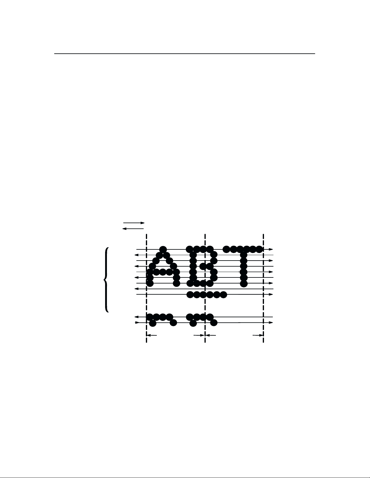
Line Matrix Printing
Unlike moving–head serial dot matrix printers, the MVP–Series printers
create graphics and characters by printing an entire dot row at one time. Dots
are printed in both directions of shuttle travel, at a printer stroke length of .2”
to print through two character positions. By printing a row of dots, dot matrix
line printers achieve higher print duty cycles than moving head dot matrix
(serial) printers.
During each sweep of the shuttle, hammers are activated to print dots at
selected positions in that dot row. When the shuttle reaches the end of a
sweep, it reverses direction, paper advances one dot row, and the hammers
print the next consecutive row of dots.
After a line of characters is printed, hammer print action ceases while the
paper advances to the first dot row of the next print line. The number of rows
allowed for line separation depends on the line spacing selected.
ONE
CHARACTER
ROW
DIRECTION OF SHUTTLE MOVEMENT
DOT
ROW START
1
2
3
4
5
6
7
8
*
9
**
10
11
SPACE
12
1
2
1 HAMMER
PRINT SPAN
**
USED FOR LOWERCASE DESCENDER ONLY
*
USED FOR UNDERLINE AND LOWERCASE DESCENDER
**
Figure 1–2. Line Matrix Printing
1 HAMMER
PRINT SPAN
PAPER
ADVANCES
PAPER
FEED
PAPER
ADVANCES
Overview 1–9
Page 20
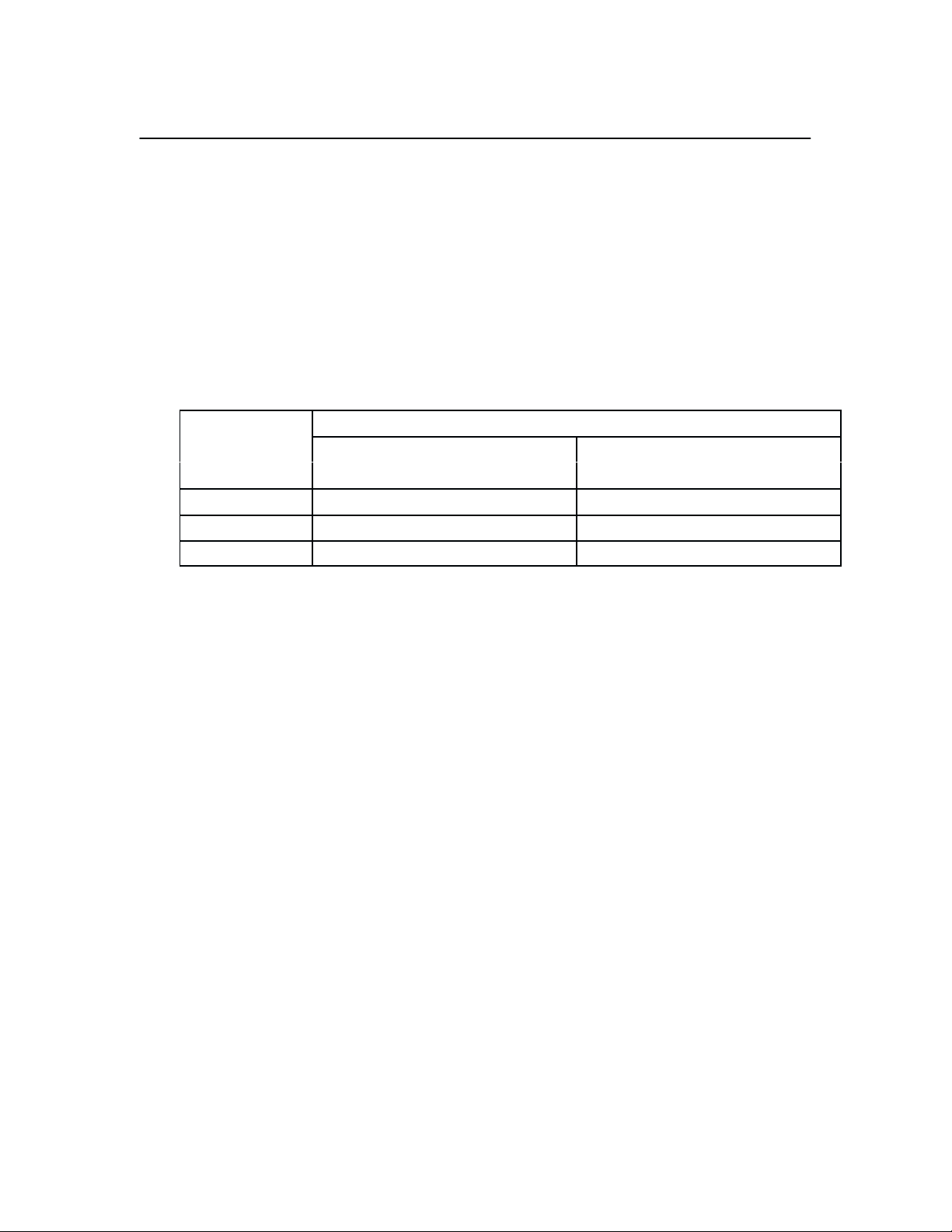
Print Rate
The print rate, in lines per minute (lpm), is a function of the number of dot
rows required to produce the character line regardless of the number of
characters in the line. For example, more dot rows are required to print
lowercase characters with descenders; consequently, those characters take
longer to print. Table 1–1 shows the print rate according to the type of
character printed and print mode. Complete printing specifications are
provided in Appendix C.
Table 1–1. Print Rate
Print Rate (lpm)
Print Mode
MVP/L150 150B/L150B MVP/L150 150B/L150B
Correspondence 80 80 62 62
Data Processing
High Speed 200 180 N/A N/A
Uppercase (only)
150 150 120 120
Upper/Lowercase
Overview1–10
Page 21
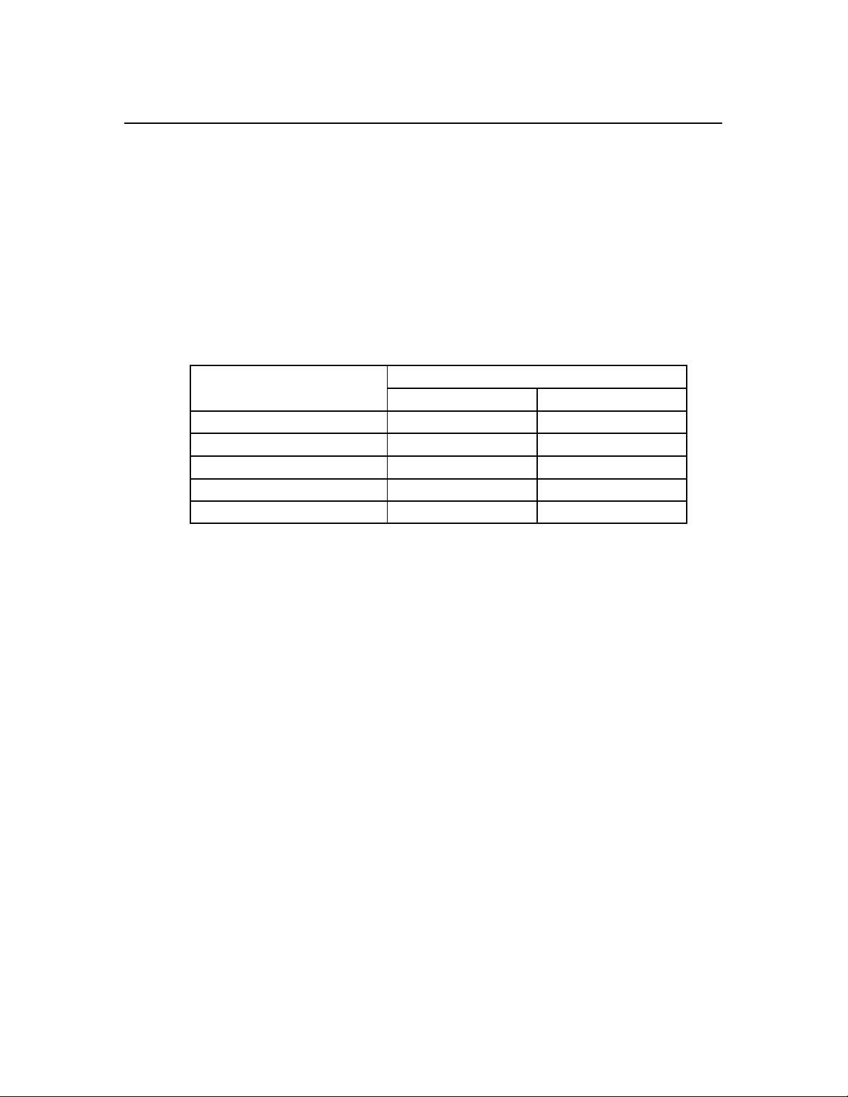
Plot Rate
100 Horiz x 96 Vert (NLQ mode) 8.3 N/A 8.3
60 Horiz x 72 Vert (DP mode) 16.7 N/A 16.7
62.5 Horiz x 64 Vert (HS mode) 18.7 N/A 8.7
50 Horiz x 48 Vert (HSB mode) 25 13.8 27.8
100 Horiz x 72 Vert (HSC mode) 8.3 13.0 10.4
The MVP–Series printers are capable of dot–addressable graphic plotting, as
well as character printing. Based on the protocol selected either P–Series or
Serial Matrix, you may select either Plot Mode or Bit Image Graphics
respectively. The plot rate specifications apply to both P–Series and Serial
Matrix types of graphic plotting. The bi–directional plot rate in inches per
minute (ipm) is shown in Table 1–2 according to the dot density in dots per
inch, (dpi). Complete plotting specifications are provided in Appendix C.
Table 1–2. Plot Rate
Plot Rate (ipm)
Density (dpi) MVP L150 150B/L150B
NOTE: Unidirectional plotting produces better print quality than
bi–directional, and can be selected from the control panel; however,
unidirectional plotting reduces the plot rate by half.
Overview 1–11
Page 22

Overview1–12
Page 23

2 Installation
Chapter Contents
Introduction 2–2. . . . . . . . . . . . . . . . . . . . . . . . . . . . . . . . . . . . . . . . . . . . . . . . . .
Power Requirements 2–3. . . . . . . . . . . . . . . . . . . . . . . . . . . . . . . . . . . . . . . . . . .
Site Requirements 2–4. . . . . . . . . . . . . . . . . . . . . . . . . . . . . . . . . . . . . . . . . . . . .
Installing the Printer 2–5. . . . . . . . . . . . . . . . . . . . . . . . . . . . . . . . . . . . . . . . . . . .
Assembling the Pedestal 2–5. . . . . . . . . . . . . . . . . . . . . . . . . . . . . . . . . . . . .
Assembling the Paper Tray 2–8. . . . . . . . . . . . . . . . . . . . . . . . . . . . . . . . . . .
Mounting the Printer onto the Pedestal 2–9. . . . . . . . . . . . . . . . . . . . . . . . . .
Attaching the Paper Tray 2–10. . . . . . . . . . . . . . . . . . . . . . . . . . . . . . . . . . . .
Table Top Mounting 2–11. . . . . . . . . . . . . . . . . . . . . . . . . . . . . . . . . . . . . . .
Applying Power 2–12. . . . . . . . . . . . . . . . . . . . . . . . . . . . . . . . . . . . . . . . . . .
Preliminary Testing 2–12. . . . . . . . . . . . . . . . . . . . . . . . . . . . . . . . . . . . . . . . . . .
Installation
2–1
Page 24

Introduction
Be sure to read this chapter carefully before installing and operating the
printer. Perform the procedures in the order presented.
The shipping restraints must be removed prior to operation to prevent
damage to the printer. In addition, the shipping restraints must be
installed whenever the printer or shuttle assembly is shipped or
transported to prevent damage.
Um Schaden am Drucker zu verhüten, vor Gebrauch die
Verpackungseinsätze entfernen. Bei Versandt oder Transport des
Druckers oder Pendelaufbaus, die Verpackungseinsätze swecks
Schadensverhütung wieder installieren.
CAUTION
VORSICHT
Installation2–2
Page 25

Power Requirements
MVP–Series printers employ a single phase, capacitive start shuttle
motor. All models require 120 volts at 4 amps for a duration of 0.5
seconds at motor start–up. This is an important power requirement and
is recommended to supply power from a separate AC circuit of 20 amps
at 60 Hz.
Die MVP Drucker benuetzen einen ein–phasigen, kapazitive–startenden
Pendelmotor. Die MVP Modelle benoetigen beim Anlassen 0,5 Sek. lang
25,4 A. Diese Stromanforderung ist wichtig und es wird empfohlen den
Strom aus einem gesonderten AC–Stromanschluss von 20 A bei 60 Hz zu
decken.
A label on the back of the printer near the power cord shows the voltage and
frequency requirements. The printer must be connected to the specified
power source, either 110, 220 or 240 volts at 50 to 60 Hz. Line voltage can
vary by 10%. The printer automatically senses and adjusts itself to conform
to the proper voltage. The printer contains primary circuit protection. Consult
an electrician if printer operation affects local electrical lines.
CAUTION
VORSICHT
Installation
2–3
Page 26

Site Requirements
When selecting a printer location, consider interface requirements, power
requirements, and environmental factors. Select a location that has the proper
power source available and is within the maximum cable length
specifications for interfacing with the host computer. The printer is designed
to operate in a relatively dust free environment such as a computer room or
business office with an ambient temperature of 5° to 40° C (41° to 104° F),
and a relative humidity of 10% to 90%. The site selected for the printer must
also allow air to circulate freely all around the printer. Finally, a minimum of
three feet clearance behind the printer should be provided to allow air
circulation and easy access to the paper stacking area.
The warranty may be voided if adequate printer ventilation is not
provided. Overheating and serious damage to printer components can
occur if the air vents at the sides and bottom of the printer are blocked.
CAUTION
VORSICHT
Die Gewährleistung könnte ungültig werden, wenn nicht genügen
Druckerlüftung vorhanden ist. Überhitzung und schweren Schaden der
Druckerkomponenten könnte vorkommen, wenn die Entlüftungsschlitze
an den Seiten und unten am Drucker blockiert sind.
Installation2–4
Page 27
Installing the Printer
If you’ve ordered the Printronix pedestal mounting kit, follow the pedestal
assembly procedures before installing the printer.
Assembling the Pedestal
To assemble the optional pedestal for pedestal model printers perform the
following steps. A 5/16 inch nut driver and 5/32 inch hex wrench are
required. Check for the following items in the pedestal ship kit before you
begin assembly:
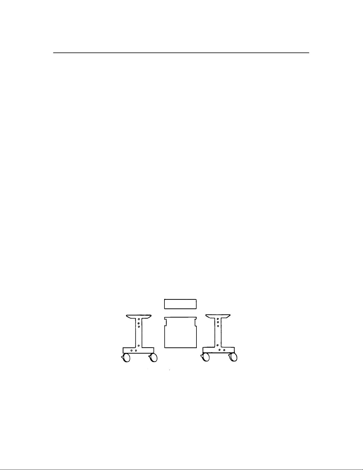
• 2 pedestal legs
• 1 modesty panel (large panel)
• 1 paper guide panel (small panel)
• 16 hex bolts
• 4 washers
• 1 paper tray
Prepare for Assembly
1. Unpack and lay the pedestal parts on the floor. The mounting holes on
the legs should face up.
Installation
2–5
Page 28
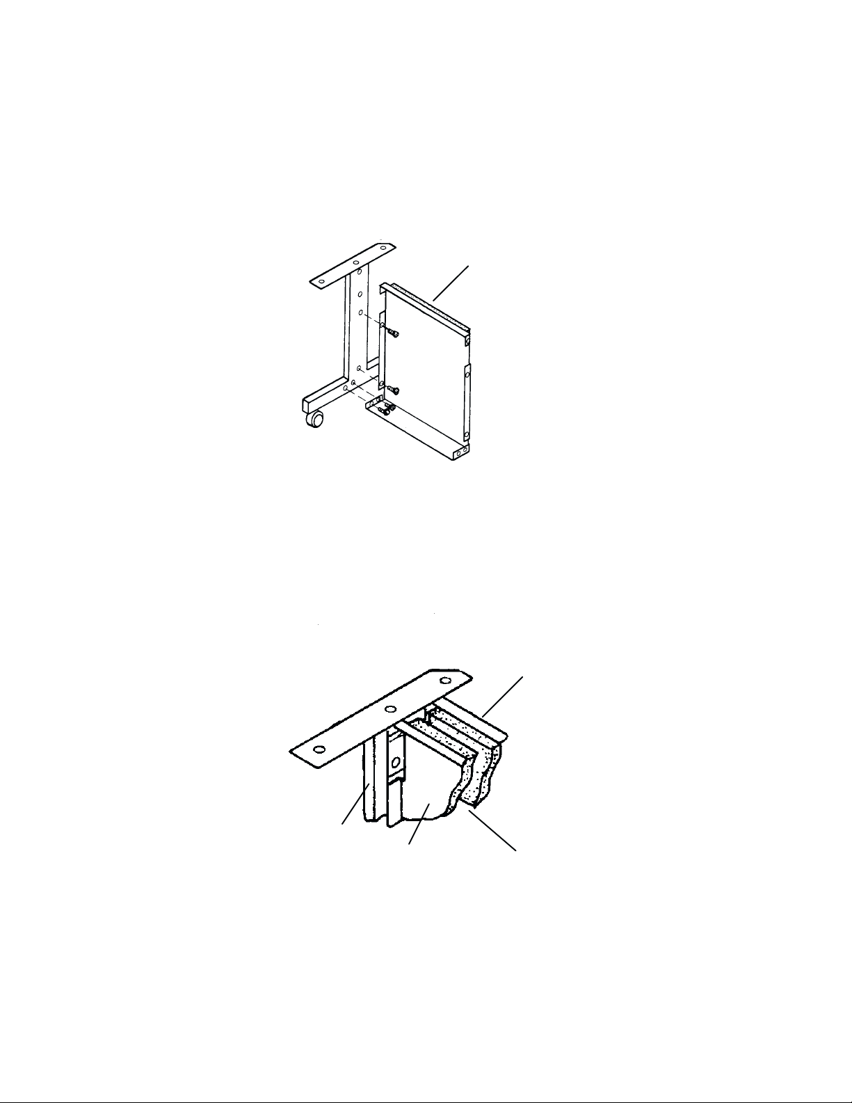
Assemble the Two Legs and Modesty Panel
2. Align the mounting holes of the modesty panel with the holes on the left
leg as illustrated. Insert and lightly tighten bolts in the two side and
bottom rear panel holes. Proceed with the right leg; align the mounting
holes, insert and lightly tighten bolts.
modesty
Add the Paper Guide Panel
panel
3. Position the paper guide panel between the modesty panel and leg
mounting holes, and align the mounting holes. The foam side of the
panels should face each other, with the foam–covered lips facing up.
pedestal
leg
modesty panel
paper guide panel
foam
Installation2–6
Page 29
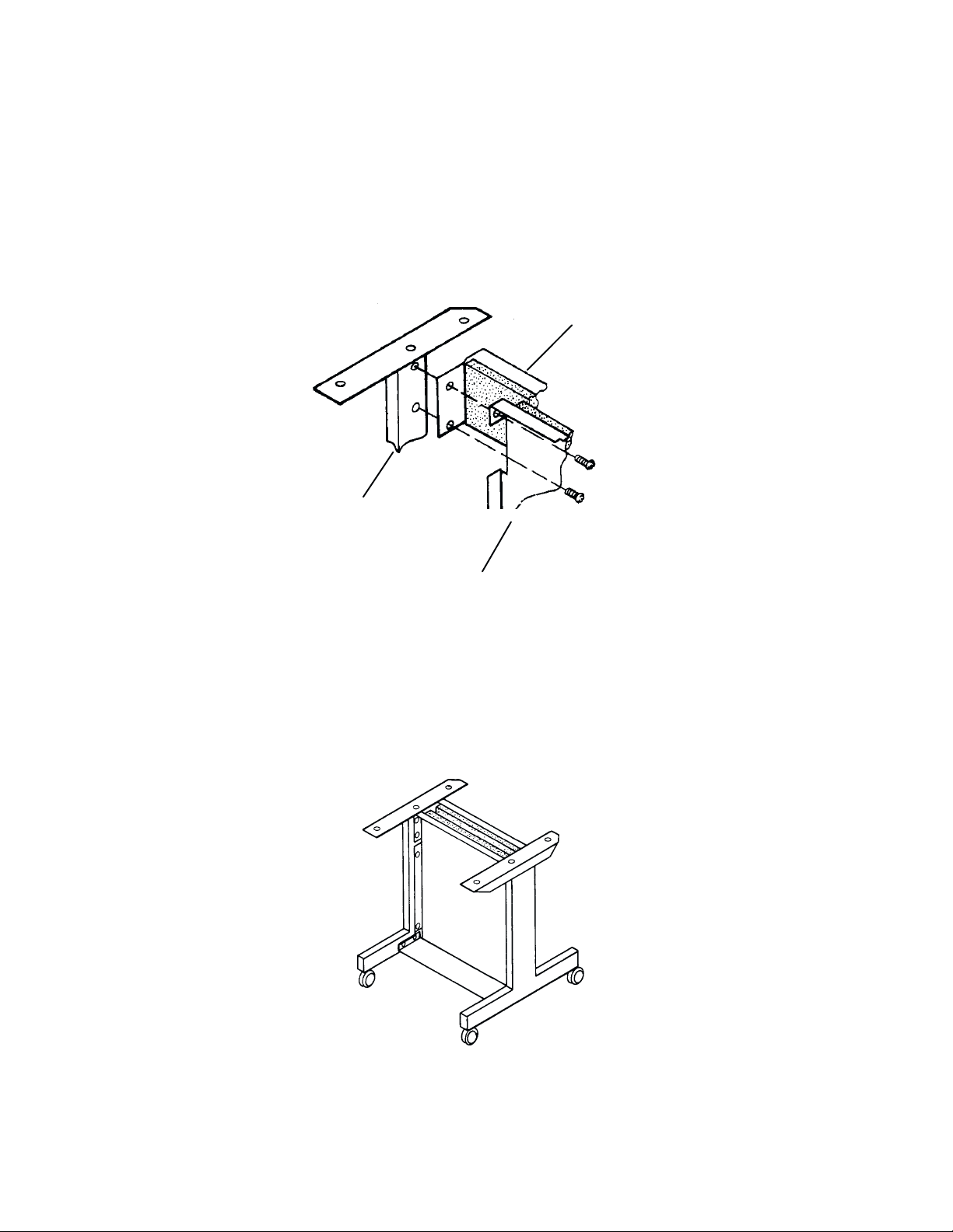
4. Insert and hand tighten bolts in the bottom left and right mounting holes
in the paper guide panel. Align the top mounting holes on the modesty
panel, paper guide panel, and left leg. Insert and hand tighten bolts
through the top left and right mounting holes.
paper
guide panel
pedestal leg
modesty panel
Adjust and Tighten
5. Firmly tighten all bolts.
Installation
2–7
Page 30
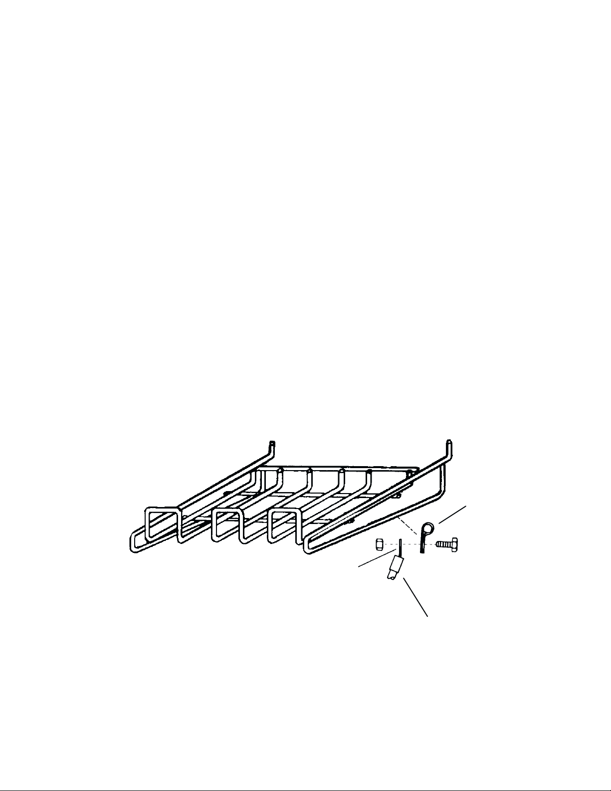
Assembling the Paper Tray
To assemble the paper tray refer to Figure 2–1, and perform the following
steps.
1. Make sure the paper tray kit contains the following items:
• 1paper tray
• 1 ground cable
• 1 clamp
• 1 screw
• 1 nut
2. Snap the clamp over the bottom right rim of the paper tray.
3. Slip the screw through the clamp and position the ground cable ring
onto the screw.
4. Thread the nut onto the screw and tighten.
ring
Figure 2–1. Assembling the Paper Tray
clamp
ground cable
Installation2–8
Page 31

Mounting the Printer onto the Pedestal
To mount the printer onto the pedestal you need a 5/32 inch Allen wrench.
1. Set the printer on a stationary table or desk. Remove the four rubber
feet from the printer by carefully sliding the printer over the edge of the
table to access two feet. Use the Allen wrench to remove the feet. Turn
the printer to the other side and remove the two remaining feet.
2. Carefully set the printer on the top of the pedestal. The front cover and
the small panel should face the same direction.
3. Align the foot mounting holes with the four holes on the top of the
pedestal. Place the washers on the four bolts and insert each through the
pedestal base as illustrated. Firmly tighten the bolts.
Installation
Figure 2–2. Mounting the Printer onto the Pedestal
2–9
Page 32

Attaching the Paper Tray
1. Hook the paper tray into the pedestal mounting holes as illustrated. Use
the upper holes when stacking small quantities of paper, and the lower
holes when stacking larger quantities.
2. Push the ground cable connector onto the protruding metal tab located
on the back of the printer, to the right of the power connector.
metal
tab
Installation2–10
Page 33

Table Top Mounting
The MVP–Series printers can be mounted on a sturdy table instead of the
pedestal. However, the table must be designed or modified to accommodate
the printer paper path and proper air ventilation.
1. Select a table sturdy enough to support the weight of the printer. If the
table is not designed for a bottom feed paper path and proper air
ventilation modify the table.
2. Make sure the four rubber feet are firmly attached to the base of the
printer.
3. Position the printer on the table so the paper will feed from under the
table, through the paper path slot, and up into the paper guide of the
printer. The paper should pass through the slot with 1/2 inch clearance at
both ends.
4. Assemble the paper tray (if used) according to the instructions in
“Assembling the Paper Tray” on page 2–8, and position it behind the
printer. Push the ground cable connector onto the protruding metal tab
located on the back of the printer, to the right of the power connector.
Installation
2–11
Page 34

Applying Power
After you properly install the printer, apply power by performing the
following steps.
1. Check that the voltage shown on the printer identification label (located
at the right rear of the printer) is the same as your power source. Voltage
in North America is usually 120 volts/60 Hz, and printers sold in the
United States are configured for power in that range. If your printer
label reads V120 VAC and your power source is also 120 volts, plug the
female end of the power cord into the male connector on the right rear
of the printer. Plug the male end into the wall outlet.
Operator hazard and printer damage is possible if the printer is
connected to an incorrect power source.
2. Press the ON/OFF switch to ON. When you press the power switch to
On, all indicators will light for approximately two seconds, and the
RDY indicator remains lit to show the printer is on–line.
WARNING
NOTE: The power On–Off switch is located at the rear of the printer and is
marked “O” for power off, and “I” for power on.
3. After loading the ribbon and paper, conduct a self–test as described in
the Routine Service and Diagnostics chapter.
Preliminary Testing
After you install and apply power to the printer, it is ready for preliminary
testing. Refer to the “Self Tests” section in the Routine Service and
Diagnostics chapter for the self–test instructions that apply to your specific
type of MVP printer. Once the self–test has been completed, examine the
print quality. The characters should be fully formed and of uniform density.
If the test does not run or characters appear malformed, contact your
authorized service representative.
Installation2–12
Page 35

3 Operation
Chapter Contents
Introduction 3–2. . . . . . . . . . . . . . . . . . . . . . . . . . . . . . . . . . . . . . . . . . . . . . . . . .
Mechanical Controls 3–2. . . . . . . . . . . . . . . . . . . . . . . . . . . . . . . . . . . . . . . . . . .
Power On–Off 3–3. . . . . . . . . . . . . . . . . . . . . . . . . . . . . . . . . . . . . . . . . . . . .
Operator Panel Switches and Indicators 3–3. . . . . . . . . . . . . . . . . . . . . . . . .
Second Function Switches 3–6. . . . . . . . . . . . . . . . . . . . . . . . . . . . . . . . . . . .
Loading Ribbon 3–8. . . . . . . . . . . . . . . . . . . . . . . . . . . . . . . . . . . . . . . . . . . . . . .
Removing the Ribbon 3–10. . . . . . . . . . . . . . . . . . . . . . . . . . . . . . . . . . . . . .
Paper Guidelines 3–11. . . . . . . . . . . . . . . . . . . . . . . . . . . . . . . . . . . . . . . . . . . . .
Paper Type and Thickness 3–11. . . . . . . . . . . . . . . . . . . . . . . . . . . . . . . . . . .
Loading Paper 3–12. . . . . . . . . . . . . . . . . . . . . . . . . . . . . . . . . . . . . . . . . . . . . . .
Removing Paper 3–15. . . . . . . . . . . . . . . . . . . . . . . . . . . . . . . . . . . . . . . . . .
Setting Top–of–Form 3–16. . . . . . . . . . . . . . . . . . . . . . . . . . . . . . . . . . . . . . . . . .
Setting Forms Length 3–17. . . . . . . . . . . . . . . . . . . . . . . . . . . . . . . . . . . . . . . . . .
Operation 3–1
Page 36

Introduction
This chapter briefly provides instructions and information on how to
manipulate the mechanical controls, power switch, external function switches
and internal function switches on MVP–Series printers.
Mechanical Controls
Become familiar with the mechanical controls for loading ribbon and paper,
adjusting the paper position and the forms adjustment thickness lever, before
you attempt to perform any procedures. Figure 3–1 is an interior view of an
MVP with the shuttle cover removed to expose various mechanical controls,
switches and indicators. Study this figure in relation to your printer to
become familiar with the positions of the items specified.
Left Tractor
(with open gate)
Shuttle
Assembly
Hammerbank
Cover Assembly
Right
Tractor
Forms Thickness
Adjustment Lever
Left
Ribbon
Guide
Shuttle
Cover
Guide
Transport
Restraining
Bolt Storage
Slots
Ribbon Hub
with Latch
Shuttle
Cover Tab
Slot
Left Transport
Restraining Bolt
Operator
Panel and
Switches
Vertical Positioning
Knob
Shuttle Assembly
Locking Knob
Right Ribbon
Guide
Shuttle Cover
Position Guide
Right Transport
Restraining Bolt
Shuttle Cover
Tab Slot
Figure 3–1. Printer Interior View (Shuttle Cover Removed)
Operation3–2
Page 37

Power On–Off
The power On–Off switch is located at the rear of the printer and is marked
“O” for power off, and “I” for power on. When you press the power switch
to “I”, all function indicators light for approximately two seconds, and the
RDY indicator remains lit to show the printer is on–line.
Operator Panel Switches and Indicators
The operator panel has five switches with indicators, and a three–digit
numerical display (Figure 3–2). The switches, labeled RDY, CHK, 8LPI and
TOF, each have a small Light Emitting Diode (LED) indicator.
Digital
Panel
MODE
RDY
F/L
CHK
ADDR
8LPI
DATA
TOF
2nd
FUNC
SwitchIndicator
Figure 3–2. Operator Panel
NOTE: Printer will not operate if the CHK indicator is flashing.
When you turn the printer on, all four indicators light for approximately two
seconds. However, the RDY indicator remains lit to show the printer is
controlled by the host computer, on–line and ready to print.
You can only use the CHK, 8LPI and TOF switches when the printer is
off–line. To take the printer off–line, press the RDY switch until the indicator
flashes. The flashing indicator shows the printer is not controlled by the host
computer, and is off–line. The following descriptions outline the switches in
more detail.
Operation 3–3
Page 38

RDY (Ready)
Purpose Indicates the printer is on–line and ready to print.
Status When the indicator is flashing, the printer is off–line.
When the indicator is lit, the printer is on–line.
Action To put the printer on–line; press and release, until the indicator is lit.
To take the printer off–line; press and release, until the indicator flashes.
Result When the printer is on–line, none of the other switches are active.
When the printer is off–line, use the front panel function keys.
Other If the printer is connected to the host, the host controls the printer when it is
on–line. When the printer is off–line, the host no longer has control.
CHK (CHECK)
Purpose Indicates there is a problem or malfunction.
Status When the indicator is lit or flashing the printer is malfunctioning. A fault
code indicating the type of problem will appear in the display. (Explanations
of the codes are in Appendix B.)
Action If the indicator is flashing, check the fault code, fix the problem and reset the
printer by pressing and releasing. If the indicator is lit, it is more than likely
the printer needs to be serviced.
Other On occasion, you may be able to correct a steady indicator problem by
pressing and releasing.
NOTE: The printer will not operate when the indicator is flashing or is lit.
Therefore, you must take some action to restore the printer to
working order.
8LPI (8 Lines Per Inch)
Purpose Allows for alternate spacing of either 8, 9 or 10 lines per inch. The default is
6 LPI.
Status When the indicator is lit, an alternate LPI is selected.
Action To select an alternate LPI, press and release until the desired LPI is selected.
Other Alternate spacing options are only available when the appropriate value has
been assigned to printer configuration option 51. (See the Configuration
chapter for more details on configuration options.) Line spacing may also be
controlled by the host by using the appropriate command sequences. If an
alternate LPI is selected, the 8LPI indicator will be lit, as if it were set from
the panel.
Operation3–4
Page 39

TOF (Top–of–Form)
Purpose Advances the paper or adjusts top–of–form one line or one page at a time.
Status The indicator is always off, you must press to activate.
Action To move the paper one line; press and release very quickly. To move the
paper one page or the to the top of the next form; press and hold for about
one second.
Other Reset the TOF each time you load paper. Setting TOF after a paper load is
described on page 3–16.
F/L (Form Length)
Purpose Allows the top of the page to begin in the same place on unusual length
forms.
Status The indicator is always off.
Action Press to activate.
Other Paper that is a nonstandard length will need to have the new length set. You
can select any length from 3 inches to 24 inches in one–half inch increments.
Operation 3–5
Page 40

Second Function Switches
The operator panel has second function capabilities, and you can access them
by pressing the 2nd FUNC key with either the MODE, F/L, ADDR or TOF
switches. The printer configuration set at the factory will satisfy most
printing requirements. However, when it becomes necessary to modify the
way the printer responds to commands (printer reconfiguration) use the
second function features. See page 4–4for further information on
reconfiguration.
The second function switches also allow you to change print modes, set
forms length, top–of–form and print various self–test patterns. The following
descriptions outline the switches in more detail.
2nd FUNC
Purpose Activates second operation of selected switches or returns to normal
operation.
Status The indicator is always off, you must press to activate.
Action When the indicator is lit, the printer is in 2nd FUNC mode.
When the indicator is off, the printer is in the normal operation mode.
Result When the indicator is lit, only the MODE, F/L, ADDR and TOF can be used.
MODE
Purpose Selects print modes 1–5 (1–6 for 150B printers).
Status The indicator is always off, you must press to activate.
Action Press and release to display current mode.
To select desired print mode, press and release to cycle through print modes
by 001.
Result After selecting print mode, press and release 2nd FUNC to print in the
selected print mode.
Other The selected print mode will continuously display during printing. Refer to
page 5–5for detailed printer mode specifications.
Operation3–6
Page 41

F/L
Purpose Sets forms length from 3.0 to 24.0 inches in 0.5 increments. Verifies proper
forms length when changing paper. See page 4–36 for proper configuration.
See page 3–17 for the procedure to set the forms length.
Status The indicator is always off, you must press to activate.
Action Press and release to display current length.
To select desired forms length, press and release to advance by 0.5
increments. Press and hold for rapid advance. Display cycles from 03.0 to
24.0 inches.
Result After selecting print mode, press and release 2nd FUNC to print with the
selected forms length.
ADDR
Purpose Selects and changes the configuration address in the numeric display
(00 – 99).
Status The indicator is always off, you must press to activate.
Action Press and release to display current two–digit memory address code.
To select desired address, press and release to advance by 01 increments.
Press and hold for rapid advance. Display cycles from 00 to 99.
Result After selecting the desired print test, press and release 2nd FUNC to print
the selected table or test pattern.
Other See page 9–10 for the Self–Test Procedure.
Refer to page 4–3for the Configuration Change Procedure.
DATA
Purpose Selects one of up to nine options (.0 – .9) for each configuration address.
Status The indicator is always off, you must press to activate.
Action Refer to page 9–10 for the Self–Test Procedure.
Refer to page 4–3for the Configuration Change Procedure.
Operation 3–7
Page 42

Loading Ribbon
The standard ribbon for MVP–Series printers is nylon fabric, one–inch by 60
yards, spool to spool, (Printronix part number 107675). The ribbon rewinds
automatically to the supply side when installed, so either spool may be
installed on either hub. The ribbon should be replaced when the print contrast
is too low, or approximately after each box of standard size computer paper
is used.
To load the ribbon, lift the printer cover and perform the following steps.
NOTE: The power does not need to be on when you load the ribbon. If it is,
1. Move the forms thickness adjustment lever to the base of the printer as
far as it will go. (If the power is on, the CHK indicator will flash when
you move the lever.) The ribbon mask in back of the ruler will separate
slightly.
make sure the RDY light is flashing.
Forms Adjustment
Thickness Lever
2. Place one spool of ribbon on a hub so the locking latch snaps into place
and the ribbon unwinds toward the outside.
Locking
Latch
Hub
Operation3–8
Page 43

3. Pass the ribbon around the ribbon guides. Carefully place the ribbon
between the ribbon mask and the ribbon guides, ensuring the ribbon is
not twisted. Place the second spool of ribbon on the other hub so the
locking latch snaps into place and the ribbon winds toward the inside.
Adjust the tension by hand–winding the spool.
Ribbon
Guides
NOTE: A twisted ribbon will affect the print quality, shorten the ribbon life,
and cause a paper or shuttle jam.
4. If paper is loaded, adjust the forms thickness adjustment lever for the
appropriate position that is correct for the thickness of the paper.
Pointer
5. If the printer power remained on during ribbon loading, press the CHK
switch. If there is no paper in the printer, the CHK indicator will
continue to flash.
NOTE: Ribbon loading directions are also shown on the black plastic
shuttle cover inside the printer.
Operation 3–9
Page 44

Removing the Ribbon
To remove the ribbon refer to the illustrations in “Loading the Ribbon,” and
perform the following steps.
1. Move the forms thickness adjustment lever to the base of the printer as
far as it will go. (If the power is on, the CHK indicator will flash when
you move the lever back.) The ribbon mask in back of the ruler will
separate slightly.
2. Release the locking latch on one hub and lift the spool.
3. Carefully remove the ribbon from around the ribbon guides and out of
the ribbon mask.
4. Remove the second spool from its hub.
Operation3–10
Page 45

Paper Guidelines
Paper used with the MVP–Series printers must meet the following
guidelines:
• One–to–six parts, with or without carbon, continuous, and fan–folded
• Six–edge standard sprocket holes
• From 3 to 16 inches wide, including strips with the sprocket holes
• From 3 to 24 inches long
• Uniform thickness, including the sprocket hole edge strips, not to
exceed 0.025 inches
• 15 to 100 lb. stock
• Interleaf attachment must not be metal or other hard material
• Labels on backing must be at least 1/16–inch from the fan–fold edge
perforation and not have excess adhesive that can be pressed out when
the label is printed
• Fan–fold forms should go through the printer without bunching or any
distortion of the paper
Paper Type and Thickness
Paper type and thickness will affect print quality. Therefore, take both
thickness and type under consideration when determining where to position
the forms thickness adjustment lever. The three ridges on the lever are
reference points for paper thickness that can be from one–to–six parts thick.
The forward (closed) lever position is for thinner paper. The back (open)
lever position is for thicker paper. For example, the forms thickness
adjustment lever should be positioned near the middle ridge when using
three–part paper and usually at the last ridge for one–part paper.
NOTE: Always use full size computer paper (9
when performing self–tests.
1
/2 x 11 inches or larger)
Operation 3–11
Page 46

Loading Paper
To load paper lift the printer cover and perform the following steps. Read all
of the instructions before loading the paper.
NOTE: The power does not need to be on when you load paper. If it is,
1. Move the forms thickness adjustment lever to the base of the printer as
make sure the RDY light is flashing.
far as it will go. (If the power is on, the CHK indicator will flash when
the lever is moved or when the printer is out of paper.)
Forms AdjustmentThickness Lever
2. Pull the right tractor lever (the plastic lever to the right of the tractor)
down to unlock it, then open both tractor gates. If you keep the left
tractor stationary you will have less to adjust later.
NOTE: The tractor levers on some printers must be pulled up to unlock and
pulled down to lock.
Operation3–12
Page 47

3. Feed the paper into the slot from underneath if the printer is on a
pedestal or from the front if the printer has a front feed attachment.
Continue to feed the paper until it passes between the ribbon mask and
the wide metal bar.
Paper
Slot
Pedestal
4. Load paper on the left tractor sprocket pins and close the tractor gate.
Load paper on the right tractor sprocket pin. Make sure the paper is
aligned horizontally (the correct holes are across from one another), and
close the right tractor gate.
Sprocket Holes
5. If the left tractor was kept stationary, proceed to step 7. If not, slide both
tractors so that the edge of the paper lines up with the first mark on the
printer’s ruler, or where you want the left margin to print. Lock the left
tractor lever (the black lever).
Ruler
Operation 3–13
Page 48

6. Adjust the right tractor so that the paper has just enough tension to be
flat and taut without pulling. Pull the right tractor up to lock it.
NOTE: Too much or too little paper tension may distort the sprocket holes
and cause problems in paper feeding or printing.
7. Advance the paper with the positioning knob so the paper will feed out
of the opening between the raised cover and the top of the printer. Make
sure the paper supply from the bottom will feed into the printer in a
straight line.
Positioning Knob
8. Adjust the forms thickness adjustment lever to the appropriate paper
thickness. Refer to “Paper Type and Thickness” on page 3–11.
Pointer
9. If the power was on while you loaded the paper, press the CHK switch.
If the power was off, turn the power on and then press and release the
RDY switch.
10. Set top–of–form (TOF). Top–of–form should be set each time the paper
is loaded, refer to “Setting Top–of–Form” on page 3–16.
Operation3–14
Page 49

Removing Paper
To remove paper, follow these steps.
1. Tear off the paper at the first perforation just under the printer.
Pulling the paper down through the printer could damage the printing
mechanisms.
2. Move the forms thickness adjustment lever to the base of the printer as
far as it will go.
3. Open both tractor gates and lift the paper from the sprockets.
4. Pull the paper carefully upward and out of the printer.
CAUTION
Operation 3–15
Page 50

Setting Top–of–Form
To set the top–of–form, perform the following steps.
1. Make sure the power is on and the RDY indicator is flashing.
2. Move the forms thickness adjustment lever to the fully open position.
3. The TOF alignment pointer allows you to set the first print line on the
paper or form. Use the vertical positioning knob to align the top of the
first print line with the TOF alignment pointers.
vertical positioning knob
4. Adjust the forms thickness adjustment lever for the appropriate paper
thickness.
5. Perform the following procedure on the operator’s panel:
a. Press CHK to clear the “check” condition.
b. Press and hold the 2nd FUNC switch, then press and quickly
release the TOF switch. Release the 2nd FUNC switch.
c. Press and hold the TOF switch for about one second; this action
advances the paper to the top of the next form.
d. Press the RDY switch to set the printer ready for printing (on–line).
Operation3–16
Page 51

Setting Forms Length
To set the forms length, follow these steps.
1. Press and release the 2nd FUNC switch.
2. Press the F/L switch; the indicator will remain lit and the current forms
length will display on the digital panel.
3. Press and quickly release the F/L switch to advance the number by 1/2
inch or press and hold the F/L switch until the number you want
displays. After the number advances to 24 (24.0), it will automatically
begin again at 3 (3.0).
4. If you want the printer ON–LINE, (ready to print) after setting the new
forms length, press the 2nd FUNC switch to turn its indicator off. When
the indicator goes off, the RDY indicator will flash. Press the RDY
switch.
NOTE: If you want to return to your original forms length setting, reset to
that length by following the directions above or turn the power off
and the current forms length will reset automatically. Forms length
displayed can be from either the host computer or the printer
EAROM. Pressing the F/L switch will reset forms length to the
EAROM value resulting in a forms length different than that
generated by the host. Host forms length can be defined in either
inches ()1.0 to 22.0) or lines (001 to 127). Only forms length in
inches can be specified from the printer front panel.
Operation 3–17
Page 52

Operation3–18
Page 53

4Configuration
Chapter Contents
Introduction 4–2. . . . . . . . . . . . . . . . . . . . . . . . . . . . . . . . . . . . . . . . . . . . . . . . . .
Changing Configurations 4–3. . . . . . . . . . . . . . . . . . . . . . . . . . . . . . . . . . . . . . . .
MVP/L150 4–3. . . . . . . . . . . . . . . . . . . . . . . . . . . . . . . . . . . . . . . . . . . . . . .
150B /L150B 4–4. . . . . . . . . . . . . . . . . . . . . . . . . . . . . . . . . . . . . . . . . . . . .
Verifying Configurations 4–5. . . . . . . . . . . . . . . . . . . . . . . . . . . . . . . . . . . . . . . .
Configuration Options 4–6. . . . . . . . . . . . . . . . . . . . . . . . . . . . . . . . . . . . . . . . . .
Quick Reference Table for Configuration Options 20–59 4–7. . . . . . . . . . . .
Configuration 4–1
Page 54

Introduction
Configuration refers to a set of option choices that define printer responses to
operational commands. The printer responds to the particular set of
commands it receives through either user–selected configuration choices or
factory defaults that are functional unless you reconfigure a specific default.
NOTE: Configuration options must be provided for printer control firmware
The printer can be configured by one of three methods:
• Factory default options that take effect when the printer is turned on,
• Partial or total options set by you that take effect when the printer is
• Options entered by you after the printer is turned on.
locations.
provided no other options have been set.
turned on.
The ADDR and DATA keys are used to select the available configurations
and options. The ADDR key is used to select the configuration number, and
the DATA key is used to select the option number.
The display at the left of the operator’s panel shows a three–digit
configuration number in the form of XX.Y, where:
• The two left digits (XX) represent the current configuration address
from 00 to 99.
• The right digit (or third digit), (.Y), represents the option number from
.0 to .9.
MODE
RDY
F/L
CHK
ADDR
8LPI
DATA
TOF
2nd
FUNC
XXY
Figure 4–1. Operator’s Control Panel
Configuration4–2
Page 55

Changing Configurations
You can change configuration options by following the procedure particular
to your MVP printer. For 150B and L150B printers, the configuration option
procedures release the Configuration Safety Lockout, then locks it after
changes are made.
MVP/L150
1. Press and release the RDY switch until the indicator flashes.
2. Press and release the 2nd FUNC switch until the indicator lights.
3. Press and release the ADDR key until the display shows a configuration
option.
NOTE: Continue pressing and releasing ADDR until the desired
configuration option displays. To view any of the values, press and
hold ADDR. The displayed configuration option numbers cycle
through 00 to 99.
4. First press and hold the DATA key, then press and release the MODE
switch until the DATA indicator lights. Release DATA when the current
configuration option and number displays.
5. Repeatedly press and release DATA until the desired configuration
number displays.
6. Press ADDR to load the configuration and its number, and to advance to
the next configuration option.
7. Press 2nd FUNC to exit .
NOTE: If values in configuration options 67–90 are changed, turn the
printer off and on after all configurations are keyed in to reinitialize
the serial version, USART
8. Repeat steps 1 thru 7 until all desired configurations are made.
Configuration 4–3
Page 56

150B/L150B
1. Press and release the RDY switch until the indicator flashes.
2. Press and release the 2nd FUNC switch until the indicator lights.
3. Press and hold the ADDR key until the display shows 16.0. Press and
release the DATA key until the display reads 16.3.
4. Press and release 2nd FUNC until the RDY indicator flashes.
NOTE: At this point, the printer is off–line and ready to enable
5. Press and release 2nd FUNC until the indicator lights, then press and
release ADDR. The current configuration option and number will
display.
6. Press and release ADDR to advance the configuration options by 01.
reconfiguration. Repeat steps 5 thru 9 until all desired
configurations are made.
NOTE: Pressing and holding ADDR will advance the options continuously;
release it when the desired configuration displays.
7. First press and hold DATA, then press and release MODE to select the
third digit. When the digit is selected, release DATA.
8. Press and release DATA to advance the third digit by 01. Repeatedly
press and release it until the desired configuration number displays.
9. Press and release 2nd FUNC to put the new option number into printer
memory. Press and hold ADDR until the display reads 16.3
10. Press and release DATA until the display reads 16.4; this step locks out
accidental reconfiguration.
11. Press and release 2nd FUNC to return the printer to off–line, and to lock
in the new configuration.
Configuration4–4
Page 57

Verifying Configurations
Verify the printer configuration to ensure that the appropriate response is
received for a particular application. To verify a configuration:
1. Print out a configuration self–test using the Self Test Procedure on page
9–10to set the configuration option to 00.1. (Make sure the printer is
on–line.)
2. Compare the values of configuration options 20 through 99 with
application requirements. Refer to the “Self–Tests” in Chapter 9 for a
complete list of self–tests and instructions that apply to your type of
MVP printer.
3. Use the explanations for configuration options 20 through 99 to
determine the configuration settings selected.
NOTE: Use the explanations for configuration options 20 through 99 to
determine the configuration settings selected. Explanations for
standard MVP/L150 and 150B/L150B configuration options 20–59
begin on page 4–7. Configuration options 60 through 99 are
discussed in the Interfaces chapter. Addresses 00–19 are test and
service printout addresses.
4. Change the configuration options as necessary to meet application and
interface requirements.
Configuration 4–5
Page 58

Configuration Options
After assembling and interfacing the printer, configuration changes are
usually limited to configuration options 20 through 59. Options 60 through
99 are only changed when it is necessary to reconfigure the printer for a new
interface. Configuration addresses 00 through 19 are print and service tests.
Table 4–1 is a sequential cross–reference of Standard MVP/L150 and
150B/L150B Configuration Options 20 through 59. Use the page numbers to
access the option descriptions.
Configuration4–6
Page 59

Table 4–1. Quick Reference Table for Configuration Options 20 – 59 1
Configuration
Number
20 MVP/L150 Host Mode Control Programming Standard 4–8
20 150B/L150B
21 All Vertical Dot Density 4–10
22 All Insert automatic Line Feed in Data Stream 4–11
23 All Automatic Line Feed on Carriage Return 4–12
24 All Inhibit Lowercase/Underline and T
25 All Binary Count Slew 4–14
26 All Printer On–line with Power On 4–15
27 All Paper Out Delay 4–16
28 All Underline 4–17
29 All Delete 4–18
30 All Print or Graphics Mode at Power On 4–19
31–41 MVP/L150
31–41 150B/L150B
42 All Electronic Vertical Format Unit (EVFU) 4–27
Printer Type Configuration Option Page #
Double W
Control Code Assignments
Control Code Assignments
ide Print Operation (Expanded Print Select) 4–9
ranslate Lowercase to Uppercase
4–13
4–20
4–25
43 All Plotting Exit 4–28
44 All Buffer Print with Top–of–Form (TOF) 4–29
45 150B/L150B
46 150B/L150B EVFU Control with no PI 4–31
47 150B/L150B SOH and ETX 21 4–32
48 150B/L150B Character Per Inch in Mode 5 4–33
50 All Page Perforation Skip 4–34
51 All Lines Per Inch (LPI) Line Spacing 4–35
52 All Forms Length at Printer Powerup 4–36
54 150B/L150B Lines Per Inch–Line Spacing at Power Up 4–37
56 150B/L150B Column Print Spacing 4–37
57 150B/L150B Input Buffer Sizes 4–38
58 150B/L150B
59 150B/L150B Version 4–38
Mode 4
ESC DC1 Sequence
4–30
4–38
NOTE: Options 60–99 are located in Chapter 8 beginning on page 8–8.
Configuration 4–7
Page 60

Option 20 — Host Mode Control Programming Standard
Discussion
Option 20.0 is used to store data that allows you to select the Host Mode
Control. Option 20.1 allows up to 11 beginning characters (or headers) of
control code sequences that are valid when encountered in the data stream;
option 20.2 allows only one.
MVP/L150
Option
Number
.0 20.0 Host Mode Control disabled (default)
.1 20.1 P–Series programming standard. (Control Code sequence for more
.2 20.2 ANSI programming standard. Control Code sequence for mode
Display Configuration
Description
changes appearing in data stream are edited per conditions attached
to Configuration options 31 through 41.)
change must begin with ESC (1BH).
Configuration4–8
Page 61

Option 20 — Double Wide Print Operation (Expanded Print Select)
Discussion
Option 20 makes it possible to print “double wide” characters. The term
“double wide” is related in an inverse manner to pitch, and generally alludes
to the width of alphanumeric characters just before the double wide feature is
invoked.
150B/L150B
Option
Number
.0 20.0
.1 20.1 Per character width doubling through control codes (Modes 1– 5)
Display Configuration
Description
Double wide on per line basis only
either control code ESC SO or SO (see page 7–31). If the printer is
operating at 10 pitch when the control code is executed, printer
operation shifts to pitch 5. However, if the printer is operating at
16.7 pitch (Mode 5) when the control code is executed, printer
operation changes to 10 pitch. If control code DC4 is received
within that same line, it cancels any ef
produced. See Note.
but excludes bit image characters. Default. Disables Mode 6.
See Note
. Enables Mode 6. Initiated by
fect that ESC SO might have
NOTE: When executed, any one of the following codes causes the pitch to
change by one–half: (1) SO, (TEXT), LF produces a line of double
wide characters; (2) SO, (TEXT), DC4, LF produces a line at
whatever pitch is in effect at the time the line is received; or, (3)
ESC W CHR$ (1 or 49) will cause each succeeding line to have
double wide characters.
Characters are produced at the reduced pitch until: the end of the
line (printing takes place); a DC $ is received; or, in the case of ESC
W n, an ESC W CHR$ (0 or 48) is received. Printing then resumes
at the pitch rate in effect before the double wide feature was
executed. For example, a line coded A (SO) B (DC4) C LF will be
printed with “A” and “C” normal pitch and “B” double wide.
Configuration 4–9
Page 62

Option 21 — Vertical Dot Density
Discussion
Option 21 permits a four percent increase in vertical dot density. (The
Density Option paper feed pulley must be installed for proper operation.)
MVP/L150
Option
Number
.0 21.0 Enable standard P–Series compatible vertical dot density (default).
.1 21.1 Enable increased vertical dot density (with Density Option paper
Display Configuration
150B/L150B
Option 21 must be set to 21.0.
Description
feed pulley installed).
Configuration4–10
Page 63

Option 22 — Insert Automatic Line Feed in Data Stream
Discussion
Normally, Option 22 is disabled. When it is enabled, a line feed is
automatically inserted into the data stream after the last character in a
character line.
MVP/L150
Option
Number
.0 22.0 Disable (default). No line feed inserted. Refer to the related table in
.1
.2
.3
.4
150B/L150B
Option
Number
.0 22.0 Automatic line feed inserted after 255 characters in all modes
.1 22.1
Display Configuration
Description
the Programming chapter.
22.1 Insert after 132nd character in Modes 001, 002 and 005 and after
165th character in Mode 003.
22.2 Insert after 104th character in Modes 001, 002, and 004 and after
132nd character in Modes 003 and 005.
22.3 Insert after 80th character in Modes 001 and 002, after 100th
character in Mode 003 and after 132nd character in Mode 005.
22.4 Insert after 80th character in Modes 001, 002, 003 and 005.
Display Configuration
Description
(default).
The table below shows where the automatic line feed is inserted,
depending on which mode you are in.
22.1* 22.2* 22.3* 22.4* 22.1**
Mode 1 132 104 80 80 136
Mode 2 132 104 80 80 136
Mode 3 165 132 100 80 170
Mode 4 220 132 132 80 136
Mode 5 220 176 132 80 238
* = W
ith Configuration Option 56.0
** = W
ith Configuration Option 56.1
Configuration 4–11
Page 64

Option 23 — Automatic Line Feed on Carriage Return
Discussion
Carriage return (0DH) does not cause a line feed and the character line is not
printed in the default configuration. The character line must be terminated
with a Form Feed, Line Feed, or EVFU (Electronic Vertical Format Unit)
command before it is printed. In other configurations, carriage return
generates 1, 2, or 3 line feeds.
MVP/L150
Option
Number
.0 23.0 CR = 0 line feed (default)
.1 23.1
.2 23.2
.3 23.3
Display Configuration
Description
CR = 1 line feed
CR = 2 line feeds
CR = 3 line feeds
NOTE: The Underline feature, Configuration Option 28, cannot be used if
option 23.1–.3 is selected. These options set CR equal to one, two,
or three line feeds, respectively, and cause the printer buffer
contents to be printed before the underlines can be loaded into the
buffer. The underlines are then printed one, two, or three lines
below the desired position. A line terminator other than a carriage
return (e.g, FF or EVFU terminator) must be used if 23.0 is not
selected.
150B/L150B
Option
Number
.0 23.0 No line feed on CR (default)
.1 23.1
.2 23.2
.3 23.3
Display Configuration
Description
CR = 1 line feed
CR = 2 line feeds
CR = 3 line feeds
NOTE: Use of option numbers .1–.3 requires that underlining be performed
using either BS or ESC, –; n. See configuration option 28.1.
Configuration4–12
Page 65

Option 24 — Inhibit Lowercase/Underline and Translate
Lowercase to Uppercase
Discussion
Normally, underlines and lowercase characters are produced in the default
configuration. When Option 24 is enabled, lowercase characters and
underlines are inhibited for all modes.
MVP/L150
Option
Number
.0 24.0 Disable (default). Provides underline and lowercase.
.1 24.1 Enable. Provides uppercase only and no underlines in all modes.
Display Configuration
150B/L150B
Option 24 must be set to 24.0.
Description
Configuration 4–13
Page 66

Option 25 — Binary Count Slew
MVP/L150
Option
Number
.0 25.0 With Control Code 10H (binary count of 0) causes one line slew,
.1 25.1 W
Display Configuration
Description
11H (binary count of 1) causes a two line slew
ments by one up to Control Code 1FH (binary count of 15) which
causes a 16 line slew
ith set, the entire sequence is shifted by one so that Control Code
10H (binary count of 0) causes a 16 line slew instead of one, 11H
causes a one line slew
causes a 15 line slew
.
, and Control Code 1FH (binary count of 15)
.
NOTE: If Paper Instruction (PI) is enabled by configuration option 61.1,
option 25 enables the user to shift the values for the line slew
control codes by one. Note that a single PI (hex 00) command will
slew a blank line.
150B/L150B
Option
Number
.0 25.0 Slew 1 to 16 lines for line terminators PI (hex 00) thru PI (hex 0F).
.1 25.1 Slew 1 to 15 lines for line terminators PI (hex 00) thru PI (hex 0F).
Display Configuration
Description
PI (hex 00) and PI (hex 01).
, and each code incre
-
NOTE: Note that a single PI (hex00) command will slew a blank line. The
distance between each P–Series plot dot row will be wrong if ESC
or SOH ’3’n or ’A’n is active. However, single PI (hex 00 – hex 0F
or EVFU slew commands will slew lines with vertical line spacing
set with ESC or S0H ’3’n or ’A’n commands. In addition to the
ESC and S0H start header characters, the ETX character is also
allowed (Hex 03).
Configuration4–14
Page 67

Option 26 — Printer On–line with Power On
Discussion
Normally when the printer is turned on, the RDY switch must be pressed
before the printer is on–line. When Option 26 is enabled, the printer is
automatically on–line when the printer is turned on.
MVP/L150
Option
Number
.0 26.0 Disable (default)
.1 26.1 Enable
150B/L150B
Option
Number
.0 26.0 On–line with power on disabled (default)
.1 26.1 On–line with power on enabled.
Display Configuration
Description
Display Configuration
Description
Configuration 4–15
Page 68

Option 27 — Paper Out Delay
Discussion
Normally when the printer is out of paper, it will stop printing after the
current line has been printed. Option 27 allows printing to continue until the
next form feed (FF) is received or until the end of the page reaches the print
hammers (typically an additional 1.1 inch of print).
MVP/L150
Option
Number
.0 27.0 Print current line only (default).
.1 27.1 Print to end of form. Permits printing of data until either the next
150B/L150B
Option
Number
.0 27.0 Stop immediately when out of paper (default).
.1 27.1 Print additional 1.1 inches when out of paper.
Display Configuration
Description
form feed character is received or an additional 1.1 inches (nominal) of printing or plotting has been performed, whichever comes
first.
Display Configuration
Description
Configuration4–16
Page 69

Option 28 — Underline
Discussion
When 28.0 is selected and Option 23.0 is selected (CR=0 line feeds),
characters can be underlined in the present character line.
MVP/L150
Option
Number
.0 28.0 Enable underline (default).
.1 28.1
Display Configuration
Description
Disable underline.
NOTE: Configuration Options 23.1, 23.2, and 23.3 effectively disables
underlining if CR is used as the line terminator. Underlines will still
be printed; however, they will print 1, 2, or 3 lines below the text
based on the CR option selected, 23.1, 23.2, or 23.3.
150B/L150B
Option
Number
.0 28.0
.1 28.1
Display Configuration
Description
Leading and trailing spaces are suppressed for automatic
underline (default).
Underline all blank spaces.
Configuration 4–17
Page 70

Option 29 — Delete Code 7F
Discussion
When a DEL (Delete) code is received, either a character from a font or a
space may be printed depending on the configuration option selected.
MVP/L150
Option
Number
.0 29.0 Enable space response to DEL code (default).
.1 29.1 Disable. Prints whatever character is in the font PROM at the DEL
Display Configuration
Description
code address.
150B/L150B
Option
Number
.0 29.0 DEL codes (7FH and FFH) are printable characters (default).
.1 29.1
.2 29.2 DEL codes are ignored in data stream.
Display Configuration
Description
DEL codes are destructive back spaces.
NOTE: This option is only available on printers equipped with V50. 59
DCU and MCU 20.25 (or later) firmware and primary font PROM
116043–001 or equivalent.
Configuration4–18
Page 71

Option 30 — Print or Graphics Mode at Power On
MVP/L150
Option
Number
.0 30.0
.1 30.1
Display Configuration
Description
Enable Mode 002 – Data Processing (default).
Mode 001 –
Enable
Corresponding/Word Processing
(high resolution graphics)
.2 30.2
Enable
Mode 003 –
Compressed Print
(medium resolution graphics)
.3 30.3
Enable
Mode 004 –
High Speed Plot
(low resolution graphics)
.4 30.4
Enable
Mode 005–
Condensed Print
(medium resolution graphics)
.5 30.5 Save current mode when the printer is turned off.
NOTE: For the L150, Mode 002 should be selected when the optional
Intelligent Graphics Processor (IGP) board is being used to ensure
correctly scaled graphics.
150B/L150B
Option
Number
.0 30.0
.1 30.1
.2 30.2 Enable
.3 30.3
.4 30.4
Display Configuration
Description
Enable Mode 002 – Data Processing (default).
Mode 001 –
Enable
Mode 003– Draft Mode
Enable Mode 004 –
45.0 and 59.0 are enabled; Draft Mode when 45.1 and 59.0; 72.5 x
72 dpi Bar Code Mode when 59.1.
Enable Mode 005– Condensed Print when when Configuration
Option 59.0 is enabled; 80 x 72 dpi Bar Code Mode when 59.1.
Corresponding/Word Processing
High Speed Plot when Configuration Options
Configuration 4–19
Page 72

Options 31–41 — Control Code Assignments
Discussion
Eleven configuration options are included in this group. Each option has ten
configuration selections that can be assigned to an associated control code.
When the control code assigned to a specific configuration option appears in
the data stream, the printer will operate in response to the selection in that
option.
For example, if Configuration Option 33.4 (8 lpi) is set, code 03 Hex (ETX)
functions as Code 06 Hex (ACK), the code that causes the printer to shift
from 6 lpi to 8 lpi.
Configuration options 31 through 41 can also be used with the P–Series
programming standard for the Host Mode Control (refer to Configuration
Option 20).
MVP/L150
Option
Number
.0 31.0 Host Mode Control Header 01H (SOH) (default).
.1 31.1
.2 31.2
.3 31.3
.4 31.4
.5 31.5
.6 31.6
.7 31.7
.8 31.8
.9 31.9
Display Option 31
Control Code Assignment – 01 Hex
Host Mode Control Header 01H (SOH).
Even dot plot. Code 01H (SOH) performs the same as code 04H
(EDT).
Odd dot plot. Performs the same as 05H (ENQ).
8 lpi. Performs the same as 06H (ACK).
Elongated characters. Performs the same as 04H (EDT).
Shift Out (alternate font select). Performs the same as OEH (SO).
Shift In (alternate font deselect). Performs the same as OFH (SI).
Ignored.
Ignored.
Configuration4–20
Page 73

Option
Number
.0 32.0 Ignore (default).
.1 32.1
.2 32.2
Display Option 32
Control Code Assignment – 02 Hex
Host Mode Control Header. Code 02H (STX) performs the same as
Code 01H (SOH).
Even dot plot. Performs the same as 04H (EDT).
.3 32.3
.4 32.4
.5 32.5
.6 32.6
.7 32.7
.8 32.8
.9 32.9
.0 33.0 Ignore (default).
.1 33.1
.2 33.2 Even dot plot. Performs the same as 04H (EDT).
.3 33.3 Odd dot plot. Performs the same as 05H (ENQ).
.4 33.4 8 lpi. Performs the same as 06H (ACK).
.5 33.5 Elongated characters. Performs the same as 08H (BS).
.6 33.6 Shift Out (alternate font select). Performs the same as OEH (SO).
.7 33.7 Shift In (alternate font deselect). Performs the same as OFH (SI).
.8 33.8 Ignored.
.9 33.9 Ignored.
Odd dot plot. Performs the same as 05H (ENQ).
8 lpi. Performs the same as 06H (ACK).
Elongated characters. Performs the same as 08H (BS).
Shift Out (alternate font select). Performs the same as OEH (SO).
Shift In (alternate font deselect). Performs the same as OFH (SI).
Ignored.
Ignored.
Option 33
Control Code Assignment – 03 Hex
Host Mode Control Header
Code 01H (SOH).
. Code 03H (STX) performs the same as
Option 34
Control Code Assignment – 04 Hex
.0 34.0 Even dot plot (default).
.1 34.1
.3 34.3 Odd dot plot. Performs the same as 05H (ENQ).
.4 34.4 8 lpi. Performs the same as 06H (ACK).
.5 34.5 Elongated characters. Performs the same as 08H (BS).
.6 34.6 Shift Out (alternate font select). Performs the same as OEH (SO).
.7 34.7 Shift In (alternate font deselect). Performs the same as OFH (SI).
.8 34.8 Ignored.
.9 34.9 Ignored.
Host Mode Control Header
Code 01H (SOH).
. Code 04H (STX) performs the same as
Configuration 4–21
Page 74

Option
Number
.0 35.0 Odd dot plot (default).
.1 35.1
.2 35.2 Even dot plot. Performs the same as 04H (EDT).
.4 35.4 8 lpi. Performs the same as 06H (ACK).
.5 35.5 Elongated characters. Performs the same as 0EH (SO).
.6 35.6 Shift Out (alternate font select). Performs the same as OEH (SO).
.7 35.7 Shift In (alternate font deselect). Performs the same as OFH (SI).
.8 35.8 Ignored.
.9 35.9 Ignored.
.0 36.0 8 lpi (default)
.1 36.1
.2 36.2 Even dot plot. Performs the same as 04H (EDT).
.3 36.3 Odd dot plot. Performs the same as 05H (ENQ).
.5 36.5 Elongated characters. Performs the same as 08H (BS)
.6 36.6 Shift Out (alternate font select). Performs the same as OEH (SO).
.7 36.7 Shift In (alternate font deselect). Performs the same as OFH (SI).
.8 36.8 Ignored.
.9 36.9 Ignored.
Display Option 35
Control Code Assignment – 05 Hex
Host Mode Control Header
Code 01H (SOH).
Option 36
Control Code Assignment – 06 Hex
Host Mode Control Header
Code 01H (SOH).
. Code 05H (ENQ) performs the same as
. Code 06H (ACK) performs the same as
Option 37
Control Code Assignment – 07 Hex
.0 37.0 Ignore (default).
.1 37.1
.2 37.2 Even dot plot. Performs the same as 04H (EDT).
.3 37.3 Odd dot plot. Performs the same as 05H (ENQ).
.4 37.4 8 lpi. Performs the same as 06H (ACK).
.5 37.5 Elongated characters. Performs the same as 08H (BS).
.6 37.6 Shift Out (alternate font select). Performs the same as OEH (SO).
.7 37.7 Shift In (alternate font deselect). Performs the same as OFH (SI).
.8 37.8 Ignored.
.9 37.9 Ignored.
Host Mode Control Header
Code 01H (SOH).
. Code 07H (BEL) performs the same as
Configuration4–22
Page 75

Option
Number
.0 38.0 Elongated characters (default).
.1 38.1
.2 38.2 Even dot plot. Performs the same as 04H (EDT)
.3 38.3 Odd dot plot. Performs the same as 05H (ENQ).
.4 38.4 8 lpi. Performs the same as 06H (ACK).
.6 38.6 Shift Out (alternate font select). Performs the same as OEH (SO).
.7 38.7 Shift In (alternate font deselect). Performs the same as OFH (SI).
.8 38.8 Ignored.
.9 38.9 Ignored.
.0 39.0 Ignore (default).
.1 39.1 Host mode control header. Code 09h (HT) performs the same as
.2 39.2 Even dot plot. Performs the same as 04H (EDT).
.3 39.3 Odd dot plot. Performs the same as 05H (ENQ).
.4 39.4 8 lpi. Performs the same as 06H (ACK).
.5 39.5 Elongated characters. Performs the same as 08H (BS).
.6 39.6 Shift Out (alternate font select). Performs the same as OEH (SO).
.7 39.7 Shift In (alternate font deselect). Performs the same as OFH (SI).
.8 39.8 Ignored.
.9 39.9 Ignored.
Display Option 38
Control Code Assignment – 08 Hex
Host Mode Control Header
Code 01H (SOH).
Option 39
Control Code Assignment – 09 Hex
code 01H (SOH)
. Code 08H (BS) performs the same as
Option 40
Control Code Assignment – 0E Hex
.0 40.0 Shift Out (alternate font select) (default).
.1 40.1 Reserved.
.2 40.2 Even dot plot. Performs the same as 04H (EDT).
.3 40.3 Odd dot plot. Performs the same as 05H (ENQ).
.4 40.4 8 lpi. Performs the same as 06H (ACK).
.5 40.5 Elongated characters. Performs the same as 08H (BS).
.7 40.7 Shift In (alternate font deselect). Performs the same as OFH (SI).
.8 40.8 Ignored.
.9 40.9 Ignored.
Configuration 4–23
Page 76

Option
Number
.0 41.0 Shift In (alternate font deselect). Performs the same as OFH (SI).
.1 41.1
.2 41.2 Even dot plot. Performs the same as 04H (EDT).
.3 41.3 Odd dot plot. Performs the same as 05H (ENQ).
.4 41.4 8 lpi. Performs the same as 06H (ACK).
.5 41.5 Elongated characters. Performs the same as 08H (BS).
.6 41.6 Shift Out (alternate font select). Performs the same as OFH (SI).
.8 41.8 Ignored.
.9 41.9 Ignored.
Display Option 41
Control Code Assignment – 0F Hex
Reserved. Host Mode Control Header
same as Code 01H (SOH).
. Code 0FH (SI) performs the
Configuration4–24
Page 77

Options 31–41 — Control Code Assignments
Discussion
Eleven configuration options are included in this group. When the control
code assigned to a specific configuration option appears in the data stream,
the printer will operate in response to the selection in that configuration
option. For example, if Option 31.0 is selected and ESC ! appears in the data
stream, the printer will switch to Text Dump Mode.
150B/L150B
Option
Number
.0 31.0 Escape (ESC or SOH) sequences: ESC ! for T
.1 31.1 Escape (ESC or SOH) sequences: ESC ! for master print mode,
.0 32.0
.1 32.1 Extended character address 128 produces the Cedilla character
.0 33.0 Slash zero disable (default).
.1 33.1
Display Option 31
Control Code Assignment – 01 Hex
ESC P for Mode 1, and ESC R for Mode 2. (default)
ESC P for ignored, and ESC R for ignored.
Option 32 *
Control Code Assignment – Cedilla Character Select
Extended character address 128 produces a space.
(Default).
* This configuration is available only on printers equipped with
V50.59 DCU, MCU 20.25 (or later) firmware, and primary font
PROM 1
Option 33
Control Code Assignment
Slash zero enable.
Option 34
Control Code Assignment – Alternate Printronix Plot Control
16043–001 or equivalent.
ext Dump Mode,
.0 34.0 Enable ESC Y, even dot centers. (default)
.1 34.1 Ignore ESC Y.
Option 35
Control Code Assignment – Alternate Printronix Plot Control
.0 35.0 Enable ESC Z, odd dot centers (default).
.1 35.1 Ignore ESC Z.
Configuration 4–25
Page 78

Option
Number
.0 36.0 Enable ESC P = Mode 1 (default) (ESC n if configuration 31.1)
.1 36.1 Ignore ESC P.
.0 37.0 Enable ESC R = Mode 2 (default) (ESC r if configuration 31.1)
.1 37.1 Ignore ESC R.
.0 38.0 Enable ESC I = Double High (default) (ESC h if configuration
.1 38.1 Ignore ESC I.
.0 39.0 Enable ESC V = Mode 3 (default)
.1 39.1 Ignore ESC V.
Display Option 36
Control Code Assignment – Mode 1 Select
Option 37
Control Code Assignment – Mode 2 Select
Option 38
Control Code Assignment – Double High Select
31.1)
Option 39
Control Code Assignment – Mode 3 Select
Option 40
Control Code Assignments –– 03, 04H, 05H, 06H, 15H
.0 40.0 Codes 03H, 04H, 05H, 06H and 15H are control data (default).
.1 40.1
.0 41.0
.1 41.1 Codes 80H – 9FH are printable characters – not affected by ESC 7.
Codes 03H, 04H, 05H, 06H and 15H are printable characters when
ESC6 is enabled.
Option 41
Control Code Assignments –– 80H – 9FH
Codes 80H – 9FH are control codes – af
fected by ESC 6 (default).
Configuration4–26
Page 79

Option 42 — Electronic Vertical Format Unit (EVFU) Control
Discussion
The EVFU is normally fully enabled with Option 61 set to 61.0. When
Option 61 is set to 61.1, Paper Instruction (PI) may be used to disable Paper
Slew.
MVP/L150
Option
Number
.0 42.0 Enable EVFU control (default).
.1 42.1 Disable EVFU using ASCII Control Code. PI EVFU control
.2 42.2 Disable EVFU and interpret 10H through 1FH as printables
Display Configuration
Description
remains enabled.
(requires special font PROM). PI control of EVFU remains enabled.
NOTE: 42.0 requires selection of Configuration Option 61.0; 42.1 and 42.2
require selection of Configuration Option 61.1.
150B/L150B
Option
Number
.0 42.0 Enable EVFU control (default).
.1 42.1 Disable Non–PI EVFU control; PI EVFU remains functional (see
Display Configuration
Description
Configuration Option 46).
Configuration 4–27
Page 80

Option 43 — Plotting Exit
Discussion
Normally, changing the printer from plotting to character printing requires an
extra line feed that will reset the dot row counter to zero and prevent the
upper part of the characters from possibly being truncated. Option 43 can be
configured to automatically include the line feed without being sent from the
host computer.
MVP/L150
Option
Number
.0 43.0
.1 43.1
150B/L150B
Option
Number
.0 43.0
.1 43.1
Display Configuration
Description
Single line terminator moves print head to next dot row. Additional
line terminator moves print head to top of next character line and
maintains line registration within the page (default).
Line terminator moves print head to top of next character dot row.
No extra line terminator is needed to avoid character truncation.
Display Configuration
Description
Exit plot mode to top of character with extra line feed (default).
Exit plot mode to top of character with no extra line feed.
Configuration4–28
Page 81

Option 44 — Buffer Print with Top–of–Form (TOF)
MVP/L150
Option
Number
.0 44.0
.1 44.1
150B/L150B
Option
Number
.0 44.0
.1 44.1
Display Configuration
Description
Enable printing of buffer contents when printer is off–line and TOF
switch is pressed.
Disable of
Display Configuration
Description
Enable printing of last line of buffer contents when printer is off–
line and T
Disable of
f–line buffer printing.
OF switch is pressed. (default)
f–line last line buffer flush.
Configuration 4–29
Page 82

Option 45 — Mode 4
150B/L150B
Option
Number
.0 45.0
.1 45.1
Display Configuration
Description
(Mode 4) High Speed Plot Mode with Configuration Option 59.0
enabled. (default)
(Mode 4) Draft Mode with 59.0
NOTE: Configuration Option 46 is used to reconcile use of EVFU Codes
for Epson.
Configuration4–30
Page 83

Option 46 — EVFU Control with no PI
150B/L150B
Option
Number
.0 46.0
.1 46.1
.2 46.2
.3 46.3
Display Configuration
Description
Disable EVFU control with no PI and control codes: SO for double
wide, SI for mode 5 print, and BS (OEH, OFH, and 08H) for
non–destructive backspace. (default) Configuration Operation 42.x
is ignored but PI EVFU remains functional (61.1 set).
Enable EVFU control with no PI and control codes: SO for alternate
font, SI for deselect alternate font, and BS (OEH, OFH, and 08H)
for elongated print.
Same as 46.1 setting with the exception of the interpretation of the
ESC code [1BH]. ESC cannot be used to initiate an escape
sequence; instead use SOH code [01H] as an alternative.All control
codes 10H – 1FH, including DC2, DC4 and CAN, can be used as
EVFU channel commands.
Same as 46.0 except BS (08H) is used to turn one–line vertical
elongated ON.
NOTE: 46.1 is effected by Control Code 42 and Control Codes 10H – 1FH
can be used as EVFU control commands (except for ESC code
[1BH] that is part of an escape sequence and codes DC 2 [12H],
DC4 [14H], and CAN [18H].
Configuration 4–31
Page 84

Option 47 — SOH and ETX
150B/L150B
Option
Number
.0 47.0
.1 47.1
.2 47.2
.3 47.3
Display Configuration
Description
SOH (01 Hex) and ETX (03 Hex) and ESC (01, 03 and 1B Hex)
characters can all be used to initiate an EPSON like command
sequence.
SOH (01 Hex) and ESC (01, and 1B Hex) can be used to initiate an
EPSON like command sequence.
ESC used to initiate an EPSON like command sequence. Both SOH
and ETX characters are ignored.
ETX and ESC (01, and 1B Hex) can be used to initiate an EPSON
like command sequence.
NOTE: 47.4 through 47.9 are the same as 47.2. The EPSON like command
sequence can not be initiated if 47.2, or 47.4–.9 is used in
conjunction with the Configuration Option 46.2 (the ESC character
can be used as an EVFU command).
Configuration4–32
Page 85

Option 48 — Characters Per Inch in Mode 5
150B
Option
Number
.0 48.0
.1 48.1
Display Configuration
Description
Mode 5 (Compressed Print Mode) prints at 100 dpi, at 16.7 cpi.
(default) The maximum line length is 220 characters per line when
Configuration Option 22.1 is enabled.
Mode 5 (Compressed Print Mode) prints at 90 dpi, at 15 cpi. The
maximum line length is 198 characters per line Configuration
Option 22.1 is enabled.
NOTE: Power does not have to be cycled when this option is changed (from
48.0 to 48.1 and vice versa). Once changed, the selected pitch for
the character mode printing will remain in effect (even if power is
cycled) until a different option is selected again.
Configuration 4–33
Page 86

Option 50 — Page Perforation Skip
Discussion
Use this option to avoid printing over page perforations. Option 50 allows
the bottom of the current page and the top of the next page to remain blank
for a variable vertical distance ranging from 1/2 inch to 1 inch. Perforation
skip is disabled by selecting Option 50.1 and is automatically disabled when
the EVFU is active regardless of Option 50 setting.
MVP/L150
Option
Number
.0 50.0
.1 50.1
.2 50.2
.3 50.3
.4 50.4
150B/L150B
Option
Number
.0 50.0
.1 50.1
.2 50.2
.3 50.3
.4 50.4
Display Configuration
Description
Enable 1/2 inch skip over perforation.
Disable perforation skip (default).
Enable 2/3–inch skip.
Enable 5/6–inch skip.
Enable 1 inch skip. This function is always disabled when EVFU
memory is loaded.
Display Configuration
Description
Enable 1/2 inch skip over perforation.
Disable perforation skip. (default)
Enable 2/3–inch skip over perforation.
Enable 5/6–inch skip over perforation.
Enable 1 inch skip over perforation. This function is always
disabled when EVFU memory is loaded.
Configuration4–34
Page 87

Option 51 — Lines Per Inch (lpi) Line Spacing
Discussion
Normally, the printer offers 6 lpi and 8 lpi spacing for modes 001, 002, 003,
and 005. Option 51 may be configured to change the 8 lpi spacing to 9 lpi or
10 lpi spacing for Modes 002 and 003.
MVP/L150
Option
Number
.0 51.0
.1 51.1
.2 51.2
150B/L150B
Option
Number
.0 51.0
.1 51.1
.2 51.2
Display Configuration
Description
Enable 6 and 8 lines per inch (default).
Enable 6 and 9 lines per inch.
Enable 6 and 10 lines per inch.
Display Configuration
Description
Enable 6 and 8 lines per inch (default).
Enable 6 and 9 lines per inch.
Enable 6 and 10 lines per inch. 8, 9, or 10 lines per inch are valid in
all modes and can be controlled by an external host or by toggling
the front panel 8LPI switch.
Configuration 4–35
Page 88

Option 52 — Forms Length at Printer Power Up
Discussion
Forms length can be set to one of seven selectable lengths including the
default 11 inches. With Option 52 set to 52.7, any forms length between 3
inches and 24 inches (in 1/2–inch increments) can be selected with the Forms
Length (F/L) switch.
MVP/L150
Option
Number
.0 52.0
.1 52.1
.2 52.2
.3 52.3
.4 52.4
.5 52.5
.6 52.6
.7 52.7
Display Configuration
Description
Enable 11 inch form (default).
Enable 3.5–inch form.
Enable 5.5–inch form.
Enable 8–inch form.
Enable 8.5–inch form.
Enable 12–inches form.
Enable 14–inch form.
Enable F/L switch setting; F/L switch retained when power is
cycled to the printer.
NOTE: Forms length selection is disabled when the EVFU is active and
requires that printer power be cycled to set reconfiguration.
150B/L150B
Option
Number
.0 52.0
.1 52.1
.2 52.2
.3 52.3
.4 52.4
.5 52.5
.6 52.6
.7 52.7
Display Configuration
Description
Enable 11 inch form (default).
Enable 3.5–inch form.
Enable 5.5–inch form.
Enable 8–inch form.
Enable 8.5–inch form.
Enable 12–inches form.
Enable 14–inch form.
Enable F/L switch setting.
NOTE: Forms length selection is disabled when the EVFU is active and
requires that printer power be cycled to set reconfiguration.
Configuration4–36
Page 89

Option 54 — Line Spacing at Power up
150B
Option
Number
.0 54.0
.1 54.1
.2 54.2
Display Configuration
Description
6 lpi at Power up
8 lpi at Power up
10 lpi at Power up
NOTE: Power must be cycled when changing option 54 from .0 to .1.
Toggling the LPI switch after powerup will reset the printer to 6LPI.
Option 56 — Column Print Spacing
150B
Option
Number
.0 56.0
.1 56.1
Display Configuration
Description
132 column print enable (mode 5 = 16.7 cpi) (default).
136 column print enable with the use of MCU 20.25 and up
(mode 5 = 17.5 characters per inch horizontally).
Configuration 4–37
Page 90

Option 57 — Input Buffer Size
150B
Option
Number
.0 57.0
.1 57.1
Display Configuration
Description
Uses all available user memory for input buffer. (default)
Input buffer size is 2 lines (264 characters).
NOTE: Power must be cycled when Configuration Option 57 is selected
(from 57.0 to 57.1 and vice versa).
Option 58 — ESC DC1 Sequence
150B
Option
Number
.0 58.0
.1 58.1
Display Configuration
Description
ESC DC1 sequence is ignored (default)
ESC DC1 sequence allowed (SCOPE line spacing n/144 inch).
Note that 58.1 will reduce the input buf
(See <ESC> or <SOH> CHR$(17).)
fer size available.
Option 59 — Version
150B
Option
Number
.0 59.0
.1 59.1
NOTE: For options 60 thru 99 refer to page 8–8.
Display Configuration
Description
Standard 150B version (default)
150B version for L150 board (proper MCU LM .03 or later is re-
quired for correct operation). Modes 4 and 5 are high density bar
code modes.
Configuration4–38
Page 91

5 Graphics
Chapter Contents
Introduction 5–2. . . . . . . . . . . . . . . . . . . . . . . . . . . . . . . . . . . . . . . . . . . . . . . . . .
Raster Plotting 5–2. . . . . . . . . . . . . . . . . . . . . . . . . . . . . . . . . . . . . . . . . . . . . . . .
Raster Plot Syntax 5–4. . . . . . . . . . . . . . . . . . . . . . . . . . . . . . . . . . . . . . . . .
Print Modes for Raster Plots 5–5. . . . . . . . . . . . . . . . . . . . . . . . . . . . . . . . . .
High Resolution Raster Plot Syntax 5–6. . . . . . . . . . . . . . . . . . . . . . . . . . . .
Scaling Graphics 5–6. . . . . . . . . . . . . . . . . . . . . . . . . . . . . . . . . . . . . . . . . . .
Exiting from Raster Plot 5–7. . . . . . . . . . . . . . . . . . . . . . . . . . . . . . . . . . . . .
Bit Image Graphics 5–8. . . . . . . . . . . . . . . . . . . . . . . . . . . . . . . . . . . . . . . . . . . .
Characteristics of Bit Image Graphics 5–8. . . . . . . . . . . . . . . . . . . . . . . . . .
Plotting a Bit Image Pattern 5–10. . . . . . . . . . . . . . . . . . . . . . . . . . . . . . . . .
Bit Image Density 5–11. . . . . . . . . . . . . . . . . . . . . . . . . . . . . . . . . . . . . . . . .
Bit Image Programming Format 5–12. . . . . . . . . . . . . . . . . . . . . . . . . . . . .
Bit Image Sample Program 5–13. . . . . . . . . . . . . . . . . . . . . . . . . . . . . . . . .
Other Bit Image Features 5–14. . . . . . . . . . . . . . . . . . . . . . . . . . . . . . . . . . .
P–Series Plot Mode 5–15. . . . . . . . . . . . . . . . . . . . . . . . . . . . . . . . . . . . . . . . . . .
Plot Density 5–15. . . . . . . . . . . . . . . . . . . . . . . . . . . . . . . . . . . . . . . . . . . . . .
Plot Data Byte Format 5–16. . . . . . . . . . . . . . . . . . . . . . . . . . . . . . . . . . . . .
Plot Data Line Format 5–18. . . . . . . . . . . . . . . . . . . . . . . . . . . . . . . . . . . . .
Plotting Data 5–20. . . . . . . . . . . . . . . . . . . . . . . . . . . . . . . . . . . . . . . . . . . . .
Exiting P–Series Plot Mode 5–22. . . . . . . . . . . . . . . . . . . . . . . . . . . . . . . . .
5–1Graphics
Page 92

Introduction
MVP–Series printers can produce bit image graphics in two modes: Raster
Plot Mode and Bit Image Plot Mode. Both outputs are printed a dot row at a
time, from top to bottom. The major difference between the two methods is
the way the software manipulates the received data before output.
Raster plotting prints horizontal dot patterns corresponding to stored ASCII
character code true or 1 bits. In bit image plotting, the stored code prints in
vertical dot patterns because the print wires are arranged vertically.
P–Series compatible Odd/Even Dot Plot mode is only available in P–Series
printer protocol. Since plot mode can address and print any individual dot
position, it is possible to produce a variety of graphics, including bar codes,
complex curve graphs, pie and bar charts, block characters, or halftones.
To initiate special plotting features use the appropriate control sequences
described in following sections. Some control sequences require that the
software contain configuration options, coordinated with specific control
codes, before they can provide the desired printer output.
Raster Plotting
Raster plot data is sent to the printer as “printable” ASCII characters. Each
printable ASCII character has seven–bit binary code associated with it. There
are 96 printable ASCII characters (see Table 5–1), starting with SP (space)
decimal code 32, through DEL (delete) decimal code 127. Included in the set
are the ten digits (0–9), the upper and lower case alphabet (A–Z and a–z) and
the various punctuation and other characters normally available on a standard
keyboard.
Dot patterns obtained using the raster plotting feature correspond to the least
significant six bits of each seven–bit code. That is, a dot is typed for every bit
set (every “1”) in the ASCII code, except the seventh, or most significant bit.
The dot pattern progresses from left to right with the leftmost dot set by the
least significant bit (LSB).
Graphics5–2
Page 93

1 3 5 7 9 11
2 4 6 8 1012
BINARY OCT HEXDEC ASCII
1 3 5 7 9 11
2 4 6 8 1012
i
j
‘
a
c
b
f
e
g
d
h
l
m
nop
k
q
t
r
s
u
v
w
z
{
x
y
}
606162636465666768696A6B6C6D6E6F707172737475767778797A7B7C7D7E
96
97
98
99
100
101
102
103
104
105
106
107
108
109
110
111
112
113
114
115
116
117
118
119
120
121
122
123
124
125
140
141
142
143
144
145
146
147
150
151
152
153
154
155
156
157
160
161
162
163
164
165
166
167
170
171
172
173
174
175
1100000
1100001
1100010
1100011
1100100
1100101
1100110
1100111
1101000
1101001
1101010
1101011
1101100
1101101
1101110
1101111
1110000
1110001
1110010
1110011
1110100
1110101
1110110
1110111
1111000
1111001
1111010
1111011
1111100
1111101
@
I
F
B
A
E
C
D
G
J
L
H
K
M
N
OPQ
S
T
R
U
VWX
Y
\
[
Z
]
404142434445464748494A4B4C4D4E4F505152535455565758595A5B5C5D5E
64656667686970717273747576777879808182838485868788899091929394
100
101
102
103
104
105
106
107
110
111
112
113
114
115
116
117
120
121
122
123
124
125
126
127
130
131
132
133
134
135
~
126
176
1111110
^
136
__
Delete
7F
127
177
1111111
5F
95
137
Table 5–1. ASCII Dot Patterns
BINARY OCT HEXDEC ASCII
1000000
1000001
1000010
1000011
1000100
1000101
1000110
1000111
1001000
1001001
1001010
1001011
1001100
1001101
1001110
1001111
1010000
1010001
1010010
1010011
1010100
1010101
1010110
1010111
1011000
1011001
1011010
1011011
1011100
1011101
1011110
1011111
1 3 5 7 9 11
2 4 6 8 1012
!
”#$
Space
20320402122232425262728292A2B2C2D2E2F303132333435363738393A3B3C3D3E
%&’()
*+,
–
.
/
0
1
2
3
4
5
6
7
8
9
:
;
<
=
>
?
3F
33343536373839404142434445464748495051525354555657585960616263
041
042
043
044
045
046
047
050
051
052
053
054
055
056
057
060
061
062
063
064
065
066
067
070
071
072
073
074
075
076
077
BINARY OCT HEXDEC ASCII
0100000
0100001
0100010
0100011
0100100
0100101
0100110
0100111
0101000
0101001
0101010
0101011
0101100
0101101
0101110
0101111
0110000
0110001
0110010
0110011
0110100
0110101
0110110
0110111
0111000
0111001
0111010
0111011
0111100
0111101
0111110
0111111
Graphics 5–3
Page 94

Raster Plot Syntax
The proper syntax for raster plot data is:
Control Sequence . . . ASCII Character . . . Line Terminator
All printable ASCII characters following the control sequence will be
interpreted as plot data. Raster plot data must terminated with one of the
following:
• Line Feed command (decimal 10)
• Vertical Tab command (decimal 11)
• Form Feed command (decimal 12)
• Carriage Return command (decimal 13) only if option 23.1 has been
installed. Option 23.1 causes a Line Feed to be appended in response to
the received Carriage Return automatically.
To initiate the raster plot feature, use the appropriate control sequence:
Dot
Pattern
even dot centers
odd dot centers
even dot centers
(see page 4–25)
odd dot centers
(see page 4–25)
Control
Sequence
EOT 4
ENQ 5
ESC Y 27 89
ESC Z 27 90
Decimal
Value
NOTE: A valid raster plot control sequence inserted anywhere in the data
line ahead of the line terminator will cause the entire line to be
plotted.
Graphics5–4
Page 95

Print Modes for Raster Plots
The second function switches allow you to manually select among the print
or plot modes (see Table 5–2). When manually set, the last valid mode
command received before printing will determine the line print mode. The
features listed as available in a particular mode are accessible on a per
character basis and can be combined within a line, and in some cases, within
a character matrix. However, print modes cannot be mixed on the same line.
Raster plotting is available in all modes on a per dot row basis (i.e. the entire
line must be plot) .
Special features that can be selected in each mode are included in the
“Features Available” section of Table 5–2. The letter codes are defined as
follows:
B = Bold (Double Strike) S = Shadow (Emphasized)
U = Underlining E = Elongated (Double High)
W = Double Wide on Per Character Basis
Table 5–2. Print Modes for Raster Plots
Mode Panel
Display
1. Correspondence or
W
ord Processing
2. Data Processing
3. Compressed Print
4. High Speed Plot 004 N/A 50H/48V N/A
5. Condensed Print*
6. Expanded Print** 006
001 10.0 100H/96V B, S, U, E, W
002 10.0 60H/72V B, S, U, E, W
003 12.5 62.5H/64V B, S, U, E, W
005 16.7/17.5 100H/72V B, U, E W
Horiz. Pitch
(Chars/in)
see page 3–6 see page 3–6
Dot Density
(Dots/in)
B, S, U, E
* Dependent upon configuration of option 56.
**Mode 6 operable only if option 20.0 is selected.
NOTE: All features are available in all modes with the following
exceptions: in Condensed (Mode 5), shadow print is not available;
in High Speed Plot (Mode 4), none of the features are provided; and
in Expanded Print (Mode 6), per character double wide is excluded.
Features
Available
Graphics 5–5
Page 96

High Resolution Raster Plot Syntax
The proper command syntax for high resolution graphics is:
1) Even dot center control sequence . . . plot data . . . line terminator
followed by:
2) Odd dot center control sequence . . . plot data . . . line terminator
For Example,
EOT (data) LF
ENQ (data) LF
NOTE: When plotting even dot centers using EOT, ESC Y (line feed and
form feed commands denote end of plot data only), the paper will
not advance. When plotting odd dot centers (ENQ, ESC Z), line
feed and form feed control character denote end of plot data, and
paper will advance to the next plot line or to top–of–form.
Scaling Graphics
Scaling graphics is possible by changing print modes. Each mode has a fixed
dot density in dots per inch, which results in a different physical length for
the same raster plot data when it is plotted in different print modes. For
example, a given set of plot data that prints a one inch long line in Mode 1
(100 dots per inch) would print a line two inches long in Mode 4 (50 dots per
inch). The different length occurs because the same number of dots are
printed at different dot densities.Table 5–3 lists all the modes and their dot
densities in dots per inch.
Table 5–3. Dot Density by Mode
Mode No. Mode Dots/Inch
1 Word Processing 100 ESC P
2
3
4 High Speed Plot 50 front panel switch
5
Data Processing
Compressed Print
Condensed Print
60
62.5 ESC V
100 SI or ESC SI
Mode selected by
ASCII code
ESC R
6* Expanded Print 60 SO or ESC SO
* Mode 6 operable only if Configuration Option 20.0 is selected
Graphics5–6
Page 97

Exiting from Raster Plot
To exit from raster plot, you must set Configuration Option 43.0, and send
one additional line terminator character after the last dot row is printed. An
additional line terminator will cause the paper to advance vertically to the
start of the next character line, even if the last printed dot row was between
character line boundaries.
Graphics 5–7
Page 98

Bit Image Graphics
Bit image graphics are created by printing a series of vertical bit image data
bytes which represent the binary code bit pattern. This method utilizes the 1
or true bit from a binary data byte to print dot patterns. These data bytes are
actually the binary equivalent of ASCII character decimal values 0 through
255. When the data byte is rotated vertically, the result is a vertical data byte
pattern with the Most Significant Bit (MSB) at the top.
Characteristics of Bit Image Graphics
The binary data byte bit pattern for the ASCII character “A” (hex 41, decimal
65) is pictured in Figure 5–1.
• If you rotate this data byte clockwise, the result is a vertical data byte
pattern with the the most significant bit (MSB) at the top.
• If you print each 1 (true) bit as a dot, the result is a bit image plot of the
ASCII character “A.”
The relationship of ASCII character, decimal value, and bit image plot is
shown in Figure 5–2 .
• You can identify the data bytes by their binary, octal, hexadecimal, or
decimal equivalents. Combined, these numeric equivalents form a bit
image pattern.
• You can show each byte in a binary format, translate the byte to its
decimal equivalence, and use the decimal numeral (N) in a basic
command: CHR$(N).
• You can plot bit Image patterns for any 8–bit data byte (so long as the
eighth data bit is enabled) with decimal values ranging from 0 to 255,
since bit image plotting is not limited to printable ASCII characters.
• You can learn the the standard ASCII characters and their equivalents by
referring to the chart in Appendix A.
NOTE: Use bit image graphics in the Data Processing print mode (120 x 72
dpi). Vertical density variations in other print modes may cause
white horizontal bars or overlapping of adjacent graphics lines;
however, changing the line spacing can correct this problem. Refer
to Chapter 4 for specific density combinations.
Graphics5–8
Page 99

MSB
MSB
Figure 5–1. Vertical Data Byte Pattern
ASCII
CHARACTER
DECIMAL
VALUE
BINARY
CODE
EQUIVALENT
128
TO
VERTICALLY
ROTATED DATA
BYTE
MSB
64
32
16
=A65=
8
=
4
2
1
Figure 5–2. Bit Image Pattern from an ASCII Character
PRINTED
BIT IMAGE
PATTERN
Graphics 5–9
Page 100

Plotting a Bit Image Pattern
You can produce a a bit image pattern in four steps:
1. Lay out the graphic(s) pattern you want to print, on a quadrille pad or
graph paper.
2. Determine the decimal equivalent of each bit image data byte required
to produce your pattern (Figure 5–3).
3. Write a program to generate the complete pattern.
4. Enter and run the program on the host computer.
Decimal
Weights
1st Bit Image Data Byte
2nd Bit Image Data Byte
128
64
32
16
8
4
2
1
73 36 36 73
146 255 146
7th Bit Image Data Byte
Decimal
Values
Figure 5–3. Bit Image Pattern Plan
Graphics5–10
 Loading...