

Page 1

IGP®/PGL® Technical
Reference Manual
/LQH-HW™
Printers
Page 2

Page 3

LineJet™ Printers
IGP®/PGL® Technical
Reference Manual
Page 4

Hewlett-Packard makes no representations or warranties of any kind
regarding this material, including, but not limited to, implied warranties of
merchantability and fitness for a particular purpose. Hewlett-Packard shall not
be held responsible for errors contained herein or any omissions from this
material or for any damages, whether direct, indirect, incidental or
consequential, in connection with the furnishing, distribution, performance or
use of this material. The information in this manual is subject to change
without notice.
This document contains proprietary information protected by copyright. No
part of this document may be reproduced, copied, translated or incorporated
in any other material in any form or by any means, whether manual, graphic,
electronic, mechanical or otherwise, without the prior written consent of
Hewlett-Packard.
COPYRIGHT 2000, HEWLETT-PACKARD CO.
All rights reserved.
Page 5

T rademark Acknowledgements
IBM is a registered trademark of the International Business Machines Corp.
IGP, LinePrinter Plus, PGL and Printronix are registered trademarks of
Printronix, Inc.
Code V is a trademark of Quality Micro Systems, Inc.
Hewlett-Packard and HP are registered trademarks, and LineJet is a
trademark of Hewlett-Packard Company.
This product uses Intellifont Scalable typefaces and Intellifont technology.
Intellifont is a registered trademark of Agfa Division, Miles Incorporated
(Agfa).
CG, Garth Graphic, Intellifont, and Type Director are registered trademarks,
and Shannon and CG Triumvirate are trademarks of Agfa Division, Miles
Incorporated (Agfa). CG Bodoni, CG Century Schoolbook, CG Goudy Old
Style, CG Melliza, Microstyle, CG Omega, and CG Palacio are products of
Agfa Corporation. CG Times, based on Times New Roman under license
from The Monotype Corporation Plc is a product of Agfa.
Univers is a registered trademark of Linotype AG and/or its subsidiaries.
Letraset is a registered trademark, and Aachen, Revue and University Roman
are trademarks of Esselte Pendaflex Corporation.
Futura is a registered trademark of Fundición Tipográfica Neufville, S.A.
ITC Avant Garde Gothic, ITC Benguiat, ITC Bookman, ITC Century, ITC
Cheltenham, ITC Clearface, ITC Galliard, ITC Korinna, ITC Lubalin Graph,
ITC Souvenir, ITC Tiepolo, ITC Zapf Chancery, and ITC Zapf Dingbats are
registered trademarks of International Typeface Corporation.
Albertus, Gill Sans, and Times New Roman are registered trademarks, and
Monotype Baskerville is a trademark of The Monotype Corporation Plc,
registered in the U.S. Pat. and TM office and elsewhere.
Hiroshige and Marigold are trademarks of AlphaOmega Typography, Inc.
Page 6

Page 7

Table of Contents
1 Introduction......................... ..................................13
About this Manual.................................. ...... ....... ...... ....... ...... .................13
Warnings and Special Information ...................................................13
The IGP/PGL Emulation .........................................................................13
Features...........................................................................................13
How the IGP Operates .....................................................................14
Modes of Operation..........................................................................15
Alphanumeric Data...........................................................................22
Incremental Data..............................................................................22
2 Commands.................... .......................................23
IGP Command Standards.......................................................................23
Special Function Control Code (SFCC) ...........................................23
Semicolon (;)....................................................................................23
Uppercase........................................................................................23
Inline Commands .............................................................................23
Line Terminator................................................................................24
Printable Character ................................................... ...... .................24
Spaces ......................................................... ...... ..............................24
Command Parameters .....................................................................24
Form Name ......................................................................................24
Prompt..............................................................................................25
Numeric Values................................................................................25
Comments in Command Lines.................................. ...... ....... ..........25
Storing Data .....................................................................................25
Character Position.Dot Position (CP.DP) Format.............................26
Command Codes....................................................................................27
Data Fields for Alphanumeric and Incremental Data........................27
Dark Printing ...................................................................................28
Alphanumerics .................................................................................29
Alphanumerics, Incremental Fields..................................................34
Alphanumerics, Incremental: Fixed Data Fields...............................38
Alphanumerics, Incremental: Dynamic Data Fields..........................40
Boxes ...............................................................................................43
Compressed Print (Density) .............................................................45
Configuration....................................................................................46
Page 8

Table of Contents
Corners ............................................................................................49
Create ..............................................................................................51
Delete Form .....................................................................................52
Delete Logo......................................................................................53
Directory...........................................................................................53
Duplication, Horizontal .....................................................................54
Duplication, Vertical .........................................................................56
Emulation Switching.........................................................................57
End...................................................................................................57
Execute Form Mode.........................................................................58
Execute Form: General Format........................................................59
Execute Form: Electronic Vertical Format Unit ................................61
Execute Form: Dynamic Alphanumeric Data ...................................62
Execute Form: Dynamic Bar Code Data............ ....... ...... ....... ...... ....63
Execute Form: Dynamic Logo......................................... ....... ...... ....64
Execute Form: Incremental Dynamic Data ......................................65
Execute Form: Overlay Data..... ...... ...... ....... ...... ....... ...... ....... ..........67
Expanded Print.................................................................................68
Font..................................................................................................69
Form Length.....................................................................................70
Ignore Sequence..............................................................................71
Line Spacing ....................................................................................71
Lines, Horizontal ..............................................................................72
Lines, Vertical...................................................................................73
Listen................................................................................................74
Logo Call..........................................................................................74
Logo Mode, Create ..........................................................................76
Normal Mode....................................................................................78
Page Number...................................................................................78
Paper................................................................................................79
Paper Instruction - Data Bit 8...........................................................79
Paper Instruction (PI) Enable/Disable..............................................80
Print File...........................................................................................80
Quiet.................................................................................................81
Recall ...............................................................................................81
Reset................................................................................................82
Reverse Print ...................................................................................82
Scale ................................................................................................83
Select Format...................................................................................84
Setup................................................................................................85
Special Function Control Code Change...........................................86
Page 9

Table of Contents
3 Bar Codes............................................................. 87
Overview.................................................................................................87
User-Defined Variable Bar Code Ratios...........................................89
PDF Character Sizes [PDF [;LOC] [;FONT]]....................................90
Bar Codes.................... ....... ...... ...... ....... ...... ....... ....................................91
Codabar ............................................................. ....... ...... ....... ...... ....91
Code 39............................................................................................96
Code 93..........................................................................................102
Code 128A, 128B and 128C ..........................................................108
EAN 8.............................................................................................118
EAN 13...........................................................................................123
FIM.................................................................................................129
Interleaved 2/5 (I-2/5), German I-2/5 and ITF-14...........................135
Matrix .............................................................................................141
MSI.................................................................................................147
PDF417..........................................................................................153
POSTNET ......................................................................................158
PostBar and Royal Mail (KIX).........................................................163
Telepen ..........................................................................................167
UCC/EAN-128................................................................................173
UPC-A............................................................................................185
UPC-E and UPC-E0.......................................................................191
UPCSHIP .......................................................................................198
UPS 11...........................................................................................203
Incremental Bar Code Fields................................................................208
Incrementing Bar Code Data..........................................................208
Incremental Bar Code Fixed Data Fields .......................................211
Incremental Bar Code Dynamic Data Fields..................................212
Duplicating Incremental Bar Code Fields.......................................214
4 Form Examples and Exercises........................... 215
Form Examples....................................................................................215
Example: Basic Create Form .........................................................215
Example: Dynamic Data.................................................................218
Form Exercise.......................................................................................228
Creating a Box and Corners...........................................................228
Adding Horizontal and Vertical Lines .............................................230
Adding Fixed Alphanumeric Text ...................................................231
Adding a Bar Code.........................................................................233
Logo Exercise.......................................................................................236
Creating a Logo..............................................................................237
Form Design.........................................................................................239
Page 10

Table of Contents
Page Layout Considerations ..........................................................239
Planning the Form Layout ..............................................................239
Creating a Form and Adding Form Components ...........................243
Directory Command..............................................................................247
Example .........................................................................................247
Delete Command..................................................................................248
Example .........................................................................................248
Solving Program Errors ........................................................................248
Example .........................................................................................249
5 Multinational Character Sets........................... ....251
Introduction...........................................................................................251
Supported Character Sets..............................................................251
Character Addresses ................ ...... ...... ....... ...... ....... ...... ....... ........252
Making Character Substitutions .....................................................252
Accessing Characters and Character Sets...........................................253
OCR Character Sets ......................................................................253
Data Bit 8 .......................................................................................253
Power-Up Character Set Selection ................................................253
User-Defined Set Command (USET).............................................254
Character Set Selection Command (ISET) .................................. ..256
Multinational Character Sets ..........................................................257
6 Error Codes ........................................................261
IGP/PGL Emulation Error Codes..........................................................261
Horizontal Line Errors ....................................................................262
Vertical Line Errors.........................................................................263
Box Errors ......................................................................................264
Corner Errors ........................................ ....... ...... ....... .....................265
Alpha Errors ...................................................................................266
Logo Errors ....................................................................................267
Create Errors..................................................................................268
Execute Errors ...............................................................................269
Miscellaneous Errors............................. ....................................... ..270
Bar Code Errors .... ....... ...... ....................................... ...... ....... ...... ..271
Reverse Print Errors.......................................................................273
Incremental Fields Errors ...............................................................274
Multinational Character Set Errors.................................................274
A Standard ASCII Character Set................ ...........277
B Grid Programs and Samples.. ............................279
Page 11

Table of Contents
C Vertical Paper Motion.........................................283
Introduction...........................................................................................283
Paper Motion Using Line Feeds and Form Feeds................................283
Paper Motion Using the PI Line (Relative Line Slewing) ......................283
Paper Motion Using the EVFU..............................................................285
General EVFU Programming .........................................................285
EVFU Programming Sequence......................................................285
Using the EVFU .............................................................................286
Clearing the EVFU Memory ...........................................................288
EVFU Example...............................................................................289
Page 12

Table of Contents
Page 13
1 Introduction
About this Manual
This manual explains how to use the IGP/PGL (Intelligent Graphics
Printing/Printronix
manual and your printer
Graphics Language) on line matrix printers. Use this
User’s Guide
for complete printer-IGP compatibility.
Warnings and Special Information
Information requiring special attention is indicated under special headings.
Always read and comply with this information. The heading reveals the nature
of the information:
Warning Warning messages call attention to situations that
could hurt you or damage the equipment.
Caution Conditions that could damage the printer or related
equipment.
Note A note gives you helpful hints about printer operation and
maintenance.
The IGP/PGL Emulation
The IGP/PGL emulation is the software-based Intelligent Graphics Processor
(IGP) for the line matrix printers. It is based on, and is compatible with, the
Printronix IGP-100/200/400 board using the Printronix Graphics Language
(PGL).
Features
On-Line Form and Label Generation makes it easy to creat e forms o r label s
with a “preprinted” look for each application. IGP programs control all graphic
functions, dramatically reducing host computer programming and processing
time.
13
Page 14

Chapter 1 The IGP/PGL Emulation
Graphic capabilities include boxes, vertical and horizontal lines with userselectable thickness, logos, and special alphanumeric print features. Forms
and graphic designs can be duplicated horizontally and vertically.
Alphanumeric data can appear as prepositioned “fixed” information (entered
when the form is created), can be overlayed onto the form (positioned in a
specific location after the form is created), or may be dynamically merged with
the form.
Selectable Bar Codes provide appropriate bar codes for your application,
using standard wide-to-narrow ratios. A wide selection of bar codes are
available: Codabar; Code 39; Code 93; Interleaved 2 of 5; German I-2/5; ITF14; FIM; Matrix; MSI A through D; Code 128 Subset A, B, and C; UCC/EAN128; EAN 8; EAN 13; PDF417; POSTNET; PostBar; Royal Mail; Telepen;
UPC-A; UPC-E and UPC-E0; UPCSHIP and UPS 11. UPC and EAN bar
codes can also specify add-on data.
Expanded and Compressed Character Print attract attention where
needed. Alphanumeric height and width are controlled independently for a
wide range of character sizes up to 113 times the standard character size (up
to 11.3 inches wide and tall). Compressed print sizes of 12, 13, 15, and 17
characters per inch (cpi) are available.
Rotated Alphanumerics permit new concepts in form design. Normal,
expanded, and compressed character strings can be rotated 90 degrees
clockwise or counterclockwise, or they can be printed upside down.
Logos are easily created using alphanumeric commands and add a variety of
print and shading features for a “customized” appearance to forms, reports,
and labels.
Reversed Print permits highlighting and contrasting by printing a dark
background around white characters.
Automatic Increment/Decrement Capability allows batch form processing.
You can identify individual numeric and bar code data fields, which include
automatic increment or decrement functions.
Scaling Capability permits graphic elements, such as corners or boxes, to
retain their physical shapes and sizes when printed in a horizontal and vertical
density other than the base density of 60 x 72 dpi.
Multinational Character Sets provide 32 international character sets, each
96 characters in length. This feature also allows you to create your own
character sets using characters defined and stored in memory.
Extended Character Sets provide 33 extended character sets, these also
having 96 characters. These are also stored in memory.
How the IGP Operates
IGP is an emulation that allows printing of sophisticated graphics and bar
codes.
The printer performs commands based on the current mode. These modes
are discussed in more detail beginning on page 15.
14
When the printer is receiving or printing text, it is in Normal Mode. Any time
the printer is on and is not processing IGP commands, it is in Normal Mode.
Page 15
Modes of Operation
When a Create Form command is issued, the printer moves from the Normal
Mode to the Create Form Mode.
When in the Create Form Mode, the user sends text, images, and bar code
data to the IGP. All of this data is stored in memory. An End statement
terminates the IGP data string. The printer returns to Normal Mode.
You can create as many forms as you wish and store them on your host.
These forms can then be downloaded from your host to the printer.
When you execute a form, you can print it as many times as you wish. This
saves you time downloading the form each time you want to print it.
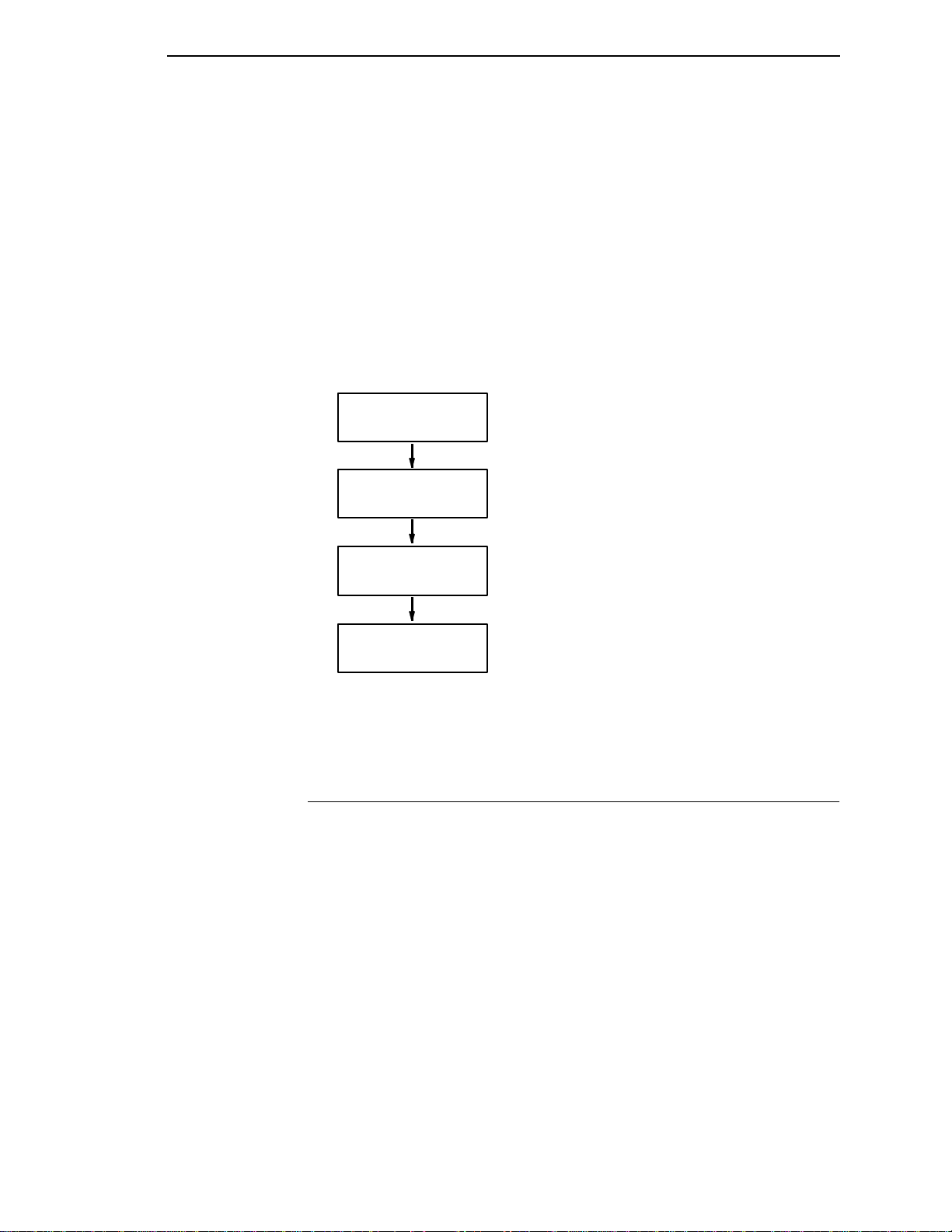
Printer Operating Mode What It Means
Normal Mode
Create Form Mode
Execute Form Mode
Normal Mode
Figure 1
. IGP Modes
Printer receives data
and prints text/graphics.
You send IGP commands
to the printer.
Printer prints the form designed
in Create Form Mode.
Printer returns
to Normal Mode.
Modes of Operation
The IGP has five modes of operation that use specific command sequences
to control the IGP.
• In the Normal Mode, the printer waits for an SFCC in order to perform IGP
functions.
• In Quiet Mode, all IGP commands are ignored except the LISTEN
command.
• In the Create Logo Mode the printer produces graphics such as forms,
logos, bar codes, and alphanumeric data.
• The Execute Mode is the IGP printing mode, which controls when the
actual printing of the bar codes and graphics will occur.
• In Create Form Mode, the printer produces graphics such as forms,
logos, bar codes, and alphanumeric data.
15
Page 16

Chapter 1 The IGP/PGL Emulation
Normal Mode
Normal Mode commands print data in a line printer format until a Special
Function Control Code (SFCC) is detected.
Commands accessible in the Normal Mode are summarized in Table 1 and
fully described on the referenced page. Some Normal Mode commands can
also be used in other modes: Compressed Print, Expand, Ignore, Select
Format, and Vertical Line Spacing, which are Normal Mode commands, can
also be used in the Execute Form Mode; the Multinational Character Set
command can be used in the Normal or Create Modes. Carriage Return,
Form Feed, Line Feed, EVFU commands, and Paper Slew commands also
operate in the Normal Mode.
Note All IGP commands must be entered in UPPERCASE, and
each command line must be followed immediately by a line
feed (or carriage return with line feed terminator) or a paper
motion command.
Quiet Mode
In this mode, the host processes all data as ASCII characters without any IGP
interpretation — the IGP is disabled and all IGP commands are ignored. The
IGP looks only for the (cc)LISTEN command.
16
Page 17
Modes of Operation
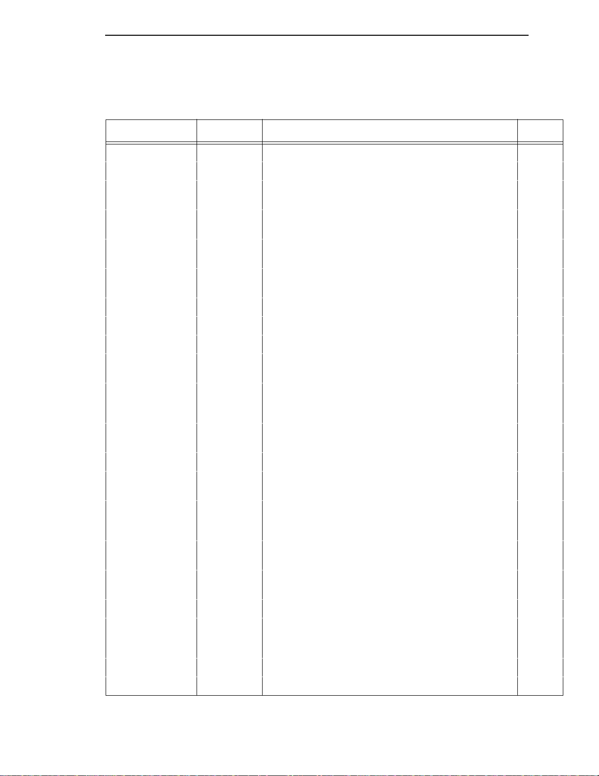
Table 1. Normal Mode Commands
Command Mnemonic Description Page #
Compressed Print DENSITY Defines the horizontal print density in characters per inch (cpi). 45
Configuration CONFIG Reconfigures IGP/PGL parameters 46
Create CREATE Places the IGP in the Create Form Mode where all the Create
Form Mode commands are available to design form elements.
Create Logo LOGO Places the IGP in the Create Logo Mode, where logos can be
defined using the appropriate dot placements.
Delete Form DELETE
FORM
Directory DIRECTORY Provides a li st of all d efined for ms and lo gos, log o assign ments
Emulation Switch EMULATION Switch emulation from IGP/PGL to IGP/VGL (if VGL is present) 57
Execute EXECUTE Executes a previously created form. 58
Expanded Print EXPAND Expands fonts vertically and horizontally. 68
Font FONT Selects a specific typeface: bold, slant (italic) factor, and
Ignore Sequence
On/Off
Line Spacing,
Vertical
Listen LISTEN Removes IGP from the quiet state and enables IGP operation. 74
IGON
IGOFF
LPI Defines the lines per inch (lpi) printing format. 71
Deletes a selected form name from the directory and IGP
memory.
to forms, and memory usage and availability.
symbol set.
Enables the IGP to ignore all characters after the Ignore
Sequence On command is sent until the Ignore Sequence Off
command is sent. See note on page 20.
51
76
52
53
69
71
Multinational
Character Set
Normal Mode NORMAL Places the IGP in the Normal Mode, where it does not change
Paper Instruction
Enable/Disable
Paper Instruction
On/Off for Data Bit 8
Print File PRINT Prints a file from the flash memory. 80
Quiet QUIET IGP operation is disabled until a Listen command is received.
Recall RECALL Recalls forms or logos from memory stored in “setup.ptx”. 81
Reset RESET Deletes all forms and logos from the IGP memory. 82
ISET
USET
EN-PI
DIS-PI
PION
PIOFF
Use a character set.
Create a custom user-defined character set.
the data stream but awaits the SFCC followed by an IGP
command.
Enables or disables use of the PI line with a parallel interface. 80
Enables or dis ables Da ta Bit 8 as the paper i nstruc tion sig nal in
a serial interface.
Any data sent to the line matrix printer emulation is unaffected
by IGP commands.
Chap. 5
78
79
81
17
Page 18
Chapter 1 The IGP/PGL Emulation
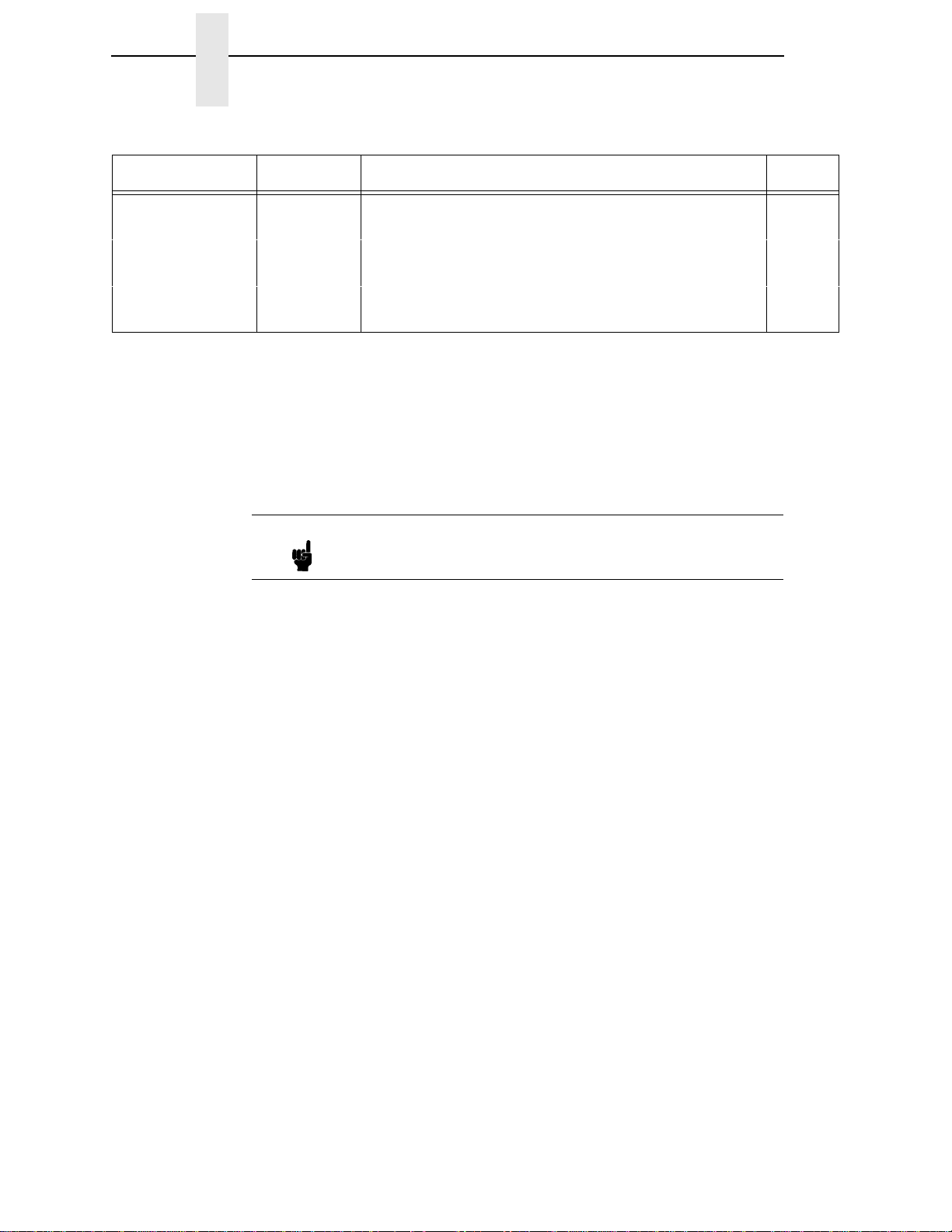
Table 1. Normal Mode Commands (continued)
Command Mnemonic Description Page #
Special Fu nction
Control Code
Select Format
On/Off
Set Up SETUP Automatically executes and loads the IGP/PGL commands into
SFCC Changes the current Special Function Control Code (SFCC). 86
SFON
SFOFF
Ignores all host-generated paper movement commands. See
note on page 20.
the printer at power-up or after a RESET command is sent.
Create Form Mode
Create Form Mode commands design forms, all form components, and bar
codes. The forms are not printed in the Create Form Mode; forms are printed
in the Execute Form Mode after all form design is completed. To begin form
design, access the Create Form Mode using the Create command. The
Create command is always used to enter the Create Form Mode to begin form
design.
Note The CREATE command must be entered in UPPERCASE.
Each element has its own specific set of commands and parameters that
determine size, location, and content. Listed in alphabetical order, Create
Form Mode commands are summarized in Table 2 and fully described on the
referenced pages.
84
85
Print Boundaries
Print area boundaries exist for the paper size selected. All Create Form Mode
commands require you to identify the location for the components in your
form. Boundary checking for form elements is performed only when the form
length is specified. This ensures that forms can be created regardless of the
type of paper you have loaded or margins you have set.
The IGP checks the boundaries before the form is executed to ensure that it
will fit on the loaded paper size. If the debug option is used in the create
statement, the boundaries are checked against the current paper size. Refer
to Appendix C for more information regarding page boundary guidelines.
Create Logo Mode
The Create Logo Mode is used in the Create Form Mode. The Create Logo
Mode creates a logo design; this predefined logo is then “called” into a form in
the Create Form Mode. (The logo must be defined before it is “called”.)
18
Page 19
Modes of Operation
Table 2. Create Form Mode Commands
Command Mnemonic Description Page #
Alphanumerics ALPHA Defines si ze, lo cation, and content of alphanumeric cha rac ters
and dynamic alphanumeric data fields.
Alpha, Incremental ALPHA Defines starting data and increment amount for fixed auto-
increment fields.
Bar Codes BARCODE Each bar code type has its own command to define size,
location, orientation, and data as described in the “Bar Codes”
chapter.
Boxes BOX Defines size, location, and thickness of boxes. 43
Corners CORNER Defines vertical and horizontal length, location, and thickness
of a set of four corners.
Duplication,
Horizontal
End END Terminates the Create Form Mode. 57
Form Length LFORM Specifies the form length by total number of lines at 6 or 8 lpi. 70
Ignore Sequence
On/Off
Lines, Horizontal HORZ Defines the location, size, and thickness of horizontal lines. 72
Lines, Vertical VERT Defines the location, size, and thickness of vertical lines. 73
HDUP Defines the number of horizontal duplications of an element
and the spacing between duplications.
IGON
IGOFF
Enables the IGP to ignore all characters after the Ignore
Sequence On command is sent until the Ignore Sequence Off
command is sent. See Note on page 20.
29
34
Chap. 3
49
54
71
Logo Call LOGO Specifies the location of a previously defined logo. 74
Multinational
Character Set
Page Number PAGE Defines the location for automatically incremented page
Reverse Print REVERSE Defines the location for white-on-black printing and selec ts the
Scale SCALE Defines the vertical spacing and horizontal pitch for data
Select Format
On/Off
ISET Selects one of the mul tinational or international character sets. Chap. 5
78
numbers.
82
background shade.
83
positioning in character or dot columns and rows.
SFON
SFOFF
Ignores all host-generated paper movement commands. See
note on page 20.
84
19
Page 20
Chapter 1 The IGP/PGL Emulation
Execute Form Mode
The Execute Form Mode prints forms created in the Create Form Mode.
Execute Form Mode commands are summarized in Table 3 and fully
described on the referenced pages. Carriage Return, Form Feed, and Line
Feed commands also operate in the Execute Form Mode. The EXECUTE
must
Form command
or a line containing overlay data must separate an EXECUTE command from
a NORMAL command.
Note Some systems pad the data stream with characters and
be entered in UPPERCASE, and a single line spacing
spaces. If the IGP file on your system contains padded
characters or spaces before the SFCC, this data must be
ignored before the IGP can operate. The Ignore Sequence
(IGON/IGOFF) command, discussed on page 71, is
provided for this purpose. At times you may also need the
IGP to ignore host-originated paper movement commands
(carriage return, line feed, form feed, etc.) in lengthy data
streams. Select Format (SFON/SFOFF) discussed on page
84 is provided for this purpose. In addition, the Quiet
command, page 81, can be used to pass data unchanged to
the printer.
20
Page 21
Modes of Operation
Table 3. Execute Form Mode Commands
Command Mnemonic Description Page #
Compressed Print DENSITY Defines the horizontal print density in characters per inch (cpi). 45
Dynamic
Alphanumeric Data
Dynamic Bar Code
Data
Expanded Print EXPAND Expands fonts vertically and horizontally. 6 8
Font FONT Selects a specific typeface: bold, slant (italic) factor, and
Ignore Sequence
On/Off
Incremental
Alphanumeric
Dynamic Data
Increment al Bar
Code Dynamic Data
Line Spacing,
Vertical
Multinational
Character Set
Normal Mode NORMAL Places the IGP in the Normal Mode, where it does not change
n
AF
BF
n
IGON
IGOFF
n
IAF
IBF
n
LPI Defines the lines per inch (lpi) printing format. 71
ISET Selects one of the mul tinational or international character sets. Chap. 5
Executes the dynamic alphanumeric data provided after the
(cc) EXECUTE command.
Executes the dynamic bar code data provided after the (cc)
EXECUTE command.
symbol set.
Enables the IGP to ignore all characters after the Ignore
Sequence On command is sent until the Ignore Sequence Off
command is sent.
Executes the increm ental dyna mic alphan umeric data provided
after the (cc) EXECUTE command.
Executes the incremental dynamic bar code data provided
after the (cc) EXECUTE command.
the data stream but awaits the SFCC followed by an IGP
command.
62
63
69
71
65
65
78
Reset RESET Deletes all forms and logos from the IGP memory. 82
Select Format
On/Off
SFCC SFCC Changes the current Special Function Control Code (SFCC). 86
SFON
SFOFF
Ignores all host-generated paper movement commands. See
note on page 20.
84
21
Page 22

Chapter 1 The IGP/PGL Emulation
Alphanumeric Data
Based on the requirements of a specific application, you can use one of three
methods to print alphanumeric data on a form: Fixed data, Overlay data, and
Dynamic data. These methods are described in more detail in Chapter 2.
• Fixed data prints on each form in the same “prepositioned” location,
unless the location changes in the form definition. Company name,
address, logo, and phone number are typical examples of alphanumeric
data that can be “fixed” onto the form.
• Overlay data is variable alphanumeric data positioned on the page with
line feeds and spaces to fit into exact locations. For example, specific
data can be “overlayed” onto a blank form as if you were typing data into
the appropriate blanks on a preprinted form. Customer names,
addresses, and order numbers are examples of data overlayed onto a
form.
• Dynamic data is variable data entered into specific locations on each
form. Each time the form prints, a command enters new data in those
locations. Customer names, addresses, or any type of variable
alphanumeric or bar code data can be provided dynamically.
Incremental Data
The incremental data feature allows you to update alphanumeric and bar
code data fields in an alphabetical or numeric manner automatically with just
one set of data sent from the host computer.
Alphanumeric and bar code incremental fields can be used with fixed (static)
data input as part of the Create Form Mode or with dynamic data supplied in
the Execute Form Mode.
The incremental fields can be increased or decreased, repeated at specified
intervals before updating, and reset to the starting value after a specified
number of increments.
22
Page 23

2 Commands
IGP Command Standards
IGP commands have many options and a specific format that you must follow
to obtain the desired results. Certain elements are standard for all IGP
commands. These command standards are described in the following
sections. Familiarize yourself with the meaning and use of these standards
before operating the IGP.
Special Function Control Code (SFCC)
The SFCC identifies a command directed to the IGP to enable a specific IGP
function. Based on the host computer interface requirements, various
characters can be selected as the SFCC, such as the caret (^) or a tilde (~).
Do not use a nonprintable character as your SFCC.
It is appropriate to place the SFCC command at the beginning of a new line. If
the SFCC command is placed anywhere else on the line, at the user’s
discretion, the data preceding the command will either print or be ignored,
depending on how the Skip Command Prefix parameter is set.
The examples in this manual use the tilde as the SFCC; always substitute the
actual SFCC required by your system where the tilde is shown. In the general
command formats, the SFCC is represented by (cc).
Semicolon (;)
Each parameter (alpha data, options, etc) on the command line is separated
by a semicolon. Blank spaces between the semicolon and the next parameter
are not allowed. A missing or misplaced semicolon causes an error message.
Uppercase
The IGP/PGL is “case sensitive.” ALL commands must be entered in
uppercase.
Inline Commands
The SFCC, usually a tilde, is suggested to be the first character on a new line.
It may appear anywhere on the command line. There is a configuration option
that determines whether any data preceding a command is printed or is
ignored.
23
Page 24

Chapter 2 IGP Command Standards
All IGP commands begin with the Special Function Control Code (SFCC) and
must end with a line terminator.
Line Terminator
Each command line must be terminated by a line feed (or a carriage return
with a line feed), or a paper motion command. The command line will not be
accepted if not properly terminated. Refer to the system controls for your
system keyboard and printer configuration codes to determine which key(s)
(such as ENTER, LINE FEED, FORM FEED, etc.) perform a line feed,
carriage return with line feed, or form feed function.
Printable Character
To print, alphanumeric and bar code data must be enclosed by a printable
character (a delimiter). This delimiter is represented by
format. In this manual, an asterisk (*) is used in most examples as the
printable character. (The parentheses are
character can be used as this delimiter except a slash (/) or the SFCC. The
same printable character must be used at both the beginning and end of the
text to be printed and can not be used within the text.
(D)
in the command
not
entered.) Any printab le
Spaces
Spaces are used in the general command formats to visually separate
individual command parameters. Supply the appropriate information for the
command parameter, but do not enter the spaces in the command sequence;
they are shown simply as a visual aid to illustrate where one command
parameter ends and another begins.
Command Parameters
Most commands include a number of parameters. Some are optional, and
some are required. Each parameter must be separated by a semicolon (;)
unless noted otherwise. Throughout this manual, actual commands required
for input are shown exactly as they must be entered and all parameters
associated with that command are shown in italics. Optional parameters are
enclosed in brackets [ ], but do not enter the brackets.
Parentheses indicate variable data. You have a choice of what to enter, but
you must enter something. Do not enter the parentheses by themselves.
Form Name
You must use alphanumeric characters to identify the document (form or logo)
you are creating (a maximum of 15 alphanumeric characters). The Form
Name is also used to identify the form during the Execute Form Mode. The
valid Form Name characters are listed in Table 4 and also apply to Logo
Name. The SFCC can also be used in the Form Name. No spaces are
allowed between any of the Form Name characters.
24
Page 25

Prompt
Table 4. Valid Form Name Characters
A through Z (upper and lowercase) Left and right parenthesis ( )
0 through 9 Tilde ~
Dollar sign $ Single quotes ‘ ’
Percent sign % Exclamation point !
Dash — Pound sign #
At sign @ Ampersand &
Left and right braces { }
Prompt
The prompt is the symbol (e.g., a dollar sign, period, or greater than symbol)
used to indicate that the host computer is ready for data input. In this manual,
the prompt is shown as a period (.).
Numeric Values
In this manual, a lowercase n in the command represents a numeric value. If
n
a command parameter includes a lowercase
appropriate numeric value. If the lowercase
and the option is not selected, a value for
, it must be substituted with an
n
is part of an optional parameter
n
is not required.
Comments in Command Lines
To aid in preparation or maintenance of a form or logo, comments can be
added to many command lines. Comments must be preceded by a slash (/).
However, do not use the /comment feature on lines containing an SFCC (i.e.,
CREATE, NORMAL, EXECUTE, etc.). Throughout this manual, comments
are provided in parentheses beside most command lines for better
understanding of IGP operation but should not be included in your IGP files.
Storing Data
To send data to the IGP, use a system command, such as PRINT. (Entering
data through the keyboard does not store data in memory.) Once stored in
memory, the data remains until deleted, the IGP is reset with RESET
command, or until the printer is turned off.
IGP/PGL files can be permanently stored to, deleted from, and retrieved from
the printer’s flash memory by ending CREATE, CREATE LOGO, DELETE
FORM, DELETE LOGO, EXECUTE, and DIRECTORY commands with
;DISK.
For example, the following command creates a form named ORDER and
stores it on the flash memory:
(cc)CREATE;ORDER;DISK
Executing a form or calling a logo will access the default flash automatically if
the object is not found in memory.
25
Page 26
Chapter 2 IGP Command Standards
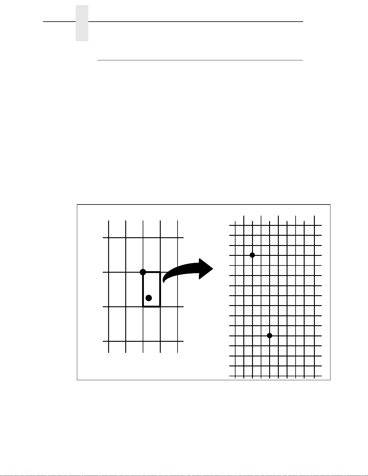
Character Position.Dot Position (CP.DP) Format
The CP.DP format is a special parameter available with the IGP commands.
CP.DP format allows two elements plotted at nearly the same character
location to be offset to eliminate overlapping. Specifying starting and ending
rows and columns is its most frequent use.
Each character location is a cell. Each cell is a grid 12 dot rows high by 6 dot
columns wide (printing at 6 lpi and 10 cpi). The CP.DP format allows a
character cell position (CP) and a specific dot position (DP) within the cell to
be identified as shown in Figure 2. The DP portion of the CP.DP format
specifies a location down (in reference to rows) and to the right (in reference
to columns) within the character cell position.
For example, refer to Figure 2. Suppose a line runs along character position
column 13 (CP = 13). At the same time, an alphanumeric string must begin in
column 13. With CP.DP format, the alphanumeric string can be offset 2 dot
positions (DP = 2) in column 13 to avoid overlap. Specify 13.2 (CP = 13, DP=
.2) for the starting column of the alphanumeric string. Similarly, to place a
horizontal line 8 dot rows beneath another horizontal line in character row
position 11, specify row 11 for one line and row 11.8 for the other line.
10.0
11.0
12.0
13.0
11.0 12.0
15.013.0 14.0
10.9
10.10
10.11
11.0
11.1
11.2
11.3
11.4
11.5
11.6
11.7
11.8
11.9
11.10
11.11
12.0
12.5
12.4
13.0
13.1
13.2
13.3
13.4
13.5
14.1
14.0
26
Figure 2
. CP.DP Format Example
Page 27

Command Codes
Data Fields for Alphanumeric and Incremental Data
Based on the requirements of a specific application, three methods are used
to print alphanumeric data on the form: fixed (or prepositioned) data, overlay
data, and dynamic data.
Fixed Data
Fixed data is entered during the Create Form mode as part of the form
definition. It appears as prepositioned information similar to other form
elements. The fixed data is printed on each form in the same location and can
only be changed by changing the form definition. Your company name,
address, logo, or phone number are typical examples of alphanumeric data
that can be fixed onto the form.
Overlay Data
Data Fields for Alphanumeric and Inc remental Data
Overlay data is variable alphanumeric data entered during the Execute Form
mode by positioning the information with line feeds and spaces into an exact
location. In general, a page of data is overlayed onto a form similar to typing
data in the appropriate blanks of a preprinted form. Each page of overlay data
is separated by form feeds to correspond to each form printed. Customer
names, addresses, and order numbers are examples of variable data that can
be overlayed onto the form.
Dynamic Data
Dynamic data is variable data entered by command during the Execute Form
mode. The dynamic data is entered into a location previously defined in the
Create Form mode. Any number of locations can be identified during the
Create Form mode as part of the form definition. A command during the
Execute Form mode enters new data in the identified location(s) each time
the form prints. Dynamic data is the most efficient method of supplying
variable data to the form. Again, customer names, addresses, or any type of
variable alphanumeric or bar code data can be provided dynamically.
Incremental Data Fields
The incremental data fields feature allows alphanumeric (and bar code) data
fields to automatically update numerically or alphabetically with just one set of
data sent from the host computer. A maximum of 65,535 forms can print with
incremental fields automatically updated. Alphanumeric incremental fields can
be used with fixed (static) data input as part of the Create Form mode or with
dynamic data supplied in the Execute Form mode. Incremental data fields
cannot be used with Overlay data.
27
Page 28
Chapter 2 Command Codes
Dark Printing
A DARK parameter, available in the Alpha, Reverse, and Bar Code
commands, is a double-strike feature which produces bolder, darker text,
denser black backgrounds for reverse print, and extra-dark, more readable
bar codes.
A DARK parameter used with alphanumeric text in the ALPHA command will
print using a bold font.
The extra darkness provided by the DARK parameter improves the Print
Contrast Ratio (PCR) and effectively extends the life of the ribbon. For bar
codes, the PCR describes the difference in light reflection between the bars
and spaces as a measurement of light/dark contrast in order to judge when a
printed bar code will not be dark enough to be read with accuracy by a
scanner. The extra dots used to produce the darker bar code do not change
the overall width of the wide bars. Figure 3 illustrates how the DARK
parameter adds two extra dot columns to wide bar code bars without
increasing bar width.
Due to the second hammer bank stroke required to plot the extra columns of
dots, print speed may be reduced up to half when the DARK parameter is
used with Bar Code commands. However, this decreased print speed should
be weighed against the significant increase in bar code PCR and extended
ribbon life.
NORMAL MODE
Figure 3
ADDED COLUMNS OF DOTS
DARK MODE
. Dark Printing
28
Page 29
Alphanumerics
Alphanumerics
Purpose Defines and positions alphanumeric data on a form as a
“preprinted” static data field or as a dynamic data field.
Mode CREATE
Format ALPHA
n
;] [AF
n;L;
] [
DIR
[R;] [E;] [C
n;
or HSDn;]
[HS
STOP
ALPHA The Alphanumeric command; enter ALPHA.
R The optional reverse printing (white on black)
SR; SC; VE; HE; (D)text(D)
parameter. Enter R to specify a black background.
;] [UC;] [DARK;] [POINT;]
Note The
ignored. In addition, the L parameter, also used in earlier
IGP/PGL versions to specify a long reverse field for
descending characters in dynamic alphanumeric data, is
provided automatically. The IGP/PGL will ignore these
parameters if found in a command line.
E The optional elongated character parameter. Enter
n
C
n;L
AF
D parameter, used in earlier IGP/PGL versions, is
E to specify elongated character printing.
Elongated characters are double height and single
width. If used, the VE and HE parameters must be
7set to 0, or an error message will result. Elongated
character printing is also available with rotated
alphanumerics.
The optional horizontal compres s ion param ete r.
n
Enter C and replace
to specify the number of horizontal characters per
inch (cpi). 10 cpi is the default value. 10A = 10 cpi
OCR-A. 10B = 10 cpi OCR-B. If used, the
HE
parameters must be set to 0, or an error
message will result.
The optional dynamic data field parameters for
identifying the alphanumeric string location on a
form and for designating the length of the
alphanumeric string. If these parameters are used,
the actual text can not be entered during the Create
Form mode; it must be entered dynamically during
the Execute Form mode. Dynamically entering data
during the Execute Form mode permits changes to
the alphanumeric text without redefining or recreating the form. To use this field, perform the
following steps:
with 10, 12, 13, 15, 17 or 20
VE
and
a. Enter AF.
n
b. Replace
through 512 to identify the alphanumeric string
with a number ranging from 1
29
Page 30

Chapter 2 Command Codes
DIR
SR
location on the form. The
parameters specify the exact location of the
alphanumeric field identified by
L
c. Replace
of characters in the dynamic alphanumeric
string ranging from 1 through 512.
d. Dynamically enter the alphanumeric string
itself in the Execute Form mode. The length of
the alphanumeric string must be equal to or
less than the value assigned to the length (
parameter. Refer to “Execute Form: Dynamic
Alphanumeric Data” on page 62.
e. If the dynamic data field is used, do
the ASCII TEXT parameter.
Optional parameter for rotating a character string.
Use the following codes to indicate the direction of
character rotation:
a. Enter CW for 90 degree clockwise rotation.
with a number equal to the number
and SC
n
.
not
L
enter
)
b. Enter CCW for 90 degree counterclockwise
rotation.
c. Enter INV for inverted characters (180 degree
rotation).
The default orientation prints character strings in
the standard horizontal format.
UC Enter UC to specify uppercase-only characters.
When uppercase-only is specified, all lowercase
alpha character codes are converted automatically
to uppercase. Consequently, do not specify
uppercase-only characters if lowercase characters
are required.
DARK Optional parameter to produce bolder text. Enter
DARK or D. (D is also allowed in the ALPHA
command only.) More information about dark
printing is provided on page 28.
SR
SC
Defines the starting row of the alphanumeric data.
Enter a value ranging from row 1 through one less
than the length of the form. Character row or dot
row is specified based on the Scale command
(page 83), or use the CP.DP format (page 26).
Defines the starting column of the alphanumeric
data. Enter a value ranging from column 1 through
one less than the width of the form. Character
column or dot column is specified based on the
Scale command (page 83), or use the CP.DP
format (page 26).
30
Page 31

Alphanumerics
POINT Optional parameter that changes the units for the
vertical and horizontal expansion values. When the
VE
point parameter is present the
font height in 1/72 of an inch (i.e. points). If the
value is non-zero, it defines the character width in
1/72 of an inch, otherwise the character width is the
standard width for the chosen height. Cannot be
used with elongated (E) and compressed (C
parameters.
n
or HSDn Horizontal Spacing. The value n indicates the
HS
number of extra dots to add between each
character.
HS = the value is in 60 DPI dots
HSD = the value is in printer dots.
value define s the
HE
n
)
VE
HE
(D)
text
Defines the vertical expansion factor to enlarge
characters vertically. Enter a value between 0 and
113. Zero specifies the standard font (no
VE
expansion). A
Elongated (E) and compressed (C
cannot be used with a vertical expansion other than
zero.
Defines the horizontal expansion factor to enlarge
characters horizontally. Enter a value between 0
and 113. Zero specifies the standard font (no
expansion). An
Elongated (E) and compressed (C
cannot be used with a horizontal expansion other
than zero.
The printable character (quotation marks for
example) identifying the start and finish of the
alphanumeric string. Enter any printable character
other than a slash (/), the SFCC, or a character
used within the alphanumeric string itself. You must
use the same character at both ends of the
alphanumeric string, but it will not print with the
data.
The group of ASCII characters (the alphanumeric
string) to print. Enter any of the standard ASCII
printable characters (except the character used to
delimit the string in the D parameter). The data
appears as “prepositioned” information on the form
beginning at the location specified by
This is the “fixed” or static alphanumeric data; once
defined on the form, it is changed only by redefining
the form using the Alphanumeric command.
value must be entered.
n
) characters
HE
value must be entered.
n
) characters
SR
and SC.
STOP Stop indicates the end of the Alphanumeric
command; enter STOP, and the IGP will wait for a
new command. If not entered, the IGP will wait for
another set of Alphanumeric command parameters.
31
Page 32

Chapter 2 Command Codes
Comments As dynamic data, the location of the alphanumeric field is
established in the Create Form mode and the actual
alphanumeric data is continuously redefined before placement on
the form in the Execute Form mode. You can also rotate and
reverse print the alphanumeric string using this command.
Example The following program and example in Figure 4 illustrates the
Alphanumeric command capabilities. To illustrate positioning,
starting row and column are indicated on the example but do not
necessarily reflect actual location on the page. Notice the same
starting row is used for all “EXAMPLE” characters, and they are
all aligned on the same baseline (or bottom), regardless of
expanded or compressed parameters. The string rotates around
the point of intersection of the starting row and columns shown by
the “pinwheel” E. A rotated 10 cpi character establishes the
baseline for all character sizes.
~CREATE;TEST
ALPHA
36;37;4;4;*E*
36;41;2;3;*X*
36;44;2;2;*A*
36;46;1;1;*M*
C13;36;47;0;0;*P*
C15;36;48;0;0;*L*
C17;36;49;0;0;*E*
CW;36;60;2;2;*CLOCK*
CW;42;60;4;4;*WISE*
CCW;58;26;2;3;*COUNTER*
CCW;45;26;2;2;*CLOCK*
CCW;39.2;26;1;1;*WISE*
INV;54.5;58;0;0;*INVERTED*
R;INV;54.5;49;0;0;*REVERSE PRINT*
45;48;0;0;*E*
CW;UC;45;48;0;0;*E*
CCW;45;48;0;0;*E*
INV;45;48;0;0;*E*
STOP
END
~EXECUTE;TEST
32
~NORMAL
Page 33

ROW 36
Alphanumerics
ROW 39.2
ROW 58
COLUMN 37 COLUMN 49
COLUMN 48
ROW 45
COLUMN 60
ROW 54.5
COLUMN 58
COLUMN 26
Figure 4
. Alphanumeric Example
33
Page 34

Chapter 2 Command Codes
Alphanumerics, Incremental Fields
Purpose The incremental fields feature updates alphanumeric (and bar
code) data fields in a numeric or alphabetical manner
automatically using just one set of data sent from the host
computer. Incremental alphanumeric data fields can be applied to
fixed (static) data (page 38), or dynamic data (page 40).
Mode CREATE (for fixed data) or EXECUTE (for dynamic data)
Note Throughout the discussion of incremental fields, the term
Comments Incremental fields can increase or decrease, repeat at specified
intervals before updating, and reset to the starting value after a
specified number of increments. A maximum of 65,535 fields can
print.
“increment” or “incremental” means the field is automatically
updated by a specified amount (or increment). The field can
actually be increased/decreased in sp ecified
increments/dec re men ts with in the co mma nd.
Using Incremental Alphanumeric Data
Incrementing is controlled with the STEPMASK and STARTDATA command
parameters as described in Table 5. The parameters are part of the
Incremental Alphanumeric Fixed Data command or part of the Execute
command when using incremental alphanumeric dynamic data.
The STEPMASK parameter performs the following three functions:
1. Defines the increment amount (step);
2. Defines the number of characters allowed in the data field (STARTDATA);
and
3. Provides a “mask” to link or unlink subfields of the data to be incremented
independently. The data provided in the STEPMASK field combined with
the data in the STARTDATA field determine the result of these functions.
The increment amount is defined by the numeric value of the STEPMASK
data. For example, a STEPMASK value of 1 increments the STARTDATA by
1; a STEPMASK value of 2 increments the STARTDATA by 2.
The maximum number of characters allowed in the STARTDATA field is
defined by the number of characters in the STEPMASK field; the
STARTDATA field cannot contain more characters than used in the
STEPMASK field.
34
Page 35

Alphanumerics, Incremental Fields
Linked and unlinked masking of subfields within the STARTDATA is defined
by the L value in the STEPMASK field. L indicates linked but non-incremental
data in the corresponding position of the STARTDATA field; any alpha
character other than L in the STEPMASK field indicates a non-incremental,
non-linked STARTDATA subfield.
Table 5. Increment Alphanumeric
STEPMASK START DATA Character Type and Function
0 - 9 A - Z Alpha characters incremented by
amount in STEPMASK field
0 - 9 0 - 9 Numeric characters incremented
by amount in STEPMASK field
0 - 9 Space Same character type as character
in the next right adjacent, linked
increment position. Character
type will be numeric if in least
significant position.
0 - 9 Not A - Z or 0 - 9 Error
Not 0 - 9 or L Any Non-incrementing alphanumeric
character
L Any Linked, non-incrementing
alphanumeric character
The examples on the following pages illustrate incremental alphanumeric data
fields. All cases in the examples use a repeat count parameter value of 1 and
a reset count parameter value of 0. The three vertical dots illustrate the
natural progression for each column and unit of data based on the
incremental count and its impact on linked and unlinked data fields.
35
Page 36

Chapter 2 Command Codes
Value Description
ST ARTDATA:
STEPMASK:
Printed Results:
STARTDAT A:
STEPMASK:
Printed Results:
ABC123
000001
Linked subfields: ABC and 123
RPT = 1
RST = 0
ABC123
ABC124
......
......
......
ABC999
ABD000
......
......
......
ZZZ999
AAA000
Value Description
1ABC123
0LLL001
Two separate but linked numeric
subfields: 1 and 123, while fixed data
ABC is nonincrementing
1ABC123
1ABC124
. ...
. ...
. ...
1ABC999
2ABC000
RPT = 1
RPT = 0
36
STARTDATA:
STEPMASK:
Printed Results:
Value Description
ABC123
001XX1
ABC123
ABD124
. .
. .
. .
ABI129
ABJ120
T wo separate unlinked subfields:
ABC and 3, while fixed data 1 and 2
is nonincrementing
RPT = 1
RPT = 0
Page 37

Alphanumerics, Incremental Fields
Value Description
ST ARTDATA:
STEPMASK:
Printed Results:
STARTDAT A:
STEPMASK:
Printed Results:
STARTDATA:
STEPMASK:
Printed Results:
___1
0001
Single numeric field with leading
spaces (_)
RPT = 1
___1
___2
....
....
....
__10
Value Description
_AA98
0LL01
RPT = 0
Two separate but linked numeric
subfields: AA and 98, with leading
space (_); fixed data AA is
_AA98
. .
. .
. .
1AA00
Value Description
_42AR
0LL01
nonincrementing
RPT = 1
RST = 0
Two separate but linked alpha
subfields: A and R, with leading
space (_); fixed data 42 is
_42AR
_42AS
. ..
. ..
. ..
_42ZZ
A42AA
nonincrementing
RPT = 1
RST = 0
STARTDATA:
STEPMASK:
Printed Results:
Value Description
9AA02
-XXX01
9AA02
9AA01
9AA00
9AA99
..
..
..
9AA03
Single numeric field decremented by
1, while fixed data 9 and AA are
nonincrementing.
37
Page 38

Chapter 2 Command Codes
Alphanumerics, Incremental: Fix ed Data Fie lds
Purpose To automatically increment/decrement fixed alphanumeric data
fields.
Mode CREATE
Note In the command format below, incremental alphanumeric
command parameters are shown in boldface type.
Standard alphanumeric command parameters and optional
nonincremental parameters are shown in
described in the Alphanumerics section (starting on page
29). Due to space constraints, the command parameters are
separated into two lines. During actual IGP inp ut, DO NOT
separate command parameters.
italics
and are
Format
ALPHA
I;
[R;] [E;] [Cn;]
SR; SC; VE; HE;
[DIR;] [UC;] [DARK;] [POINT;] [HSn or HSDn;]
[
idir] STEPMASK
; [RPTn;] [RSTn;]
(D)STARTDATA(D)
STOP
I Identifies this alphanumeric command as an
Incremental Alphanumeric command; enter I.
idir
STEPMASK
n
RPT
The optional increment direction parameter to
specify an increment (add) or decrement (subtract)
to the data. Enter a plus sign (+) or leave the field
blank to increment (the default). Enter a minus sign
(-) to decrement.
Defines the increment amount (step), the number
of character positions in the data field, and provides
a mask to control the increment function on specific
parts of the data. Refer to Table 5 on page 35 for
complete information on STEPMASK parameter
values.
The optional incremental repeat count parameter to
specify the number of times a particular field value
is repeated before it is incremented. A repeated
field value is useful when printing multiple
rows/columns of identical labels before increasing
to the next value.
To use the repeat count parameter, enter RPT and
n
replace
65,535 to specify the repeat count. The default
repeat count parameter is 1, which will increment
the field value each time it prints.
with a numeric value ranging from 1 to
38
Page 39

RST
Alphanumerics, Incremental: Fixed Data Fields
n
The optional incremental reset count parameter to
specify the number of times an incremented field is
printed (on one or more forms) before it is reset to
the starting value. A reset count is useful when
printing a hierarchy of fields where a low-level field
generates a sequence of numbers, is reset, and the
next higher field level is incremented (such as in a
unit/box/carton application). To use the reset count
n
parameter, enter RST and replace
ranging from 1 to 65,535 to specify the reset count.
The default reset count value is 0.
with a number
STARTDATA
Comments The Incremental Alphanumeric Fixed Data Fields command is a
revised version of the standard IGP alphanumeric command, but
it does not replace the standard alphanumeric command.
~CREATE;TEST;288
VDUP;3;6
ALPHA
I;6;5;4;4;-00001;*12345*
STOP
VDUP;OFF
END
~EXECUTE;TEST
Defines the starting value of the incrementing field.
Enter the appropriate value. Refer to “Using
Incremental Alphanumeric Data” on page 34 for
complete information on STARTDATA and
STEPMASK parameter values.
The maximum amount of STARTDATA charact er s
must be equal to or less than the number of
characters in the STEPMASK field. If the number of
data characters is less than the number used in
STEPMASK, the data will print right justified with
preceding spaces. Characters allowed for
incrementing fields (STEPMASK values of 0 - 9)
are numeric 0 - 9 and alpha A - Z (uppercase only).
Any printable character is allowed in
nonincrementing fields (STEPMASK values not 0 -
9).The STARTDATA must be enclosed within
standard printable character delimiters just as a
standard alphanumeric data field is enclosed within
delimiters.
~NORMAL
39
Page 40

Chapter 2 Command Codes
Alphanumerics, Incremental: Dynamic Da ta Fields
Purpose Automatically increments/decrements dynamic alphanumeric
data fields. Specifies the location and size of the incremental
dynamic data field during the Create Form mode. STEPMASK
and STARTDATA parameters are supplied in the Execute
command during the Execute Form mode.
Mode CREATE
Note In the command format below, incremental alphanumeric
command parameters are shown in boldface type; standard
alphanumeric command parameters and optional
nonincremental parameters are shown in
italics.
Format
ALPHA
[R;] [E;] [Cn;]
IAFn;L;
[DIR;] [UC;] [DARK;] [POINT;]
[HSn or HSDn;]SR; SC; VE; HE STOP
IAFn;L Identifies this alphanumeric command as an
Incremental Alphanumeric Dynamic Data Field
command. The command parameter string
identifies the incremental dynamic data field
location on the form and defines the length of the
alphanumeric data. If these parameters are used,
the STEPMASK and STARTDATA parameters can
not be entered in the Create Form mode; they are
entered dynamically during the Execute Forms
mode. To use the incremental dynamic data field,
perform the following steps:
a. Enter IAF to specify an incremental
alphanumeric dynamic data field.
n
b. Replace
through 512 to identify the alphanumeric string
location on the form. The standard
alphanumeric SR and SC command
parameters specify the exact location of the
field identified by
c. Replace
of characters in the dynamic alphanumeric
string (STARTDATA) ranging from 1 through
280.
d. Dynamically enter the STEPMASK and
STARTDATA parameters in the Execute Form
mode. The length of the data must be equal to
or less than the value assigned to the length
(L) parameter. Refer to “Execute Form:
Incremental Dynamic Data” on page 65 for
more information.
with a number ranging from 1
n
.
L
with a number equal to the number
40
Page 41

Alphanumerics, Incremental: Dynamic Data Fields
Comments The Incremental Alphanumeric Dynamic Data Fields command is
a variation of the standard IGP Alphanumeric command, but does
not replace the standard alphanumeric command.
As with standard dynamic data fields, incremental dynamic data
fields allow the starting data to be changed without changing the
form definition program. Increment parameters can also change
with each new job without changing the form definition program.
Duplicating Incremental Alphanumeric Fields — Incremental
alphanumeric fixed and dynamic data fields are duplicated
horizontally using the HDUP command and vertically using the
standard VDUP command. Duplicated incremental fields
increment in left-to-right, top-to-bottom order. The following
examples illustrate the results of duplicated incremental fields.
STARTDATA:
STEPMASK:
Printed Results:
Page #1:
Page #2:
STARTDATA:
STEPMASK:
STARTDATA:
STEPMASK:
Printed Results:
Value
01
01
01 02 03
04
05
06
07
08
09
10
11
12
Field A
A01
X01
Field B
B01
X01
Description
Single numeric field (01)
RPT = 1
RST = 0
HDUP = 3
VDUP = 2
Unlinked subfields, alpha (A),
numeric (01)
RPT = 3
RST = 9
HDUP = 3
VDUP = 3
Unlinked subfields, alpha (B),
numeric (01)
RPT = 1
RST = 0
(No HDUP or VDUP)
Page #1:
Page #2:
Example The following program will produce the Incremental Alphanumeric
A01 A01 A01 B01
A02
A03
A01 A01 A01 B02
A02
A03
data example shown above. The program elements are also
defined. (Refer to the command format on page 38.)
A02
A03
A02
A03
A02
A03
A02
A03
41
Page 42

Chapter 2 Command Codes
~CREATE;TEST
HDUP;3;6
VDUP;3;1
ALPHA
I;1;1;0;0;001;RPT3;RST9;*A01*
STOP
VDUP;OFF
HDUP;OFF
ALPHA
I;1;18;0;0;001;RPT1;*B01*
STOP
END
~EXECUTE;TEST;2
~NORMAL
where:
I;1;1;0;0;001;RPT3;RST9;*A01*
Incremental alphanumeric command;
SR of 1; SC of 1;
VE and HE are 0;
001 stepmask increments by 1;
RPT3 repeats each field value 3 times;
RST9 prints and increments each field 9 times
before resetting;
*A01* is the starting value.
I;1;18;0;0;001;RPT1;*B01*
~CREATE;TEST;288
VDUP;3;6
ALPHA
IAF1;5;6;5;4;4
STOP
VDUP;OFF
END
~EXECUTE;TEST
~IAF1;+00002;*45678*
~NORMAL
Incremental alphanumeric command;
SR of 1; SC of 18; VE and HE are 0;
001 stepmask increments by 1;
RPT1 repeats each field value once;
RST0 is not used (default value is 0), prints and
increments continuously without resetting;
*B01* is the starting value.
42
Page 43

Boxes
Purpose Produces any variety of rectangular boxes.
Mode CREATE
Format BOX
LT; SR; SC; ER; EC
STOP
BOX The Box command; enter BOX. Boxes expand
down and to the right from the given row and
column.
Boxes
LT
SR
SC
ER
EC
Defines the line thickness, measured in dots. Line
thickness is based on dot dimensions of 1/72 inch
both horizontally and vertically, so that line
thickness is equal in both directions. Enter a value
of 1 or greater.
Defines the starting row of the box. Enter a value
ranging from row 1 through one less than the length
of the form. Character row or dot row is specified
based on the Scale command (page 83), or use the
CP.DP format (page 26).
Defines the starting column of the box. Enter a
value ranging from column 1 through one less than
the width of the form. Character column or dot
column is specified based on the Scale command
(page 83), or use the CP.DP format (page 26).
Defines the ending row of the box. Enter a value
ranging from row 2 through the last row of the form.
The ending row must be greater than the starting
row. Character row or dot row is specified based on
the Scale command (page 83), or use the CP.DP
format (page 26).
Defines the ending column of the box. Enter a
value ranging from column 2 through the last
column of the form. The ending column must be
greater than the starting column. Character column
or dot column is specified based on the Scale
command (page 83), or use the CP.DP format
(page 26).
STOP Stop indicates the end of the Box command; enter
STOP, and the IGP will wait for a new command. If
not entered, the IGP will wait for another set of Box
command parameters.
43
Page 44

Chapter 2 Command Codes
Example The following program and example in Figure 5 defines two
boxes. To illustrate positioning, the starting row and column are
indicated on the example but do not necessarily reflect actual
location on the page. (Note the position of the ending row and
column.)
BOX
3;24;16;51;63 (One box three dot rows thick)
2;44;48;46;58 (One box two dot rows thick)
STOP
COLUMN 16
ROW 24
Figure 5
ROW 44
. Box Example
COLUMN 48
COLUMN 58
COLUMN 63
ROW 46
ROW 51
box.ex
44
Page 45

Compressed Print (Density)
Compressed Prin t (Density)
Purpose Defines the horizontal print density in characters per inch (cpi).
Mode NORMAL, EXECUTE
Format (cc) DENSITY
(cc) The Special Function Control Code.
DENSITY The Density command; enter DENSITY.
n
Comments Print density formats of 10, 12, 13, 15, 17, or 20 cpi are available.
Standard print density is 10 cpi. After a Density command is
entered, all subsequent alphanumerics print at the specified
density until another Density command, a Normal mode
command, or a Reset command is entered. The Density
command also permits the standard printer editing function
(carriage return editing). After the Density command is entered,
data in the print buffer can be edited as described in your printer
;n
Selects the de n si ty i n c pi, OC R-A , or OC R- B ; en t e r
a value of 10, 12, 13, 15, 17, or 20 to specify the
density in characters per inch (the default is 10 cpi),
or 10A to select 10 cpi OCR-A or 10B to select 10
cpi OCR-B.
User’s Guide.
Example The following command selects 15 cpi printing format until
another Density command, a Normal mode command, or a Reset
command is entered.
~DENSITY;15
45
Page 46

Chapter 2 Command Codes
Configuration
Purpose Places the IGP/PGL in the Configuration mode, where changes
to any or all of the IGP/PGL configuration parameters via
software control can be made instead of from the printer control
panel.
Mode NORMAL
Note A separate line is required for the CONFIG command, the
Format (cc)CONFIG
parameter;value
END
(cc) The SFCC.
CONFIG The Configuration command; enter CONFIG.
parameters and values, and the END command.
parameter;value
The parameter for which a configuration change is
desired, and the value associated with that
parameter. The available parameters and the
values associated with these parameters are listed
in Table 6.
END Terminates the CONFIG command; enter END.
Note All CONFIG parameters except RESET must be followed by
a semicolon (;). Any CONFIG parameters not entered in
UPPERCASE and exactly as listed in Table 6 will result in
an Error 156. (Refer to the “Error Codes” chapter.)
46
Page 47

Configuration
Table 6. Configuration Parameters
Configuration Parameter Value
AI 00 SPACES 0 = Disabled; Non-Zero = Enabled
AUTO WRAP 0 = Disabled; Non-Zero = Enabled
CARRIAGE RETURN DEF 0 = Disabled; Non-Zero = Enabled
CR EDIT 0 = Disabled; Non-Zero = Enabled
ERROR REPORT 0 = Off; 1 = On; 2 = Debug
EXT EXECUTE COPY 0 = Disabled; Non-Zero = Enabled
HOST FORM LENGTH 0 = Disabled; Non-Zero = Enabled
IGNORE CHAR 0-255 = the selected ignore char;
any other value = ignore mode off
IGP100 COMPATBL 0 = Disabled; Non-Zero = Enabled
I-2/5 SELECTION 1 = Trailing Spaces
2 = X2DPD
3 = Modulo 7 CD
any other value = Leading Zero
LINE FEED DEF 0 = Disabled; Non-Zero = Enabled
LPI 6, 8, 9 or 10
OPTIMIZED RATIO 0 = Disabled; Non-Zero = Enabled
PRINTER PI LINE 0 = Disabled; Non-Zero = Enabled
SFCC 1-255
SKIP PREFIX 0 = Disabled; Non-Zero = Enabled
SLASH ZERO 0 = Disabled; Non-Zero = Enabled
SLEW RANGE 0 = 15; Non-Zero = 16
SO CHAR 0 = Disabled; Non-Zero = Enabled
TRUE FORM SLEW 0 = Disabled; Non-Zero = Enabled
UPPERCASE 0 = Disabled; Non-Zero = Enabled
POWER ON IGP/PGL 0 = Disabled; Non-Zero = Enabled
UPC DESCENDERS 0 = Disabled; Non-Zero = Enabled
47
Page 48

Chapter 2 Command Codes
Comments The IGP/PGL configuration parameters available are defined in
your
Any or all parameters can be used within one CONFIG
command, and they can be listed in any order. List each
parameter;value
command. Default configuration values can be reset using the
CONFIG command.
Parameters not followed by a value, and parameters followed by
any non-zero value are interpreted as “true” or “enabled” values.
For carriage return and line feed definitions, a zero value does
not change the data stream. However, for non-zero values, a
carriage return character or line feed character will be interpreted
as a carriage return plus a line feed.
Parameters not listed in this command remain unchanged. If a
parameter error is detected for parameters other than 0 or 1 (i.e.,
SFCC, Top/Bottom Margin, Left Margin), the value will default to
the current configuration from disk/flash.
Example 1 The following command enables IGP/PGL Auto Wrap, disables
Auto Eject, and selects 6 lpi printing.
~CONFIG
AUTO WRAP;1
AUTO EJECT;0
LPI;6
END
Example 2 The following command resets all control panel IGP/PGL
configuration parameters back to default values.
~CONFIG
RESET
END
User’s Guide
.
on a separate line, terminating with the END
48
Page 49

Corners
Purpose Defines corner sets.
Mode CREATE
Format CORNER
LT; SR; SC; ER; EC; VL; HL
STOP
CORNER The Corner command; enter CORNER. Corners
expand down and to the right from the given row
and column.
Corners
LT
SR
SC
ER
EC
Defines the line thickness, measured in dots. Line
thickness is based on dot dimensions of 1/72 inch
both horizontally and vertically, so that line
thickness is equal in both directions. Enter a value
of 1 or greater.
Defines the starting row of the corner. Enter a value
ranging from row 1 through one less than the length
of the form. Character row or dot row is specified
based on the Scale command (page 83), or use the
CP.DP format (page 26).
Defines the starting column of the corner. Enter a
value ranging from column 1 through one less than
the width of the form. Character column or dot
column is specified based on the Scale command
(page 83), or use the CP.DP format (page 26).
Defines the ending row of the corner. Enter a value
ranging from row 2 through the last row of the form.
The ending row must be greater than the starting
row. Character row or dot row is specified based on
the Scale command (page 83), or use the CP.DP
format (page 26).
Defines the ending column of the corner. Enter a
value ranging from column 2 through the last
column of the form. The ending column must be
greater than the starting column. Character column
or dot column is specified based on the Scale
command (page 83), or use the CP.DP format
(page 26).
VL
HL
Defines the length of the vertical arm (including the
line thickness) of each corner in the set. Enter a
value of 1 or greater specified in character or dot
rows based on the Scale command (page 83), or
use the CP.DP format (page 26).
Defines the length of the horizontal arm (including
the line thickness) of each corner in the set. Enter a
value of 1 or greater specified in character or dot
columns based on the Scale command (page 83),
or use the CP.DP format (page 26).
49
Page 50

Chapter 2 Command Codes
STOP Stop indicates the end of the CORNER command;
Example The following program specifies a corner set as shown in Figure
6. To illustrate positioning, the starting row and column are
indicated on the example but do not necessarily reflect actual
location on the page. (Note the position of the ending row and
ending column; they do not include the line thickness.)
CORNER
5;27;27;42;55;4;6 (Each corner in the set is 5
STOP dot rows thick, 4 character
enter STOP, and the IGP will wait for a new
command. If not entered, the IGP will wait for
another set of Corner command parameters.
rows high, 6 character columns
wide)
COLUMN 27
ROW 27
Figure 6
HORIZONTAL LENGTH
6 COLUMNS
. Corner Example
VERTICAL
LENGTH
4 ROWS
ROW 42
COLUMN 55
50
Page 51

Create
Create
Purpose Places the IGP in the Create Form mode, where forms and form
elements can be defined using the appropriate commands.
Mode NORMAL
Format (cc)CREATE; [/]
(cc) The Special Function Control Code.
CREATE The Create Form mode command; enter CREATE.
/ The optional debug character to check the program
line by line for incorrect parameters and print
boundaries using the current page size; enter the
slash symbol (/) to debug the program. No checks
are made until the completed program is sent to the
IGP for storage (when the form is executed by
printing the file with the IGP program). Then the
form name is entered into the directory, and the
program is evaluated. If errors are detected, the
program will print, line by line (including the error on
the line where the error occurs), followed by the
error-free sections of the form. Correct all errors
and delete the slash. Refer to “Solving Program
Errors” on page 248.
formname
FL
Defines the form name of the form being created.
The form name should be no more than 15
characters in length. Refer to page 24 for a list of
allowable form name characters. If a form is
created with the same name as a form already
existing in memory, the newly created form will
replace the existing form. All future reference to the
form (editing, executing, or deleting the form from
the directory) must be made using the assigned
name.
The optional forms length parameter to specify the
maximum length of the form. (Form length cannot
exceed the physical length of the page). Specify the
form length in one of three ways:
formname [;FL
] [;DISK]
a. Enter 0 to define a form of unspecified length.
The form will end after the longest element;
that is, the form length is automatically
controlled to contain all elements without extra
length beyond the longest element. This can
be used to eliminate wasted paper after
producing short forms.
b. Enter a value for the form length ranging from
1 through 65,535 to specify the forms length in
dot rows. (12 dot rows per line = 6 lpi spacing;
9 dot rows per line = 8 lpi spacing.)
51
Page 52

Chapter 2 Command Codes
DISK Optional parameter to store the form on the
Example The following command creates a form named ORDER with the
default forms length:
(cc)CREATE;ORDER
Delete Form
Purpose Deletes the form identified by the form name from the directory
and the IGP memory.
Mode NORMAL
c. To specify the default forms length of 792 dot
rows (11 inches at 6 lpi), do not enter a value
in the form length parameter.
printer’s flash memory. Enter DISK.
Format (c c)DELETE FORM;
(cc) The Special Function Control Code.
DELETE FORM
formname
DISK Optional parameter to delete the form from the
Comments For more information, refer to the Directory Example on page 247
and the Delete Example on page 248.
Example The following command deletes the form named “PAY#” from the
directory, IGP memory, and the printer’s flash memory.
~DELETE FORM;PAY#;DISK
formname
The Delete Form command; enter DELETE FORM.
Identifies the form to be deleted. Enter the name of
the form exactly as it was created. You can delete
an entire form directory by inputting *ALL as the
form name.
flash memory where it was originally stored. Enter
DISK.
[;DISK]
52
Page 53

Delete Logo
Delete Logo
Purpose Deletes the logo identified by the logo name from the directory
and the IGP memory.
Mode NORMAL
Format (cc)DELETE LOGO;
(cc) The Special Function Control Code.
DELETE LOGO
The Delete Form command; enter DELETE LOGO.
logoname
DISK Optional parameter to delete the logo from the flash
Comments Printing a form that contains a deleted logo will produce an error
message. For more information, refer to the Directory Example
and the Delete Example on pages 205 and 207.
Example The following command deletes the logo named “MEMO” from
the directory, IGP memory and the printer’s flash memory.
~DELETE LOGO;MEMO;DISK
Identifies the logo to be deleted. Enter the name of
the logo exactly as it was created. You can delet e
an entire logo directory by inputting *ALL as the
logo name.
memory where it was originally stored. Enter DISK.
logoname
[;DISK]
Directory
Purpose Prints the following information: (1) all defined forms and logos,
(2) logo assignment to forms, and (3) memory usage and
availability.
Mode NORMAL
Format (cc)DIRECTORY [;DISK]
(cc) The Special Function Control Code.
DIRECTORY The Directory command; enter DIRECTORY.
DISK Optional parameter to specify the forms and logos
stored on the flash memory. Enter DISK.
Comments As many forms and logos as printer memory allows may be
stored in IGP memory. If the memory is full, the form will not print;
available space in the memory must be at least the size of the
form being executed.
For more information, refer to the Directory Example on page
247.
53
Page 54

Chapter 2 Command Codes
Duplication, Horizontal
Purpose Defines both the number of times form elements are duplicated
horizontally and the spacing between each duplication.
Mode CREATE
Format HDUP;
elements to be duplicated
HDUP;OFF
HDUP The Horizontal Duplication command; enter HDUP.
dup#
offset#
HDUP;OFF Terminates the Horizontal Duplication command;
dup#; offset#
Specifies number of times the entered form
element(s) will repeat horizontally. Enter a value
ranging from 1 through 512.
Specifies the horizontal offset to establish the
horizontal spacing between each duplication of the
form element(s) specified in the body of the
command. Enter a value in terms of dot or
character columns based on the Scale command
(page 83), or use the CP.DP format (page 26). The
offset is from starting column to starting column.
enter HDUP;OFF. If not entered, the IGP expects
another form element to be defined for duplication.
A single HDUP command can define different types
of elements for duplication.
54
Page 55

COLUMN 10
COLUMN 11
COLUMN 12
COLUMN 13
Duplication, Horizontal
Example The following example is a horizontal duplication of a series of
vertical lines. To illustrate positioning, starting row and column
are indicated on the example but do not necessarily reflect actual
location on the page.
HDUP;14;4 (14 dupes with 4-character column spacing)
VERT (Command to be duplicated horizontally)
1;10;59;59.6 (Note CP.DP format: 59.6)
1;10.3;58.9;59.9
1;11;58.6;60
1;11.3;58.3;60.3
1;12;58;60.6
1;12.3;58.3;60.3
1;13;58.6;60
1;13.3;58.9;59.9
STOP (Terminates the duplicated element command)
HDUP;OFF (Terminates the horizontal duplication)
ROW 58
COLUMN 13.3
COLUMN 12.3
COLUMN 11.3
COLUMN 10.3
DUPLICATING THE SET HORIZONTALLY 14 TIMES
ROW 60.6
hdup.ex
55
Page 56

Chapter 2 Command Codes
Duplication, Vertical
Purpose Defines both the number of times elements are duplicated
vertically and the spacing between each duplication.
Mode CREATE
Format VDUP;
dup#; offset#
elements to be duplicated
VDUP;OFF
VDUP The Vertical Duplication command; enter VDUP.
dup#
Specifies number of times the entered form
element(s) will repeat vertically. Enter a value
ranging from 1 through 512.
offset#
Specifies the vertical offset to establish the vertical
spacing between each duplication of the form
element(s) specified in the body of the command.
Enter a value in terms of dot or character columns
based on the Scale command (page 83), or use the
CP.DP format (page 26). The offset is from starting
row to starting row.
VDUP;OFF Terminates the Vertical Duplication command;
enter VDUP;OFF. If not entered, the IGP expects
another form element to be defined for duplication.
A single VDUP command can define different types
of elements for duplication.
Example The following example is a vertical duplication of one horizontal
line. The line is duplicated three times. To illustrate positioning,
the starting row and column are indicated on the example but do
not necessarily reflect actual location on the page.
VDUP;3;2 (3 duplications with 2-char. row spacing)
HORZ (Command to be duplicated vertically)
1;52;15;65
STOP (Terminates the duplicated element command)
VDUP;OFF (Terminates the vertical duplication)
56
ROW 52
ROW 54
ROW 56
COLUMN 15
COLUMN 65
Page 57

Emulation Switching
Emulation Switching
Purpose To switch the active emulation from PGL to the emulation
selected.
Mode NORMAL
Format (cc)EMULATION;
EMULATION The Emulation Switch command.
emulation
Comments This command is only processed when VGL is included in the
software package. If not, this command is simply ignored. The
switching of emulations causes PGL to perform a soft reset.
Therefore, front panel selections return to their saved state, and
all forms and logos resident in RAM memory are deleted.
emulation
Specifies the emulation to activate. Currently, the
only selection is VGL (Code V). Enter VGL. If VGL
is not the selection, this command is then ignored.
End
Purpose Terminates the current mode of operation and must be used
before entering a new mode command (EXECUTE, LOGO,
NORMAL, or even CREATE).
Mode CREATE
Format END
Comments After the End command is received, the IGP flushes program
errors, stores the error-free portions of the form program just
completed, and then returns to the Normal mode. If the debug
slash (/) is included in the Create command, the program prints
with any corresponding error messages.
57
Page 58

Chapter 2 Command Codes
Execute Form Mode
How to Use the Execute Com mand
Forms are printed in the Execute Form mode. In addition to printing the form
in the Execute Form mode, variable data can also be entered onto the form
“dynamically” during the Execute Form mode. This dynamic data input during
the Execute Form mode includes page numbers, alphanumeric data fields,
and bar code data fields. Pagination, described on page 78, is performed in
the Execute Form mode. Dynamic alphanumeric and bar code data require
additional commands within the Execute Form mode.
The fastest method for repeated forms printing is to use the form feed
character. Rather than sending a series of Execute/Normal commands, which
slows the process by performing an
feed character instructs the IGP to start a new page with new EVFU, dynamic
and overlay data using the existing Execute commands for the form. The
EVFU Data-Dynamic Data-Overlay Data-Form Feed Character
be repeated indefinitely while maintaining the optimum print speed within the
original Execute command.
open-print-close
form sequence, the form
sequence can
Note When a form count is not specified, a single line spacing (or
a line containing overlay data) must always separate an
EXECUTE command from a NORMAL command.
To Execute Forms Rapidly
In order to save reloading time, the IGP remembers the last form executed.
However, a form must be loaded if it was not the last form executed, if it was
used with a CREATE command since the last EXECUTE, or if any logo has
been created.
When the form is found in memory, it is loaded and execution resumes;
otherwise, the “FORM NOT FOUND” error is printed.
Print Formats in the Execute Form Mode
The Execute Form mode has two print formats. The
command format, shown on the next page, is used for executing
nonincremental data and incremental fixed data. An
command format, containing two additional parameters, is used for executing
incremental dynamic data and is discussed on page 65.
During the Execute Form mode, the IGP responds to regular print format
commands such as 8 lpi, and elongated characters. Some commands can be
used in other modes in addition to the Execute Form mode. For example,
Compressed Print, Expanded Print, Execute, Ignore, Select Format, and
Vertical Line Spacing, which are also Normal mode commands, can be used
in the Execute or Create Form modes. The IGP alternate character set can
also be used in the Execute Form mode.
standard
incremental
execute
execute
58
Page 59

Execute Form: General Format
Execute Form: General Format
Purpose Prints forms created in the CREATE mode.
Mode NORMAL
Format (cc)EXECUTE ;
[;DISK] [
[(cc)AF
[(cc)BF
[(cc)GF
[(cc)IAF
[(cc)IBF
Overlay Data
[
Form Feed character
[
(cc)NORMAL
(cc) The Special Function Control Code.
EXECUTE The Execute Form command; enter EXECUTE.
EVFU Data
n; (D)ASCII text(D)
n; (D)data(D)
n; (D)logoname(D)
n
; [
idir] STEPMASK
n
; [
idir] STEPMASK
formname
n
PAGE
FC
formname
]
Identifies a previously defined form by name. Enter
the form name exactly as used when created.
The optional Pagination command; enter PAGE
and replace
starting page in a sequence of multiple pages. The
number may be eight digits long and range
between 0 and 99999999. The next page after
99999999 is 0. Leave a blank space between the
PAGE command and the
number will print on the form in the location defined
by the Page Number command in the Create Form
mode. If the location of the pagination field was not
specified in the Create Form mode, the page field is
printed in the upper left corner of the form.
The optional form count parameter specifies the
number of copies of the form to print. Enter the
appropriate number. When the last page prints, the
IGP returns to the Normal mode automatically.
[;PAGEn] [;FC] [;ICNTn] [;IRSTn]
]
]
]
]
; [RPTn;] [RSTn;]
; [RPTn;] [RSTn;]
]
n
with the decimal number of the
(D)STARTDATA(D)
(D)STARTDATA(D)
n
value. The page
]
]
Note
Do not
use the form count parameter if dynamic data (AFn
n
and BF
parameters), overlay data, or EVFU data are used in the
Execute command.
n
ICNT
n
IRST
parameters), incremental data (ICNT or IRST
The optional incremental form count. Enter ICNT
and the Incremental value as described in the
Execute Incremental Dynamic Data command
described on page 65.
The optional incremental reset count parameter.
Enter IRST and the reset value as described in the
Execute Incremental Dynamic Data command
described on page 65.
59
Page 60

Chapter 2 Command Codes
DISK Optional parameter that specifies to recall the form
from the flash memory. Enter DISK.
EVFU Data
n;(D)ASCII text(D)
(cc)AF
n ;(D)data(D)
(cc)BF
(cc)GF
n;(D)logoname(D)
Optional parameter to use the EVFU to overlay
data onto the form. (“EVFU Data” is not part of the
Execute command. It is shown in the command
sequence to indicate that actual EVFU data can be
entered following the Execute command.) Enter
EVFU data as described in Appendix C and on
page 61.
The Execute Dynamic Alphanumer ic Data
command. Enter the dynamic alphanumeric data
during the Execute Form mode as described in
“Execute Form: Dynamic Alphanumeric Data” on
page 62.
The Execute Dynamic Bar Code Data command.
Enter the dynamic bar code data during the
Execute Form mode as described in “Execute
Form: Dynamic Bar Code Data” on page 63.
The Execute Dynamic Logo Command. Ent er the
name of the logo during the Execute Form mode as
described in “Execute Form: Dynamic Logo” on
page 64.
(cc)IAF
(cc)IBF
Overlay Data
n;[idir] STEPMASK;
The Execute Incremental Dynamic Alphanumeric
Data command. Supply the data as described on
page 66.
n; [idir] STEPMASK;
The Execute Incremental Dynamic Bar Code Data
command. Supply the data as described on page
66.
Overlay data can be entered during the Execute
Form mode. (The words “Overlay Data” are not part
of the Execute command. They are shown in the
command sequence to indicate that actual overlay
data can be entered following the Execute
command.) Refer to “Execute Form: Overlay Data”
on page 67.
Form Feed Character
Optional command instructing the IGP to start a
new page with new EVFU, dynamic, and overlay
data using the existing Execute commands for the
current form. Using this EVFU Data-Dynamic Data
and Overlay Data-Form Feed Character sequence
can be repeated indefinitely, while maintaining the
optimum print speed, within the original Execute
command.
[RPTn;] [RSTn;]
[RPTn;] [RSTn;]
(D)STARTDATA(D)
(D)STARTDATA(D)
60
Page 61

Execute Form: Electronic Vertical Format Unit
(cc)NORMAL The Normal mode command. If the form count
parameter was not used in the Execute command,
enter the SFCC and NORMAL to return the IGP to
the Normal mode. The Normal mode command is
input following all other Execute commands to
enter variable data. (Refer to the following
sections.) Input a line terminator to leave a blank
line before entering the Normal command.
Execute Form: Electronic V ertical Format Unit
Purpose Provides an efficient method of rapidly slewing paper.
Mode EXECUTE
Format See Appendix C
Comments The Electronic Vertical For mat Unit (EVFU) is processed as
overlay data within the Execute Form mode. Detailed EVFU
information is provided in Appendix C.
The EVFU must be loaded while in the Execute Form mode and immediately
following the Execute command. After executing the form and returning to
Normal mode, the EVFU information is automatically deleted from printer
memory. To print the form again, re-send the EVFU command.
Several key points to operating the EVFU are listed below.
.
• Send EVFU commands immediately following the Execute command or
the format form feeds.
• The EVFU can be unloaded by issuing an END LOAD command only.
• The number of lines slewed is dictated by the current line spacing (lpi)
setting.
• In those circumstances where the EVFU is being used to control the
forms length only, the IGP forms length parameter can be used in place of
the EVFU.
• The maximum number of EVFU channels is 192.
• Changing the LPI unloads the EVFU.
61
Page 62

Chapter 2 Command Codes
Execute Form: Dynamic Alphanumeric Data
Purpose Incorporates the dynamic alphanumeric data into a previously
identified location on a form.
Mode EXECUTE
Format (cc)AF
Note Be sure to enter Dynamic Alphanumeric Data
n; (D)ASCII text(D)
(cc) The Special Function Control Code.
n
AF
(D)
ASCII text
Execute command and/or EVFU data but before any
Overlay Data. (See the general Execute command format on
page 59.)
Indicates a dynamic alphanumeric field (AF) and its
n
data (
the data field corresponding to the number used to
identify the field when it was defined with the
Alphanumeric command in the Create Form mode.
The printable character identifying the start and
finish of the alphanumeric data. Enter any printable
character other than a slash (/), the SFCC, or a
character used within the data. The same character
must be used at both ends of the data field but will
not be printed with the data.
The group of ASCII characters (the alphanumeric
string) to print. Enter any of the standard ASCII
printable characters (except the character used as
delimiters described in the
data appears on the form at the location identified
by the value of
). Enter AF and replace n with the number of
n
.
(D)
parameter). The
after
the
62
Comments The location for the dynamic alphanumeric data must have been
n;L
previously identified using the AF
alphanumerics command in the Create Form mode. Inputting
individual commands enters the new data into the identified
location each time the form is printed.
You can repeat the (cc)AF
complete as many data fields as you defined on the form in the
Create Form mode. You can also combine the Execute Dynamic
Bar Code Data command in the same Execute command
sequence. Each “page” of dynamic data (the dynamic fields,
data, and overlay data) for the form must be separated from the
next page of new dynamic data by a form feed.
n;(D)ASCII text(D)
parameters of the
sequence to
Page 63

Execute Form: Dynamic Bar Code Data
Execute Form: Dynam ic Bar Cod e Data
Purpose Incorporates the dynamic bar code data into a previously
identified location on a form.
Mode EXECUTE
Format (cc)BF
Note Be sure to enter Dynamic Bar Code Data
n; (D)data field(D)
(cc) The Special Function Control Code.
n
BF
(D)
data field
command and/or EVFU data but before any Overlay Data.
(See the general Execute command format on page 59.)
Indicates a dynamic bar code field (BF) and its data
n
). Enter BF and replace n with the number of the
(
data field corresponding to the number used to
identify the field when it was defined with the bar
code command during the Create Form mode.
The printable character (quotation marks for
example) identifying the start and finish of the bar
code data. Enter any printable character other than
a slash (/), the SFCC, or a character used within
the data. The same character must be used at both
ends of the data field but will not be printed.
Enter the characters for the bar code data. The
character types allowed in the data varies with the
bar code type. Refer to the data field descriptions
for the selected bar code types. The data appears
on the form at the location identified by
after
the Execute
n
.
Comments The bar code location must have been previously identified using
n;L
the BF
Create Form mode. Use the appropriate bar code command to
enter the bar code data in that location. Inputting individual
commands enters new bar code data into the identified location
each time the form is printed. You can repeat the (cc)BF
field(D)
were defined on the form in the Create Form mode. You can also
combine the Execute Dynamic Alphanumeric Data command in
the same Execute command sequence. Each “page” of dynamic
data (the dynamic fields, data, and overlay data) for the form
must be separated from the next page of new dynamic data by a
form feed.
or BFn parameters of a bar code command in the
n;(D)data
sequence to complete as many bar code data fields as
63
Page 64

Chapter 2 Command Codes
Execute Form: Dynamic Logo
Purpose Incorporates the dynamic graphic logo into a previously identified
location of a form.
Mode EXECUTE
Format (cc)GF
(cc) The Special Function Control Code.
GF
(D)
logoname
Comments The logo location must have been previously identified using the
GF
mode. Then use the appropriate logo command to enter the logo
data in that location. Inputting individual commands enters new
logo data into the identified location each time the form is printed.
You can repeat the (cc)GF
complete as many logo fields as were defined on the form in the
Create Form mode. You can also combine the Execute Dynamic
Alphanumeric Data command in the same Execute command
sequence. Each “page” of dynamic data (the dynamic fields,
data, and overlay data) for the form must be separated from the
next page of new dynamic data by a form feed.
n;(D)logoname(D)
n
n
parameters of a logo call command in the Create Form
Indicates the dynamic logo field. Enter GF and
n
replace
corresponding to when it was defined with the Logo
Call command during the CREATE form mode.
The printable character identifying the start and
finish of the logo name. Enter any printable
character other than a slash (/), the SFCC, or a
character used within the name. The same
character must be used at both ends of the data
field but will not be included in the logo name.
Enter the logo name. If the logo is not found in
DRAM, the flash memory is searched.
with the number of the field
n;(D)logoname(D)
sequence to
64
NOTE: There are no incremental logos.
Page 65

Execute Form: Incremental Dynamic Data
Execute Form: Incremental Dy namic Data
Purpose Incorporates incremental/decremental capability to dynamic
alphanumeric or bar code data supplied as a part of the Execute
Form mode.
Mode NORMAL
Note In the command below, incremental execute parameters are
shown in boldface type; standard execute command
parameters are shown in
is shown on page 59.
italics
. The general execute format
Format
Example The following forms were generated from ICNT6, IRST2. (To
0
1
2
(cc)EXECUTE; formname [;PAGE n] [;FC]
ICNT
n
n
IRST
duplicate incremental fields within a form, refer to page 40.)
3
4
5
Identifies the incremental form count to specify the
number of forms to generate with the incremental
fields automatically updated. Enter ICNT and
n
replace
65,535 to specify the number of forms.
The optional incremental reset count parameter to
specify the number of forms to generate before
resetting all incremental fields to their starting
values. The reset count parameter is useful in
dividing the total number of forms generated into
multiple groups of identical copies. To use this
parameter, enter IRST and replace
ranging from 1 through 65,535 to specify the reset
count (how many forms generated before resetting
the incremental fields). If the reset count value is
equal to or greater than the incremental count
value, the reset will never occur.
with a value ranging from 1 through
0
1
2
3
4
5
[;ICNTn] [;IRSTn]
n
with a value
0
1
2
3
4
5
form1 form2 form3 form4 form5 form6 = ICNT6
65
Page 66

Chapter 2 Command Codes
Supplying Dynamic Data for Incremental Fields
Incremental dynamic data fields are created in the Create Form mode using
the incremental alphanumeric or bar code commands. The incremental
dynamic data itself is supplied during the Execute Form mode at the top of the
form prior to any overlay data. The incremental dynamic data (either
alphanumeric or bar code data) can be changed with each new batch of
forms. Incremental dynamic data fields specified in the Create Form mode will
not appear on the form if corresponding incremental dynamic data is not
supplied in the Execute Form mode.
Format For incremental dynamic alphanumeric data:
(cc)IAF
For incremental dynamic bar code data:
(cc)IBF
(cc) The Special Function Control Code.
IAF Identifies the command as an incremental
IBF Identifies the command as an incremental bar code
n
n
; [
idir] STEPMASK
n
; [
idir] STEPMASK
alphanumeric dynamic data; enter IAF.
dynamic data; enter IBF.
Identifies the field number of the dynamic data field
as entered in the Create Form mode. Replace
with the number used to identify the field when it
was defined.
; [RPTn;] [RSTn;]
; [RPTn;] [RSTn;]
(D)STARTDATA(D)
(D)STARTDATA(D)
n
idir
STEPMASK
n
RPT
The optional increment direction parameter to
specify an increase or decrease of the data. Enter a
plus sign (+) or leave the field blank to increment
(the default). Enter a minus sign (-) to decrement.
Defines the increment amount (step), the number
of character positions in the data field, and provides
a mask to control the increment function on specific
parts of the data. Refer to “Incremental Bar Code
Fields” on page 208 or “Alphanumerics,
Incremental Fields” on page 34 for complete
information on STEPMASK parameter values.
The optional incremental repeat count parameter to
specify the number of times a particular field value
is repeated before it is incremented. A repeated
field value is useful when printing multiple
rows/columns of identical labels before
incrementing to the next value. To use the repeat
n
count parameter, enter RPT and replace
numeric value ranging from 1 through 65,535 to
specify the repeat count. The default repeat count
parameter is 1, which will increment the field value
each time it is printed.
with a
66
Page 67

RST
Execute Form: Overlay Data
n
The optional incremental reset count parameter to
specify the number of times an incremented field is
printed (on one or more forms) before it is reset to
the starting value. A reset count is useful when
printing a hierarchy of fields where a low-level field
generates a sequence of numbers, is reset, and the
next higher field level is incremented (such as in a
unit/box/carton application). To use the reset count
n
parameter, enter RST and replace
ranging from 1 through 65,535 to specify the reset
count. The default reset count value is 0.
with a number
STARTDATA
Defines the starting value of the incrementing field.
The maximum amount of STARTDATA charact er s
must be equal to or less than the number of
characters in the STEPMASK field. If the number of
data characters in the Dynamic Alphanumeric Data
command is less than the number used in
STEPMASK, the data will print right justified with
preceding spaces. (Leading spaces are not
provided for bar code data.) For dynamic bar code
data, the type of characters allowed for
incrementing fields is based on the type of bar
code. Refer to the individual bar code descriptions
in the “Bar Codes” chapter for information on valid
type and quantity of data characters. The
STARTDATA must be enclosed within standard
printable character delimiters just as a standard
data field is enclosed within delimiters.
Execute Form: Overlay Da ta
Overlay data is variable alphanumeric data entered onto a predefined form.
The form is completed by positioning the data in the exact location it will
appear on the form when printed. The data is placed horizontally using tabs
and spaces, and vertically using line feeds, form feeds, and the Electronic
Vertical Format Unit (EVFU).
For example, if the serial number field on the form begins at character row 22
and column 14, enter 22 line feeds, space over 14 columns, and input serial
number overlay data. An entire form can be completed with a page of overlay
data in this manner. Overlay data at the end of a form is printed on a new form
until all overlay data is used. Then, to advance to the next form, use a form
feed.
The IGP EVFU can be used to control vertical spacing of the overlay data. In
place of line feed commands input individually, the EVFU can be programmed
(during the Execute Form mode) to slew the overlay data to the
predetermined line with a single command.
67
Page 68

Chapter 2 Command Codes
Expanded Print
Purpose Selects font sizes other than the default font.
Mode NORMAL, EXECUTE
Format (cc)EXPAND;
(cc) The Special Function Control Code.
EXPAND The Expanded Print command; enter EXPAND.
VE
HE
Comments The Expanded Print command uses the 0.10-inch, 10 cpi Gothic
typeface as the default base value from which alphanumeric
characters are expanded.
The character height can be up to a maximum of 11.3 inches,
which means if a page is 11.3 inches high, you can print a
character that fills the entire height of the page.
After an Expanded Print command is entered, all subsequent
alphanumerics print at the specified expansion until another
Expanded Print command, a Normal Mode command, or a Reset
command is entered. An Expanded Print command with
HE
set to 0 selects standard character printing.
Example The following command results in character printing at 25 times
its vertical size and 40 times its horizontal size.
~EXPAND;25;40
VE; HE
Specifies the vertical expansion factor; enter a
value ranging from 0 through 113.
Specifies the horizontal expansion factor; enter a
VE
value ranging from 0 through 113. Both
parameters must be zero or non-zero. If one
expansion value is 0, they must both be 0. A
HE
setting of 1 expands the appropriate plane but
produces single-size characters. A
setting of 0 produces standard-size characters.
VE
and HE
VE
and HE
VE
and
or
68
Page 69

Font
Purpose Selects typefaces other than the default Gothic font.
Mode NORMAL, CREATE, EXECUTE
Format (cc)FONT [;FACE #] [;BOLD #] [;SLANT #] [;SYMSET #]
[;POINT #] [;SPACE #]
Note The font is activated according to the changed options upon
receipt of the font command.
(cc) The Special Function Control Code. (If you are
using the Font command in the CREATE mode,
enter the SFCC.)
not
FONT The Font command; enter FONT.
FACE # Identifies the specific typeface. This option is
ignored for line matrix printers.
Font
do
BOLD # Selects a bold attribute. Enter BOLD, a space, and
ON or 1 to turn bold on, or OFF or 0 for no bold
attribute.
SLANT # Selects a slanting factor. (Slant is similar to italic,
but also offers a backward slant.) Enter SLANT, a
space, and RIGHT or 1 for a typical italic slant,
LEFT or -1 for a backward slant, or OFF or 0 for no
slant attribute.
SYMSET # Selects a font symbol set other than the default
ASCII symbol set. Enter SYMSET, a space, and a
value representing the symbol set as identified in
Table 21 on page 251.
POINT # Selects the point size for the current typeface.
Enter POINT, a space, and a point size ranging
from 4 through 999. Point sizes are available in
quarter-point increments. Horizontal pitch is
automatically adjusted based on the point size
selected.
The point parameter cannot be used when in
CREATE mode. Use the point parameter of the
ALPHA command.
SPACE # Selects a spacing alignment scheme, where
applicable. Enter SPACE, a space, followed by a
value 0 through 3.
Comments Font parameters in Normal and Execute modes do not affect the
fonts that have already been established and saved on a form.
Font commands issued in the Create mode affect only the current
form being created and not any of the fonts on other forms or for
Execute or Normal mode text.
69
Page 70

Chapter 2 Command Codes
You can use any or all Font parameters, listed in any order, in a
single Font command. (Do not list font param eters on separ at e
lines.) Parameters and symbol sets not specified retain the
previously selected value. Parameters incorrectly specified retain
the previously selected value.
All Font command parameters are reset to default values upon
receiving a NORMAL, RESET, CONFIG;RESET, or new
CREATE command. Multiple font commands within a single form
will save the
sets can also be selected using the ISET or USET commands.
(Refer to Chapter 5.)
To change font width and height, use the Compressed Print
(Density) or Expanded Print commands described on pages 47
and 72, respectively.
Example The following command prints the current font bolded with a right
slant. This font will continue to print until another Font command,
a Normal mode command, or a Reset command is entered.
~FONT;BOLD ON;SLANT RIGHT
last
font command parameters specified. Symbol
Form Length
Purpose Sets the length of the form to a specific number of lines at 6 or 8
lpi.
Mode CREATE
n
Format LFORM6;
LFORM6 The Form Length command for 6 lpi forms; enter
LFORM8 The Form Length command for 8 lpi forms; enter
n
Note This command affects only printed text inside of IGP forms,
not the printer lpi. The LFORM8 command considers a line
as 9 dot rows; the LFORM6 command considers a line as 12
dot rows. The 9 and 12 dot rows per line matches the dot
rows of the printer in the DP mode if set to 8 or 6 lpi,
respectively.
or LFORM8;
LFORM6.
LFORM8.
Specifies the form length in total number of lines
allowed per form. The range depends on the paper
size used. An error message will result if the
maximum line values are exc eed ed.
n
70
Example The following example establishes a form length of 8 inches (48
lines at 6 lpi):
LFORM6;48
Page 71

Ignore Sequence
Ignore Sequence
Purpose Enables the IGP to ignore all characters after the Ignore
Sequence On (IGON) command is entered. All characters are
ignored until the Ignore Sequence Off (IGOFF) command is
entered.
Mode NORMAL, CREATE, or EXECUTE
Format (cc)IGON or (cc)IGOFF
Note A line terminator is not required in the Ignore Sequence.
(cc) The Special Function Control Code.
IGON Ignore Sequence On command; enter IGON.
IGOFF Exits Ignore Sequence; enter IGOFF.
Comments IGON and IGOFF can also be used anywhere in the data stream.
Line Spacing
Purpose Defines the lines per inch (lpi) printing format.
Mode NORMAL, EXECUTE
Format (cc)LPI;
(cc) The Special Function Control Code.
LPI The Vertical Line Spacing command; enter LPI.
n
Comments Standard line spacing is 6 lpi. After a Vertical Line Spacing
command is entered, all subsequent alphanumerics print at the
specified lpi until another Vertical Line Spacing command, a
Normal Mode command, or a Reset command is entered.
Example The following command selects 9 lpi printing format until another
Line Spacing command, a Normal Mode command, or a Reset
command is entered.
~LPI;9
n
Selects the line spacing in lpi; enter 6, 8, 9, or 10.
71
Page 72

Chapter 2 Command Codes
Lines, Horizontal
Purpose Defines horizontal lines.
Mode CREATE
Format HORZ
LT; R; SC; EC
STOP
HORZ The Horizontal Line command; enter HORZ.
LT
Defines the line thickness, measured in 1/72-inch
dots. Enter a value of 1 or greater. Horizontal line
thickness expands downward from the given row.
R
Defines the row to draw the horizontal line. Enter a
value ranging from row 1 through one less than the
length of the form. Character row or dot row is
specified based on the Scale command (page 83),
or use the CP.DP format (page 26).
SC
Defines the starting column of the horizontal line.
Enter a value ranging from column 1 through one
less than the width of the form. Character column
or dot column is specified based on the Scale
command (page 83), or use the CP.DP format
(page 26).
EC
Defines the ending column of the horizontal line.
Enter a value ranging from column 2 through the
last column of the form. The ending column must
be greater than the starting column. Character
column or dot column is specified based on the
Scale command (page 83), or use the CP.DP
format (page 26).
STOP Stop indicates the end of the HORZ command;
enter STOP. If not entered, the IGP expects
another set of Horizontal Line command
parameters.
72
COLUMN 15
Example The following example specifies 2 horizontal lines. The first line
uses the character row in the R parameter, and the second line
uses CP.DP format. To illustrate positioning, the starting row and
column are indicated on the example but do not necessarily
reflect actual location on the page.
HORZ
1;60;15;65
1;60.5;15;65
STOP
COLUMN 65
ROW 60
ROW 60.5
Page 73

Lines, Vertical
Purpose Defines vertical lines.
Mode CREATE
Format VERT
LT; C; SR; ER
STOP
VERT The Vertical Line command; enter VERT.
Lines, Vertical
LT
C
SR
ER
STOP Stop indicates the end of the VERT command;
Defines the line thickness, measured in 1/60-inch
dots. Enter a value of 1 or greater. Vertical line
thickness expands to the right from the starting
column.
Defines the column where the vertical line begins.
Enter a value ranging from column 1 through one
less than the width of the form. Character column
or dot column is specified based on the Scale
command (page 83), or use the CP.DP format
(page 26).
Defines the starting row of the vertical line. Enter a
value ranging from row 1 through one less than the
length of the form. Character row or dot row is
specified based on the Scale command (page 83),
or use the CP.DP format (page 26).
Defines the ending row of the vertical line. Enter a
value ranging from row 2 through the last row of the
form. The ending row must be greater than the
starting row. Character row or dot row is specified
based on the Scale command (page 83), or use the
CP.DP format (page 26).
enter STOP. If not entered, the IGP expects
another set of Vertical Line command parameters.
Example The following program specifies 4 vertical lines. To illustrate
positioning, the starting row and column are indicated on the
example but do not necessarily reflect actual location on the
page.
73
Page 74

Chapter 2 Command Codes
vert.e
VERT
2;36;53;61
2;50;53;61
2;60;53;61
2;70;53;61
STOP
COLUMN 36 COLUMN 50
ROW 53
ROW 61
Listen
Purpose Disables the IGP from the quiet state and enables the IGP for
standard operation. (The Quiet command is explained on page
81.)
Mode NORMAL
Format (cc)LISTEN
(cc) The Special Function Control Code.
LISTEN The Listen command; enter LISTEN.
Note When the IGP is in the quiet state, P-Series line printer
emulation commands are active. Refer to your
Programming Reference Manual
Plus
these commands.
for descriptions of
LinePrinter
Logo Call
Purpose Selects and positions a previously defined logo. (The logo itself is
actually defined separately in the Create Logo mode.) The logo is
defined using IGP dots.
x
74
Mode CREATE
Format LOGO
SR; SC; logoname
STOP
LOGO The Logo Call command; enter LOGO.
[;DISK]
Page 75

Logo Call
e
SR
Defines the starting row of the logo. The SR (and
SC
) parameter specifies the location for the logo
based on the upper left corner of the grid in which
the logo was defined. Enter a value ranging from
row 1 through one less than the length of the form.
Character row or dot row is specified based on the
Scale command (page 83), or use the CP.DP
format (page 26).
SC
Defines the starting column of the logo. The SC
SR
(and
) parameter specifies the location for the
logo based on the upper left corner of the grid in
which the logo was defined. Enter a value ranging
from column 1 through one less than the width of
the form. Character column or dot column is
specified based on the Scale command (page 83),
or use the CP.DP format (page 26).
logoname
Identifies a previously defined logo by name for use
on the form. Enter the logo name exactly as used to
define and store the logo.
DISK Optional parameter to retrieve logo from the flash
memory. Enter DISK.
STOP Stop indicates the end of the LOGO command;
enter STOP, and the IGP will wait for a new
command. If not entered, the IGP expects another
set of Logo Call command parameters.
SR 56
Example The following sample program specifies three logo calls placing
the same logo at three different locations. (The logo was
previously defined and stored.) The starting row and column
specify the upper left corner of the grid in which the logo was
defined. To illustrate positioning, the starting row and column are
indicated on the example but do not necessarily reflect actual
location on the page.
LOGO
56;35;HAND
56;50;HAND
56;65;HAND
STOP
SC 35
SC 50 SC 65
logocall.
Note When the logo to be executed is not found in memory, the
“LOGO NOT FOUND” error is printed.
75
Page 76

Chapter 2 Command Codes
Logo Mode, Create
Purpose Places the IGP in the Create Logo mode, where logos can be
defined using the appropriate dot placements.
Mode NORMAL
Format (cc)LOGO;
row#; dot; dot1-dot2; dot
END
(cc) The Special Function Control Code.
LOGO The Logo command; enter LOGO.
logoname
VL
HL
DISK Optional parameter to store the logo on the flash
logoname; VL; HL
Enter a maximum of 15 alphanumeric characters
for the name of the logo. (Refer to page 24 for a list
of allowable Logo Name characters.) All future
references to this logo (Delete Logo or Logo Call
commands) must use this name. If a logo is defined
with the same name as a logo already existing in
memory, the newly defined logo will replace the
existing logo.
Defines the vertical length of the logo grid in dot
rows; enter a value sufficient for the vertical size of
the logo, not exceeding 252. The dot rows are
vertically spaced 1/72-inch apart.
Defines the horizontal length of the logo grid in dot
columns; enter a value sufficient for the horizontal
size of the logo, not exceeding 240. On each row,
the dots are horizontally spaced 1/60-inch apart.
memory. Enter DISK.
[;DISK]
76
row#
dot
dot1-dot2
END Terminates the Create Logo mode; enter END.
Identifies the row number for each row of dots in
the logo. Enter each row number on a separate
command line. Rows are numbered sequen tially
from top to bottom.
Identifies a single dot position in the row. Enter
each dot number used. Dots are numbered
sequentially from left to right.
Identifies a series of dot positions within the row,
including dot1 on the left end and dot2 on the right
end. Enter the series of dot rows. Series of dot rows
can be combined with single dot positions in the
same command line.
Page 77

Logo Mode, Create
Comments The logo is defined by specifying the overall size and the rows of
data used. The actual number of logos you can create and store
depends on the memory required for each logo.
The maximum logo size allowed is 252 rows high (3.5 inches)
and 240 columns wide (4 inches). Values exceeding either of
these dimensions will produce an error. To maximize memory
space, do not define the vertical and horizontal length of the logo
grid larger than is required to capture the design. The printer
produces a grid with 72 dots per inch vertically and 60 dots per
inch horizontally. Consequently, a logo must be designed using
this scale.
The Logo Call command (page 74) in the Create Form mode
brings the predefined logo into a form. The starting row and
column parameters refer to the upper left corner of the logo grid.
Once created, the logo is ready to be used in any form and will
print at the size shown.
~LOGO;TAPEHOLD;36;40
1;12-18
2;10-20
3;9-22
4;8-24
5;7-25
6;6-26
7;5-26
8;4-25
9;4-25
10;3-24
11;3-24
12;2-23
13;2-23
14;2-14;17-23
15;1-12;19-22;38-39
16;1-12;20-23;37-40
17;1-11;20-23;37-40
18;1-11;20-23;36-40
19;1-11;20-23;36-40
20;1-11;20-23;35-40
21;1-12;20-24;35-40
VL 36
22;1-12;19-24;34-39
23;1-14;17-25;33-39
24;1-28;31-39
TAPELOGO.EX
HL 40
25;1-39
26;2-38
27;2-38
28;2-37
29;3-37
30;3-36
31;3-36
32;4-35
33;5-34
34;6-33
35;7-32
36;9-30
END
77
Page 78

Chapter 2 Command Codes
Normal Mode
Purpose Places the IGP in the Normal mode of operation, where the data
stream is not changed but monitored for a Special Function
Control Code followed by an IGP command.
Mode NORMAL, EXECUTE
Format (cc)NORMAL
(cc) The Special Function Control Code.
NORMAL The Normal mode command; enter NORMAL.
Comments Normal mode is entered automatically when the printer is
powered on with IGP. In Normal mode, the IGP uses the default
font and line spacing values.
A blank line or overlay data must always separate an EXECUTE
command from a NORMAL command, unless a form count is
given for the EXECUTE.
Page Number
Purpose Defines where a page number is placed on a form and
automatically increases the page number on each page.
Mode CREATE
Format PAGE;
PAGE The Page Number command; enter PAGE.
SR
SC
Comments To begin automatically incrementing the page numbers, the
starting page number must be specified during the Execute
command.
SR; SC
Defines the starting row of the page number. Enter
a value ranging from row 1 through one less than
the length of the form. Character row or dot row is
specified based on the Scale command (page 83),
or use the CP.DP format (page 26).
Defines the starting column of the page number.
Enter a value ranging from column 1 through one
less than the width of the form. Character column
or dot column is specified based on the Scale
command (page 83), or use the CP.DP format
(page 26).
SR
If the
boundaries, an Error 76 will occur in the Execute
Form mode, and default page number
values are used.
or SC extends beyond the page
SR SC
78
Example The following command places the page numbers at row 60
column 70 on the form.
PAGE;60;70
Page 79

Paper
Paper
Purpose Controls printer paper options.
Mode NORMAL, EXECUTE
option
Format (cc)PAPER [;
(cc) The Special Function Control Code.
PAPER The PAPER command; enter PAPER.
EJECT Prints all pages that are in the buffer. Enter EJECT.
]
This is currently the only PAPER command
available for line matrix printers.
Paper Instruction - Data Bit 8
Purpose Enables or disables data bit 8 as the paper instruction signal
when the IGP is configured for a serial interface. (This command
has no effect on a parallel interface.)
Mode NORMAL
Format (cc)PION or (cc)PIOFF
(cc) The Special Function Control Code.
PION The Data Bit 8 Paper Instruction On command;
enter PION. When this command is sent, 7 data
bits are allowed; data bit 8 is enabled as the paper
instruction.
When data bit 8 is set high, the PION command
slews paper. When data bit 8 is set low, the PION
command prints data characters.
PIOFF The Data Bit 8 Paper Instruction Off command;
enter PIOFF. When this command is sent, 8 data
bits are allo wed for ch arac ter data becaus e data bi t
8 is disabled as the paper instruction. Subsequent
occurrences of data bit 8 in the data stream cause
printing from the extended character set.
79
Page 80

Chapter 2 Command Codes
Paper Instruction (PI) Enable/Disable
Purpose Enables or disables use of the PI line using a parallel I/O device.
(This command does not enable/disable PI line sensing; it
enables or disables use of the “sensed” PI line.)
Mode NORMAL
Format (cc)EN-PI or (cc)DIS-PI
(cc) The Special Function Control Code.
EN-PI The Enable PI command; enter EN-PI. When this
DIS-PI The Disable PI command; enter DIS-PI. When the
command is enabled, the IGP senses PI line, the 8
bits of data are interpreted as a paper instruction
command, and the PI line itself is ignored.
Disable PI command is sent, the 8 bits of data are
interpreted as printable characters, and not as a
paper instruction command.
Print File
Purpose Prints files from the flash memory. Print File can be used to show
the SETUP functions that exist.
Mode NORMAL
Format (cc)PRINT;
(cc) The Special Function Control Code.
PRINT The Print File command; enter PRINT.
filename
Comments Do not use wildcard characters because the Print File command
will attempt to print any file on the flash.
Example Example of how to print setup.ptx:
~PRINT;SETUP.PTX
filename
The filename to be printed.
80
Page 81

Quiet
Quiet
Purpose Places the IGP in the Quiet mode, where all data passed to the
ASCII emulation is unaffected by IGP commands except for the
LISTEN, SFON/SFOFF, and IGON/IGOFF.
Mode NORMAL
Format (cc)QUIET
(cc) The Special Function Control Code.
QUIET The Quiet command; enter QUIET. The IGP
remains in the quiet state until the Listen command
is received.
Comments In the Quiet mode IGP ignores all commands except LISTEN,
SFON/SFOFF, and IGON/IGOFF. All commands for the currently
selected protocol in the ASCII emulation will be interpreted.
The IGP remains quiet until the LISTEN command (page 74)
enables standard IGP operation. The Quiet command is ignored
if the IGP is in the Execute Form mode.
Recall
Purpose Loads the user pre-stored program setup file, setup.ptx, from
flash memory into the printer. This is done without sending a
system reset.
Mode NORMAL
Format (cc)RECALL
Comments The file setup.ptx is also automatically recalled into the printer
upon a RESET command.
81
Page 82

Chapter 2 Command Codes
Reset
Purpose Deletes all forms and logos from IGP memory. The Reset
performs the following tasks:
• Prints any objects in the current page
• Deletes all forms and logos resident in memory
• Sets the font to the default Gothic 12 point/10CPI
• Releases all user defined character mappings
• Runs the SETUP.PTX file if present
Mode NORMAL or EXECUTE
Format (cc)RESET
(cc) The Special Function Control Code.
RESET The Reset command; enter RESET.
Reverse Pr int
Purpose Defines an area of the form where form elements are reverse
printed (white on black).
Mode CREATE
Format REVERSE
[DARK;]
STOP
REVERSE The Reverse Printing command; enter REVERSE.
DARK Optional parameter to select a denser black
SR
SC
SR; SC; ER; EC
background. Enter DARK, or D, to select the
denser background. More information about dark
printing is provided on page 28.
Defines the starting row of the reverse print field.
Enter a value ranging from row 1 through one less
than the length of the form. Character row or dot
row is specified based on the Scale command
(page 83), or use the CP.DP format (page 26).
Defines the starting column of the reverse print
field. Enter a value ranging from column 1 through
one less than the width of the form. Character
column or dot column is specified based on the
Scale command (page 83), or use the CP.DP
format (page 26).
82
ER
Defines the ending row of the reverse print field.
Enter a value ranging from row 2 through the last
row of the form. Character row or dot row is
specified based on the Scale command (page 83),
or use the CP.DP format (page 26).
Page 83

Scale
If the ending row is less than the starting row, the
rows are automatically switched. The same is done
with the ending and starting column.
EC
STOP Stop indicates the end of the REVERSE command;
Comments You can use reverse print with all form elements (alpha, lines,
boxes, etc.). The IGP can also reverse print bar codes, but
reverse printed bar codes are unreadable by scanning devices.
Defines the ending column of the reverse print field.
Enter a value ranging from column 2 through the
last column of the form. The ending column must
be greater than the starting column. Character
column or dot column is specified based on the
Scale command (page 83), or use the CP.DP
format (page 26).
enter STOP, and the IGP will wait for a new
command. If not entered, the IGP will expect
another set of Reverse Print command parameters.
Scale
Purpose Defines the vertical line spacing and the horizontal pitch of the
form for data positioning specified by character row and column
or dot row and column.
Mode CREATE
Format SCALE;
or
SCALE
DOT [;
;
CHAR [;
horz;vert]
lpi
] [;
cpi
]
SCALE The Scale command; enter SCALE.
DOT Specifies the dot scale. Enter DOT.
horz/vert
CHAR Specifies the character scale. Enter CHAR.
lpi
cpi
Comments If the character scale is selected, starting row/column or ending
row/column parameters are specified by character row and
column. The lines per inch (lpi) value for a character scale form
can be 6, 8, 9, or 10. Characters per inch (cpi) can be either 10,
12, 13, 15, 17, or 20. For example, on a printer with a maximum
print width of 80 columns, an 8-1/2 x 11-inch form at the 6 lpi 10
cpi default has 66 rows and 80 columns in the character scale.
(Refer to your printer
print boundaries.)
Gives resolution for the dot parameter. Default is 60
dpi (horizontal) by 72 dpi (vertical).
The optional vertical line spacing parameter (in
lines per inch) for character scaling. Enter 6, 8, 9, or
10. The default is 6 lpi.
The optional horizontal pitch param eter (in
characters per inch) for character scaling. Enter 10,
12, 13, 15, 17, or 20. The default is 10 cpi.
User’s Guide
to determine your maximum
83
Page 84

Chapter 2 Command Codes
If the dot scale is selected, the parameters are specified in dot
row and column. For example, based on a 60 dpi horizontal and
72 dpi vertical dot scale, a form of 8-1/2 x 11 inches has 792 rows
(72 dpi x 11 inches) and 510 columns (60 dpi x 8-1/2 inches), and
a form of 8 x 11 inches has 792 rows and 480 columns.
The default scale factor uses character row and column (6 lpi and
10 cpi). Anytime CP.DP format (page 26) is used, the scale
assumes 6 lpi and 10 cpi and a 60 x 72 dpi format.
You can change the scale at any time during forms creation by
using either of the Scale commands. Elements designed before
the scale change will print at the former scale, while those
elements following the scale change will print at the current scale.
Note For alphanumeric data, the Scale command only affects
data position. For graphic elements (such as lines and
boxes), the Scale command can also affect line thickness if
the horizontal/vertical scales are given.
Select Format
Purpose Enables the IGP to ignore all host-generated paper movement
commands (00-0F hex).
Mode NORMAL, CREATE or EXECUTE
Format (cc)SFON or (cc)SFOFF
Note A line terminator is not required in the Select Format
Sequence.
(cc) The Special Function Control Code.
SFON The Select Format On command. Enter SFON.
SFOFF Exits Select Format. Enter SFOFF.
Comments During Select Format, you may enter the following IGP paper
movement commands. All the commands must be entered in
UPPERCASE. These commands can only be used with the
Select Format command. If used at any other time, an error
condition may result.
Command Paper Movement Function
(cc)CR Sends a carriage return (hex 0D)
(cc)LF Sends a line feed (hex 0A)
(cc)FF Sends a form feed (hex 0C)
84
Although the Select Format command enables the IGP to ignore
all host-generated paper movement commands, you can input
IGP paper movement commands with Select Format on.
SFON/SFOFF cannot be used during Ignore Sequence (page
71).
Page 85

Setup
Setup
Purpose Automatically executes and loads IGP/PGL commands such as
forms, logos, customized print environments, etc., from flash
memory to the printer whenever printer power is applied or when
the RESET command (page 82) is sent.
Mode NORMAL
Format (cc)SETUP
HOST DATA
(cc)SETUPEND
(cc) The Special Function Control Code.
SETUP The Setup command; enter SETUP.
HOST DATA
SETUPEND Finishes storing host data and returns the printer to
Comments Because the RESET command causes the setup routine to be
executed, the RESET command can not be in the SETUP
information or else an infinite loop will occur.
If IGP/PGL commands have not been added between the SETUP
and SETUPEND commands, the SETUP.PTX file on the flash
memory is automatically deleted, and no IGP/PGL SETUP
commands are executed upon printer power-up.
Note The SETUP.PTX is automatically created by the IGP/PGL
when the ~SETUPEND command is received. When the
SETUP.PTX file is not on the flash memory, no extra
IGP/PGL commands are performed on power up.
Any IGP/PGL commands, form definitions, text, etc.
to be stored and executed at power-up.
the NORMAL mode. Enter SETUPEND.
85
Page 86

Chapter 2 Command Codes
Special Function Control Code Change
Purpose Changes the current Special Function Control Code (SFCC).
Mode NORMAL or EXECUTE
Format (cc)SFCC;
or
(cc)SFCC; ‘
(cc) The current Special Function Control Code.
SFCC; Specifies the Special Function Control Code
n
n
’
change command. Enter SFCC; (the semicolon is
required.)
n
n
’ Represents the hexidecimal value for a printable
‘
Comments When the SFCC is changed using the SFCC command, the
change is effective immediately and the old SFCC is no longer
recognized.
When printer power is turned off and on, the SFCC returns to the
configuration default. The configuration default SFCC can also be
re-selected by sending the command: (cc)SFCC;‘ ’
Example The following example, using both the ASCII and hexadecimal
values, changes the SFCC from the tilde (~) to the caret (^).
~SFCC;94 or ~SFCC;‘5E’
Represents the ASCII decimal numeric value for
n
the new SFCC. Replace
between 0 and 255.
character as the new SFCC. Replace ‘
hexidecimal value between 20 and 7F. If
representing the new SFCC in hexidecimal, it must
be enclosed in single quotes.
with a decimal value
n
’ with a
86
Page 87

3 Bar Codes
Overview
A bar code is a graphic representation of alphanumeric characters. Bar codes
are produced by entering bar code commands in the Create Form mode. The
IGP bar codes are listed in Table 7, with detailed bar code information
provided on the referenced pages. All parameters must be separated by a
semicolon (;) unless noted otherwise. Throughout this chapter, actual
commands required for input are shown exactly as they must be entered,
while all parameters associated with that command are shown in italics.
Optional parameters are enclosed in brackets. Spaces are used only to
visually separate the command parameters, but do not enter these spaces in
your command.
87
Page 88

Chapter 3 Overview
Table 7. Available Bar Codes
Bar Code Mnemonic
Codabar CODABAR Variable Alphanumeric 91
Code 39 C3/9 Variable Alphanumeric 96
Code 93 CODE93 Variable Alphanumeric 102
Code 128 -
A, B and C
EAN8 EAN8 7 digits Numeric 118
EAN13 EAN13 12 digits Numeric 123
FIM FIM n/a A, B, C or D 129
German I-2/5 I25GERMAN 11 or 13 digits Numeric 135
Interleaved 2/5 I-2/5 Variable Numeric 135
ITF-14 ITF14 13 digits Numeric 135
Matrix MATRIX Vari abl e Numeric 141
MSI MSI 13 or 14 digits Numeric 147
C128A
C128B
C128C
Symbol
Length
V ariable Alphanumeric and
Code Set
Control Codes
Page
No
108
PDF417 PDF417 V ariable Alphanumeric and
Control Codes
PostBar POSTBAR Variable Numeric 163
POSTNET POSTNET 5, 9, or 11
digits
Royal Mail ROYALBAR Variable Alphanumeric 163
Telepen TELEPEN Variable Alphanumeric 167
UCC/EAN-128 UCC-128 Variable Alphanumeric 173
UPC-A UPC-A 11 Numeric 185
UPC-E and
UPC-E0
UPCSHIP UPCSHIP 13 digits Numeric 198
UPS11 UPS11 10 digits Alphanumeric 2 03
UPC-E 11 or 6 Numeric 191
Numeric 158
153
88
Page 89

User-Defined Variable Bar Code Ratios
User-Defined Variable Bar Code Ratios
The user-defined variable ratio for bar codes is an optional parameter. The
default ratios shown in Table 8 are overridden by the variable ratio feature.
Four- and eight-digit ratios can be used, depending upon the bar code
selected. Ratio data must be decimal values greater than 0. Enter R, followed
by the actual bar code ratio. A colon must separate each element of the ratio.
Like standard bar code ratios, user-defined ratios are also interpreted from left
to right, measuring the size of each bar or space, in dot width, in the following
pattern:
eight values depending upon the bar code type. See Table 8 for the number
of values needed.
If the D parameter is specified, the ratios are represented in printer dots
instead of IGP dots (60 x 72 dpi).
narrow bar : narrow space : wide bar : wide space
Note The IGP does not verify that ratio data creates acceptable
wide/narrow element relationships for bar code readability.
When designing unique ratio data, carefully plot wide and
narrow ratios to conform to readable bar codes.
. Enter either four or
V ariable Ratio Sa mple
~CREATE;TEST
SCALE;CHAR
ALPHA
2;5;1;1;*Std. Ratio*
STOP
BARCODE
C3/9;X1;H7;D;3;5
ACODE39A
PDF;B;N
STOP
/
/
ALPHA
2;30;1;1;*VAR. Ratio*
STOP
BARCODE
C3/9;XR2:2:5:5;H7;D;3;30
ACODE39A
PDF;B;N
STOP
END
~EXECUTE;TEST;1
~NORMAL
89
Page 90

Chapter 3 Overview
PDF Character Siz es [PDF [;
LOC
] [;
FONT
]]
UPC and EAN
For UPC and EAN bar codes, a smaller Letter Gothic font will be substituted
for OCR-A or OCR-B when the bar code symbol is not large enough to
accommodate a 10 CPI font.
Other Bar Code s
For all other bar codes, OCR-A and OCR-B will print at 10 CPI. If necessary,
when using the Normal font, the PDF will be automatically sized to fit the
length of the bar code symbol.
Table 8. IGP/PGL Bar Code Specification Summary
Description
Codabar X1 16.7 5.4 4:3:2:1
Code 39
Telepen
Code 128A
Code 128B
Code 93
UPS 11
Code 128C
UCC/EAN-128
EAN 8 and 13 default 16.7 1.28 MAG 4:3:2:1
Interleaved 2/5
German I-2/5
ITF-14
Matrix
UPCSHIP
MSI-A
MSI-B
MSI-C
MSI-D
UPC-A and E default 16.7 1.28 MAG 4:3:2:1
PostBar and Royal
Mail
POSTNET Per U.S. Postal Service
Magnification
Parameter
X1
X1A
X1B
X2
X3
X4
X1
X1.5
X2
X3
X4
X1
X1.5
X2
X3
X4
X1
X1A
X1B
X2
X2A
X3
X4
X1
X2
X3
X4
X1
X1A
Aver a ge N ar ro w
Element Width
(mils)
16.7
16.7
16.7
37.5
54.2
70.8
16.7
25.0
33.0
50.0
66.7
16.7
25.0
33.0
50.0
66.7
16.7
20.8
16.7
37.5
33.2
54.2
70.8
16.7
25.1
33.4
41.7
n/a n/a n/a
Publication 25: A Guide to Business Mail Preparation
Character
Density (cpi)
3.75
4.6
4.2
1.9
1.3
1.1
5.4
4.1
2.7
1.8
1.4
10.9
8.2
5.4
3.6
2.7
6.7
5.7
8.5
3.5
4.3
2.3
1.8
6.1
4.1
3.0
2.4
(USPS Certified)
Ratio
3:1
2:1
2.5:1
2.3:1
2.5:1
2.4:1
4:3:2:1
4:3:2:1
4:3:2:1
4:3:2:1
4:3:2:1
4:3:2:1
4:3:2:1
4:3:2:1
4:3:2:1
4:3:2:1
3:1
2.6:1
2:1
2.3:1
2:1
2.5:1
2.4:1
3:1
2.5:1
2.3:1
2.3:1
90
Page 91

Bar Codes
Codabar
The rest of this chapter describes each of the bar codes available with the
IGP/PGL emulation.
Codabar
The Codabar structure is shown in Figure 7 and described on the following
pages.
CCW
SR, SC
POSITION
OPTIONAL
CHECK
DIGIT
UPPER LOWER
GUARD
BAND
QUIET
ZONE
STOP
CODE
DATA
FIELD
START
CODE
QUIET
ZONE
LOWER
GUARD
BAND
OPTIONAL
READABLE
DATA
FIELD
HEIGHT
SR, SC
POSITION
UPPER GUARD BAND
SR, SC
POSITION
GUARD
BAND
OPTIONAL
CHECK DIGIT
QUIET
ZONE
START
CODE
DATA
FIELD
STOP
CODE
QUIET
ZONE
HEIGHT
CW
OPTIONAL
CHECK
DIGIT
UPPER
GUARD
BAND
Normal
INV
SR, SC
POSITION
CODE CODEZONE ZONE
OPTIONAL READABLE DATA FIELD
OPTIONAL READABLE DATA FIELD
CODE CODEZONE ZONE
OPTIONAL
CHECK DIGIT
DATA FIELD
LOWER GUARD BAND
LOWER GUARD BAND
DATA FIELD
UPPER GUARD BAND
QUIETQUIET START STOP
QUIETQUIET STOP START
Figure 7. Codabar Structure
HEIGHT
HEIGHT
91
Page 92

Chapter 3 Bar Codes
Quiet Zone
Both ends of the bar code structure require blank quiet zones. The quiet
zones must be at least 0.25 inches wide and completely blank to ensure
accurate reading of the start/stop codes and to prevent adjacent bar codes
from overlapping. Be sure to provide sufficient space on the form for the quiet
zones.
Start/Stop Codes
The start/stop code is a unique character identifying the leading and trailing
end of the bar code. The start/stop code is automatically produced with each
bar code. The start/stop code structure permits bidirectional bar code
scanning.
Data Field
The bar code symbol uses a series of wide and narrow bars and spaces to
represent standard alphanumeric characters. Each wide or narrow bar or
space is one element; each character in the data field has nine elements. The
structure is three wide elements (bars or spaces) out of the nine total
elements which compose one character.
Readable Data
The optional readable data field provides a readable interpretation of the bar
code data. It can be printed above or below the bar code symbol.
Check Digit
The optional modulo-43 check digit can be inserted into the bar code to verify
accurate scanning.
Codabar Com m and Fo rm at
BARCODE
DIR
;] [
MAG
CODABAR [CD];[
[
(D)data field(D)
[;LOC
[PDF
STOP
BARCODE The Bar Code command; enter BARCODE.
CODABAR CD
DIR
]
] [;
FONT
]]
Designates bar code type Codabar; enter
CODABAR. To calculate and plot the optional
modulo-43 check digit with the bar code symbol
automatically, enter CD.
Optional parameter that allows for rotating a
barcode. Enter CW for clockwise rotation. Enter
CCW or VSCAN for counter-clockwise rotation.
Enter INV for inverted rotation. If
entered, the barcode is horizontally oriented.
;] [Hn[.m];] [BF
n;L;
] [DARK;]
DIR
SR; SC
is not
92
Page 93

Codabar
MAG
n[.m
] Optional parameter to adjust the overall height
H
Note If 0.3 inches is the selected height, the PDF cannot be
included.
n;L
BF
Optional parameter to magnify (horizontally
expand) the bar code symbol. The magnification
default value is X1. As required for scanning, enter
a magnification value from Table 8 to increase the
magnification. Increasing the magnification adjusts
printed character density. You can also use XR or
XRD, defined on page 89.
(vertical expansion) of the bar code symbol
(including the upper and lower 0.1-inch guard
bands and any human readable data). Height
adjustments are made in 0.1-inch increments; enter
H and a value from 3 through 99 to select height
adjustments from 0.3 through 9.9 inches. The
default value is 0.9 inch.
m
] is an additional number of dots for the bar code
[.
height. (Dots are in the current dot scale.)
Optional parameters for assigning a dynamic bar
code data field location on a form and for
designating the length of the data field. With these
parameters, the actual data for the bar code data
field is dynamically provided during the Execute
Form Mode; the data is not specified during the
Create Form Mode. To use this field, perform the
following steps:
a. Enter BF.
n
b. Replace
through 512 to identify the bar code field. The
SR
and SC parameters specify the exact
location of the bar code field identified by
c. Replace
number of characters in the field. (The actual
data provided dynamically during the Execute
Form Mode can be less than
d. The information for the data field is entered
dynamically during the Execute Form Mode.
(Refer to “Execute Form: Dynamic Bar Code
Data” on page 63.) Do not use the
parameter to enter data when the BF
parameters are used. However, refer to the
data field
DARK Optional parameter to produce darker looking bar
codes. Enter DARK. Refer to “Dark Printing” on
page 28 for more information.
with a number ranging from 1
n
.
L
with a number equaling the total
L
.)
data field
n;L
description for available characters.
93
Page 94

Chapter 3 Bar Codes
SR
SC
(D)
data field
PDF Optional parameter to enable printing of the human
Defines the starting row for the bar code. Enter a
value ranging from row 1 to one less than the
length of the form. Character row or dot row is
specified based on the Scale command (page 83),
or use the CP.DP format (page 26).
Defines the starting column of the bar code. Enter a
value ranging from column 1 to one less than the
width of the form. Character column or dot column
is specified based on the Scale command (page
83), or use the CP.DP format (page 26).
The printable character (delimiter) identifying the
start and finish of the data field. Enter any printable
character other than a slash (/), the SFCC, or a
character used within the data. The same character
must be used at both ends of the data field, but it is
not printed with the data.
Contains the bar code characters. A null data field
(no characters) is permitted. The data field can
contain any of the characters listed in Table 9
except the SFCC. The length of the data field is
variable; however, the maximum length is usually
limited to 32 characters to minimize potential
reading errors.
readable data field. Enter PDF to print the data
field. If the parameter is not used, the human
readable data will not print. This parameter is not
allowed if a null data field is specified.
LOC
FONT
STOP Ends the Bar Code command while the IGP/PGL
Optional parameter to identify the location of the
printable data field. The default value is B, locating
the human readable data below the bar code. A
locates the printable data field above bar code. To
compensate for printing the 0.1-inch high data, the
height of the bar code body is reduced 0.1 inch.
Optional parameter to select the font for the human
readable data field. Enter O to select OCR-A font;
enter X to select OCR-B font; enter N to select 10
cpi; enter P to select 12 cpi; enter Q to select 13
cpi; enter R to select 15 cpi; enter T to se lect 17 cpi;
enter V to select 20 cpi.
continues in the Create Form Mode. Enter STOP. If
STOP is not entered, an error message results.
94
Page 95

Codabar
Table 9. Codabar Character Set
Character Hex Character Hex
030-2D
131$24
232:3A
333/2F
434.2E
535+2B
636A41
737B42
838C43
939D44
Codabar Example
~CREATE;TEST;288 (Enter Create Form mode)
SCALE;CHAR
BARCODE (Bar code command)
CODABAR;VSCAN;X1;H7;5;20
*A2345B*
PDF;B;N (Printable data field)
STOP (Ends bar code command)
END (Terminates Create Form mode)
~EXECUTE;TEST
~NORMAL
95
Page 96

Chapter 3 Bar Codes
Code 39
The Code 39 structure is shown in Figure 8 and described on the following
pages.
CCW
SR, SC
POSITION
OPTIONAL
CHECK
DIGIT
UPPER LOWER
GUARD
BAND
QUIET
ZONE
STOP
CODE
DATA
FIELD
START
CODE
QUIET
ZONE
LOWER
GUARD
BAND
OPTIONAL
READABLE
DATA
FIELD
HEIGHT
SR, SC
POSITION
UPPER GUARD BAND
SR, SC
POSITION
GUARD
BAND
OPTIONAL
CHECK DIGIT
QUIET
ZONE
START
CODE
DATA
FIELD
STOP
CODE
QUIET
ZONE
HEIGHT
CW
OPTIONAL
CHECK
DIGIT
UPPER
GUARD
BAND
96
Normal
INV
SR, SC
POSITION
CODE CODEZONE ZONE
OPTIONAL READABLE DATA FIELD
OPTIONAL READABLE DATA FIELD
CODE CODEZONE ZONE
OPTIONAL
CHECK DIGIT
Figure 8
DATA FIELD
LOWER GUARD BAND
LOWER GUARD BAND
DATA FIELD
UPPER GUARD BAND
. Code 39 Structure
QUIETQUIET START STOP
QUIETQUIET STOP START
HEIGHT
HEIGHT
Page 97

Code 39
Quiet Zone
Both ends of the bar code structure require blank quiet zones. The quiet
zones must be at least 0.25 inches wide and completely blank to ensure
accurate reading of the start/stop codes and to prevent adjacent bar codes
from overlapping. Be sure to provide sufficient space on the form for the quiet
zones.
Start/Stop Codes
The start/stop code is a unique character identifying the leading and trailing
end of the bar code. The start/stop code is automatically produced with each
bar code. The start/stop code structure permits bidirectional bar code
scanning.
Data Field
The bar code symbol uses a series of wide and narrow bars and spaces to
represent standard alphanumeric characters. Each wide or narrow bar or
space is one element; each character in the data field has nine elements. The
structure is three wide elements (bars or spaces) out of the nine total
elements which compose one character.
Readable Data
The optional readable data field provides a readable interpretation of the bar
code data. It can be printed above or below the bar code symbol.
Check Digit
The optional modulo-43 check digit can be inserted into the bar code to verify
accurate scanning.
97
Page 98

Chapter 3 Bar Codes
Code 39 Command Form at
Although commonly referred to as Code “39,” you must enter the command
as “C3/9” (including the slash) during IGP input.
BARCODE
DIR
;] [
C3/9 [CD]; [
[
(D)data field(D)
[;LOC] [;FONT
[PDF
STOP
BARCODE The Bar Code command; enter BARCODE.
C3/9 CD Designates bar code type C39; enter C3/9. To
MAG;] [Hn[.m];]
]
]]
calculate and plot the optional mod-43 check digit
with the bar code symbol automatically, enter CD.
[BF
n;L;]
[DARK;]
SR; SC
DIR
MAG
n[.m
] Optional parameter to adjust the overall height
H
Optional parameter that allows for rotating a
barcode. Enter CW for clockwise rotation. Enter
CCW or VSCAN for counter-clockwise rotation.
Enter INV for inverted rotation. If
entered, the barcode is horizontally oriented.
Optional parameter to magnify (horizontally
expand) the bar code symbol. The magnification
default value is X1. As required for scanning, enter
a magnification value from Table 8 to increase the
magnification. Increasing the magnification adjusts
printed character density. You can also use XR or
XRD, defined on page 89.
(vertical expansion) of the bar code symbol
(including the upper and lower 0.1- inch guard
bands and any human readable data). Height
adjustments are made in 0.1-inch increments plus
dots; enter H and a value from 3 through 99 to
select height adjustments from 0.3 to 9.9 inches.
The default value is 0.9 inch. The [
additional number of dots for the bar code height.
(Dots are in the current dot scale.)
DIR
is not
.m
] provides an
98
Note If 0.3 inches is the selected height, the PDF cannot be
included.
BF
n;L
Optional parameters for assigning a dynamic bar
code data field location on a form and for
designating the length of the data field. With these
parameters, the actual data for the bar code data
field is dynamically provided during the Execute
Form mode; the data is not specified during the
Create Form mode. To use this field, perform the
following steps:
a. Enter BF.
Page 99

Code 39
b. Replace n with a number ranging from 1
through 512 to identify the bar code field. The
SR
and SC parameters specify the exact
location of the bar code field identified by
L
c. Replace
number of characters in the field. (The actual
data provided dynamically during the Execute
Form mode can be less than
d. The information for the data field is entered
dynamically during the Execute Form mode.
(Refer to “Execute Form: Dynamic Bar Code
Data” on page 63.) Do not use the
parameter to enter data when the BF
parameters are used. However, refer to the
data field
DARK Optional parameter to produce darker bar codes.
Enter DARK. Refer to “Dark Printing” on page 28
for more information.
SR
Defines the starting row for the bar code. Enter a
value ranging from row 1 to one less than the
length of the form. Character row or dot row is
specified based on the Scale command (page 83),
or use the CP.DP format (page 26).
with a number equaling the total
L
.)
description for available characters.
n
data field
n;L
.
SC
(D)
data field
PDF Optional parameter to enable printing of the human
LOC
Defines the starting column of the bar code. Enter a
value ranging from column 1 to one less than the
width of the form. Character column or dot column
is specified based on the Scale command (page
83), or use the CP.DP format (page 26).
The printable character (delimiter) identifying the
start and finish of the data field. Enter any printable
character other than a slash (/), the SFCC, or a
character used within the data. The same character
must be used at both ends of the data field, but it is
not printed with the data.
Contains the bar code characters. A null data field
(no characters) is permitted. The data field can
contain any of the characters listed in Table 10.
The length of the data field is variable; however, the
maximum length is usually limited to 32 characters
to minimize potential reading errors.
readable data field. Enter PDF to print the data
field. If the parameter is not used, the human
readable data will not print. This parameter is not
allowed if a null data field is specified.
Optional parameter to identify the location of the
printable data field. The default value is B, locating
the human readable data below the bar code. A
locates the printable data field above the bar code .
99
Page 100

Chapter 3 Bar Codes
To compensate for printing the 0.1-inch high data,
the height of the bar code body is reduced 0.1 inch.
FONT
STOP Ends the Bar Code command while the IGP
Table 10. Code 39 Character Set
ASCII CODE 39 ASCII CODE 39 ASCII CODE 39 ASCII CODE 39
NUL
SOH
STX
ETX
EOT
ENQ
ACK
BEL
BS
HT
LF
VT
FF
CR
SO
SI
DLE
DC1
DC2
DC3
DC4
NAK
SYN
ETB
CAN
EM
SUB
ESC
FS
GS
RS
US
%U
$A
$B
$C
$D
$E
$F
$G
$H
$I
$J
$K
$L
$M
$N
$O
$P
$Q
$R
$S
$T
$U
$V
$W
$X
$Y
$Z
%A
%B
%C
%D
%E
SP
!
"
#
$
%
&
’
(
)
*
+
,
—
.
/
0
1
2
3
4
5
6
7
8
9
:
;
<
=
>
?
Optional parameter to select the font for the human
readable data field. Enter O to select OCR-A font;
enter X for OCR-B font; enter N for 10 cpi; enter P
for 12 cpi; enter Q for 13 cpi; enter R for 15 cpi;
enter T for 17 cpi; enter V for 20 cpi.
continues in the Create Form mode. Enter STOP. If
STOP is not entered, an error message results.
Space
/A
/B
/C
/D
/E
/F
/G
/H
/I
/J
/K
/L
—
.
/O
0
1
2
3
4
5
6
7
8
9
/Z
%F
%G
%H
%I
%J
@
A
B
C
D
E
F
G
H
J
K
L
M
N
O
P
Q
R
S
T
U
V
W
X
Y
Z
^
__
%V
A
B
C
D
E
F
G
H
I
[
\
]
I
J
K
L
M
N
O
P
Q
R
S
T
U
V
W
X
Y
Z
%K
%L
%M
%N
%O
`
a
b
c
d
e
f
g
h
i
j
k
l
m
n
o
p
q
r
s
t
u
v
w
x
y
z
{
|
}
~
DEL
%W
+A
+B
+C
+D
+E
+F
+G
+H
+I
+J
+K
+L
+M
+N
+O
+P
+Q
+R
+S
+T
+U
+V
+W
+X
+Y
+Z
%P
%Q
%R
%S
%T %X
%Y %Z
100
Note Character pairs /M, /N, and /P through /Y are reserved for
future control character pairs.
 Loading...