

Page 1
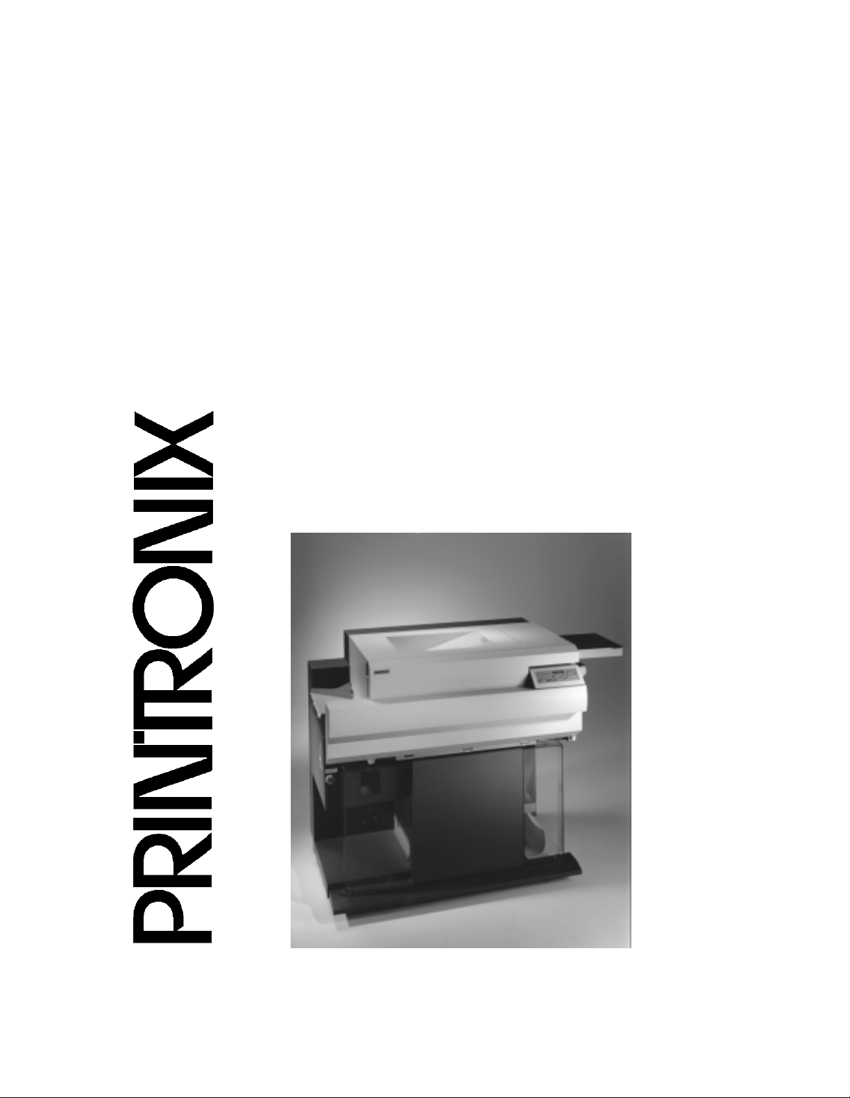
User’s Manual
The Printronix L5035 Multifunction Printer
Page 2
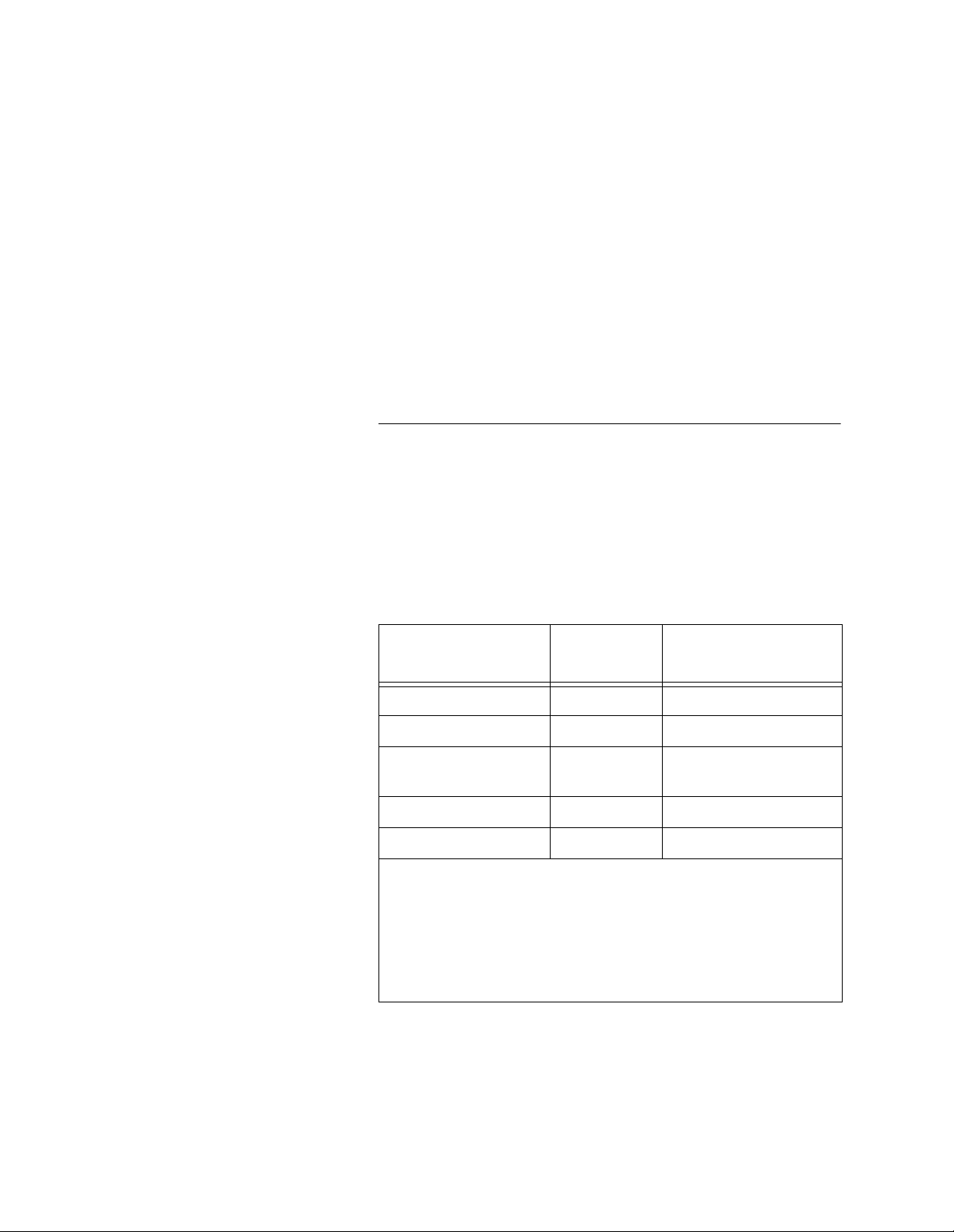
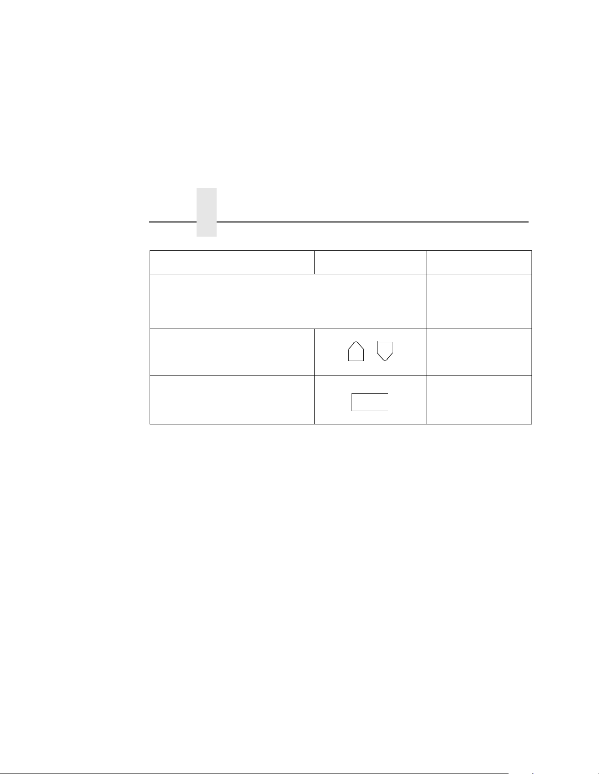
Consumables Information
Printronix® has years of experience designing printer imaging
systems. For the best possible performance of your Printronix
printer, use Genuine Printronix parts and supplies.
For the name of your nearest Printronix full service distributor, call:
United States (800) 733-1900 or (714) 368-2300
Europe (33) 1-46-25-1900
Singapore (65) 548-4116
Consumable Item Part Number
Toner cartridge 703532-001 21,000
Waste toner bottle 202984-001 150,000
Photoreceptor drum 703535-001 150 - 300,000
Developer 703548-001 150,000
Developing Unit 705739-001 600,000
Note 1: Varies with paper size, media type, and toner coverage.
Note 2: Inspect every 150,000 pages; clean if needed. Replace
at 300,000 pages or sooner of print quality is no longer
acceptable. Drum life is dependent upon media used and proper
maintenance and operation of the printer. Print media other than
bond paper (e.g., labels, card stock, plastic, or vinyl) may reduce
drum life as much as 50%.
For more information, please go to our website at
www.printronix.com.
Replacement Interval
(in Pages)
See Note 2
1
Page 3

L5035 Multifu nctio n Prin ter
User’s Manual
706590-001D
Page 4

Software License Ag re emen t
CAREFULLY READ THE FOLLOWING TERMS AND
CONDITIONS BEFORE USING THIS PRINTER. USING THIS
PRINTER INDICATES YOUR ACCEPTANCE OF THESE TERMS
AND CONDITIONS. IF YOU DO NOT AGREE TO THESE TERMS
AND CONDITIONS, PROMPTLY RETURN THE PRINTER AND
ALL ACCOMPANYING HARDWARE AND WRITTEN MATERIALS
TO THE PLACE YOU OBTAINED THEM, AND YOUR MONEY
WILL BE REFUNDED.
Definitions.
“Software” shall mean the digitally encoded, machine-readable
data and program. The term “Software Product” includes the
Software resident in the printer and its documentation. The
Software Product is licensed (not sold) to you, and Printronix, Inc.
either owns or licenses from other vendors who own, all copyright,
trade secret, patent and other proprietary rights in the Software
Product.
License.
1. Authorized Use. You agree to accept a non-exclusive license
to use the Software resident in the printer solely for your own
customary business or personal purposes.
2. Restrictions. a. To protect the proprietary rights of Printronix, Inc., you
agree to maintain the Software Product and other
proprietary information concerning the typefaces in strict
confidence.
b. You agree not to duplicate or copy the Software Product.
c. You shall not sublicense, sell, lease, or otherwise transfer
all or any portion of the Software Product separate from the
printer, without the prior written consent of Printronix, Inc.
d. You may not modify or prepare derivative works of the
Software Product.
Page 5

e. You may not transmit the Software Product over a network,
by telephone, or electronically using any means; or reverse
engineer, decompile or disassemble the Software.
f. You agree to keep confidential and use your best efforts to
prevent and protect the contents of the Software Product
from unauthorized disclosure or use.
3. Transfer. You may transfer the Software Product with the
printer, but only if the recipient agrees to accept the terms and
conditions of this Agreement. Your license is automatically
terminated if you transfer the Software Product and printer.
Limited Software Product Warranty
Printronix, Inc. warrants that for ninety (90) days after delivery, the
Software will perform in accordance with specifications published
by Printronix, Inc. Printronix, Inc. does not warrant that the Software
is free from all bugs, errors and omissions.
Remedy
Your exclusive remedy and the sole liability of Printronix, Inc. in
connection with the Software is replacement of defective software
with a copy of the same version and revision level.
Disclaimer of Warranties and Limitation of Remedies
1. THE PARTIES AGREE THAT ALL OTHER WARRANTIES,
EXPRESS OR IMPLIED, INCLUDING WARRANTIES OF
FITNESS FOR A PARTICULAR PURPOSE AND
MERCHANTABILITY ARE EXCLUDED.
Printronix, Inc. does not warrant that the functions contained in
the Software will meet your requirements or that the operation
of the Software will be uninterrupted or error free.
Printronix, Inc. reserves the right to make changes and/or
improvements in the Software without notice at any time.
2. IN NO EVENT WILL PRINTRONIX, INC. BE LIABLE FOR
LOST PROFITS, LOST DATA, BUSINESS INTERRUPTIONS,
OR ANY OTHER DIRECT, INDIRECT, INCIDENTAL OR
CONSEQUENTIAL DAMAGES ARISING OUT OF THE USE
OF OR INABILITY TO USE THIS PRODUCT, EVEN IF
PRINTRONIX, INC. HAS BEEN ADVISED OF THE
Page 6

POSSIBILITY OF SUCH DAMAGES, OR ANY DAMAGES
CAUSED BY THE ABUSE OR MANIPULATION OF THE
SOFTWARE. SOME STATES DO NOT ALLOW THE
EXCLUSION OR LIMITATION OF LIABILITY FOR
CONSEQUENTIAL OR INCIDENTAL DAMAGES, SO THE
ABOVE LIMITATION MAY NOT APPLY TO YOU.
3. Printronix, Inc. will not be liable for any loss or damage caused
by delay in furnishing a Software Product or any other
performance under this Agreemen t.
4. Our entire liability and your exclusive remedies for our liability
of any kind (including liability for negligence except liability for
personal injury caused solely by our negligence) for the
Software Product covered by this Agreement and all other
performance or nonperformance by us under or related to this
Agreement are limited to the remedies specified by this
Agreement.
5. California law governs this Agreement.
Termination of License Agreement
This License shall continue until terminated. This license may be
terminated by agreement between you and Printronix, Inc. or by
Printronix, Inc. if you fail to comply with the terms of this License
and such failure is not corrected within thirty (30) days after notice.
When this License is terminated, you shall return to the place you
obtained them, the printer and all copies of the Software and
documentation.
U.S. Government Restricted Rights
Use, duplication or disclosure by the Government is subject to
restrictions as set forth in the Rights in Technical Data and
Computer Software clause at FAR 242.227-7013, subdivision (b)
(3) (ii) or subparagraph (c) (1) (ii), as appropriate. Further use,
duplication or disclosure is subject to restrictions applicable to
restricted rights software as set forth in FAR 52.227-19 (c) (2).
Acknowledgement of Terms and Conditions
YOU ACKNOWLEDGE THAT YOU HAVE READ THIS
AGREEMENT, UNDERSTAND IT, AND AGREE TO BE BOUND
Page 7

BY ITS TERMS AN D CON DI TI ONS. N EIT HER PA RT Y SHAL L BE
BOUND BY ANY STATEMENT OR REPRESENTATION NOT
CONTAINED IN THIS AGREEMENT. NO CHANGE IN THIS
AGREEMENT IS EFFECTIVE UNLESS WRITTEN AND SIGNED
BY PROPERLY AUTHORIZED REPRESENTATIVES OF EACH
PARTY. BY USING THIS PRINTER, YOU AGREE TO ACCEPT
THE TERMS AND CONDITIONS OF THIS AGREEMENT.
Communication Notices
Federal Communications Commission (FCC) Statement: This
equipment has been tested and found to comply with the limits for a
Class A digital device, pursuant to Part 15 of the FCC Rules. These
limits are designed to provided reasonable protection against
harmful interference when the equipment is operated in a
commercial environment. This equipment generates, uses, and can
radiate radio frequency energy and, if not installed and used in
accordance with the instruction manual, may cause harmful
interference to radio communications. Operation of this equipment
in a residential area is likely to cause harmful interference, in which
case the user will be required to correct the interference at his own
expense.
Properly shielded and grounded cables and connectors must be
used in order to meet FCC emission limits. Printronix is not
responsible for any radio or television interference caused by using
other than recommended cables and connectors or by any
unauthorized changes or modifications to this equipment.
Unauthorized changes or modifications could void the user’s
authority to operate the equipment.
This device complies with Part 15 of the FCC Rules. Operation is
subject to the following two conditions: (1) this device may not
cause harmful interference, and (2) this device must accept any
interference received, including interference that may cause
undesired operation.
Canadian Department of Communications Compliance
Statement: This Class A digital apparatus complies with Canadian
ICES-003.
Page 8

Avis de conformite aux normes du ministere des
Communcations du Canada: Cet appareil numerique de la classe
A est conform á norme NMB-003 du Canada.
European Community (EC) Conformity Statement:
This product is in conformity with the protection requirements of EC
Council Directive 89/336/EEC on the approximation of the laws of
the Member States relating to electromagnetic compatibility.
Printronix cannot accept responsibility for any failure to satisfy the
protection requirements resulting from a non-recommended
modification of the product, including the fitting of non-Printronix
option cards.
German Conformity Statement:
Zulassungsbescheinigung Gesetz über die elektromagnetische
Verträglichkeit von Geraten (EMVG) vom 30. August 1995
Dieses Gerät ist berechtigt in Übereinstimmung mit dem deutschen
das EG-Konformitätszelchen - CE - zu führen.
Der Außteller der Konformitätserklärung ist die Printronix......(1)
Informationen in Hinsicht EMVG Paragraph 3 Abs. (2) 2:
Das Gerät erfüllt die Schutzanforderungen nach EN 50082-1 und
EN 55022 Klasse A.
EN 55022 Klasse A Geräte bedürfen folgender Hinweise:
Nach dem EMVG: “Geräte dürfen an Orten, für die sie nicht
asreichend entstört sind, nur mit besonderer Genehmigung des
Bundesminester s für Po st und Teleko mmu nik at ion oder des
Bundesamtes für Post und Telekommunikation betrieben werden.
Die Genehmigung wird erteilt, wenn keine elektromagnetischen
Störungen zu erwarten sind.” (Auszug aus dem EMVG, Paragraph
3, Abs. 4) Dieses Genehmigungsverfahren ist nach Paragraph 9
EMVG in Verbindung mit der entsprechenden Kostenverordnung
(Amtsblatt 14/93) kostenpflichtig.
Nach der EN 55022: “Dies ist eine Einrichtung der Klasse A. Diese
Einrichtung kann im Wohnbereich Funkstörungen verursachen; in
diesem Fall kann vom Betreiber verlangt werden, angemessene
Maßnahmen durchzuführen und dafür aufzkommen.”
Page 9
Anmerkung: Um die Einhaltung des EMVG sicherzustellen sind die
Geräte, wie in den Handbüchern angegeben, zu installieren und zu
betreiben.
This product has been tested and found to comply with the limits for
Class A Information Technology Equipment according to European
Standard EN 55022. The limits for Class A equipment were derived
for commercial and industrial environments to provide reasonable
protection against interference with licensed communication
equipment.
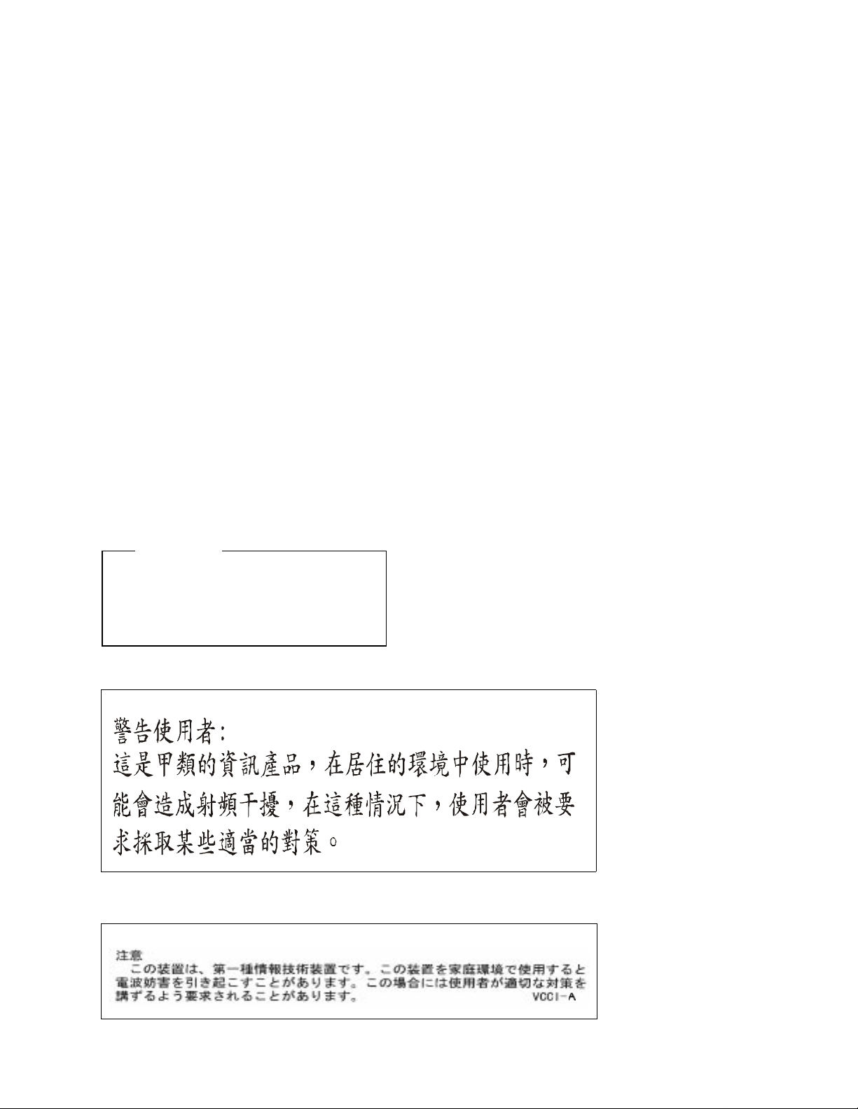
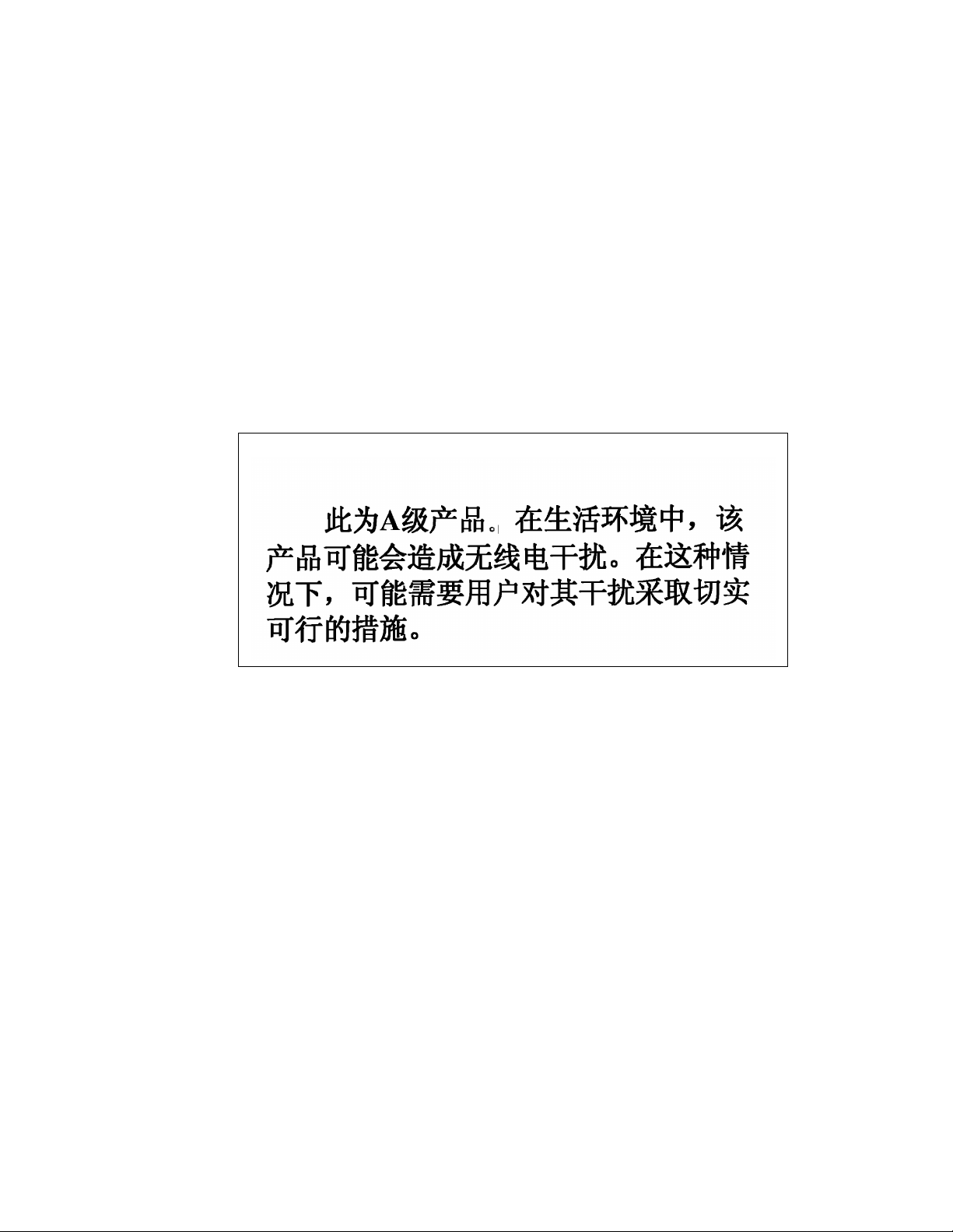
Warning
This is a Class A product. In a domestic
environment this product may cause radio
interference in which case the user may be
required to take adequate measures
.
Page 10
T rademark Ackno wledgeme nts
IBM, OS/2, and Proprinter are registered trademarks, and IPDS
and PC-DOS are trademarks of International Business Machines
Corporation.
Centronics is a registered trademark of Genicom Corporation.
CSA is a registered certification mark of the Canadian Standards
Association.
Dataproducts is a registered trademark of Dataproducts
Corporation.
Epson is a registered trademark of Seiko Epson Corporation.
EIA is a registered service mark of the of the Electronic Industries
Association.
Ethernet is a trademark of Xerox Corporation.
DuraFusion, IGP, LaserLine, LinePrinter Plus, PGL, PSA and
Printronix are registered trademarks of Printronix, Inc.
Hitachi is a registered trademark of Kabushiki Kaisha Hitachi
Seisakusho DBA Hitachi, Ltd.
MS-DOS and Windows are registered trademarks of Microsoft
Corporation.
Page 11

PhoenixPage PCL 5 is a registered trademark of Phoenix
Technologies LTD.
PKUNZIP is a registered trademark of PKWARE, Inc.
3M is a registered trademark of Minnesota Mining and
Manufacturing Company.
SELFOC is a registered trademark of Nippon Sheet Glass Co., Ltd.
Toray is a registered trademark, and Toraysee is a trademark of
Toray Industries, Inc.
UL is a registered certification mark of Underwriters Laboratories,
Inc.
This product uses Intellifont Scalable typefaces and Intellifont
technology. Intellifont is a registered trademark of Agfa Division,
Miles Incorporated (Agfa).
CG, Garth Graphic, Intellifont, and Type Director are registered
trademarks, and Shannon and CG Triumvirate are trademarks of
Agfa Division, Miles Incorporated (Agfa). CG Bodoni, CG Century
Schoolbook, CG Goudy Old Style, CG Melliza, Microstyle, CG
Omega, and CG Palacio are products of Agfa Corporation. CG
Times, based on Times New Roman under license from The
Monotype Corporation Plc is a product of Agfa.
Univers is a registered trademark of Linotype AG and/or its
subsidiaries.
Letraset is a registered trademark, and Aachen, Revue and
University Roman are trademarks of Esselte Pendaflex
Corporation.
Futura is a registered trademark of Fundición Tipográfica Neufville,
S.A.
ITC Avant Garde Gothic, ITC Benguiat, ITC Bookman, ITC
Century, ITC Cheltenham, ITC Clearface, ITC Galliard, ITC
Korinna, ITC Lubalin Graph, ITC Souvenir, ITC Tiepolo, ITC Zapf
Chancery, and ITC Zapf Dingbats are registered trademarks of
International Typeface Corporation.
Albertus, Gill Sans, and Times New Roman are registered
trademarks, and Monotype Baskerville is a trademark of The
Page 12

Monotype Corporation Plc, registered in the U.S. Pat. and TM office
and elsewhere.
Hiroshige and Marigold are trademarks of AlphaOmega
Typography, Inc.
Printronix, Inc. makes no representations or warranties of any kind
regarding this material, including, but not limited to, implied
warranties of merchantability and fitness for a particular purpose.
Printronix, Inc. shall not be held responsible for errors contained
herein or any omissions from this material or for any damages,
whether direct, indirect, incidental or consequential, in connection
with the furnishing, distribution, performance or use of this material.
The information in this manual is subject to change without notice.
This document contains proprietary information protected by
copyright. No part of this document may be reproduced, copied,
translated or incorporated in any other material in any form or by
any means, whether manual, graphic, electronic, mechanical or
otherwise, without the prior written consent of Printronix, Inc.
Copyright 2000, Printronix, Inc. All rights reserved.
Page 13

Table of Contents
1 Introduction............................................. 19
About This Manual...............................................................19
General Safety Precautions.................................................20
Safety Label Locations And Printer Views...........................22
About The Printer ................................................................27
Features........................................................................27
Emulations ....................................................................27
Fonts And Forms...........................................................28
2 Initial Setup............................................. 29
Installation Overview ...........................................................29
Loading Paper .....................................................................30
Loading Cut Sheet Paper (Option)................................33
Powering On The Printer.....................................................40
Power Paper Stacker (Option)......................................41
Parts Of The Power Stacker................................................42
Stacker Operation Keys ................................................43
Setting The Stacker Page Length........................................44
Setting The Printer Page Length .........................................44
Removing Paper ... ....... ...... ....... ...... ...... ....... .................44
Stacker Full...................................................................45
Using The Control Panel ....................................................46
Liquid Crystal Display (LCD).........................................47
LINE SYNC ...................................................................47
SYS AVAIL....................................................................47
JOB IN PROCESS........................................................47
STAND BY....................................................................47
ONLINE.........................................................................48
FAULT...........................................................................48
13
Page 14

14
Table of Contents
Function Keys ...............................................................48
ONLINE Key .................................................................48
CLEAR Key...................................................................49
TEST Key......................................................................49
SHIFT Key ......................................... ....... ...... ..............49
PAGE EJECT Key ........................................................50
ENTER Key...................................................................50
CANCEL Key ................................................................51
UP And DOWN Keys ....................................................51
NEXT And PREV Keys .................................................51
3 Printer Configuration...............................53
Printer Configuration............................................................53
Unlocking And Locking The Configuration Menu..........54
Unlocking The Configuration Menu...............................54
Locking The Configuration Menu..................................54
Moving Within The Configuration Menu........................55
Printing The Current Configuration ...............................56
Factory Settings............................................................57
Changing Printer Configurations...................................62
Saving Configurations.................. ...... ...........................6 4
Configuration Menus.....................................................67
Paper Control Menu......................................................68
Mode Menu...................................................................76
Config. Control Menu ....................................................77
Host Interface Menu......................................................80
Centronics Parameters .................................................81
Dataproducts Parameters .............................................85
Serial Parameters (RS-232 And RS-422) ....................88
Miscellaneous Menu ...... ....................................... ...... .97
Font Memory Menu ....................................................101
Test Print Menu ..........................................................105
Print Statistics Menu ...................................................106
Maintenance Menu ....................................................107
Page 15

Table of Contents
Virtual Printer Menu ....................................................108
Loading Flash Memory (If Equipped)..........................109
The CNVT2FLS Utility Program ........................................110
Downloading Into Flash Memory .......................................112
Flash Messages..........................................................121
4 Consumables Replacement..................123
Consumable Replacement ................................................123
Replacement Intervals ................................................123
Replacing The Toner Cartridge...................................124
Replacing The Waste Toner Bottle .............................128
Installing The Photoreceptor Drum .............................130
Proper Disposal Of A Drum Unit .................................139
Developing Unit Installation.........................................140
Replacing The Developer............................................143
Developing Unit Removal............................................144
Replacing The Developing Unit...................................147
5 Scheduled Maintenance .......................151
Maintaining Print Quality.............................. ....... ...... ....... ..151
Maintenance Tools ................... ....... ...... ...... ....... ...... ....... .. 152
Service Level Page Counts ...............................................153
Clearing Service Level Messages .....................................154
Maintenance Schedules ........... ....... ...... ............................155
User Cleaning Schedule ........................................... .. 155
User Replacement Schedule .................................... .. 156
Tech Service Replacement Schedule.........................157
General Cleaning...............................................................164
Cleaning......................................................................164
Cleaning The Chargers...............................................172
Cleaning The Fuser Unit Cover Glass ........................178
Cleaning The Cut Sheet Option Rollers......................183
Major Cleaning ..................................................................189
Cleaning......................................................................189
15
Page 16

Table of Contents
Discharge LED............................................................193
Photoreceptor Drum....................................................194
SELFOC Lens
®
(LED Print Head)...............................195
6 Troubleshooting ....................................197
Troubleshooting.................................................................197
Diagnostics .................................................................197
Fanfold Paper Jams ..........................................................198
Paper Jam Near The Tractor ......................................198
Paper Jam Near The Paper Output Section ...............199
Cut Sheet Paper Jams ......................................................203
Paper Jam At The Back Of The Paper Cassette ........203
Paper Jam In The Transport Input Section.................206
Paper Jam In The Transport Output Section ..............210
Paper Jam In The Face Up Or Down Paper Path .............211
System Status And Error Messages..................................212
Messages....................................................................212
Error Messages...........................................................217
16
A Maintenance Log Sheets......................225
Level A Maintenance - 15,000 Pages (User) ..............226
Level B Maintenance -150,000 (User) ........................227
Level C Maintenance - 600,000 (User).......................228
Level D Maintenance - 300,000 (Service Kit) .............229
Level E Maintenance - 600,000 (Service Kit)..............230
Level F Maintenance - 900,000 (Service Kit)..............231
Level G Maintenance - 1,200,000 (Service Kit) ..........232
Level H Maintenance - 2,400,000 (Service Kit)...........233
B Specifications .......................................235
Paper Specifications ...................................................235
Performance Characteristics.......................................238
Host Interfaces............................................................241
Emulations .................................................................241
Page 17

Table of Contents
Memory Requirements................................................241
Safety Regulations .....................................................242
Electromagnetic Interference .....................................242
Physical Characteristics And Environment ................242
C Host I/O Interfaces ............................... 245
Overview............................................................................245
Performance Considerations.......................................247
RS-232 Serial Interface...............................................249
RS-422 Serial Interface...............................................253
Centronics Parallel Interface.......................................257
Dataproducts Parallel Interface...................................261
Termination Resistors .................................................265
17
Page 18

Table of Contents
18
Page 19

1 Introduction
About This Manual
This manual explains how to use your printer.
Safety Notices And Special Information
For your safety and to protect valuable equipment, it is very
important that you read and comply with all information highlighted
under the following special headings:
WARNING
CAUTION
A warning notice calls attention to a condition that could harm
you.
WARNUNG
Ein Warhinweis dieser Art weist auf Verletzungsgefahr hin.
AVISO
Las notas de adviso llaman la atención sobre una condición
que puede causar lesiones.
ATTENTION
Attire votre attention sur une opération pouvant présenter un
danger.
AVVERTENZA
Un’indicazione di avvertenza segnala una condizione di
pericolo suscttibile causare lesioni all’operatore.
A caution notice calls attention to a condition that could
damage the printer.
19
Page 20

Chapter 1 General Safety Precautions
IMPORTANT
An important notice provides information that is vital to proper
operation of the printer.
NOTE: A note provides information and helpful tips about printer
operation.
Control Panel Keys And Display Messages
Keys and indicators that are labeled on the printer are printed in
uppercase letters. For example:
Press ENTER to select the value shown on the LCD.
Messages that appear on the control panel message display (called
the Liquid Crystal Display, or LCD), are printed in uppercase letters
and enclosed in quotation marks. For example:
“ENTER SWITCH LOCKED" appears on the LCD.
General Safety Pr ecautio ns
Observe the following precautions at all times to ensure safe
operation of the printer.
Read all instructions and save them for future use.
20
Follow all safety notices and instructions printed in this manual and
marked on the printer.
The operator-accessible power switch does not shut off all power to
the printer. You must unplug the power cord to shut off all power to
the printer.
The power outlet must be near the equipment and easily
accessible.
The printer relies on protective devices in the building installation
for protection. The printer must be connected to a 30 Amp, 250 V
outlet.
Do not operate the printer in a room that is not properly ventilated.
The room should be at least 1,000 cubic feet with a complete air
exchange every two hours.
Page 21

Remove packaging materials carefully and save them. If the printer
is powered on without removing all internal tape and packing, the
printer may be damaged.
Keep combustible materials away from the printer. Dispose of used
toner properly, as it is flammable.
Some components in the printer are potentially hazardous. For
example, the fuser unit becomes very hot under normal operating
conditions, and several components use high voltage.
Handle the photoreceptor drum properl y, due to the nature of the
material. Do not put used drums in the trash; ship them to the
appropriate disposal facility for recycling. (See page 139.)
Do not block or obstruct any cabinet ventilation slots.
Never spill liquid on or in the printer. Use only approved cleaning
agents and methods.
Put nothing on the power cord. Do not locate the power cord where
people will walk on it. Do not place the power cord under any
carpet.
Do not lean on or put heavy objects on top of the printer.
Do not put your hand into the power paper stacker when the printer
is in operation.
Turn off the power immediately if the printer emits an unusual noise
or smell.
Do not look directly at the flash lamp light.
21
Page 22
Chapter 1 Safety Label Locations And Printer Views
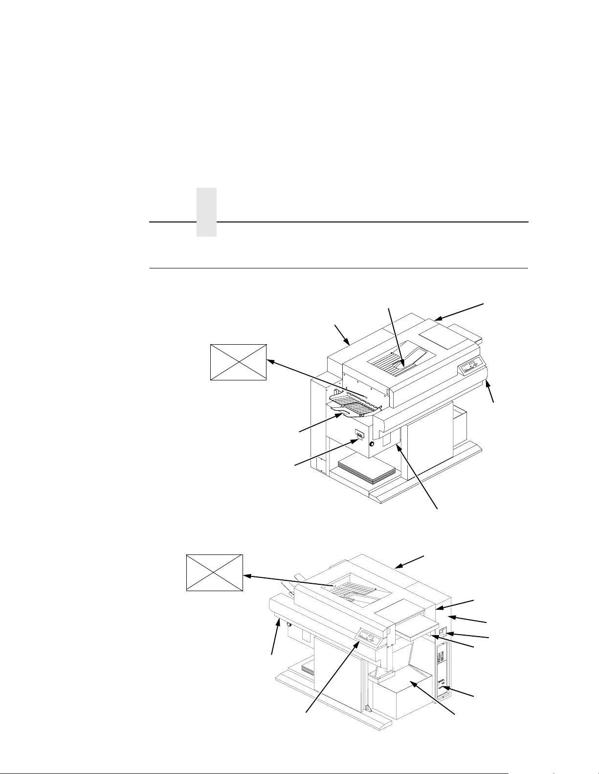
Safety Label Location s And Printer V iews
E
14
15
13
1
4
13
2
3
22
E
12
11
5
6
7
8
9
10
Page 23

Legend:
1) Face Down Paper Output Tray
2) Top Cover
3) Front Upper Cover
4) Power Paper Stacker(Optional)
5) Top Cover
6) Cut Sheet Paper Input Cassette (Optional)
7) Power Switch
8) CAUTION
9) Host I/O Connections
10) Fanfold Paper
11) Control Panel
12) Front Upper Cover
13) Rear Cover
14) CAUTION
15) Face Up Paper Output Tray
Figure 1: Front and Side Views
23
Page 24
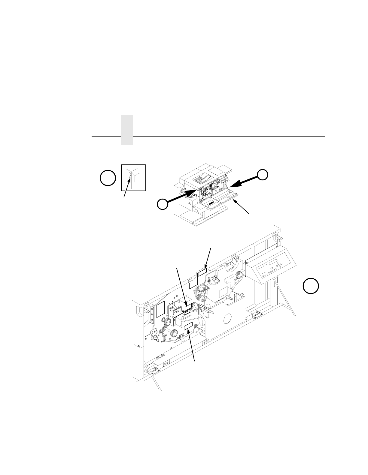
Chapter 1 Safety Label Locations And Printer Views
%
$
5
%
1
2
4
$
24
3
Legend:
1) Front Upper Cover
2) CAUTION
3) CAUTION
4) WARNING
5) Open/Close Button
Figure 2: Front View with Front Upper Cover Open
Page 25
2
1
3
4
5
6
7
8
9
10
11
12
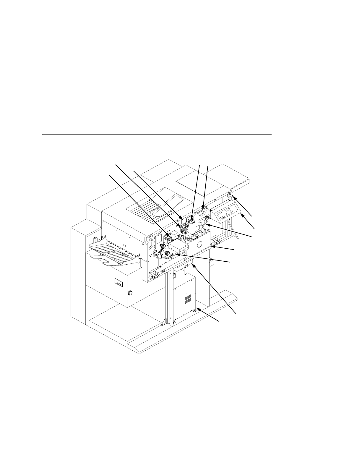
Legend:
1) Fuser Unit
2) Cleaning Unit
3) Discharge LED (not visible)
4) Main Charger
5) Toner Cartridge
6) Optional Cut Sheet Feeder Unit
7) Control Panel
8) Developing Unit
9) Waste Toner Recovery Unit
10) Transport Unit
11) Smoke Filter Box
12) Power Supply for Flash Lamp
Figure 3: Front View with Front Covers Removed
25
Page 26

Chapter 1 Safety Label Locations And Printer Views
2
1
$
Legend:
1) Power Switch
2) CAUTION
3) Parallel Port
4) 232/422 Switch
5) Diagnostic Port
6) Serial Port
7) Optional Coax/ Twinax Port
$
3
4
7
5
6
26
Figure 4: Rear Cover
Page 27

About The Printer
Features
Printing speed is 35 pages per minute on continuous letter size and
A4 size fanfold forms (long edge fed). In the optional cut sheet
mode, printing speed is 27 pages per minute on letter size and A4
size cut sheet forms (long edge fed). The printer produces printed
output with a 300 x 300 or, optionally, 240 x 240 or 400 x 400 dotsper-inch (dpi) resolution in either the continuous form or cut sheet
printing mode. See Appendix B for printer specifications.
Features include the following:
• Continuous fanfold paper and optional cut sheet forms
handling.
• User-replaceable toner cartridge.
• DuraFusion
• Liquid crystal display that provides operating and error
messages.
®
flash fusion technology.
Features
• Flash memory which stores preset configurations and
emulations.
• Serial and parallel interfaces.
• Coax/Twinax interface (optional).
• Power stacker (optional).
Emulations
Depending on how your printer was ordered, it will come equipped
with one of two emulations: either the PhoenixPage PCL 5
emulation software or the Printronix® LinePrinter Plus® emulation
software (which emulates an impact printer). Printronix LinePrinter
Plus includes the following printer protocols:
• P-Series
• P-Series XQ
®
27
Page 28

Chapter 1 About The Printer
• Serial Matrix
®
/PGL
®
®
III XL
FX-1050
®
• Proprinter
• Epson
Printronix LinePrinter Plus provides portrait and landscape image
orientation. Automatic 1-up, 2-up, 4-up, and gray bar overprinting
are also provided. The emulation offers optional proportional
(scalable) fonts and multi-up form definition capability as well.
The following optional emulations are also available:
• IGP
• IGP/VGL
• IPDS™
For specific information on each emulation, see the appropriate
emulation manual.
Fonts And Forms
28
The printer provides a variety of resident fonts. The emulation you
are using determines what resident fonts are available. For
example, the LinePrinter Plus emulation provides CG Times, Letter
Gothic, Courier, OCR-A, and OCR-B as standard sets of fonts.
With either the LinePrinter Plus or PCL 5 emulations, you can load
additional fonts into printer memory from the host computer. When
additional fonts are in printer memory, you can then access them in
the same way as the resident fonts. Note that if you download fonts
from the host computer and do not save them, the downloaded
fonts will be lost when the printer is powered off.
You can store forms together with fonts. The storage space for
forms and fonts depends upon the amount of printer memory and/
or non-volatile Flash memory space available. You can manipulate
different fonts and/or forms depending upon the emulation installed.
Page 29

2 Initial Setup
Installation Overview
This chapter explains how to load paper, power on the printer, use
the optional power stacker, and how to use the control panel.
The installation and setup of your printer should be performed by a
service pr ovider trained and authorized by Printronix. Your service
provider is also responsible for doing a preinstallation site survey,
unpacking the printer, connecting the power and host data cables,
and installing the first set of consumable items in the printer.
Depending on the terms of your service contract, your service
provider might also power on your printer and configure it.
As the owner of the printer, it is your responsibility to prepare the
printer site. This includes providing adequate ventilation and power
for the printer.
29
Page 30

Chapter 2 Loading Paper
Loading Paper
The following section explains how to load fanfold paper. To load
cut sheet paper, go to page 33.
Loading Fanfold Paper
When loading fanfold paper, be sure the leading edge of the
paper has a clean, separated perforation (without ragged
edges or paper chaff).
NOTE: You do not need to power off the printer power to replace
paper. If you leave the printer on and replace the paper it
will resume printing where it left off when you put it on line.
To load fanfold paper, do the following steps. Repeat this
procedure whenever top-of-form must be reset (e.g., after clearing
a paper jam, loading new paper, etc.). For details on clearing paper
jams, refer to Chapter 6, “Troubleshooting.”
1.
If your printer has the optional power paper stacker installed,
set the stacker page length adjustment on the side of the power
stacker to match the paper length to be used.
30
2.
Place the fanfold paper box under the tractor unit with the first paper fold toward the printer.
Page 31

IMPORTANT
The first fold of the paper should be facing toward the printer.
Otherwise, a paper jam could occur during printing (see
below).
1
IMPORTANT
2
3
Legend:
1) Tractor Unit
2) Lower Paper Guides
3) First paper fold is toward printer
3. Pass the leading edge of the paper between the lower paper
guides, as shown in the illustration above.
To prevent jams, the first fold of the paper faces toward the
printer as shown.
31
Page 32

Chapter 2 Loading Paper
IMPORTANT
3
Legend:
1) Tractor Pins
2) Tractor Lock
3) Tractor Gate
1
2
4. Unlock only the right tractor by pushing forward on the tractor lock.
5. Open the left and right tractor gates and place the paper about half-way onto the tractor pins.
Do not push the paper past the tractors into the area of the
paper jam sensor.
32
6. Close the left tractor gate.
7. Move the right tractor to the left or right until its pins line up with
the holes in the right edge of the paper, put the paper in the
pins, then close the right tractor gate.
NOTE: After you place the paper on the tractors, introduce a slight
amount of side-to-side tension into the paper. Set the right
tractor far enough to the right so that there are no wrinkles,
looseness, etc. in the paper. Be careful not to set the right
tractor too far to the right, however, as too much tension
may cause the paper holes to tear away from the tractor
pins.
Page 33

Loading Cut Sheet Paper (Option)
8. Tension the paper by moving the right tractor slightly outward
and lock the right tractor with the tractor lock.
9. If you are reloading paper following a “FAN-FOLD PAPER
EMPTY” message with the printer power on, press ONLINE to
place the printer online. The printer automatically sets the
physical top of form at the leading edge of the paper and
resumes printing.
Loading Cut Sheet Paper (Option)
If your printer is equipped with the cut sheet paper feed option,
upper and lower paper input cassettes are also provided. When
printing on cut sheet paper, you can select either of two paper
output trays: the face down tray (default) or the face up tray.
To change the paper output tray selection, see the Cut Sheet
Output option on the Paper Control menu, page 69.
NOTE: If the printer runs out of paper during printing, you do not
need to turn off printer power to replace paper. If you leave
the power on when you replace the paper and place the
printer online, it will resume printing automatically where it
left off.
To load cut sheet paper, do the following steps:
1.
Pull out the paper cassette and remove its cover.
33
Page 34

Chapter 2 Loading Paper
2. Load the new paper uniformly in the cassette, making sure the
leading edge of the paper is at the front of the cassette. Do not
load more paper than specified below, otherwise a paper jam
may occur.
17- 20 lb.
bond
21 - 44 lb.
bond
Upper cassette 250 sheets or less
Lower cassette 500 sheets or less
Upper cassette 1 inch or less in thickness
Lower cassette 2 inches or less in thickness
1
1
2
2
Legend:
1) Cassette Cover
2) Cassette
3. Cover the cassette and insert it into the printer, making sure it
is completely seated. If the cassette is not fully seated, a paper
jam may result.
34
4. If you are reloading paper following a “CUT-SHEET PAPER
EMPTY” message with the printer power on, press ONLINE to
place the printer online. The printer resumes printing.
NOTE: Occasionally, paper may become moist and wavy, resulting
in poor print quality. If this occurs, remove the wavy sheets
of paper from the cassette and replace them with those
from a new package.
Page 35

Loading Cut Sheet Paper (Option)
In order to minimize the possibility of a paper jam:
• Only use xerographic quality paper.
• Load paper in a cassette which has been adjusted for the exact
paper size. (To set the cassette for the paper size, see the
following section.)
• Do not gather loose paper for use.
• Do not use wrinkled, folded, or moist paper.
• Do not leave paper in the cassettes overnight.
• Always store unused paper in a clean, dry area protected from
sunlight.
• If a paper package is opened but not fully used, rewrap and
seal the package and store it properly for future use.
Changing Cassette Paper Size (Optional Procedure)
The cut sheet option comes with four cassettes (paper trays)
preconfigured for either U.S. or Metric paper sizes. An optional
custom (special) tray for variable cut sheet lengths is also available.
If the configurations of these cassettes do not meet your needs,
you can reconfigure the cassettes as described below, or you can
purchase additional cassettes.
35
Page 36

Chapter 2 Loading Paper
2
1
2
1
3
3
H
T
G
WI
D
T
H
Legend:
1) IPS (Paper Size Insert) 12/22
2) IPS 11/21
3) IPS 10/20
N
E
L
There are three holes in the forward end of the cut sheet paper feed
cassettes. Plastic inserts are set in these holes according to the
size of the cut sheet paper loaded in the cassette (as shown in the
table that follows).
36
When the plastic inserts in the cassette contact the paper size
sensors on the printer, the printer determines that the paper
cassette is in position and identifies the paper size.
Page 37

Loading Cut Sheet Paper (Option)
The following table lists the available standard settings for the cut
sheet paper feed cassette (0 = plastic insert; — = no insert):
Paper Size IPS 12/22 IPS 11/21 IPS 10/20
Legal — 0 0
Ledger 0 0 —
A3 0 — 0
B4 0 — —
Letter — 0 —
A4 — — 0
Custom Size
(variable width 7.0 in
- 12.0 in, variable
length 8. 3 i n - 19.6 in)
000
Cut Sheet Tray Linking
If your printer is equipped with the cut sheet paper feed option, you
can use Tray Linking. Tray Linking is disabled by default. With Tray
Linking enabled, when the active cut sheet paper tray runs out of
paper, the printer will automatically switch to the other paper tray
and continue printing.
To enable or disable this feature, see the Tray Linking option on the
Paper Control menu, page 69.
NOTE: Disable Tray Linking if the two cut sheet paper trays are of
different sizes
If the cut sheet trays are of different sizes, and Tray Linking
is enabled, the printer will not switch to the alternate tray
when the first tray runs out of paper, nor will it display the
usual “CUT-SHEET PAPER EMPTY” message on the
LCD. Instead, the printer stops printing and displays the
message “TRAY MISMATCH.”
37
Page 38

Chapter 2 Loading Paper
To clear this message, either add paper to the active tray,
or insert a matching tray in the alternate tray position. Then
press CLEAR on the control panel.
Tray linking is disabled by the printer automatically when
the lower tray is configured as a variable length tray, and is
selected as a source tray. Tray linking is resumed after the
lower tray is reconfigured to a standard cut sheet paper
size.
Variable Tray Width
If your printer is equipped with the cut sheet paper feed option, you
can override the standard cut sheet paper tray widths with a feature
called Custom Tray Width. The standard cut sheet paper tray sizes
are listed in the table on page 37. Using Custom Tray Width and
specially-modified paper trays, it is possible to use nonstandard
paper stock that is wider or narrower than the standard paper
widths.
If you are using the Custom Tray Width feature, use the control
panel to adjust the width of the image in the printer to match your
nonstandard width paper.
38
To set a custom tray width, see Cut Sheet Options on the Paper
Control menu, on page 69.
NOTE: The Custom Tray Width feature requires specially modified
paper trays.
Variable Width is enabled, but the values are resumed after
the lower tray has been reconfigured to standard paper
size.
Paper selection has to be set to the lower tray with a
custom tray inserted in order to make the variable tray
width available through the control panel.
Page 39

Loading Cut Sheet Paper (Option)
Variable Tray Leng th
If your printer is equipped with the cut sheet paper feed option, it is
possible to override the standard cut sheet paper tray lengths. This
feature is called Custom Tray Length. The standard cut sheet paper
tray sizes are listed in the table on page 37. Using Custom Tray
Length and specially modified paper trays, it is possible to use
nonstandard paper stock that is longer or shorter than the standard
paper length. You can use nonstandard length paper only in the
lower tray.
If you are using the Custom Tray Length feature, use the control
panel to adjust the length of the image in the printer to match your
nonstandard length paper from the front panel.
To set a custom tray length, see Cut Sheet Options on the Paper
Control menu, detailed on page 37.
NOTE: The Custom Tray Length feature requires specially
modified paper trays.
Variable Length feature is enabled when the Variable Tray
Length is enabled, but the values are resumed after the
lower tray has been reconfigured to standard paper size.
Paper selection has to be set to the lower tray with a
custom tray inserted in order to make the variable tray
length available through the control panel.
39
Page 40

Chapter 2 Powering On The Printer
Powering On The Printer
1
40
Legend:
1) Power Switch
1. Plug the printer into a 200, 220, or 240 VAC, 30 Amp, 50-60 Hz
power source as shown on the rear panel label. (The DC power
supply must be set for the proper line voltage. Using an
incorrect power source or improperly setting the DC power
supply will damage the printer.)
2. Turn on the printer by setting the power switch to | (on).
3. Note that when you power on the printer, the following occur: a. The printer reads the emulation and displays the message:
“B0: Printer Boot
Please Wait...”
b. The ONLINE indicator lights continuously and STAND BY
goes out.
Page 41

Power Paper Stacker (Option)
NOTE: The printer can be set to power on in the OFFLINE state
instead of the ONLINE state. To print, ONLINE must be lit;
if it is not, press ONLINE.
In the event other messages and prompts appear on the control
panel, answer the prompts and follow the directions as explained in
“System Status and Error Messages” on page 212.
Power Paper Stacker (Option)
Safety Feature
To prevent injuries, the optional power stacker is equipped with two
safety stop bars located under the edge of the stacker. When the
safety bars are pressed, stacker operation stops immediately.
When the AUTO key is pressed, the stacker resumes operation.
41
Page 42

Chapter 2 Parts Of The Power Stacker
Parts Of The Po wer S tacker
.
2
1
2
3
3
1
10
9
9
8
8
4
4
5
5
6
7
7
6
42
Legend:
1) AUTO Key
2) STOP Key
3) DOWN Key
4) HEAVY Key
5) Hook
6) Head/Tail Length Measuring Gauge (in inches)
7) Elevator
8) Safety Stop Bar (not visible in figure)
9) Top/Bottom Adjust Knob
Page 43

Stacker Operation Keys
St ac ker Opera tion Keys
The power paper stacker contains four keys for operating the
elevator:
• AUTO: Sets the elevator in automatic mode. Pressing this key
causes the elevator table to rise until it reaches its maximum
upper position and enables the stacker.
• STOP: Stops the elevator, and displays the message “Stacker
Not Ready” on the printer control panel. The STOP key may be
used to stop the elevator from lowering after pressing the
DOWN key.
• DOWN: Lowers the elevator to its lowest position, or until the
STOP key is pressed.
• HEAVY: ON equals “Heavy Mode” for thicker paper (LED is lit);
OFF equals “Normal Mode” for thinner paper (LED is not lit).
This key is only active in STOP mode and when there is no
paper in the stacker.
When operating the power stacker in Heavy Mode, the maximum
stack height following a cut or page eject depends on the page
length, as shown in the following table:
Page Length (Inches) Max. Stack Height (Inches)
7.0 7.5
7.5 7.2
8.0 7.0
8.5 6.6
9.0 6.4
9.5 6.1
10.0 5.8
10.5 5.5
11.0 5.3
43
Page 44

Chapter 2 Setting The Stacker Page Length
Page Length (Inches) Max. Stack Height (Inches)
11.5 5.0
12.0 4.8
NOTE: Normal Mode supports up to 28 lb. bond (105 g/m2). Heavy
Mode must be used for media weights greater than 34 lb.
bond (128 g/m
2
) and higher require Heavy Mode for reliable stacking.
m
2
). Some media that are 28 lb. bond (105 g/
Setting The S t ack er Page Len gth
Set the stacker page length to match the actual page length. On the
side of the stacker, locate the adjustment knob and the window
containing a measuring gauge (a pointer with a scale). Rotate the
knob until the pointer matches the page length being used. (See
page 44.)
Setting The Printer Page Length
NOTE: If the printer page length does not match the stacker page
length, the timing of the stacker swinger arm will be
incorrect, resulting in a folding error.
Set the printer page length by following the instructions for
changing printer configurations (see the Paper Control menu on
page 68).
Removing Paper
1. After a print job, press the PAGE EJECT key on the printer control panel.
2. Tear the paper at the perforation.
3. Press the DOWN key on the stacker to lower the elevator.
4. Press the STOP key on the stacker when the elevator is about half-way down.
44
Page 45

Stacker Full
NOTE: The elevator stops automatically when it is fully loaded,
without the STOP key being pressed.
5. Remove the completed print job from the elevator, and do one of the following:
• To change the paper mode, go to Step 6.
• To reload paper after a paper path error, go to Step 7.
• To resume operation, go to Step 8.
6. If necessary, you may change the paper mode at this point, by
pressing the HEAVY key. ON equals “Heavy Mode” for thicker
paper (LED is lit); OFF equals “Normal Mode” for thinner paper
(LED is not lit). This key is only active in STOP mode and when
there is no paper in the stacker.
7.
If the printer reports an error which requires the paper path to
be cleared, be sure to reload the paper with the first perforation
facing inward (see page 30). Then press the CLEAR key on the
control panel. Otherwise, the paper may jam or fold incorrectly.
CAUTION
Always remove all paper from the elevator before pressing the
AUTO key on the stacker. Failure to remove all paper may
damage the stacker.
8.
Press the AUTO key on the stacker to automatically resume operation.
St acker Ful l
1. When the stacker becomes full, the printer automatically
separates the paper at the perforation, returning the edge of
the paper to home position on the tractors.
2. Press the DOWN key on the stacker.
3. Remove all paper from the stacker elevator.
4. Press the AUTO key on the stacker to resume operation.
5. Press the CLEAR key on the printer control panel, to clear the
fault message and place the printer online.
45
Page 46

Chapter 2 Using The Control Panel
6. Check paper input to the printer to insure the first paper
perforation is facing the printer and reload paper, if necessary,
to align the first paper perforation.
7. If the Reprint on Fault option is enabled in the Paper Control
menu, the printer reprints the applicable pages. (See the Paper
Control menu on page 68. Also see “Reprinting Pages after
Fault Condition” on page 212.)
8.
Press the ONLINE key on the printer control panel, to place the printer online.
Using The Control Panel
1
JOB IN
SYS
SYNC
ONLINE FAULT
ONLINE CLEAR TEST SHIFT
AVAIL
PROCESS
STAND BYLINE
CANCEL
PAGE
EJECT
4
Legend:
1) Status Indicators
2) Liquid Crystal Display (LCD)
3) Paper Path Diagram
4) Function Keys
The control panel is located on the top right side of the front cover.
The LCD, status indicators, and function keys are described on the
following pages.
ENTER
PREV
2
UP
DOWN
FUSER DRUM
PAPER PATH
NEXT
3
46
Page 47

Liquid Crystal Display (LCD)
Liquid Crystal Display (LCD)
The liquid crystal display (also called LCD or message display) on
the control panel displays printer operating status, configuration
options, and error codes.
St atus Indicators
The status indicators display the operational status of the printer.
LINE SYNC
Indicating there is activity on the line from the host computer (for
IPDS printers only).
SYS AVAIL
Indicating there is activity to the current address on the line (for
IPDS printers only).
JOB IN PROCESS
When the printer is receiving or processing data, JOB IN
PROCESS flashes. If data has been processed and is waiting to be
printed, or has been printed but not yet fused and ejected by the
printer, JOB IN PROCESS lights continuously.
JOB IN PROCESS does not light when the printer is not processing
data, no data exists in the buffer, and the printer is not receiving
data.
STAND BY
STAND BY flashes while the printer is executing any control panel
command, and while the printer is unavailable for printing due to its
normal system activities, such as while it is booting, printing its
configuration, writing status information, and loading applications.
47
Page 48

Chapter 2 Using The Control Panel
IMPORTANT
Do not press any control panel key when STAND BY is
flashing. It may carry out unwanted commands.
ONLINE
ONLINE lights continuously when the printer is online (when the
printer is ready to print and accept data from the host). It flashes
when the printer is offline or when the printer stops because of an
error.
FAULT
FAULT flashes when the printer is unavailable for printing because
of an internal error.
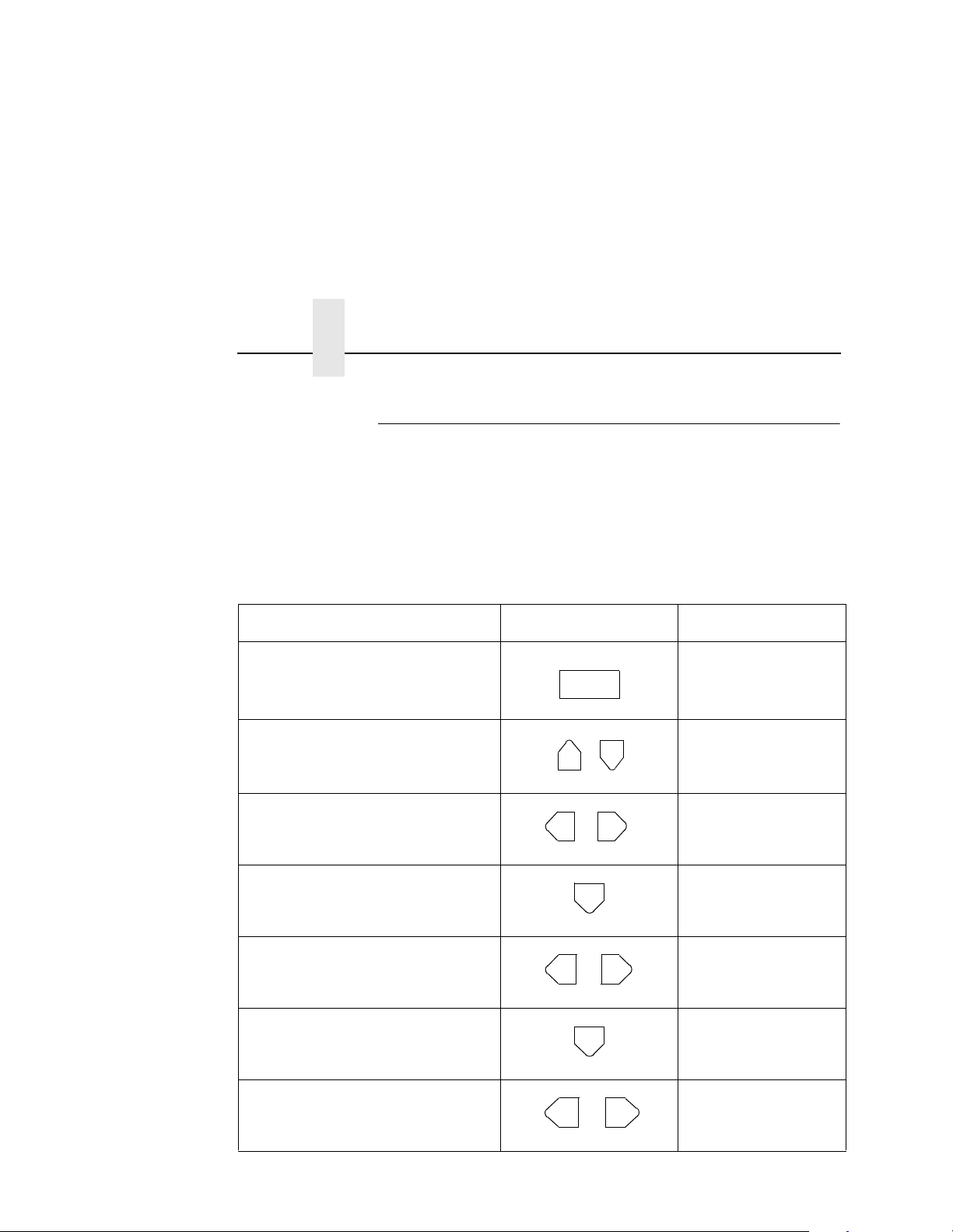
Function Keys
Use the function keys to configure the parameters, or options, of
the printer. You can access these parameters via a structured
menu which is displayed on the LCD. To navigate through the
options, use the UP, DOWN, NEXT, and PREV keys. Press
ENTER to select an option that appears on the LCD.
48
The purpose of each function key (under normal printing mode) is
defined below.
NOTE: The beep you hear when you press a function key verifies
contact.
For specific procedures and information regarding the configuration
menu, refer to Chapter 3, “Printer Configuration.”
ONLINE Key
The ONLINE key toggles the printer online and offline.
• To place the printer online, press ONLINE until the ONLINE
status indicator remains continuously lit. The LCD displays
“ONLINE,” along with the name of the current emulation. The
printer can now receive and process data and print.
Page 49

CLEAR Key
• To place the printer offline, press ONLINE until the ONLINE
status indicator blinks. The LCD displays “OFFLINE.” The
printer stops processing and printing any new data, except for
any pages in process.
• To start downloading files to the printer, press the ONLINE +
PAGE EJECT key. See Chapter 3 for more information.
NOTE: When the printer is not in an error state, pressing ONLINE
in any level of the configuration menu causes the printer to
accept any configuration changes you have entered and
return to online status.
When the printer is in an error state, pressing ONLINE in
any level of the configuration menu causes the printer to
display the fault message again.
CLEAR Key
In the fault state, press the CLEAR key to clear errors and reset the
printer to the offline state (if all errors are cleared).
TEST Key
When the printer is offline, you can run a test print, as configured
under the Test Print menu (page 105), by pressing the TEST key.
To stop the test print, press TEST again.
Pressing TEST when the printer is online will have no effect.
SHIFT Key
This key has no function of its own. It is combined with other keys to
modify their functions.
49
Page 50

Chapter 2 Using The Control Panel
PAGE EJECT Key
The PAGE EJECT key has the following functions when the printer
is online:
When the JOB IN PROCESS status indicator lights steadily,
pressing PAGE EJECT causes the printer to print all data in the
printer. If continuous form paper is used, the page then will be cut
at the perforation (unless the Burst On Eject option is disabled).
When the JOB IN PROCESS status indicator flashes, pressing
PAGE EJECT causes the printer to attempt to print any data in the
buffer. The paper motion caused by the page eject operation may
interrupt the printing of data that is not currently in the buffer. Once
the paper motion has occurred, the data that was not yet in the
buffer should print. If continuous form paper is used, the page then
will be cut at the perforation (unless the Burst On Eject option is
disabled).
To start downloading files to the printer, press the PAGE EJECT +
ONLINE key. See Chapter 3 for more information.
IMPORTANT
50
Do not press PAGE EJECT while JOB IN PROCESS is flashing,
or your print job might become misaligned.
When the JOB IN PROCESS status indicator is not lit or flashing,
PAGE EJECT has no effect.
Pressing the SHIFT + PAGE EJECT keys together at the same
time moves the paper one page length without printing or cutting
the paper. This function is intended to be used with fanfold paper
only. It can be used to feed the paper into (customer-supplied)
postprocessing equipment.
ENTER Key
When you are entering parameters in the configuration menu,
press ENTER to select the value shown in the LCD. The printer will
confirm your selection by placing an asterisk (*) next to the value in
the display. However, if the ENTER key is locked, “ENTE R KEY
LOCKED” appears and the value is not accepted.
Page 51

CANCEL Key
CANCEL Key
The CANCEL key has the following functions when the printer is
offline:
• Cancels the current page in process
• Cancels any pages queued to print but not yet printed
• Cancels any input data not yet processed
• Clears the reprint buffers
• Cancels a download if one is in process.
UP And DOWN Keys
The UP and DOWN keys are used for the configuration menu:
• To unlock or lock the ENTER key, press UP + DOWN at the
same time when the printer is offline.
• To enter the configuration menu, press DOWN when the printer
is offline.
• To move between the different levels in the configuration menu,
either press UP or DOWN as needed.
NEXT And PREV Keys
The NEXT and PREV keys are used to move between the
parameter options on the current level of the configuration menu.
Press NEXT or PREV to move forward or backward through
parameter options.
51
Page 52

Chapter 2 Using The Control Panel
52
Page 53

3 Printer Configuration
Printer Configuration
In order to print data, the printer must respond correctly to interface
signals and commands received from the host computer.
Configuration is the process of matching the printer’s operating
characteristics to those of the host computer. The characteristics
that define the printer’s response to signals and commands
received from the host computer are called configuration
parameters and are found in the configuration menus.
Configuration menu diagrams are shown later in this chapter.
Configuration parameters are retrieved from flash memory, or set
from the control panel. This chapter explains how to set and save
parameters with the control panel.
IMPORT ANT
Configuration directly affects printer operation. Do not change
the configuration of your printer until you are thoroughly
familiar with the procedures in this chapter.
53
Page 54

Chapter 3 Printer Configuration
Unlocking And Locking The Configuration Menu
In order to configure the printer with the control panel, you need to
unlock the ENTER key, which is locked by default. The locked state
secures your configuration, preventing alteration.
Unlocking The Configuration Menu
Step Press LCD Message
1. Place the printer offline OFFLINE
2. Unlock the ENTER key (the LCD message appears briefly).
3. From this point, either print or modify your current configuration.
ONLINE
+
PAPER CONTROL
ENTER KEY
UNLOCKED
Locking The Configuration Menu
Step Press LCD Message
1. At any place within the menu, you can lock the ENTER key.
2. Place the printer online. The second line of the LCD varies, depending on the emulation.
+
ONLINE
ENTER KEY
LOCKED
ONLINE
LINEPRINTER+
54
Page 55

Moving Within The Configuration Menu
Moving Within The Configuration Menu
Movement within the configuration menus is controlled by using the
UP, DOWN, PREV, and NEXT keys. The configuration procedure
discusses this in more detail. You should not make any
configuration changes until you have a printout of your current
configuration. (See page 56.)
The following figure shows an example of the steps to follow to
change a menu option. The illustration is divided into two parts: the
left side shows a portion of a configuration menu, and the right side
shows the keys to press to access a particular parameter and
messages that display after you press each key.
The example shown configures the printer for a form length of 12
inches. It also shows how to move through any menu.
Paper Control
Image Width
2.0 inches
2.1 inches
2.2 inches
2.3 inches
2.4 inches
.
.
.
14.7 inches*
* equals factory default value
1.0 inches
1.5 inches
2.0 inches
2.5 inches
3.0 inches
.
.
.
11.0 inches*
.
.
.
24.0 inches
30.0 inches
Form Length
Press:
ONLINE
OR
ENTER
LCD Message:
OFFLINE
PAPER CONTROL
PAPER CONTROL
Image Width
PAPER CONTROL
Form Length
Form Length
Inch Select*
Inch Select
Length In Inches
Length In Inches
11.0*
Form Length
12.0 inches
Form Length
12.0 inches*
55
Page 56

Chapter 3 Printer Configuration
Printing The Current Configuration
You should always print out and store your configurations for future
reference. The printout provides a list of the parameters you set
when you configured the printer. Each parameter is defined later in
the chapter.
To print the current configuration, follow the steps listed below:
Step Press LCD Message
1. Place the printer off line. OFFLINE
ONLINE
PAPER CONTROL
2. Unlock the ENTER key. ENTER KEY
+
UNLOCKED
3. Select Config. Control. CONFIG. CONTROL
Load Config.
4. Scroll through the Config. Control
menu until you reach Print Config.
OR
CONFIG. CONTROL
Print Config.
5. Select Print Config. Print Config.
Current
6. Select the current option. Print Config.
ENTER
Current
7. The STANDBY light flashes, and the printer prints the specified configuration.
8. Lock the ENTER key. ENTER KEY
+
LOCKED
9. Place the printer online. ONLINE
ON LINE
LINEPRINTER+
56
Page 57

Factory Settings
Factory Settings
The configuration defaults set at the factory are listed below. These
values are available for loading at any time, and are maintained in
the printer until a new configuration is loaded.
Table 1. Factory and Configuration Parameters
Menu Item Default Value
Paper Control
Image Width 14.6 inches
Form Length 11.0 inches
Paper Length Auto. Select
Paper Selection Fanfold
Cut Sheet Output Face Down
Fanfold Output Into Stacker
Horizontal Image Shift 0/100 inches
Vertical Image Shift 0/100 inches
Toner 3
Reprint on Fault Enable
Paper Ty pe Standard
Burst on Eject Enable
Cut Sheet Options
Tray Linking Disable
Variable Upper Tray Width Disable
Variable Lower Tray Width Disable
Variable Lower Tray Length Enable
No Back Feed Disable
57
Page 58

Chapter 3 Printer Configuration
Table 1. Factory and Configuration Parameters
Menu Item Default Value
Mode LinePrinter+
Config. Control
Load Configuration 0
Save Configuration 1
Print Configuration Current
Delete Configuration 1
Power-up Configuration 0
Protect Saved Configuration Disable
Host Interface
Centronics
Data Bit 8 Enable
58
Paper Inst Line Disable
Data Polarity Standard
Strobe Polarity Standard
ACK Polarity Standard
Busy Polarity Standard
Slct Polarity Standard
Fault Polarity Standard
Paper Inst Pol Standard
PE Polarity Standard
NFAULT/PE Ctl Act Together
Page 59

Factory Settings
Table 1. Factory and Configuration Parameters
Menu Item Default Value
Dataproducts
Data Bit 8 Enable
Paper Inst Line Disable
Data Polarity Standard
Strobe Polarity Standard
Data Req Pol Standard
Ready Polarity Standard
Online Polarity Standard
Paper Inst Polarity Standard
Serial
Host Protocol None
Baud Rate 9600 baud
Data Bits 8 bits
Stop Bits 1 bit
Parity None
DTR Function On/Offline&Buf
RTS Function On/Offline&Buf
DTR Polarity Normal
RTS Polarity Normal
Buffer Size 8192 bytes
Number Buffers 2 buffers
FIFO Trigger 14 bytes
Diagnostic None
59
Page 60

Chapter 3 Printer Configuration
Table 1. Factory and Configuration Parameters
Menu Item Default Value
Series 1 Poll 0
Series 1 Delay 0+ Msec
Series 1 Idle Disable
Miscellaneous
Panel Key Sound On
Alarm On
Power-up State Online
Hex Dump Mode Disable
PTX_SETUP Option
Setup Parse Disable
Setup SFCC 21h
60
Display Language English
File System
Overwrite Enable
View Files File 1
Delete Files File 1
Optimize and Reboot
Print File List
Font Memory
Max Char Memory 300 KBytes
Max Cache Memory 200 KBytes
Max Cache Size 900 Characters
Max Cached Char 01 KBytes
Page 61

Factory Settings
Table 1. Factory and Configuration Parameters
Menu Item Default Value
Max Fonts Loaded 05 Fonts
Font Weight
Standard Chars. 115
Bold Chars. 259
Extra Bold Chars. 269
Virtual Printer
Virtual Printer LP+
61
Page 62
Chapter 3 Printer Configuration
Changing Printer Configurations
In order to properly configure the printer, it is important that you
have a current configuration printout, as described previously. From
this printout, determine which parameters you need to change for
the printer to operate correctly with the host computer, or your
specific applications.
To change printer settings such as paper length, emulation, and
host I/O interface, do the following steps:
Step Press LCD Message
1. Place the printer offline. OFFLINE
ON LINE
P APER CONTROL
2. Unlock the ENTER key. ENTER SWITCH
3. Scroll through the menu until
you reach the appropriate
+
OR
UNLOCKED
OFFLINE
HOST INTERFACE
menu.
4. Select the menu to access
available parameters or
HOST INTERFACE
Centronics
submenus.
5. Scroll through the submenus or
parameters until you reach the
OR
HOST INTERFACE
Serial
one you want.
6. Select this submenu parameter to access the value options.
7. Scroll through the submenu
options until you reach the
OR
Serial
Host Protocol
Serial
Baud Rate
desired value.
62
Page 63

Changing Printer Configurations
Step Press LCD Message
8. Select the parameter to access the value options.
9. Scroll through the parameter
value options until you reach
OR
Baud Rate
9600 BAUD*
Baud Rate
38400 BAUD
the desired value.
10. Select the current value. Baud Rate
ENTER
38400 BAUD*
11. Continue doing this to make other changes as needed. At any time press UP to
return to a higher level.
12. Lock the ENTER key. ENTER SWITCH
13. Do one of the following to save your changes:
+
ON LINE
LOCKED
ONLINE
LINEPRINTER+
• To temporarily save the
changes (until the printer is
turned off), place the printer
online.
• To permanently save the
changes, see the following
section.
Place the printer online.
63
Page 64

Chapter 3 Printer Configuration
Saving Configurations
IMPORTANT
If you do not save your configuration, all of the new values will
be lost when you turn off the printer.
You can save up to eight different configuration sets to meet eight
unique print job requirements. For example:
Config. 0: Factory Default (This cannot be altered)
Config. 1: Selects Image Width of 4 inches
Selects Paper Length of 10 inches.
Config. 2: Selects Image Width of 8 inches
Selects Paper Length of 11 inches.
The configurations are saved and stored in flash memory for later
use. These user-defined configuration sets are erased from
memory when the printer power is turned off. If you do not save
your configuration before you turn off the printer, the current
configuration is lost.
Configuration 0 is a factory-preset configuration that cannot be
changed or saved.
Perform the following steps to save a new configuration:
64
Page 65

Saving Configurations
NOTE: If the “Protect Save Configs” option is enabled, the new
configuration is not saved unless the existing configuration
has been deleted. For more detail, see page 58
Step Press LCD Message
1. Place the printer offline. OFFLINE
ON LINE
PAPER CONTROL
2. Unlock the ENTER key. ENTER KEY
3. Scroll through the menu until
you reach the appropriate
+
OR
UNLOCKED
OFFLINE
CONFIG. CONTROL
selection.
4. Select the Config. Control menu.
5. Scroll through the Config.
Control menu until you reach
OR
CONFIG. CONTROL
Load Config.
CONFIG. CONTROL
Save Config.
“Save Config.”
6. Select Save Config. Save Config.
1*
7. Scroll through the options (1-8)
until you reach the desired
OR
Save Config.
4
value.
8. Select the current value. An
ENTER
asterisk appears next to it.
• If the configuration number has been previously saved
and the “Protect Save Configs.” option is enabled, this
error message appears briefly:
Save Config.
4*
CFG FILE EXISTS
DELETE FIRST
65
Page 66
Chapter 3 Printer Configuration
Step Press LCD Message
• If the configuration number has not been previously
saved or the “Protect Save Configs.” option is disabled,
the STANDBY light flashes, and this message appears:
STANDBY...
Save Config.
4*
9. Lock the ENTER key. ENTER KEY
10. Place the printer online (LCD depends on printer emulation).
+
ON LINE
LOCKED
ONLINE
LINEPRINTER+
NOTE: If you want to make the new printer configuration active at
power-up, select this configuration as the “Power-Up
Config.”
66
Page 67

Configuration Menus
Configuration Menus
The following pages describe the configuration menus and their
options. For details on a particular menu, see the specified page.
Paper Control
(page 68)
Image Width
Form Length
Paper Length
Paper Selection
Cut Sheet Output
Fanfold Output
Hor. Image Shift
Ver. Image Shift
Toner
Reprint on Fault
Paper Type
Burst On Eject
Reset Toner Full
Cutsheet Options
No Back Feed
Miscellaneous
(page 97)
Panel Key Sound
Alarm
Power-Up State
Hex Dump Mode
PTX SETUP Options
Display Language
File System
Mode
(page 76)
LinePrinter+
PCL5
IGP/PGL
IGP/VGL
IPDS
Font Memory*
(page 101)
Max Char Memory
Max Cache Memory
Max Cache Size
Max Cached Char
Max Fonts Loaded
Font Weight
Config. Control
(page 77)
Load Config.
Save Config.
Print Config.
Delete Config.
Power-up Config.
Protect Configs.
Test Print
(page 105)
Test Pattern
No. of Pages
Start Test
Host Interface
(page 80)
Centronics
Dataproducts
Serial
Print Statistics
(page 106)
System Memory
Printer Life
Maintenance
(page 107)
User Maint
Tech Service
Virtual Printer
(page 108)
LP+
Empty (or any other
emulation currently
loaded in the printer.
67
Page 68

Chapter 3 Printer Configuration
Paper Control
Image Width
2.0 inches
2.1 inches
2.2 inches
14.6 inches*
14.7 inches
Paper Control
Form Length
Inch Select*
Length in
Inches*
1.0 inches
1.5 inches
2.0 inches
.
.
.
11.0 inches*
.
.
.
24.0 inches
30.0 inches
Range=6 to 144
Default=66*
6 LPI Select
Length at
6LPI
Menu
Paper
Length
Auto. Select* Inch Select 6 LPI Select
Length in
Inches
7.0 inches
7.5 inches
8.0 inches
.
.
.
11.0 inches*
.
.
.
20.0 inches
Range=42 to
120
Default=66*
Length at
6LPI
68
Page 69

Paper Control Menu
Hor. Image
Shift
-100/100 inches
-99/100 inches
-98/100 inches
.
.
.
0/100 inches*
.
.
.
100/100 inches
Paper Type
Standard*
Synthetic
Paper
Selection
Fanfold*
Upper Tray
Lower Tray
Ver. Image
Shift
-100/100 inches
-99/100 inches
-98/100 inches
.
.
.
0/100 inches*
.
.
.
100/100 inches
Burst on
Eject
Enable*
Disable
Cut Sheet
Output
Face Down*
Face Up
Toner
1
.
.
.
3*
.
.
.
254
Reset Toner
Full ENTER
Cutsheet
Options
Fanfold
Output
Into Stacker*
Over Stacker
Reprint on
Fault
Enable*
Disable
Confirm
No Back
Feed
Disable*
Enable
Tray Linking
Disable*
Enable
Upper Tray
Disable*
Enable
Lower Tray
Variable
Width
Disable*
Enable
Set Width
7.0 inches
11.0 inches*
12.0 inches
69
Page 70

Chapter 3 Printer Configuration
Image Width
Image Width specifies the width of the image to be printed. The
allowable range is 2.0 to 14.7 inches, in 0.1 inch increments. The
factory default is 14.6 inches.
Form Lengt h
Form Length is the logical form length for fanfold paper. You can
specify the form length in either of two ways: in inches, or in the
number of print lines (at six lines per inch).
• Inch Select/Length in Inches (the default). This selection allows
you to set the form length in inches. The range is from 1.0 to
30.0 inches, in one-half inch increments. The default is 11.0
inches.
• 6 LPI Select/Length at 6LPI. This selection allows you to set the
form length in lines. The range is from 6 to 144 in one line
increments. The default is 66 lines.
Paper Length
70
Paper Length is the physical form length for fanfold paper (the
vertical perforation to perforation distance). You can specify the
paper length in three ways: Auto Select, inches, or the number of
print lines (at six lines per inch).
• Auto Select (the default). Using this, the printer uses the
current setting of the “Form Length” parameter to find the best
physical paper length within the valid range, and then use that
value. If the form length parameter setting is within the valid
range for the paper length parameter, the printer uses the value
for both the form length and paper length parameters. If the
form length parameter is outside the valid range for the paper
length parameter, the printer finds the closest multiple or
divisor.
Page 71

Paper Control Menu
For example, a form length parameter setting of 10 inches
results in a paper length setting of 10 inches, as 10 inches is
within the valid range for form length and paper length
parameters. A form length setting of 24 inches results in a
paper length setting of 12 inches, as 24 is above the valid
range. A form length setting of five inches results in a paper
length setting of 10 inches, as five is below the valid range.
• Inch Select/Length in Inches. This allows you to set the paper
length in inches. The range is 7.0 to 20.0 inches, in one-half
inch increments. The default is 11.0 inches.
• 6 LPI Select/Length at 6LPI. This menu selection allows you to
set the paper length in lines. The range is from 42 to 120 lines,
in 1 line increments. The default is 66 lines.
Paper Selection
Paper selection specifies the type of paper and, for the cut sheet
option, the cassette to be used. You may select fanfold (factory
default) paper, or the upper or lower cassette, which holds various
sizes of cut sheet paper.
Cut Sheet Output
Cut Sheet Output specifies which output tray is used. You may
select the face down (default) or face up orientation. The face down
tray is located on the top of the printer, the face up tray is located
above the optional power stacker.
NOTE: If you select the face up tray, the first page printed is on the
bottom of the stack, and the last page printed is on the top
of the stack.
The Cut Sheet Output menu option is used only if the printer has
the cut sheet paper feed option installed.
Fanfold Output
The Fanfold Output option specifies the paper path through the
stacker. You can select either into the stacker (default) or to bypass
the stacker.
71
Page 72

Chapter 3 Printer Configuration
Horizontal Image Shift
Horizontal Image Shift specifies the amount to shift an image to the
right for precise positioning on the page. The actual width of the
image is not affected. The allowable range is -1.0 to 1.0 inches, in
1/100 inch increments. The default is 0.0 inches.
Vert i cal Imag e Shif t
Vertical Image Shift specifies the amount to shift an image down for
precise positioning on the page. The actual height of the image is
not affected. The allowable range is -1.0 to 1.0 inches, in 1/100 inch
increments. The default is 0.0 inches.
Toner
The Toner option sets the frequency interval for dispensing toner.
The higher the number selected, the less frequently toner is
dispensed. The allowable range is from 1 to 254. The default is 3.
Reprint on Fault
72
Reprint on Fault enables (default) or disables automatic reprinting
after a fault condition occurs. If Confirm is selected, the printer
returns a message asking if you want to reprint.
Paper Type
Paper Type allows you to set the printer for either standard or
synthetic paper. The default is Standard; use this setting for most
types of media. Use the Synthetic setting for special types of media
such as plastic cards.
Burst on Eject
Burst on Eject allows you to use roll-feed paper that cannot be cut
(separated) or parked (backed out of the print engine).
• With fanfold paper, whenever you change the page size or
press the PAGE EJECT key, the printer automatically
separates the currently loaded paper at the perforation, and
backs the unprinted paper out of the engine.
Page 73

Paper Control Menu
• With roll-feed paper, the printer cannot separate the paper
because there are no perforations. Burst on Eject must be set
to Disable. The perforations separator is not used, and paper is
never rolled back out of the engine. If you need to remove the
paper before the entire roll is used, it must be manually
removed.
When Burst on Eject is disabled, note the following effects:
• PAGE EJECT: When you press PAGE EJECT or send a
~PAGE EJECT command, the paper is not separated and is
not rolled back into the printer. Instead, enough forms are
inserted to fuse and move all pages physically out of the
printer. The exact distance depends on the current Paper
Length selection. The paper moves a minimum of 25.5 inches.
Note that the printer uses Paper Length and not Form Length
for paper motion. If the current Form Length is not a multiple of
1/6 inch, the exact distance the paper is moved is not a multiple
of the form size. When using a preprinted roll-feed form, the
physical top-of-form may be lost.
• FORM SIZE CHANGE: A form size change operates the same
as pressing the PAGE EJECT key. Instead of separating the
form, enough form feeds are inserted to move the printed
pages out of the printer.
Note also that when you load a configuration having a different
Paper Length, the same operation occurs: the printer sends
form feeds rather than cutting the page and reverse-feeding it
out of the printer.
• FAULT HANDLING: In normal operation, roll-fed paper is not
removed from the printer. However, after a fault that requires
reprinting (such as a paper jam), you must remove the paper
and reseat it in the tractors. The control panel indicates when
this is necessary.
• BOOT: When powering on, the printer does not cut the paper in
the printer or roll it back out of the printer.
73
Page 74

Chapter 3 Printer Configuration
Tr ay Li nk in g
With tray linking enabled, when the activ e cut sheet pape r tray
(cassette) runs out of paper, the printer switches automatically to
the other cut sheet paper tray, and continues printing. The default is
disable.
NOTE: We recommend that you disable Tray Linking if the two cut
sheet paper trays are of different sizes.
If the cut sheet trays are of different sizes, and Tray Linking
is enabled, the printer will not switch to the alternate tray
when the first tray runs out of paper. The printer also will
not display the usual “CUT-SHEET PAPER EMPTY”
message on the LCD. Instead, the printer stops printing
and displays the message “TRAY MISMATCH.”
To clear this message, either add paper to the active tray,
or insert a matching tray in the alternate tray position.
Press CLEAR on the control panel.
Variable Tray Width
74
With Variable Tray Width, it is possible to override the standard cut
sheet paper tray widths. The standard cut sheet paper sizes are
listed in the following table. Using Custom Tray Width and modified
paper trays, it is possible to use non-standard paper stock that is a
different width than standard paper widths.
You can independently adjust the upper and lower tray widths in
the menus. To adjust the width of the top tray, select Upper Tray
Width from the Variable Tray Width menu. To adjust the width of
the bottom tray, select Lower Tray Width from the Variable Tray
Width menu. Each tray width is adjustable from 7.0 inches to 12.0
inches, in 0.1 inch increments.
NOTE: The Variable Tray Width feature requires modified paper
trays. Do not change the Variable Tray Width menu
settings unless you are using a modified paper tray.
Also, you cannot modify the width for a standard cut sheet
tray. The width depends on the cassette paper size and is
recognized by the printer using the paper size detector
sensors.
Page 75

Paper Control Menu
“Tray Width” here is defined as the edge of the paper parallel to the
drum. If the paper tray is set for Letter size or A4 size, the Variable
Tray Width setting in the menus must be greater than the length.
Variable Tray Length
With Variable Tray Length, it is possible to override the standard
cut sheet paper tray lengths. The standard cut sheet paper sizes
are listed in the following table. Using Custom Tray Length and
modified paper trays, it is possible to use non-standard paper stock
that is a different length than standard paper lengths.
You can independently adjust the lower tray length in the menus.
To adjust the width of the bottom tray, select Lower Tray Length
from the Variable Length Tray Length menu. The tray length is
adjustable from 8.3 inches to 19.6 inches, in 0.1 inch increments.
NOTE: The Variable Tray Length feature requires modified paper
trays. Do not change the Variable Tray Length menu
settings unless you are using a modified paper tray.
Also, you cannot modify the length for a standard cut sheet
tray. The length depends on the cassette paper size and is
recognized by the printer using the paper size detector
sensors.
The following table lists the standard settings for the cut
sheet paper tray. (0 = plastic insert; — = no insert)
Paper Size IPS 12/22 IPS 11/21 IPS 10/20
Legal —00
Ledger 0 0 —
A3 0 — 0
B4 0 — —
Letter — 0 —
A4 — — 0
Custom Size
(variable width 7.0 - 12.0 inches,
variable length 8.3 - 19.6 inches)
000
75
Page 76

Chapter 3 Printer Configuration
No Back Feed
No Back Feed automatically disables (default) or enables back
feeds.
Mode Menu
Mode
LinePrinter+
A
See also the following documents:
A.
LinePrinter Plus Emulation for LaserLine Printers Programmer’s Reference Manual
B.
PhoenixPage PCL5 Emulation Operator’s Guide
C.
IGP/PGL Emulation for LaserLine Printers Programmer’s Reference Manual
D.
IGP/VGL Emulation for LaserLine Printers Programmer’s Reference Manual
E.
IPDS Emulation for LaserLine Printers Programmer’s Reference Manual
PCL5 IGP/PGL IGP/VGL
BC
D
NOTE: The order and number of options displayed in this menu
structure varies depending on the emulations that are
installed.
“Mode” refers to the emulation software that you use. Your printer
comes equipped with the Printronix LinePrinter Plus emulation
software (which emulates an impact printer). The IGP/PGL, IGP/
VGL, IPDS, and PhoenixPage PCL5 so ftware emu lations are
available as options.
When you turn on the printer, it reads the Flash memory as part of
its initialization, to determine what emulations are installed.
Based on this information, the printer then creates the appropriate
selections on the Mode menu. During power-up, the printer also
loads the power-up set of configuration values. The power-up set is
the same as the factory set until you save a new set to the powerup configuration.
IPDS
E
76
Page 77

Config. Control
Config. Control Menu
NOTE: Each emulation can have its own set of configuration
options in addition to those that are in the printer system
list. For information on these unique configuration settings,
see the appropriate emulation manual.
Config. Control Menu
Load Config.
0*
1
2
3
4
5
6
7
8
Save Config.
1*
2
3
4
5
6
7
8
Print Config.
Current*
Factory
Power-up
All
1
2
3
4
5
6
7
8
Delete
Config.
1*
2
3
4
5
6
7
8
Power-Up
Config.
0*
1
2
3
4
5
6
7
8
Protect Save
Configs.
Disable*
Enable
Load Configuration
The printer can store numerous configurations. This option allows
you to select and load a specific configuration.
The factory default for loading is configuration 0. Note that
configuration 0 is a factory-preset configuration that cannot be
changed and is always available for loading.
Save Configuration
Save configuration allows you to save up to eight different
configurations to meet different print job requirements.
Configuration 0 is a factory-preset configuration that cannot be
changed or saved.
77
Page 78

Chapter 3 Printer Configuration
NOTE: If the “Protect Save Configs.” option is enabled, the new
configuration is not saved unless the existing configuration
has been deleted.
Print Configuration
Print configuration allows you to output a listing of various stored
printer configuration parameters. You can print the following
configurations:
• Current
• Factory
• Power-up
• All
• Any of the customized configurations (1 through 8)
For details on making a configuration printout, see page 56.
NOTE: The information (Power-Up Time, Level A Pages, etc.) that
is displayed on the LCD via the Print Statistics menu is
printed only as part of the printout for the Current
configuration. The Print Statistics information is not printed
under any of the printouts for customized configurations.
Thus, if you want to make a printout that includes the Print
Statistics information, you must select either the “Current”
configuration or “All” configurations from the Print
Configuration menu. The Print Statistics menu is detailed
on page 106.
78
Page 79

Config. Control Menu
Delete Configuration
Delete configuration allows you to delete a configuration file. You
can delete one or all of your eight customized configurations.
Configuration 0 is a factory-preset configuration and cannot be
changed or deleted.
Power-up Configuration
Power-up configuration allows you to specify one of nine (0-8)
configurations to be used upon printer power-up. The factory
default for power-up is configuration 0.
Protect Configs.
The Protect Configs. (protect configurations) option allows you to
specify whether or not a new configuration should “overwrite” an
existing configuration when you activate the “Save Config” option:
• When disabled (default), the new configuration overwrites the
existing configuration. There is no protection set for the former
configuration.
• When enabled, the new configuration does not overwrite the
existing configuration, and the following is displayed:
CFG FILE EXISTS
DELETE FIRST
• Therefore, you must delete an existing configuration before
trying to save a new configuration, as it is protected.
79
Page 80

Chapter 3 Printer Configuration
Host Interface M enu
The printer provides the following host interface options:
• Centronics
• Dataproducts
703316-001)
• Serial (RS-232 or RS-422)
NOTE: In addition to the software configuration for the serial
The configuration options for each interface type are shown in the
illustrations on the following pages. Descriptions of the options
follow each illustration. Set these options to meet the specific data
communication requirements of the host computer as well as the
application running on the host.
®
parallel
®
parallel (requires optional cable adapter, p/n
interface, a toggle switch on the right side of the printer
(adjacent to the RS232/422 connector) must be set for
either RS-232 or RS-422. The location of the RS-232/422
toggle switch is shown in Chapter 1, “Introduction.”
80
NOTE: For interface connector pin assignments and additional
host interface signal information, see Appendix C, “Host I/O
Interfaces.”
Page 81

Centronics Paramete rs
Host Interface
Centronics Dataproducts Serial
Centronics Parameters
Data Bit 8
Enable*
Disable
Busy Polarity Slct Polarity Fault Polarity Paper Inst
Standard*
Inverted
NFAULT/PE Ctl
Paper Inst
Line
Disable*
Enable
Standard*
Inverted
Act Together*
Act Separate
Data Polarity Strobe
Standard*
Inverted
Standard*
Inverted
Polarity
Standard*
Inverted
Pol
Standard*
Inverted
ACK Polarity
Standard*
Inverted
PE Polarity
Standard*
Inverted
81
Page 82

Chapter 3 Printer Configuration
Data Bit 8
Values: Enable (default) or Disable.
Normally, this parameter is enabled. It allows access to the
extended ASCII character set.
Paper Inst (Instruction) Line
Values: Enable or Disable (default).
The Paper Instruction line (PI line) controls paper motion. It is
dependent on your host computer.
Data Polarity
Values: Standard (default) or Inverted.
This parameter must be set to match the Data Polarity of your host
computer.
There are normally seven or eight data bits that define each ASCII
character sent from the host computer to the printer. The bits are
usually high-true.
82
Strobe Polarity
Values: Standard (default) or Inverted.
This parameter must be set to match the Data Strobe Polarity of
your host computer.
When the host computer sends a data strobe signal, it is indicating
that it has placed data on the data bus and that the data is valid
(i.e., enough time has elapsed for the data lines to stabilize). The
data strobe signal forces the printer to read the data lines into its
input buffer.
Page 83

Centronics Parameters
ACK Polarity
Values: Standard (default) or Inverted.
This parameter must be set to match the ACK signal polarity of your
host computer.
The printer sends a low-true signal called ACK (acknowledge) to
the host to indicate that it has received a data byte from the host
and is ready to accept more data.
Busy Polarity
Values: Standard (default) or Inverted.
This parameter must be set to match the Busy signal polarity of
your host computer.
When the printer is busy and is not ready to receive more data, it
sends a Busy signal to the host computer.
Slct (Select) Polarity
Values: Standard (default) or Inverted.
This parameter must be set to match the Select signal polarity of
your host computer.
The high-true signal Select is sent by the printer to the host
computer. The Select signal indicates the printer is online and no
error conditions exist and that the printer is ready to receive data.
Fault Polarity
Values: Standard (default) or Inverted.
This parameter must be set to match the Fault signal polarity of
your host computer.
When the printer detects a paper error or a fatal machine check, it
sends a Fault signal to the host, which in turn stops sending any
more data.
83
Page 84

Chapter 3 Printer Configuration
Paper Inst (Instruction) Polarity
Values: Standard (default) or Inverted.
This parameter must be set to match the PI line signal polarity of
your host computer.
The Paper Instruction line (PI line) controls paper motion.
PE (Paper Empty) Polarity
Values: Standard (default) or Inverted.
This parameter must be set to match the PE signal polarity of your
host computer.
During printing, if a paper out, paper jam, or cover open error
occurs, the printer sends a Paper Empty (PE) signal to the host
telling it not to send any more data.
NFAULT/PE Ctl
Values: Act Together (default) or Act Separate.
This parameter must be set to match your host computer.
84
The NFAULT/PE Control parameter controls the operation of the
No-Fault (NFAULT) and Paper Empty (PE) signals sent to the host
computer.
• When set to Act Together, the two signal lines work together:
When NFAULT is high, PE is low.
• When set to Act Separate, the printer sets the two signal lines
independently: Paper faults control the state of the PE signal,
and all other faults control the state of the NFAULT signal.
Page 85

Dataproducts Parameters
Host Interface
Centronics Dataproducts Serial
Dataproducts Parameters
Strobe
Polarity
Standard*
Inverted
Ready
Polarity
Paper Inst
Line
Disable*
Enable
Online
Polarity
Standard*
Inverted
Data Polarity
Standard*
Inverted
Paper Inst
Pol
Standard*
Inverted
Data Bit 8
Enable*
Disable
Data Req
Pol
Standard*
Inverted
Standard*
Inverted
Data Bit 8
Values: Enable (default) or Disable.
Normally, this parameter is enabled. It allows access to the
extended ASCII character set.
Paper Inst (Instruction) Line
Values: Enable or Disable (default).
The Paper Instruction line (PI line) controls paper motion. It is
dependent on your host computer.
85
Page 86

Chapter 3 Printer Configuration
Data Polarity
Values: Standard (default) or Inverted.
This parameter must be set to match the Data signal polarity of
your host computer.
There are normally seven or eight data bits that define each ASCII
character sent from the host computer to the printer. The bits are
usually high-true.
Strobe Polarity
Values: Standard (default) or Inverted.
This parameter must be set to match the Data Strobe signal polarity
of your host computer.
When the host computer sends a data strobe signal, it is indicating
that it has placed data on the data bus and that the data is valid
(i.e., enough time has elapsed for the data lines to stabilize). The
data strobe signal forces the printer to read the data lines into its
input buffer.
86
Data Req (Request) Polarity
Values: Standard (default) or Inverted.
This parameter must be set to match the Data Request signal
polarity of your host computer.
Data Request is a high-true signal sent by the printer requesting
data from the host.
Ready Polarity
Values: Standard (default) or Inverted.
This parameter must be set to match the Ready signal polarity of
your host computer.
When the printer is ready to receive data, it sends a Ready signal to
the host.
Page 87

Dataproducts Parameters
Online Polarit y
Values: Standard (default) or Inverted.
This parameter must be set to match the Online signal polarity of
your host computer.
The printer sends an Online signal to the host indicating that
communication can be accomplished whenever the Ready signal is
true.
Paper Inst (Instruction) Polarity
Values: Standard (default) or Inverted.
This parameter must be set to match the PI line signal polarity of
your host computer.
The Paper Instruction line (PI line) controls paper motion.
87
Page 88

Chapter 3 Printer Configuration
Serial Parameters (RS-232 And RS-422)
Host Interface
Centronics Dataproducts Serial
Host
Protocol
None*
XON/XOFF
ETXACK
ACK/NAK
ENQ/ACK
SERIES 1, 1 CH
SERIES 1, 2 CH
Data Bits Stop Bits Parity RTS
8 Bits*
7 Bits
6 Bits
5 Bits
1 Bit*
2 Bits
None*
Zero
One
Even
Odd
DTR
Function
On/Offline&Buf*
On/Offline
False
True
9600* 1200
19200 2400
38400*** 4800
110 56 K***
300 128 K***
600 256 K***
Baud Rate
Function
On/Offline&Buf*
On/Offline
False
True
88
DTR Polarity
Normal*
Inverted
RTS Polarity
Normal*
Inverted
None*
Transmit Test
Loopback Test
Buffer Size
8192 Bytes*
Series 1 PollDiagnostic
0*
1
.
255
Number
Buffers
2 Buffers*
Series 1
Delay
Enable*
Disable
FIFO Trigger
14 Bytes*
None
1 Byte
4 Bytes
8 Bytes
Series 1 Idle
Enable*
Disable
Page 89

Serial Parameters (RS-232 And RS-422)
Host Protocol
The Host Protocol parameter allows you to select the software flow
control protocol used for communications between the printer and
the host computer. You can also turn off software flow control.
Values: None, XON/XOFF, ETX/ACK, ACK/NAK, ENQ/ACK,
SERIES 1, 1 CH, or SERIES 1, 2 CH.
This parameter must be set to match your host computer.
The actions for each of the seven possible parameter values are as
follows:
None (default)
When you select None, the software flow control between the
printer and the host is disabled.
XON/XOFF
When you select the XON/XOFF protocol, the printer does the
following:
• When not ready to receive data (i.e., offline or full data buffer),
the printer sends ASCII code DC3 (Device Code 3, hex 13,
XOFF) to the host.
• When ready to receive data (i.e., online and empty data buffer),
the printer sends ASCII code DC1 (Device Code 1, hex 11,
XON) to the host.
NOTE: XON means “transmit on;” XOFF means “transmit off.”
ETX/ACK
The ETX/ACK protocol enables the flow of communication to the
printer by sending a block of data, and ending the block with an End
of Text (ETX) signal. When the printer receives the ETX signal, it
acknowledges the signal, thereby indicating it has received the
entire block of data.
89
Page 90

Chapter 3 Printer Configuration
ACK/NAK
The ACK/NAK protocol gives the printer a means to acknowledge it
has either accepted a transmission (ACK) or did not receive a
transmission (NAK).
ENQ/ACK
The ENQ/ACK protocol enables the flow of communication to the
printer by sending a block of data, and ending the block with an
Enquiry (ENQ) signal. When the printer receives the ENQ signal, it
acknowledges the signal, thereby indicating it has received the
entire block of data.
SERIES 1, 1 CH
When you select the Series 1 with 1 Character protocol, the printer
does the following:
• When not ready to receive data (buffer 75% full), the printer
sends a buffer full response character to the host.
90
• When ready to receive data (buffer drops to 50% full), the
printer sends a buffer empty response character to the host.
• If the buffer ever fills completely, the printer sends a buffer full
response character to the host every time it receives a
character from the host.
• In addition, whenever the printer state changes from online to
offline (or vice-versa), the printer sends the appropriate
response character to the host.
Page 91
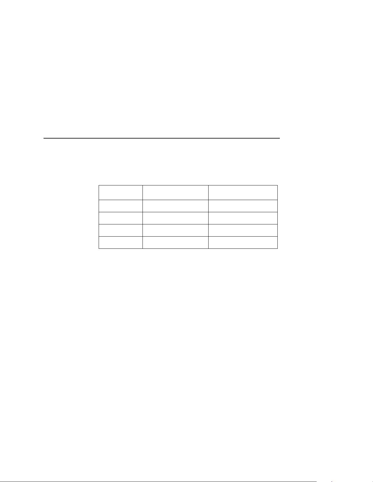
Serial Parameters (RS-232 And RS-422)
The printer uses different response characters to represent buffer
full and buffer empty, depending on whether it is online or offline.
These response characters are listed in the following table:
Online State Buffer State Response Character
Online Buffer Empty CR
Buffer Full 3
Offline Buffer Empty 0
Buffer Full 2
With the SERIES 1, 1 CH protocol selected, if the printer receives a
Series 1 poll character from the host, the printer removes the poll
character from its input data stream and discards it. After a delay,
called the poll delay, the printer replies to the host by sending the
appropriate response character, per the preceding table.
During a poll delay, if the printer receives another poll character,
the printer merely discards it. However, if a transition (from buffer
full to buffer empty or from online to offline) occurs during a poll
delay, the printer sends the response character appropriate to the
new printer state at the end of the delay.
If you enable the Series 1 Idle parameter, then whenever the buffer
is less than 75% full, the printer sends a response character to the
host every two seconds.
You can select the poll character and the poll delay time from the
printer control panel. You can also enable or disable Series 1 Idle
from the control panel. Descriptions of these parameters start on
page 90.
NOTE: When using the SERIES 1, 1 CH protocol, be careful with
the transmission of binary data (control codes, bit images,
etc.) since the printer discards poll characters.
91
Page 92

Chapter 3 Printer Configuration
SERIES 1, 2 CH
When you select the Series 1 with 2 Characters protocol, the printer
behaves exactly the same as the Series 1 with 1 Character
protocol, except that the printer sends two-character responses to
the host. These response characters are listed in the following
table:
Online State Buffer State Response Characters
Online Buffer Empty 1 CR
Offline Buffer Empty 0 CR
NOTE: When using the SERIES 1, 2 CH protocol, be careful with
the transmission of binary data (control codes, bit images,
etc.) since the printer discards poll characters.
Buffer Full 3 CR
Buffer Full 2 CR
92
Baud Rate
Values: 110 to 256,000.
9600 is the default.
This parameter must be set to match your host computer.
Baud rate is the number of bits, including control bits (start/stop and
parity bits) transferred per second over the interface.
Data Bits
Values: 5 to 8 (default).
This parameter must be set to match your host computer.
Serial interfaces support 5, 6, 7, and 8-bit transfer of data words.
Most use 8-bit data transfer, but this must match the host computer.
Page 93

Serial Parameters (RS-232 And RS-422)
Stop Bits
Values: 1 (default) or 2.
This parameter must be set to match your host computer.
Stop bits signal the end of a transferred serial data word.
Parity
Values: None (default), 0, 1, Even, or Odd.
This parameter must be set to match your host computer.
The host may send a parity bit with every data word. The parity bit
is used for error checking.
DTR Function
Values: On/Offline&Buf (default), True, False or On/Offline.
This parameter must be set to match your host computer.
The DTR Function parameter is part of hardware flow control. This
parameter determines when the printer generates the Data
Terminal Ready (DTR) signal to the host computer. DTR is a status
signal that the printer sends to the host to indicate whether or not
the printer is ready to receive data.
• The True parameter setting causes the printer to continuously
assert the DTR signal.
• The False setting causes the printer to never assert the DTR
signal.
• The On/Offline&Buf setting (the default setting) causes the
printer to assert the DTR signal only when the printer is online
and its internal serial buffer is not full.
• The On/Offline setting causes the printer to assert the DTR
signal whenever either the printer is offline or its internal serial
buffer is full.
93
Page 94

Chapter 3 Printer Configuration
RTS Function
Values: On/Offline&Buf (default), True, False or On/Offline.
This parameter must be set to match your host computer.
The RTS Function parameter is part of hardware flow control. This
parameter determines when the printer generates the Request to
Send (RTS) signal to the host computer. RTS is a status signal that
the printer sends to the host to indicate whether or not the printer is
ready to receive data.
• The True parameter setting causes the printer to continuously
assert the RTS signal.
• The False setting causes the printer to never assert the RTS
signal.
• The On/Offline&Buf setting (the default setting) causes the
printer to assert the RTS signal only when the printer is online
and its internal serial buffer is not full.
• The On/Offline setting causes the printer to assert the RTS
signal whenever either the printer is offline or its internal serial
buffer is full.
94
DTR Polarity
Values: Normal (default) or Inverted.
This parameter must be set to match the DTR signal polarity of your
host computer.
This parameter enables the DTR signal to invert if required for a
particular installation.
RTS Polarity
Values: Normal (default) or Inverted.
This parameter must be set to match the RTS signal polarity of your
host computer.
This parameter enables the RTS signal to invert if required for a
particular installation.
Page 95

Serial Parameters (RS-232 And RS-422)
Buffer Size
Value: 8192 bytes.
This parameter reflects the size in characters of the printer’s data
buffer.
This parameter cannot be changed in the current release of the
emulation software. However, it might be changeable in a future
release.
Number (of) Buffers
Value: 2.
This parameter reflects the number of data buffers in the printer’s
memory.
This parameter cannot be changed in the current release of the
emulation software. However, it might be changeable in a future
release.
FIFO Trigger
Values: None, 1, 4, 8, or 14 (default).
You can specify how many bytes the First In, First Out (FIFO) input
buffer stores before the bytes are sent to the printer’s data buffer.
Diagnostic
Values: None (default), Transmit, or Loopback.
This parameter provides for testing of the serial interface circuits.
Tests include a data transmission test and a serial loopback test
(which requires a loopback plug).
Series 1 Poll
Values: The allowable range is 0 through 255. The default value for
this parameter is 0.
This parameter selects the character that the printer recognizes as
the Series 1 poll character.
95
Page 96

Chapter 3 Printer Configuration
NOTE: This parameter is used only with the SERIES 1, 1 CH and
SERIES 1, 2 CH protocols. See the description of the Host
Protocol menu option on page 90 for more information.
Series 1 Delay
Values: 0+ Msec, 15+ Msec, or 30+ Msec. The default value for
this parameter is 0+ Msec.
This parameter selects the Series 1 delay time, in milliseconds, that
the printer waits prior to sending the Series 1 response to the host.
NOTE: This parameter is used only with the SERIES 1, 1 CH and
SERIES 1, 2 CH protocols. See the description of the Host
Protocol menu option on page 90 for more information.
Series 1 Idle
Values: Enable or Disable. The default value for this parameter is
Disable.
If you enable the Series 1 Idle parameter, then whenever the buffer
is less than 75% full, the printer sends a response character to the
host every two seconds.
96
NOTE: This parameter is used only with the SERIES 1, 1 CH and
SERIES 1, 2 CH protocols. See the description of the Host
Protocol menu option on page 90 for more information.
Page 97

Miscellaneous Menu
Miscellaneous Menu
Miscellaneous
Panel Key
Sound
On*
Off
PTX SETUP
Option*
Setup Parse
Disable*
Enable
Overwrite
Files
Enable*
Disable
Alarm
On*
Off
Setup SFCC
21 h*
(0 - FF)
View File List
File 1
File 2
Etc.
Power-up
State
Online*
Offline
Display
Language
English*
German
French
Italian
Spanish
Dutch
Delete Files
File 1
File 2
Etc
Optimize
and Reboot
* = Factory Default
1
= if installed
Hex Dump
Mode
Disable*
Enable
File System
Print File
List
Panel Key Sound
Panel key sound allows you to configure the printer to beep when
you press a key (switch). The default setting is On.
Alarm
Alarm allows you to configure the printer to beep when a printer
fault condition occurs. The default setting is On.
97
Page 98

Chapter 3 Printer Configuration
Power-up State
Power-up state allows you to configure the printer to power up in
the offline or online state. The default setting is Online.
Hex Dump Mode
Hex dump mode allows you to place the printer into the “hex dump”
mode, in which the printer outputs a hexadecimal data stream. The
purpose of hex dump mode is to see exactly what data is received
by the printer, in order to debug forms, for example.
When enabled, the hex dump mode translates all host interface
data to its hexadecimal equivalent, then prints the hex code and its
printable symbol, if one exists. Figure 5 shows a partial example of
a hex dump.
After the printer enters hex dump mode, all characters it prints
(including any in the printer's input buffer) are printed in two forms:
as a two-symbol hexadecimal code, and as the character's
printable symbol (if it has one). A nonprintable code is printed as a
period [.] symbol. Up to 16 characters can be printed per line of hex
dump printout. While the printer is in hex dump mode, it does not
act upon any control codes, other than to print their hexadecimal
equivalents.
98
The 16 characters printed per line on the hex dump are formatted
so that the 16 printable symbols are printed in columns 1 through
16. The 17th column is blank. Column 18 contains either a p (PI line
active) or a blank (PI not active). Columns 19 and 20 contain the
hexadecimal code for the first character, followed by a blank. The
PI line condition and hexadecimal code for the second character
are printed in columns 22, 23, and 24, followed by a blank. The
third through 16th characters are printed in a similar manner. The
hexadecimal code for the 16th character is printed in columns 78,
79, and 80.
Subsequent printing observes the current setting for skip-over
perforation, form length, and top-of-form position parameters.
Page 99

Miscellaneous Menu
If a fault occurs while printing a hex dump, the printer reverts to the
normal fault state. When the fault is cleared, the printer resumes
printing the hex dump (either a partial line with a form feed, or
nothing at all). Top-of-form remains unaffected.
Figure 5. Sample Hex Dump
To begin a hex dump, first place the printer offline and enable the
Hex Dump Mode option from the control panel. Next, place the
printer online. Finally, send data to the printer from the host
computer. Any data received from the host is “dumped” to the
printout.
To cancel a hex dump, first place the printer offline. Then, disable
the Hex Dump Mode option from the control panel. The paper may
then be advanced to the next top-of-form.
PTX SETUP Options
The PTX SETUP Options menu selection has two submenu
selections: Setup Parse and Setup SFCC.
Setup Parse
Setup Parse allows you to enable or disable PTX SETUP
processing. If Setup Parse is disabled, the printer prints PTX
SETUP commands as regular text. The default setting is Disabled.
Setup SFCC
Setup SFCC sets the Special Function Control Code (SFCC) for
the PTX SETUP functions. The default setting is decimal 33. (!
Character)
99
Page 100

Chapter 3 Printer Configuration
Display Language
Display Language allows you to select the language used for
control panel messages and configuration printouts. The available
choices are English, German, French, Italian, Spanish, or Dutch.
The default setting is English.
File System
Overwrite
Allows you to prevent files from being overwritten by disabling the
overwrite function.
View Files
Displays the list of files in the file system. Pressing the DOWN key
displays the file size.
Delete Files
Displays the list of all files in the file system. Pressing the ENTER
key deletes the file displayed on the front panel.
100
Optimize and Reboot
Reclaims flash space from deleted flash files. After pressing
ENTER, wait for the printer to reboot.
Print File List
Prints a summary of the files stored in flash memory and several
statistics on File System Usage.
 Loading...