

Page 1
R
Page 2

Page 3

P/N 704766–001, Rev C
R
Page 4

Communication Notices
Federal Communications Commission (FCC) Statement:
This equipment has been tested and found to comply with the limits for a
Class A digital device, pursuant to Part 15 of the FCC Rules. These limits are
designed to provide reasonable protection against harmful interference when
the equipment is operated in a commercial environment. This equipment
generates, uses, and can radiate radio frequency energy and, if not installed
and used in accordance with the instruction manual, may cause harmful
interference to radio communications. Operation of this equipment in a
residential area is likely to cause harmful interference, in which case the user
will be required to correct the interference at his own expense.
Properly shielded and grounded cables and connectors must be used in order
to meet FCC emission limits. Printronixr is not responsible for any radio or
television interference caused by using other than recommended cables and
connectors or by unauthorized changes or modifications to this equipment.
Unauthorized changes or modifications could void the user’s authority to
operate the equipment.
This device complies with Part 15 of the FCC Rules. Operation is subject to
the following two conditions: (1) this device may not cause harmful
interference, and (2) this device must accept any interference received,
including interference that may cause undesired operation.
Canadian Department of Communications Compliance Statement:
This Class A digital apparatus meets all requirements of the Canadian
Interference–Causing Equipment Regulations.
Avis de conformité aux normes du ministère des Communications du
Canada:
Cet appareil numérique de la classe A respecte toutes les exigences du
Règlement sur le matériel brouilleur du Canada.
European Union (EC) Electromagnetic Compatibility Directives:
This product is in conformity with the protection requirements of EC Council
Directive 89/336/EEC on the approximation of the laws of the Member
States relating to electromagnetic compatibility. Printronixr cannot accept
responsibility for any failure to satisfy the protection requirements resulting
from a non-recommended modification of the product, including the fitting
of non-Printronixr option cards.
Page 5

Dieses Gerät ist berechtigt in Übereinstimmung mit dem deutschen EMVG
vom 9.Nov.92 das EG–Konformitätszeichen zu furhren.
Properly shielded and grounded cables and connectors must be used in order
to reduce the potential for causing interference to radio and TV
communication and to other electrical or electronic equipment.
This product has been tested and found to comply with limits for Class A
Information Technology Equipment according to CISPR 22/European
Standard EN 55022. The limits for Class A equipment were derived for
commercial and industrial environments to provide reasonable protection
against interference with licensed communication equipment.
Warning: This is a Class A product. In a domestic environment this product
may cause radio interference in which case the user may be required to take
adequate measures.
Dieses Gerät erfüllt die Bedingungen der EN 55022 Klasse A. Für diese
Klasse von Geräten gilt folgende Bestimmung nach dem EMVG:
Geräte dürfen an Orten, für die sie nicht ausreichend entstört sind, nur mit
besonderer Genehmigung des Bundesminesters für Post und
Telekommunikation oder des Bundesamtes für Post und Telekommunikation
betrieben werden. Die Genehmigung wird erteilt, wenn keine
elektromagnetischen Störungen zu erwarten sind.
(Auszug aus dem EMVG vom 9.Nov.92, Para.3, Abs.4)
Hinweis: Dieses Genehmigungsverfahren ist von der Deutschen Bundespost
noch nicht veröffentlict worden.
Printronix, Inc. makes no representations or warranties of any kind regarding
this material, including, but not limited to, implied warranties of
merchantability and fitness for a particular purpose. Printronix, Inc. shall not
be held responsible for errors contained herein or any omissions from this
material or for any damages, whether direct, indirect, incidental or
consequential, in connection with the furnishing, distribution, performance or
use of this material. The information in this manual is subject to change
without notice.
This document contains proprietary information protected by copyright. No
part of this document may be reproduced, copied, translated or incorporated
in any other material in any form or by any means, whether manual, graphic,
electronic, mechanical or otherwise, without the prior written consent of
Printronix, Inc. All rights reserved.
Page 6

Trademark Acknowledgements
Postscript is a trademark of Adobe Systems, Inc.
IBM is a registered trademark of International Business Machines
Corporation.
HP is a registered trademark, and PCL is a trademark of Hewlett-Packard
Company.
Centronics is a registered trademark of Genicom Corporation.
Dataproducts is a registered trademark of Hitachi.
Epson is a registered trademark of Epson Seiko Corporation.
IGP, LinePrinter Plus, and Printronix are registered trademarks, and
DuraFusion, LaserLine, PGL, PSA, and Ribbon Minder are trademarks of
Printronix, Inc.
Magnum and QMS are registered trademarks, and Code V is a trademark of
Quality Micro Systems, Inc.
Microsoft, GW-BASIC, MS, and MS-DOS are registered trademarks, and
QuickBASIC, QBASIC, and Windows are trademarks of Microsoft
Corporation.
This product uses Intellifont Scalable typefaces and Intellifont technology.
Intellifont is a registered trademark of Agfa Division, Miles Incorporated
(Agfa).
CG, Garth Graphic, Intellifont, and Type Director are registered trademarks,
and Shannon and CG Triumvirate are trademarks of Agfa Division, Miles
Incorporated (Agfa). CG Bodoni, CG Century Schoolbook, CG Goudy Old
Style, CG Melliza, Microstyle, CG Omega, and CG Palacio are products of
Agfa Corporation. CG Times, based on Times New Roman under license
from The Monotype Corporation Plc is a product of Agfa.
Univers is a registered trademark of Linotype AG and/or its subsidiaries.
Letraset is a registered trademark, and Aachen, Revue and University Roman
are trademarks of Esselte Pendaflex Corporation.
Futura is a registered trademark of Fundición Tipográfica Neufville, S.A.
Page 7

ITC Avant Garde Gothic, ITC Benguiat, ITC Bookman, ITC Century, ITC
Cheltenham, ITC Clearface, ITC Galliard, ITC Korinna, ITC Lubalin Graph,
ITC Souvenir, ITC Tiepolo, ITC Zapf Chancery, and ITC Zapf Dingbats are
registered trademarks of International Typeface Corporation.
Albertus, Gill Sans, and Times New Roman are registered trademarks, and
Monotype Baskerville is a trademark of The Monotype Corporation Plc,
registered in the U.S. Pat. and TM office and elsewhere.
Hiroshige and Marigold are trademarks of AlphaOmega Typography, Inc.
COPYRIGHT 1996, 2000, PRINTRONIX, INC.
Page 8

Page 9

Volume 1
Table of Contents
1
Introduction
English:
General Safety Precautions 1–2. . . . . . . . . . . . . . . . . . . . . . . . . . . . . . . . . . . . . . . . . . . . . .
Setup Safety Precautions 1–4. . . . . . . . . . . . . . . . . . . . . . . . . . . . . . . . . . . . . . . . . . . . . . .
Safety Label Locations 1–5. . . . . . . . . . . . . . . . . . . . . . . . . . . . . . . . . . . . . . . . . . . . . . . . .
Deutsch:
Allgemeine Sicherheitsvorkehrungen 1–11. . . . . . . . . . . . . . . . . . . . . . . . . . . . . . . . . . . . . .
Sicherheitsvorkehrungen beim Installieren 1–13. . . . . . . . . . . . . . . . . . . . . . . . . . . . . . . . .
Anbringungsorte der Sicherheitsetiketten 1–14. . . . . . . . . . . . . . . . . . . . . . . . . . . . . . . . . . .
About This Manual 1–20. . . . . . . . . . . . . . . . . . . . . . . . . . . . . . . . . . . . . . . . . . . . . . . . . . . .
How to Locate Information 1–20. . . . . . . . . . . . . . . . . . . . . . . . . . . . . . . . . . . . . . . . . .
Safety Notices and Special Information 1–20. . . . . . . . . . . . . . . . . . . . . . . . . . . . . . . . .
Switches and Display Messages 1–21. . . . . . . . . . . . . . . . . . . . . . . . . . . . . . . . . . . . . . .
Related Documents 1–21. . . . . . . . . . . . . . . . . . . . . . . . . . . . . . . . . . . . . . . . . . . . . . . .
Printer Features 1–22. . . . . . . . . . . . . . . . . . . . . . . . . . . . . . . . . . . . . . . . . . . . . . . . . . . . . . .
2
Table of Contents
Setup
Power Requirements 2–2. . . . . . . . . . . . . . . . . . . . . . . . . . . . . . . . . . . . . . . . . . . . . . . . . . .
Select a Site 2–3. . . . . . . . . . . . . . . . . . . . . . . . . . . . . . . . . . . . . . . . . . . . . . . . . . . . . . . . . .
Unpack and Level the Printer 2–6. . . . . . . . . . . . . . . . . . . . . . . . . . . . . . . . . . . . . . . . . . . .
Connect the Cables 2–8. . . . . . . . . . . . . . . . . . . . . . . . . . . . . . . . . . . . . . . . . . . . . . . . . . . .
Power Cord 2–8. . . . . . . . . . . . . . . . . . . . . . . . . . . . . . . . . . . . . . . . . . . . . . . . . . . . . .
Install Signal Cables 2–12. . . . . . . . . . . . . . . . . . . . . . . . . . . . . . . . . . . . . . . . . . . . . . . .
Install the Consumables 2–14. . . . . . . . . . . . . . . . . . . . . . . . . . . . . . . . . . . . . . . . . . . . . . . .
i
Page 10

3
Consumables
Install Consumables (Initial Printer Setup) 3–2. . . . . . . . . . . . . . . . . . . . . . . . . . . . . . . . . .
Install the Photoreceptor Drum 3–3. . . . . . . . . . . . . . . . . . . . . . . . . . . . . . . . . . . . . . .
Add the Developer 3–10. . . . . . . . . . . . . . . . . . . . . . . . . . . . . . . . . . . . . . . . . . . . . . . . .
Install the Developing Unit 3–12. . . . . . . . . . . . . . . . . . . . . . . . . . . . . . . . . . . . . . . . . .
Install the Toner Cartridge 3–16. . . . . . . . . . . . . . . . . . . . . . . . . . . . . . . . . . . . . . . . . . .
Loading Fanfold Paper 3–18. . . . . . . . . . . . . . . . . . . . . . . . . . . . . . . . . . . . . . . . . . . . . .
Loading Cut–sheet Paper 3–21. . . . . . . . . . . . . . . . . . . . . . . . . . . . . . . . . . . . . . . . . . . .
Setting Cassette Paper Size 3–23. . . . . . . . . . . . . . . . . . . . . . . . . . . . . . . . . . . . . . .
Installing Diskettes 3–24. . . . . . . . . . . . . . . . . . . . . . . . . . . . . . . . . . . . . . . . . . . . . . . . .
Setting Power Supply Voltage 3–25. . . . . . . . . . . . . . . . . . . . . . . . . . . . . . . . . . . . . . . .
Replacing Consumables 3–30. . . . . . . . . . . . . . . . . . . . . . . . . . . . . . . . . . . . . . . . . . . . . . . .
Replacing the Photoreceptor Drum 3–31. . . . . . . . . . . . . . . . . . . . . . . . . . . . . . . . . . . .
Replacing the Developer 3–40. . . . . . . . . . . . . . . . . . . . . . . . . . . . . . . . . . . . . . . . . . . .
Replacing the Developing Unit 3–43. . . . . . . . . . . . . . . . . . . . . . . . . . . . . . . . . . . . . . .
4
Replacing the Toner Cartridge 3–50. . . . . . . . . . . . . . . . . . . . . . . . . . . . . . . . . . . . . . . .
Replacing the Waste Toner Bottle 3–53. . . . . . . . . . . . . . . . . . . . . . . . . . . . . . . . . . . . .
Scheduled Maintenance
General Cleaning 4–2. . . . . . . . . . . . . . . . . . . . . . . . . . . . . . . . . . . . . . . . . . . . . . . . . . . . .
Print Quality Problems 4–2. . . . . . . . . . . . . . . . . . . . . . . . . . . . . . . . . . . . . . . . . . . . . .
Maintenance Tools 4–4. . . . . . . . . . . . . . . . . . . . . . . . . . . . . . . . . . . . . . . . . . . . . . . . . . . .
Service Level Page Counts 4–5. . . . . . . . . . . . . . . . . . . . . . . . . . . . . . . . . . . . . . . . . . . . . .
About the Page Counter Software 4–7. . . . . . . . . . . . . . . . . . . . . . . . . . . . . . . . . . . . . . . .
Cleaning Schedule 4–9. . . . . . . . . . . . . . . . . . . . . . . . . . . . . . . . . . . . . . . . . . . . . . . . . . . .
Replacement Schedule 4–10. . . . . . . . . . . . . . . . . . . . . . . . . . . . . . . . . . . . . . . . . . . . . . . . .
Cleaning inside the Front Cover 4–12. . . . . . . . . . . . . . . . . . . . . . . . . . . . . . . . . . . . . . . . . .
Cleaning the Transport Unit 4–16. . . . . . . . . . . . . . . . . . . . . . . . . . . . . . . . . . . . . . . . . . . . .
Cleaning the Paper Feed Section 4–19. . . . . . . . . . . . . . . . . . . . . . . . . . . . . . . . . . . . . . . . .
Cleaning the Photoreceptor Drum 4–21. . . . . . . . . . . . . . . . . . . . . . . . . . . . . . . . . . . . . . . .
Cleaning the Main Charger 4–23. . . . . . . . . . . . . . . . . . . . . . . . . . . . . . . . . . . . . . . . . . . . . .
Cleaning the Pre–charger and Transfer/Separator Charger 4–25. . . . . . . . . . . . . . . . . . . . .
ii
Table of Contents
Page 11

Cleaning the Selfoc Lens (LED Print Head) 4–27. . . . . . . . . . . . . . . . . . . . . . . . . . . . . . . .
Cleaning the Discharge LED 4–29. . . . . . . . . . . . . . . . . . . . . . . . . . . . . . . . . . . . . . . . . . . .
Cleaning the Fuser Unit Cover Glass and Lamp Filter 4–31. . . . . . . . . . . . . . . . . . . . . . . . .
Cleaning the Developing Unit / Replacing Developer 4–34. . . . . . . . . . . . . . . . . . . . . . . . .
Cleaning the Pickup Rollers 4–38. . . . . . . . . . . . . . . . . . . . . . . . . . . . . . . . . . . . . . . . . . . . .
Cleaning the Reverse Rollers 4–40. . . . . . . . . . . . . . . . . . . . . . . . . . . . . . . . . . . . . . . . . . . .
Cleaning the Flash Power Supply Filter 4–42. . . . . . . . . . . . . . . . . . . . . . . . . . . . . . . . . . . .
5
Principles of Operation
Printing System Descriptions 5–3. . . . . . . . . . . . . . . . . . . . . . . . . . . . . . . . . . . . . . . . . . . .
General 5–3. . . . . . . . . . . . . . . . . . . . . . . . . . . . . . . . . . . . . . . . . . . . . . . . . . . . . . . . . .
The Printing Process 5–3. . . . . . . . . . . . . . . . . . . . . . . . . . . . . . . . . . . . . . . . . . . . . . .
How Images are Processed 5–4. . . . . . . . . . . . . . . . . . . . . . . . . . . . . . . . . . . . . . . . . . . . . .
Bit Mapping 5–4. . . . . . . . . . . . . . . . . . . . . . . . . . . . . . . . . . . . . . . . . . . . . . . . . . . . . .
Job Recovery 5–4. . . . . . . . . . . . . . . . . . . . . . . . . . . . . . . . . . . . . . . . . . . . . . . . . . . . .
Photoconduction Section 5–7. . . . . . . . . . . . . . . . . . . . . . . . . . . . . . . . . . . . . . . . . . . . . . .
Discharge 5–7. . . . . . . . . . . . . . . . . . . . . . . . . . . . . . . . . . . . . . . . . . . . . . . . . . . . . . . .
Main Charging 5–7. . . . . . . . . . . . . . . . . . . . . . . . . . . . . . . . . . . . . . . . . . . . . . . . . . . .
Exposure 5–9. . . . . . . . . . . . . . . . . . . . . . . . . . . . . . . . . . . . . . . . . . . . . . . . . . . . . . . . .
Developing Section 5–10. . . . . . . . . . . . . . . . . . . . . . . . . . . . . . . . . . . . . . . . . . . . . . . . . . . .
Developing Unit 5–11. . . . . . . . . . . . . . . . . . . . . . . . . . . . . . . . . . . . . . . . . . . . . . . . . . .
Principles of Developing 5–12. . . . . . . . . . . . . . . . . . . . . . . . . . . . . . . . . . . . . . . . . . . .
Transfer/Separation Section 5–14. . . . . . . . . . . . . . . . . . . . . . . . . . . . . . . . . . . . . . . . . . . . .
Transfer 5–14. . . . . . . . . . . . . . . . . . . . . . . . . . . . . . . . . . . . . . . . . . . . . . . . . . . . . . . . .
Separation 5–14. . . . . . . . . . . . . . . . . . . . . . . . . . . . . . . . . . . . . . . . . . . . . . . . . . . . . . . .
Fixing Section 5–16. . . . . . . . . . . . . . . . . . . . . . . . . . . . . . . . . . . . . . . . . . . . . . . . . . . . . . . .
Preheating 5–16. . . . . . . . . . . . . . . . . . . . . . . . . . . . . . . . . . . . . . . . . . . . . . . . . . . . . . . .
Flash Fixing 5–16. . . . . . . . . . . . . . . . . . . . . . . . . . . . . . . . . . . . . . . . . . . . . . . . . . . . . .
Cleaning Section 5–17. . . . . . . . . . . . . . . . . . . . . . . . . . . . . . . . . . . . . . . . . . . . . . . . . . . . . .
Pre–cleaning Charging 5–17. . . . . . . . . . . . . . . . . . . . . . . . . . . . . . . . . . . . . . . . . . . . . .
Drum Cleaning 5–18. . . . . . . . . . . . . . . . . . . . . . . . . . . . . . . . . . . . . . . . . . . . . . . . . . . .
Table of Contents
iii
Page 12

Paper Feed, Transport, and Output Sections 5–19. . . . . . . . . . . . . . . . . . . . . . . . . . . . . . . . .
Paper Detection 5–20. . . . . . . . . . . . . . . . . . . . . . . . . . . . . . . . . . . . . . . . . . . . . . . . . . .
Paper Loading 5–22. . . . . . . . . . . . . . . . . . . . . . . . . . . . . . . . . . . . . . . . . . . . . . . . . . . .
Paper Transport 5–24. . . . . . . . . . . . . . . . . . . . . . . . . . . . . . . . . . . . . . . . . . . . . . . . . . .
Paper Output 5–25. . . . . . . . . . . . . . . . . . . . . . . . . . . . . . . . . . . . . . . . . . . . . . . . . . . . . .
Paper Parking 5–27. . . . . . . . . . . . . . . . . . . . . . . . . . . . . . . . . . . . . . . . . . . . . . . . . . . . .
Drive System Descriptions 5–28. . . . . . . . . . . . . . . . . . . . . . . . . . . . . . . . . . . . . . . . . . . . . .
Drum Drive 5–29. . . . . . . . . . . . . . . . . . . . . . . . . . . . . . . . . . . . . . . . . . . . . . . . . . . . . .
Developing Roller Drive 5–30. . . . . . . . . . . . . . . . . . . . . . . . . . . . . . . . . . . . . . . . . . . .
Main Unit Feed Roller Drive 5–31. . . . . . . . . . . . . . . . . . . . . . . . . . . . . . . . . . . . . . . . .
Gate Drive 5–32. . . . . . . . . . . . . . . . . . . . . . . . . . . . . . . . . . . . . . . . . . . . . . . . . . . . . . .
Transfer Unit Drive 5–33. . . . . . . . . . . . . . . . . . . . . . . . . . . . . . . . . . . . . . . . . . . . . . . .
Tractor Drive 5–34. . . . . . . . . . . . . . . . . . . . . . . . . . . . . . . . . . . . . . . . . . . . . . . . . . . . .
Perforation Cutter Drive 5–35. . . . . . . . . . . . . . . . . . . . . . . . . . . . . . . . . . . . . . . . . . . . .
Separation Claw Drive 5–36. . . . . . . . . . . . . . . . . . . . . . . . . . . . . . . . . . . . . . . . . . . . . .
Cut–sheet Paper Feed Section Drive 5–37. . . . . . . . . . . . . . . . . . . . . . . . . . . . . . . . . . .
Control System Descriptions 5–38. . . . . . . . . . . . . . . . . . . . . . . . . . . . . . . . . . . . . . . . . . . .
Paper Transport System Monitoring 5–39. . . . . . . . . . . . . . . . . . . . . . . . . . . . . . . . . . .
Motor Rotation Control 5–42. . . . . . . . . . . . . . . . . . . . . . . . . . . . . . . . . . . . . . . . . . . . .
Drum Surface Potential Control 5–49. . . . . . . . . . . . . . . . . . . . . . . . . . . . . . . . . . . . . . .
Toner Density Control 5–50. . . . . . . . . . . . . . . . . . . . . . . . . . . . . . . . . . . . . . . . . . . . . .
Remaining Toner Level Monitoring 5–52. . . . . . . . . . . . . . . . . . . . . . . . . . . . . . . . . . . .
Waste Toner Monitoring 5–53. . . . . . . . . . . . . . . . . . . . . . . . . . . . . . . . . . . . . . . . . . . . .
Head Temperature Monitoring 5–54. . . . . . . . . . . . . . . . . . . . . . . . . . . . . . . . . . . . . . . .
Fuser Temperature Monitoring 5–55. . . . . . . . . . . . . . . . . . . . . . . . . . . . . . . . . . . . . . . .
Developing Bias Adjustment 5–56. . . . . . . . . . . . . . . . . . . . . . . . . . . . . . . . . . . . . . . . .
Operational Sequences 5–57. . . . . . . . . . . . . . . . . . . . . . . . . . . . . . . . . . . . . . . . . . . . . . . . .
Electronics Initialization 5–58. . . . . . . . . . . . . . . . . . . . . . . . . . . . . . . . . . . . . . . . . . . .
Mechanical Initialization 5–60. . . . . . . . . . . . . . . . . . . . . . . . . . . . . . . . . . . . . . . . . . . .
Printing Operations 5–64. . . . . . . . . . . . . . . . . . . . . . . . . . . . . . . . . . . . . . . . . . . . . . . .
Command Operations 5–74. . . . . . . . . . . . . . . . . . . . . . . . . . . . . . . . . . . . . . . . . . . . . . .
iv
Table of Contents
Page 13

6
Electrical and Wire Data
System Configuration 6–2. . . . . . . . . . . . . . . . . . . . . . . . . . . . . . . . . . . . . . . . . . . . . . . . . .
Interconnect diagram 6–3. . . . . . . . . . . . . . . . . . . . . . . . . . . . . . . . . . . . . . . . . . . . . . .
Sensors/Actuators connected to MPU Board 6–5. . . . . . . . . . . . . . . . . . . . . . . . . . . . .
Sensors/Actuators connected to I/O Board 6–6. . . . . . . . . . . . . . . . . . . . . . . . . . . . . .
Input / Output Signals 6–8. . . . . . . . . . . . . . . . . . . . . . . . . . . . . . . . . . . . . . . . . . . . . . . . . .
MPU Board Input/Output Signals 6–9. . . . . . . . . . . . . . . . . . . . . . . . . . . . . . . . . . . . .
I/O Board Input/Output Signals 6–10. . . . . . . . . . . . . . . . . . . . . . . . . . . . . . . . . . . . . . .
Controller Board Input/Output Signals 6–11. . . . . . . . . . . . . . . . . . . . . . . . . . . . . . . . .
Unit Interface 6–12. . . . . . . . . . . . . . . . . . . . . . . . . . . . . . . . . . . . . . . . . . . . . . . . . . . . . . . .
I/O board 6–12. . . . . . . . . . . . . . . . . . . . . . . . . . . . . . . . . . . . . . . . . . . . . . . . . . . . . . . .
LED Array Unit 6–14. . . . . . . . . . . . . . . . . . . . . . . . . . . . . . . . . . . . . . . . . . . . . . . . . . .
Flash Power Supply 6–19. . . . . . . . . . . . . . . . . . . . . . . . . . . . . . . . . . . . . . . . . . . . . . . .
Developing Unit 6–24. . . . . . . . . . . . . . . . . . . . . . . . . . . . . . . . . . . . . . . . . . . . . . . . . . .
High–voltage Power Supply Unit 6–29. . . . . . . . . . . . . . . . . . . . . . . . . . . . . . . . . . . . .
Explanation of Circuits According to Function 6–35. . . . . . . . . . . . . . . . . . . . . . . . . . . . . .
Drum Surface Potential Control Circuit 6–35. . . . . . . . . . . . . . . . . . . . . . . . . . . . . . . . .
Developing Bias Control Circuit 6–37. . . . . . . . . . . . . . . . . . . . . . . . . . . . . . . . . . . . . .
Toner Density Control Circuit 6–39. . . . . . . . . . . . . . . . . . . . . . . . . . . . . . . . . . . . . . . .
Drum Motor Control Circuit 6–41. . . . . . . . . . . . . . . . . . . . . . . . . . . . . . . . . . . . . . . . .
Tractor Motor Control Circuit 6–43. . . . . . . . . . . . . . . . . . . . . . . . . . . . . . . . . . . . . . . .
Main Unit Feed Motor Control Circuit 6–46. . . . . . . . . . . . . . . . . . . . . . . . . . . . . . . . .
Transfer Elevator Motor Control Circuit 6–48. . . . . . . . . . . . . . . . . . . . . . . . . . . . . . . .
Cutter Motor Control Circuit 6–51. . . . . . . . . . . . . . . . . . . . . . . . . . . . . . . . . . . . . . . . .
Adjustments 6–52. . . . . . . . . . . . . . . . . . . . . . . . . . . . . . . . . . . . . . . . . . . . . . . . . . . . . . . . .
Adjusting Power Supply Unit For Flash 6–52. . . . . . . . . . . . . . . . . . . . . . . . . . . . . . . .
Table of Contents
v
Page 14

7
Troubleshooting
Overview 7–3. . . . . . . . . . . . . . . . . . . . . . . . . . . . . . . . . . . . . . . . . . . . . . . . . . . . . . . . . . . .
Jam Detection Sensors 7–3. . . . . . . . . . . . . . . . . . . . . . . . . . . . . . . . . . . . . . . . . . . . . .
Printer Components 7–4. . . . . . . . . . . . . . . . . . . . . . . . . . . . . . . . . . . . . . . . . . . . . . . . . . .
External Views 7–5. . . . . . . . . . . . . . . . . . . . . . . . . . . . . . . . . . . . . . . . . . . . . . . . . . . .
Front View with Cover Removed 7–6. . . . . . . . . . . . . . . . . . . . . . . . . . . . . . . . . . . . .
Rear View with Cover Removed 7–8. . . . . . . . . . . . . . . . . . . . . . . . . . . . . . . . . . . . . .
Component Unit Locations 7–9. . . . . . . . . . . . . . . . . . . . . . . . . . . . . . . . . . . . . . . . . .
System Block Diagram 7–10. . . . . . . . . . . . . . . . . . . . . . . . . . . . . . . . . . . . . . . . . . . . . . . .
Printer Control Menu 7–11. . . . . . . . . . . . . . . . . . . . . . . . . . . . . . . . . . . . . . . . . . . . . . . . . .
Menu Diagram 7–12. . . . . . . . . . . . . . . . . . . . . . . . . . . . . . . . . . . . . . . . . . . . . . . . . . . .
Surface Volts 7–13. . . . . . . . . . . . . . . . . . . . . . . . . . . . . . . . . . . . . . . . . . . . . . . . . . . . .
Bias Volts 7–13. . . . . . . . . . . . . . . . . . . . . . . . . . . . . . . . . . . . . . . . . . . . . . . . . . . . . . . .
LED Time 7–13. . . . . . . . . . . . . . . . . . . . . . . . . . . . . . . . . . . . . . . . . . . . . . . . . . . . . . . .
Cut–sheet X Adj. and Cut–sheet Y Adj. 7–13. . . . . . . . . . . . . . . . . . . . . . . . . . . . . . . .
Fan–fold X Adj. and Fan–fold Y Adj. 7–13. . . . . . . . . . . . . . . . . . . . . . . . . . . . . . . . . .
Reset Toner Full 7–13. . . . . . . . . . . . . . . . . . . . . . . . . . . . . . . . . . . . . . . . . . . . . . . . . . .
Fan–fold Paper Jams 7–14. . . . . . . . . . . . . . . . . . . . . . . . . . . . . . . . . . . . . . . . . . . . . . . . . . .
Paper jam near the tractor 7–14. . . . . . . . . . . . . . . . . . . . . . . . . . . . . . . . . . . . . . . . . . .
Paper jam near the paper output section 7–15. . . . . . . . . . . . . . . . . . . . . . . . . . . . . . . .
Cut–sheet Paper Jams 7–19. . . . . . . . . . . . . . . . . . . . . . . . . . . . . . . . . . . . . . . . . . . . . . . . . .
Paper jam at the back of the paper cassette 7–19. . . . . . . . . . . . . . . . . . . . . . . . . . . . . .
Paper jam in the transport input section 7–21. . . . . . . . . . . . . . . . . . . . . . . . . . . . . . . . .
Paper jam in the transport output section 7–23. . . . . . . . . . . . . . . . . . . . . . . . . . . . . . . .
Paper jam in the face–up or face–down paper path 7–24. . . . . . . . . . . . . . . . . . . . . . . .
Error Message Table 7–25. . . . . . . . . . . . . . . . . . . . . . . . . . . . . . . . . . . . . . . . . . . . . . . . . . .
01 – Front Cover Open 7–31. . . . . . . . . . . . . . . . . . . . . . . . . . . . . . . . . . . . . . . . . . . . . . . . .
02 – Paper Empty (fan–fold paper): Upon Power–on 7–32. . . . . . . . . . . . . . . . . . . . . . . . .
02 – Paper Empty (fan–fold paper): When Loading/Beginning Print 7–33. . . . . . . . . . . . .
03 – Paper Jam at Drum (B) 7–34. . . . . . . . . . . . . . . . . . . . . . . . . . . . . . . . . . . . . . . . . . . . .
04 – Paper Jam at Fuser (C): Transport Section 7–36. . . . . . . . . . . . . . . . . . . . . . . . . . . . . .
vi
Table of Contents
Page 15

05 – Paper Jam at Fuser (D): Paper Output Section 7–37. . . . . . . . . . . . . . . . . . . . . . . . . . .
07 – Scuff Lever Open 7–39. . . . . . . . . . . . . . . . . . . . . . . . . . . . . . . . . . . . . . . . . . . . . . . . .
08 – Cut–sheet Path Open 7–40. . . . . . . . . . . . . . . . . . . . . . . . . . . . . . . . . . . . . . . . . . . . . . .
09 – Transport Motor Fail (complete stop) 7–41. . . . . . . . . . . . . . . . . . . . . . . . . . . . . . . . . .
0A – Cutter Fail (front) 7–44. . . . . . . . . . . . . . . . . . . . . . . . . . . . . . . . . . . . . . . . . . . . . . . . .
0B – Cutter Fail (rear) 7–44. . . . . . . . . . . . . . . . . . . . . . . . . . . . . . . . . . . . . . . . . . . . . . . . . .
0C – Transfer Platform Fail (upper) 7–46. . . . . . . . . . . . . . . . . . . . . . . . . . . . . . . . . . . . . . .
0D – Transfer Platform Fail (lower) 7–46. . . . . . . . . . . . . . . . . . . . . . . . . . . . . . . . . . . . . . .
11 – Paper Jam at Drum (B) 7–49. . . . . . . . . . . . . . . . . . . . . . . . . . . . . . . . . . . . . . . . . . . . .
12 – Paper Jam at Fuser (C) 7–50. . . . . . . . . . . . . . . . . . . . . . . . . . . . . . . . . . . . . . . . . . . . .
13 – Paper Jam at Exit (D): Straight Output (face–up) 7–51. . . . . . . . . . . . . . . . . . . . . . . .
13 – Paper Jam at Exit (D): Cut–sheet Face–down Output 7–52. . . . . . . . . . . . . . . . . . . . .
14 – Tractor Speed Too High 7–53. . . . . . . . . . . . . . . . . . . . . . . . . . . . . . . . . . . . . . . . . . . .
15 – Tractor Speed Too Low 7–53. . . . . . . . . . . . . . . . . . . . . . . . . . . . . . . . . . . . . . . . . . . .
16 – Paper Jam at Entrance (A) 7–56. . . . . . . . . . . . . . . . . . . . . . . . . . . . . . . . . . . . . . . . . .
17 – High Voltage Fail 7–57. . . . . . . . . . . . . . . . . . . . . . . . . . . . . . . . . . . . . . . . . . . . . . . . .
18 – Drum Motor Fail (complete stop) 7–59. . . . . . . . . . . . . . . . . . . . . . . . . . . . . . . . . . . . .
19 – Surface Voltage Too High 7–62. . . . . . . . . . . . . . . . . . . . . . . . . . . . . . . . . . . . . . . . . . .
1A – Surface Voltage Too Low 7–63. . . . . . . . . . . . . . . . . . . . . . . . . . . . . . . . . . . . . . . . . . .
1B – Paper Jam at Entrance (A) 7–65. . . . . . . . . . . . . . . . . . . . . . . . . . . . . . . . . . . . . . . . . .
1E – Fuser Supply Fail 7–66. . . . . . . . . . . . . . . . . . . . . . . . . . . . . . . . . . . . . . . . . . . . . . . . .
1F – Fuser Failure 7–68. . . . . . . . . . . . . . . . . . . . . . . . . . . . . . . . . . . . . . . . . . . . . . . . . . . . .
20 – Fuser Lamp Overheat 7–70. . . . . . . . . . . . . . . . . . . . . . . . . . . . . . . . . . . . . . . . . . . . . .
26 – No Cleaning Unit 7–73. . . . . . . . . . . . . . . . . . . . . . . . . . . . . . . . . . . . . . . . . . . . . . . . .
28 – Waste Toner Full 7–74. . . . . . . . . . . . . . . . . . . . . . . . . . . . . . . . . . . . . . . . . . . . . . . . . .
29 – No Waste Toner Box 7–75. . . . . . . . . . . . . . . . . . . . . . . . . . . . . . . . . . . . . . . . . . . . . . .
2A – Toner Empty 7–76. . . . . . . . . . . . . . . . . . . . . . . . . . . . . . . . . . . . . . . . . . . . . . . . . . . . .
2B – Toner Density Too High 7–78. . . . . . . . . . . . . . . . . . . . . . . . . . . . . . . . . . . . . . . . . . . .
2C – Toner Density Too Low 7–78. . . . . . . . . . . . . . . . . . . . . . . . . . . . . . . . . . . . . . . . . . . .
32 – LED Head Overheat 7–80. . . . . . . . . . . . . . . . . . . . . . . . . . . . . . . . . . . . . . . . . . . . . . .
Table of Contents
vii
Page 16

8
Engine Checker
Overview 8–2. . . . . . . . . . . . . . . . . . . . . . . . . . . . . . . . . . . . . . . . . . . . . . . . . . . . . . . . . . . .
Connecting the Engine Checker 8–3. . . . . . . . . . . . . . . . . . . . . . . . . . . . . . . . . . . . . . . . . .
Using the Control Panel 8–4. . . . . . . . . . . . . . . . . . . . . . . . . . . . . . . . . . . . . . . . . . . . . . . .
Operation 8–5. . . . . . . . . . . . . . . . . . . . . . . . . . . . . . . . . . . . . . . . . . . . . . . . . . . . . . . .
Basic Menu 8–6. . . . . . . . . . . . . . . . . . . . . . . . . . . . . . . . . . . . . . . . . . . . . . . . . . . . . . . . . .
Device Check Menu 8–7. . . . . . . . . . . . . . . . . . . . . . . . . . . . . . . . . . . . . . . . . . . . . . . . . . .
Selecting a Mode/Item/Device 8–13. . . . . . . . . . . . . . . . . . . . . . . . . . . . . . . . . . . . . . . .
Reading Device Status (input device check) 8–14. . . . . . . . . . . . . . . . . . . . . . . . . . . . .
Driving/Stopping a Device (output device check) 8–14. . . . . . . . . . . . . . . . . . . . . . . . .
Volume Adjustment Menu 8–17. . . . . . . . . . . . . . . . . . . . . . . . . . . . . . . . . . . . . . . . . . . . . .
Surface Potential 8–18. . . . . . . . . . . . . . . . . . . . . . . . . . . . . . . . . . . . . . . . . . . . . . . . . .
Eraser Lamp 8–18. . . . . . . . . . . . . . . . . . . . . . . . . . . . . . . . . . . . . . . . . . . . . . . . . . . . . .
Drum Motor 8–18. . . . . . . . . . . . . . . . . . . . . . . . . . . . . . . . . . . . . . . . . . . . . . . . . . . . . .
Feed Motor 8–18. . . . . . . . . . . . . . . . . . . . . . . . . . . . . . . . . . . . . . . . . . . . . . . . . . . . . . .
9
Tractor Motor 8–19. . . . . . . . . . . . . . . . . . . . . . . . . . . . . . . . . . . . . . . . . . . . . . . . . . . . .
Toner Density 8–19. . . . . . . . . . . . . . . . . . . . . . . . . . . . . . . . . . . . . . . . . . . . . . . . . . . . .
Basic Operation Menu 8–20. . . . . . . . . . . . . . . . . . . . . . . . . . . . . . . . . . . . . . . . . . . . . . . . .
Fan–fold Paper 8–21. . . . . . . . . . . . . . . . . . . . . . . . . . . . . . . . . . . . . . . . . . . . . . . . . . . .
Cut–sheet Paper 8–21. . . . . . . . . . . . . . . . . . . . . . . . . . . . . . . . . . . . . . . . . . . . . . . . . . .
Memory Operation Menu 8–22. . . . . . . . . . . . . . . . . . . . . . . . . . . . . . . . . . . . . . . . . . . . . . .
Reading and Changing Data 8–23. . . . . . . . . . . . . . . . . . . . . . . . . . . . . . . . . . . . . . . . . .
Board Adjustments
MPU Board Adjustment 9–2. . . . . . . . . . . . . . . . . . . . . . . . . . . . . . . . . . . . . . . . . . . . . . . .
Adjusting the Feed Motor 9–3. . . . . . . . . . . . . . . . . . . . . . . . . . . . . . . . . . . . . . . . . . .
Setting NVRAM Values 9–4. . . . . . . . . . . . . . . . . . . . . . . . . . . . . . . . . . . . . . . . . . . . .
Checking the Vacuum Fan 9–6. . . . . . . . . . . . . . . . . . . . . . . . . . . . . . . . . . . . . . . . . . .
Checking the Pre–heating Lamp 9–6. . . . . . . . . . . . . . . . . . . . . . . . . . . . . . . . . . . . . .
I/O Board Adjustment 9–7. . . . . . . . . . . . . . . . . . . . . . . . . . . . . . . . . . . . . . . . . . . . . . . . . .
Adjusting the Drum Motor 9–9. . . . . . . . . . . . . . . . . . . . . . . . . . . . . . . . . . . . . . . . . . .
Adjusting the Tractor Motor 9–10. . . . . . . . . . . . . . . . . . . . . . . . . . . . . . . . . . . . . . . . .
viii
Table of Contents
Page 17

Adjusting the Drum Surface Potential Sensor – Procedure 1 9–11. . . . . . . . . . . . . . . .
Adjusting the Drum Surface Potential Sensor – Procedure 2 9–15. . . . . . . . . . . . . . . .
Adjusting the Eraser Lamp Input Voltage 9–16. . . . . . . . . . . . . . . . . . . . . . . . . . . . . . .
Adjusting the Toner/Developer Density Sensor 9–16. . . . . . . . . . . . . . . . . . . . . . . . . . .
Setting Rotary and Dip Switches 9–17. . . . . . . . . . . . . . . . . . . . . . . . . . . . . . . . . . . . . .
Confirming I/O Board Operation 9–19. . . . . . . . . . . . . . . . . . . . . . . . . . . . . . . . . . . . . . . . .
Confirming the Developing Bias Voltage Control Circuit 9–19. . . . . . . . . . . . . . . . . . .
Confirming the Main Charger Current Control Circuit 9–20. . . . . . . . . . . . . . . . . . . .
Confirming the Sleeve Motor Operation 9–21. . . . . . . . . . . . . . . . . . . . . . . . . . . . . . . .
Confirming the Magroll Motor Operation 9–21. . . . . . . . . . . . . . . . . . . . . . . . . . . . . . .
Confirming the Toner Supply Clutch Operation 9–21. . . . . . . . . . . . . . . . . . . . . . . . . .
Confirming the Head Cooling Fan Operation 9–22. . . . . . . . . . . . . . . . . . . . . . . . . . . .
Confirming the Head Blower Fan Operation 9–22. . . . . . . . . . . . . . . . . . . . . . . . . . . . .
Confirming the Drum Counter Operation 9–22. . . . . . . . . . . . . . . . . . . . . . . . . . . . . . .
DC Power Supply Board 9–23. . . . . . . . . . . . . . . . . . . . . . . . . . . . . . . . . . . . . . . . . . . . . . .
Index
Table of Contents
ix
Page 18

Volume 2
Table of Contents
10
Replacement Procedures
Overview 10–3. . . . . . . . . . . . . . . . . . . . . . . . . . . . . . . . . . . . . . . . . . . . . . . . . . . . . . . . . . . .
Covers 10–4. . . . . . . . . . . . . . . . . . . . . . . . . . . . . . . . . . . . . . . . . . . . . . . . . . . . . . . . . . . . . .
Front Cover 10–5. . . . . . . . . . . . . . . . . . . . . . . . . . . . . . . . . . . . . . . . . . . . . . . . . . . . . .
Rear Cover 10–6. . . . . . . . . . . . . . . . . . . . . . . . . . . . . . . . . . . . . . . . . . . . . . . . . . . . . . .
Top Cover 10–10. . . . . . . . . . . . . . . . . . . . . . . . . . . . . . . . . . . . . . . . . . . . . . . . . . . . . . . .
Stand Cover 10–13. . . . . . . . . . . . . . . . . . . . . . . . . . . . . . . . . . . . . . . . . . . . . . . . . . . . . .
Inside the Front Cover 10–14. . . . . . . . . . . . . . . . . . . . . . . . . . . . . . . . . . . . . . . . . . . . . . . . .
Waste Toner Recovery Unit 10–15. . . . . . . . . . . . . . . . . . . . . . . . . . . . . . . . . . . . . . . . . .
Developing Unit 10–21. . . . . . . . . . . . . . . . . . . . . . . . . . . . . . . . . . . . . . . . . . . . . . . . . . .
Toner Cartridge 10–21. . . . . . . . . . . . . . . . . . . . . . . . . . . . . . . . . . . . . . . . . . . . . . . . . . .
Photoreceptor Drum and Peripheral Equipment 10–21. . . . . . . . . . . . . . . . . . . . . . . . . .
Fuser Unit 10–28. . . . . . . . . . . . . . . . . . . . . . . . . . . . . . . . . . . . . . . . . . . . . . . . . . . . . . . .
Transfer/Transport Unit 10–32. . . . . . . . . . . . . . . . . . . . . . . . . . . . . . . . . . . . . . . . . . . . .
Inside the Rear Cover 10–41. . . . . . . . . . . . . . . . . . . . . . . . . . . . . . . . . . . . . . . . . . . . . . . . . .
MPU Board and I/O Board 10–41. . . . . . . . . . . . . . . . . . . . . . . . . . . . . . . . . . . . . . . . . .
DC Power Supply Board 10–43. . . . . . . . . . . . . . . . . . . . . . . . . . . . . . . . . . . . . . . . . . . .
Motors 10–46. . . . . . . . . . . . . . . . . . . . . . . . . . . . . . . . . . . . . . . . . . . . . . . . . . . . . . . . . .
Fans 10–56. . . . . . . . . . . . . . . . . . . . . . . . . . . . . . . . . . . . . . . . . . . . . . . . . . . . . . . . . . . .
Solenoids 10–59. . . . . . . . . . . . . . . . . . . . . . . . . . . . . . . . . . . . . . . . . . . . . . . . . . . . . . . .
Miscellaneous 10–60. . . . . . . . . . . . . . . . . . . . . . . . . . . . . . . . . . . . . . . . . . . . . . . . . . . . .
Under the Top Cover 10–69. . . . . . . . . . . . . . . . . . . . . . . . . . . . . . . . . . . . . . . . . . . . . . . . . . .
LED Array Unit 10–70. . . . . . . . . . . . . . . . . . . . . . . . . . . . . . . . . . . . . . . . . . . . . . . . . . .
High–voltage Power Supply Unit 10–73. . . . . . . . . . . . . . . . . . . . . . . . . . . . . . . . . . . . .
Cutter Unit 10–74. . . . . . . . . . . . . . . . . . . . . . . . . . . . . . . . . . . . . . . . . . . . . . . . . . . . . . .
Sensors/Switches 10–77. . . . . . . . . . . . . . . . . . . . . . . . . . . . . . . . . . . . . . . . . . . . . . . . . .
Gates 10–82. . . . . . . . . . . . . . . . . . . . . . . . . . . . . . . . . . . . . . . . . . . . . . . . . . . . . . . . . . . .
Behind the Stand Cover 10–83. . . . . . . . . . . . . . . . . . . . . . . . . . . . . . . . . . . . . . . . . . . . . . . .
Smoke Filter 10–83. . . . . . . . . . . . . . . . . . . . . . . . . . . . . . . . . . . . . . . . . . . . . . . . . . . . . .
x
Table of Contents
Page 19

Flash Power Supply Unit 10–85. . . . . . . . . . . . . . . . . . . . . . . . . . . . . . . . . . . . . . . . . . . .
Capacitors 10–89. . . . . . . . . . . . . . . . . . . . . . . . . . . . . . . . . . . . . . . . . . . . . . . . . . . . . . . .
Other 10–92. . . . . . . . . . . . . . . . . . . . . . . . . . . . . . . . . . . . . . . . . . . . . . . . . . . . . . . . . . . . . . .
Tractor Removal 10–92. . . . . . . . . . . . . . . . . . . . . . . . . . . . . . . . . . . . . . . . . . . . . . . . . . .
Tractor Adjustment Procedure 10–94. . . . . . . . . . . . . . . . . . . . . . . . . . . . . . . . . . . . . . . .
Paper Back–Feed Sensor 10–98. . . . . . . . . . . . . . . . . . . . . . . . . . . . . . . . . . . . . . . . . . . .
Paper Near–End Sensor 10–98. . . . . . . . . . . . . . . . . . . . . . . . . . . . . . . . . . . . . . . . . . . . .
Control Panel 10–99. . . . . . . . . . . . . . . . . . . . . . . . . . . . . . . . . . . . . . . . . . . . . . . . . . . . .
Controller Module 10–100. . . . . . . . . . . . . . . . . . . . . . . . . . . . . . . . . . . . . . . . . . . . . . . . . . . .
Printer Rear Cover 10–101. . . . . . . . . . . . . . . . . . . . . . . . . . . . . . . . . . . . . . . . . . . . . . . . .
Motherboard 10–103. . . . . . . . . . . . . . . . . . . . . . . . . . . . . . . . . . . . . . . . . . . . . . . . . . . . . .
Power Supply 10–105. . . . . . . . . . . . . . . . . . . . . . . . . . . . . . . . . . . . . . . . . . . . . . . . . . . . .
Cooling Fan 10–107. . . . . . . . . . . . . . . . . . . . . . . . . . . . . . . . . . . . . . . . . . . . . . . . . . . . . .
Floppy Disk Drives 10–109. . . . . . . . . . . . . . . . . . . . . . . . . . . . . . . . . . . . . . . . . . . . . . . .
A
B
Specifications
Replacement Schedule A–2. . . . . . . . . . . . . . . . . . . . . . . . . . . . . . . . . . . . . . . . . . . . . . . . .
Replacement Intervals A–3. . . . . . . . . . . . . . . . . . . . . . . . . . . . . . . . . . . . . . . . . . . . . . . . . .
Basic Specifications A–4. . . . . . . . . . . . . . . . . . . . . . . . . . . . . . . . . . . . . . . . . . . . . . . . . . .
Paper Specifications A–5. . . . . . . . . . . . . . . . . . . . . . . . . . . . . . . . . . . . . . . . . . . . . . . . . . .
Host Interface A–5. . . . . . . . . . . . . . . . . . . . . . . . . . . . . . . . . . . . . . . . . . . . . . . . . . . . . . . .
Emulations A–5. . . . . . . . . . . . . . . . . . . . . . . . . . . . . . . . . . . . . . . . . . . . . . . . . . . . . . . . . .
Performance Characteristics A–6. . . . . . . . . . . . . . . . . . . . . . . . . . . . . . . . . . . . . . . . . . . . .
Memory Requirements A–7. . . . . . . . . . . . . . . . . . . . . . . . . . . . . . . . . . . . . . . . . . . . . . . . .
Safety Regulations A–7. . . . . . . . . . . . . . . . . . . . . . . . . . . . . . . . . . . . . . . . . . . . . . . . . . . .
Electromagnetic Interference A–7. . . . . . . . . . . . . . . . . . . . . . . . . . . . . . . . . . . . . . . . . . . .
Physical Characteristics and Environment A–8. . . . . . . . . . . . . . . . . . . . . . . . . . . . . . . . . .
Metric Conversion Tables
Table of Contents
xi
Page 20

C
Illustrated Parts List
Overview C–3. . . . . . . . . . . . . . . . . . . . . . . . . . . . . . . . . . . . . . . . . . . . . . . . . . . . . . . . . . . .
Maintenance Tools C–4. . . . . . . . . . . . . . . . . . . . . . . . . . . . . . . . . . . . . . . . . . . . . . . . .
Parts List by Description C–5. . . . . . . . . . . . . . . . . . . . . . . . . . . . . . . . . . . . . . . . . . . .
Front View of Printer C–14. . . . . . . . . . . . . . . . . . . . . . . . . . . . . . . . . . . . . . . . . . . . . . . . . .
Printer Front Cover Assembly Open C–16. . . . . . . . . . . . . . . . . . . . . . . . . . . . . . . . . . . . . .
Developer Assembly C–18. . . . . . . . . . . . . . . . . . . . . . . . . . . . . . . . . . . . . . . . . . . . . . . . . . .
Miscellaneous Details C–20. . . . . . . . . . . . . . . . . . . . . . . . . . . . . . . . . . . . . . . . . . . . . . . . . .
Cleaning Assembly & Photoreceptor Drum C–22. . . . . . . . . . . . . . . . . . . . . . . . . . . . . . . . .
Transfer Assembly C–24. . . . . . . . . . . . . . . . . . . . . . . . . . . . . . . . . . . . . . . . . . . . . . . . . . . .
Fuser Assembly C–28. . . . . . . . . . . . . . . . . . . . . . . . . . . . . . . . . . . . . . . . . . . . . . . . . . . . . .
Base, WT Assembly (Waste Toner) C–34. . . . . . . . . . . . . . . . . . . . . . . . . . . . . . . . . . . . . . .
Back View of Printer C–36. . . . . . . . . . . . . . . . . . . . . . . . . . . . . . . . . . . . . . . . . . . . . . . . . .
Back View of Printer, Closup C–38. . . . . . . . . . . . . . . . . . . . . . . . . . . . . . . . . . . . . . . . . . . .
Cut Sheet Output Assembly C–44. . . . . . . . . . . . . . . . . . . . . . . . . . . . . . . . . . . . . . . . . . . . .
LED Array C–46. . . . . . . . . . . . . . . . . . . . . . . . . . . . . . . . . . . . . . . . . . . . . . . . . . . . . . . . . .
Cut Sheet Feeder Assembly C–48. . . . . . . . . . . . . . . . . . . . . . . . . . . . . . . . . . . . . . . . . . . . .
Front View, Left Side C–54. . . . . . . . . . . . . . . . . . . . . . . . . . . . . . . . . . . . . . . . . . . . . . . . . .
I/O Board C–58. . . . . . . . . . . . . . . . . . . . . . . . . . . . . . . . . . . . . . . . . . . . . . . . . . . . . . . . . . .
PNE Sensor Assembly (Paper Near–End Sensor Assembly) C–60. . . . . . . . . . . . . . . . . . . .
Controller Module Assembly C–62. . . . . . . . . . . . . . . . . . . . . . . . . . . . . . . . . . . . . . . . . . . .
Head Blower Fan Assembly C–68. . . . . . . . . . . . . . . . . . . . . . . . . . . . . . . . . . . . . . . . . . . . .
Developer Drive Assembly C–70. . . . . . . . . . . . . . . . . . . . . . . . . . . . . . . . . . . . . . . . . . . . . .
General Details C–72. . . . . . . . . . . . . . . . . . . . . . . . . . . . . . . . . . . . . . . . . . . . . . . . . . . . . . .
Filter Assembly Box C–76. . . . . . . . . . . . . . . . . . . . . . . . . . . . . . . . . . . . . . . . . . . . . . . . . . .
AC Blower Assembly C–78. . . . . . . . . . . . . . . . . . . . . . . . . . . . . . . . . . . . . . . . . . . . . . . . . .
Power Supply For Flash Lamp C–80. . . . . . . . . . . . . . . . . . . . . . . . . . . . . . . . . . . . . . . . . . .
Miscellaneous Details C–82. . . . . . . . . . . . . . . . . . . . . . . . . . . . . . . . . . . . . . . . . . . . . . . . . .
P/S EU Assembly (Main Power Supply Assembly) C–84. . . . . . . . . . . . . . . . . . . . . . . . . . .
MPU PC Board C–86. . . . . . . . . . . . . . . . . . . . . . . . . . . . . . . . . . . . . . . . . . . . . . . . . . . . . . .
Back View, Left Side C–88. . . . . . . . . . . . . . . . . . . . . . . . . . . . . . . . . . . . . . . . . . . . . . . . . .
Drum Shaft Assembly & Belts C–94. . . . . . . . . . . . . . . . . . . . . . . . . . . . . . . . . . . . . . . . . . .
Duct Flash Assembly C–96. . . . . . . . . . . . . . . . . . . . . . . . . . . . . . . . . . . . . . . . . . . . . . . . . .
xii
Table of Contents
Page 21

Bracket FU Connect Assembly (Fuser Unit Assembly) C–98. . . . . . . . . . . . . . . . . . . . . . . .
Back of Printer, Left Side C–101. . . . . . . . . . . . . . . . . . . . . . . . . . . . . . . . . . . . . . . . . . . . . . .
Installation/Maintenance Tools C–108. . . . . . . . . . . . . . . . . . . . . . . . . . . . . . . . . . . . . . . . . . .
D
Optional Cut Sheet Feeder
Physical Description D–2. . . . . . . . . . . . . . . . . . . . . . . . . . . . . . . . . . . . . . . . . . . . . . . . . . .
Paper Feed Cassette D–5. . . . . . . . . . . . . . . . . . . . . . . . . . . . . . . . . . . . . . . . . . . . . . . . . . .
Setup and Connection D–6. . . . . . . . . . . . . . . . . . . . . . . . . . . . . . . . . . . . . . . . . . . . . . . . . .
Basic Principles D–9. . . . . . . . . . . . . . . . . . . . . . . . . . . . . . . . . . . . . . . . . . . . . . . . . . . . . . .
Drive principle D–10. . . . . . . . . . . . . . . . . . . . . . . . . . . . . . . . . . . . . . . . . . . . . . . . . . . .
Cassette principle D–10. . . . . . . . . . . . . . . . . . . . . . . . . . . . . . . . . . . . . . . . . . . . . . . . . .
Control principles D–11. . . . . . . . . . . . . . . . . . . . . . . . . . . . . . . . . . . . . . . . . . . . . . . . . . . . .
Upper level / Lower level paper size detector sensor D–11. . . . . . . . . . . . . . . . . . . . . .
Paper feed cassettes D–12. . . . . . . . . . . . . . . . . . . . . . . . . . . . . . . . . . . . . . . . . . . . . . . .
Upper level / lower level paper empty sensor (PES1 / PES2) D–13. . . . . . . . . . . . . . . .
Cut sheet feed sensor (PFS), paper register sensor D–13. . . . . . . . . . . . . . . . . . . . . . . .
Paper timing sensor (PTS) D–14. . . . . . . . . . . . . . . . . . . . . . . . . . . . . . . . . . . . . . . . . . .
Cut sheet pick up motor encoder (PME) D–15. . . . . . . . . . . . . . . . . . . . . . . . . . . . . . . .
Cut sheet feed motor encoder (FME) D–16. . . . . . . . . . . . . . . . . . . . . . . . . . . . . . . . . . .
Paper guide interlock switch (ICIL) D–17. . . . . . . . . . . . . . . . . . . . . . . . . . . . . . . . . . . .
Detection Errors D–18. . . . . . . . . . . . . . . . . . . . . . . . . . . . . . . . . . . . . . . . . . . . . . . . . . . . . .
Upper level cassette section error D–18. . . . . . . . . . . . . . . . . . . . . . . . . . . . . . . . . . . . .
Lower level cassette section error D–18. . . . . . . . . . . . . . . . . . . . . . . . . . . . . . . . . . . . .
Transfer unit error D–19. . . . . . . . . . . . . . . . . . . . . . . . . . . . . . . . . . . . . . . . . . . . . . . . .
Unit sequencer section errors D–20. . . . . . . . . . . . . . . . . . . . . . . . . . . . . . . . . . . . . . . . .
Basic Operation D–21. . . . . . . . . . . . . . . . . . . . . . . . . . . . . . . . . . . . . . . . . . . . . . . . . . . . . . .
Cut Sheet Output Unit D–23. . . . . . . . . . . . . . . . . . . . . . . . . . . . . . . . . . . . . . . . . . . . . . . . .
Physical Description D–23. . . . . . . . . . . . . . . . . . . . . . . . . . . . . . . . . . . . . . . . . . . . . . . .
Setup and Connection D–25. . . . . . . . . . . . . . . . . . . . . . . . . . . . . . . . . . . . . . . . . . . . . .
Basic Principles D–28. . . . . . . . . . . . . . . . . . . . . . . . . . . . . . . . . . . . . . . . . . . . . . . . . . .
Table of Contents
xiii
Page 22

E
Optional Power Paper Stacker
Physical Description E–2. . . . . . . . . . . . . . . . . . . . . . . . . . . . . . . . . . . . . . . . . . . . . . . . . . .
Setup and Connection E–6. . . . . . . . . . . . . . . . . . . . . . . . . . . . . . . . . . . . . . . . . . . . . . . . . .
Drive Principles E–13. . . . . . . . . . . . . . . . . . . . . . . . . . . . . . . . . . . . . . . . . . . . . . . . . . . . . .
Feed roller and transfer belt E–13. . . . . . . . . . . . . . . . . . . . . . . . . . . . . . . . . . . . . . . . . .
Swinger E–15. . . . . . . . . . . . . . . . . . . . . . . . . . . . . . . . . . . . . . . . . . . . . . . . . . . . . . . . . .
Assisting Arm E–16. . . . . . . . . . . . . . . . . . . . . . . . . . . . . . . . . . . . . . . . . . . . . . . . . . . . .
Elevator Table E–17. . . . . . . . . . . . . . . . . . . . . . . . . . . . . . . . . . . . . . . . . . . . . . . . . . . .
Control Principles E–18. . . . . . . . . . . . . . . . . . . . . . . . . . . . . . . . . . . . . . . . . . . . . . . . . . . . .
Transfer Unit Paper Sensor (PMS) E–18. . . . . . . . . . . . . . . . . . . . . . . . . . . . . . . . . . . . .
Jam sensor (PPS) E–19. . . . . . . . . . . . . . . . . . . . . . . . . . . . . . . . . . . . . . . . . . . . . . . . . .
Paper surface sensor 1/2 (PSS1/2) E–20. . . . . . . . . . . . . . . . . . . . . . . . . . . . . . . . . . . . .
Stacker full sensor (SFS), Elevator down sensor (EDS) E–21. . . . . . . . . . . . . . . . . . . .
Stacker motor encoder (SME), Elevator motor encoder (EME) E–23. . . . . . . . . . . . . .
Swinger position sensor (SPS), Assisting arm position sensor (APS1) E–24. . . . . . . . .
Elevator Upper limit / Lower limit switches (LIMT1 / LIMT2) E–25. . . . . . . . . . . . . .
Safety sensors 1/2 (SS1/2) E–26. . . . . . . . . . . . . . . . . . . . . . . . . . . . . . . . . . . . . . . . . . .
Elevator keys (ESWA / ESWS / ESWD) E–26. . . . . . . . . . . . . . . . . . . . . . . . . . . . . . . .
Detection Errors E–27. . . . . . . . . . . . . . . . . . . . . . . . . . . . . . . . . . . . . . . . . . . . . . . . . . . . . .
Operator call status error E–27. . . . . . . . . . . . . . . . . . . . . . . . . . . . . . . . . . . . . . . . . . . .
Serviceman call status error E–27. . . . . . . . . . . . . . . . . . . . . . . . . . . . . . . . . . . . . . . . . .
Basic Operation E–28. . . . . . . . . . . . . . . . . . . . . . . . . . . . . . . . . . . . . . . . . . . . . . . . . . . . . . .
Belt Removal Procedures E–30. . . . . . . . . . . . . . . . . . . . . . . . . . . . . . . . . . . . . . . . . . . . . . .
Power Stacker Cover E–30. . . . . . . . . . . . . . . . . . . . . . . . . . . . . . . . . . . . . . . . . . . . . . .
Inside the Left Frame E–32. . . . . . . . . . . . . . . . . . . . . . . . . . . . . . . . . . . . . . . . . . . . . . .
Inside the Right Frame E–36. . . . . . . . . . . . . . . . . . . . . . . . . . . . . . . . . . . . . . . . . . . . . .
Swinger Belts E–40. . . . . . . . . . . . . . . . . . . . . . . . . . . . . . . . . . . . . . . . . . . . . . . . . . . . .
Perforation Beater Belts E–45. . . . . . . . . . . . . . . . . . . . . . . . . . . . . . . . . . . . . . . . . . . . .
Elevator Belt E–50. . . . . . . . . . . . . . . . . . . . . . . . . . . . . . . . . . . . . . . . . . . . . . . . . . . . . .
Stacker Motor E–53. . . . . . . . . . . . . . . . . . . . . . . . . . . . . . . . . . . . . . . . . . . . . . . . . . . . .
xiv
Table of Contents
Page 23

F
Host I/O Interfaces
Overview F–2. . . . . . . . . . . . . . . . . . . . . . . . . . . . . . . . . . . . . . . . . . . . . . . . . . . . . . . . . . . .
Performance Considerations F–4. . . . . . . . . . . . . . . . . . . . . . . . . . . . . . . . . . . . . . . . . . . . .
Centronics Parallel Interface F–6. . . . . . . . . . . . . . . . . . . . . . . . . . . . . . . . . . . . . . . . . . . . .
Centronics Interface Connector Pin Assignments F–6. . . . . . . . . . . . . . . . . . . . . . . . .
Centronics Parallel Interface Signals F–7. . . . . . . . . . . . . . . . . . . . . . . . . . . . . . . . . . .
Centronics Parallel Interface Configuration F–8. . . . . . . . . . . . . . . . . . . . . . . . . . . . . .
Dataproducts Parallel Interface F–9. . . . . . . . . . . . . . . . . . . . . . . . . . . . . . . . . . . . . . . . . . .
Dataproducts Interface Connector Pin Assignments F–9. . . . . . . . . . . . . . . . . . . . . . .
Dataproducts Parallel Interface Signals F–10. . . . . . . . . . . . . . . . . . . . . . . . . . . . . . . . .
Dataproducts Parallel Interface Configuration F–11. . . . . . . . . . . . . . . . . . . . . . . . . . . .
Termination Resistors F–12. . . . . . . . . . . . . . . . . . . . . . . . . . . . . . . . . . . . . . . . . . . . . . . . . .
RS–232 Serial Interface F–13. . . . . . . . . . . . . . . . . . . . . . . . . . . . . . . . . . . . . . . . . . . . . . . .
RS–232 Interface Connector Pin Assignments F–13. . . . . . . . . . . . . . . . . . . . . . . . . . .
RS–232 Serial Interface Signals F–14. . . . . . . . . . . . . . . . . . . . . . . . . . . . . . . . . . . . . . .
Index
RS–232 Serial Interface Configuration F–15. . . . . . . . . . . . . . . . . . . . . . . . . . . . . . . . .
RS–422 Serial Interface F–16. . . . . . . . . . . . . . . . . . . . . . . . . . . . . . . . . . . . . . . . . . . . . . . .
RS–422 Interface Connector Pin Assignments F–16. . . . . . . . . . . . . . . . . . . . . . . . . . .
RS–422 Serial Interface Signals F–18. . . . . . . . . . . . . . . . . . . . . . . . . . . . . . . . . . . . . . .
RS–422 Serial Interface Configuration F–19. . . . . . . . . . . . . . . . . . . . . . . . . . . . . . . . .
Table of Contents
xv
Page 24

xvi
Table of Contents
Page 25

1
Chapter Contents
English:
General Safety Precautions 1–2. . . . . . . . . . . . . . . . . . . . . . . . . . . . . . . . . . . . . . . . . . . . . .
Setup Safety Precautions 1–4. . . . . . . . . . . . . . . . . . . . . . . . . . . . . . . . . . . . . . . . . . . . . . .
Safety Label Locations 1–5. . . . . . . . . . . . . . . . . . . . . . . . . . . . . . . . . . . . . . . . . . . . . . . . .
Deutsch:
Allgemeine Sicherheitsvorkehrungen 1–11. . . . . . . . . . . . . . . . . . . . . . . . . . . . . . . . . . . . . .
Sicherheitsvorkehrungen beim Installieren 1–13. . . . . . . . . . . . . . . . . . . . . . . . . . . . . . . . .
Anbringungsorte der Sicherheitsetiketten 1–14. . . . . . . . . . . . . . . . . . . . . . . . . . . . . . . . . . .
Introduction
About This Manual 1–20. . . . . . . . . . . . . . . . . . . . . . . . . . . . . . . . . . . . . . . . . . . . . . . . . . . .
How to Locate Information 1–20. . . . . . . . . . . . . . . . . . . . . . . . . . . . . . . . . . . . . . . . . .
Safety Notices and Special Information 1–20. . . . . . . . . . . . . . . . . . . . . . . . . . . . . . . . .
Switches and Display Messages 1–21. . . . . . . . . . . . . . . . . . . . . . . . . . . . . . . . . . . . . . .
Related Documents 1–21. . . . . . . . . . . . . . . . . . . . . . . . . . . . . . . . . . . . . . . . . . . . . . . .
Printer Features 1–22. . . . . . . . . . . . . . . . . . . . . . . . . . . . . . . . . . . . . . . . . . . . . . . . . . . . . . .
1–1Introduction
Page 26

General Safety Precautions
This chapter provides safety information for technicians who are installing and
maintaining L5000 Series printers. Installation, initial setup, testing and
maintenance should be performed only by a factory-trained service representative.
The
printer r
The
printer must be connected to a 30 Amp, 250 V
power
switch does
cord to shut off all power to the printer.
When handling the printer, observe the following precautions to avoid accidents and
ensure safe operation:
• Follow all safety notices and instructions printed in this manual and indicated on
the printer.
• Remove packaging materials carefully, and save them for possible future use. If
the printer is powered on without removing all internal tape and packing, the
printer may be damaged.
elies on pr
not shut off all power to the printer
CAUTION
otective devices in the building installation for pr
outlet. The operator
. Y
ou must unplug the power
-accessible
otection.
• Keep combustible materials away from the printer. Dispose of used toner
properly, as it is flammable.
• Be aware of components in the printer that are potentially hazardous or easily
damaged. For example, the fuser unit becomes very hot under normal operating
conditions, and several components use high voltage.
If it is necessary to remove the fuser section after operating the printer, take care
not to touch its metal portions or cover glass.
• Do not touch the following parts, as high voltages are present:
Corona power supply
Flash lamp power supply
• Do not touch the photoreceptor drum surface, due to the hazardous nature of the
material; it is also easily damaged.
• Do not touch the developer roller assembly.
• Do not touch the xenon and halogen lamps or fuser cover glass, as fingerprints on
lamps will absorb heat and cause them to break.
• Do not place magnetically sensitive items near the developer roller assembly, as
it is magnetized.
• Do not place the toner near vinyl material, as the toner melts vinyl chloride.
1–2 Introduction
Page 27

• Before servicing the printer, disconnect its power plug from the power outlet.
• When performing operational checkout with the printer turned ON, use extreme
caution not to let your clothing or hair get caught in the rotating mechanisms.
• Do not block or obstruct any cabinet ventilation slots.
• Make sure that no foreign matter enters the printer, as injury to personnel,
equipment malfunction, or fire may result.
• Do not spill any kind of liquid on the printer. If the printer surface is soiled, use
only cleaning agents and methods approved by the manufacturer.
• Do not lean on or place heavy objects on top of the printer.
• Do not look directly at the flash lamp.
• Turn off the power immediately if the printer emits an unusual noise or smell.
• Lifting and removing the top cover from the main body requires two people (one
person for the paper feed side, the other person for the paper output side).
1–3Introduction
Page 28

Setup Safety Precautions
When installing the printer, observe the following setup precautions:
Printer
• Do not operate the printer in a room that is not properly ventilated. The room
should be at least 1,000 cubic feet with complete air exchange every two hours.
• Make sure nothing rests on the power cord. Do not locate the power cord where
people will walk on it. Do not place the power cord under any carpet.
• Do not splash water onto the printer. This causes deterioration of internal
insulation, and creates a dangerous condition.
• Do not place drinking cups or other objects on the printer.
• Do not jostle the printer.
• Do not let any metallic pieces (e.g., paper clips or staples) fall into the printer.
• Do not turn off the power while the printer is printing.
• Do not open the top cover while the printer is printing. This may cause a paper
jam.
• Do not clean the printer while it is printing.
• Do not use any flammable spray near the printer.
Consumables
• Never stock the printer consumables –
• Keep all consumables packed until they are to be used.
• Read the installation instructions provided with each consumable.
Near an open flame
Where they may be exposed to direct sunlight
In an area that is hot and humid
In an area that is dusty and dirty
(See page A–8 in Appendix A, Specifications.)
1–4 Introduction
Page 29
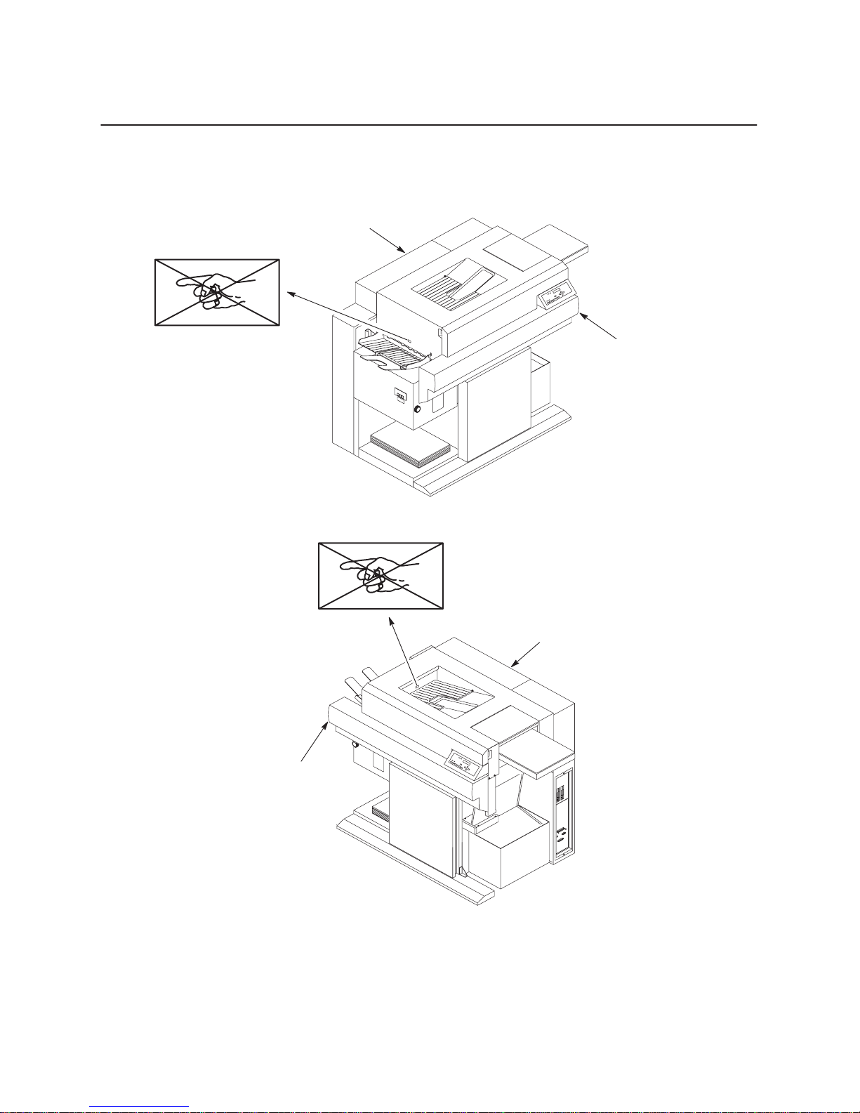
Safety Label Locations
Rear cover
Front upper cover
Front upper cover
Rear cover
Figure 1–1. Safety Labels
1–5Introduction
Page 30
DANGER
Keep your hands away from
tractors while printing.
Printer emits bright light while
printing. Do not stare into
tractor area while printing.
Figure 1–2. Safety Label – Paper Input Side
1–6 Introduction
Page 31

High voltage on
chargers while printing.
DANGER
Hot surface.
Do not touch.
DANGER HOT
Do not touch fuser
unit cover glass.
Figure 1–3. Safety Labels – Front View with Cover Removed
DANGER
1–7Introduction
Page 32

1–8 Introduction
DANGER
Hot surface and hot air.
Avoid contact.
Figure 1–4. Safety Label – Rear Cover
Page 33

DANGER
Keep your hands away from
stacker while printing.
Figure 1–5. Safety Label – Power Paper Stacker (output side)
1–9Introduction
Page 34

DANGER
HIGH VOLTAGE
Do not touch charger
power supply below this
plate.
1–10 Introduction
DANGER HIGH VOLTAGE
Do not touch the varistor on left.
Figure 1–6. Safety Labels – Rear View
Page 35

Allgemeine Sicherheitsvorkehrungen
Dieses Kapitel enthält Sicherheitsinformation für die richtige Installation und
Wartung der L5000 Drucker-Serie. Installation, anfängliches Aufstellen und
Wartung sollten nur von einem durch den Hersteller ausgebildeten
Servicefachmann vorgenommen werden.
VORSICHT
Der Schutz des Druckers beruht auf integrierten Schutzeinrichtungen. Der
Drucker muß an eine 30 A, 250 V Steckdose angeschlossen werden.
Der für den Bediener zugängliche Netzschalter unterbricht die Stromzufuhr
zum Drucker nur teilweise. Das Netzkabel muß ganz herausgezogen sein, um die
Stromzufuhr zum Drucker zu unterbrechen.
Beim Bedienen des Druckers beachten Sie bitte genau die folgenden
Sicherheitsvorkehrungen, um Unfälle zu vermeiden und den sicheren Betrieb des
Druckers zu gewährleisten:
• Befolgen Sie alle Sicherheitshinweise und Anweisungen, die in diesem
Handbuch angeführt oder auf dem Drucker angebracht sind.
• Entfernen Sie das Verpackungsmaterial sorgfältig, und bewahren Sie es für eine
spätere Wiederverwendung auf. Der Drucker könnte beim Einschalten beschädigt
werden, falls Klebebänder und Verpackungsmaterial nicht vollständig vom
Drucker entfernt wurden.
• Halten Sie brennbare Materialien vom Drucker fern. Entsorgen Sie gebrauchten
Toner vorschriftsgemäß. Er ist brennbar.
• Gehen Sie mit den Druckerbestandteilen, die eventuell gefährlich sind oder leicht
beschädigt werden, vorsichtig um. Die Fixiereinheit wird beispielsweise unter
normalen Betriebsbedingungen extrem heiß, und verschiedene Bestandteile
stehen unter hoher Spannung.
Sollte es notwendig sein, dden Bereich der Fixiereinheit nach dem Betrieb des
Druckers zu entfernen, berühren Sie bitte nicht die Metallteile und/oder die
Glasabdeckung.
• Die folgenden Teile nicht berühren, da Sie unter Starkstrom stehen:
Corona Netzteil
Blitzlampennetzteil
• Nicht die Oberfläche der Photorezeptortrommel berühren, da das Material
gesundheitsgefährdend und auch leicht empfindlich ist.
1–11Introduction
Page 36

• Die Entwicklerwalzeinheit nicht berühren.
• Die Xenon- und Halogenlampen sowie die Glasabdeckung des Fixierers nicht
berühren, da Fingerabdrücke Hitze anziehen und die Lampen dadurch platzen.
• Halten Sie magnetisch empfindliche Gegenstände von der Entwicklerwalzeinheit
fern, da sie magnetisiert ist.
• Den Toner nicht in der Nähe von Vinylmaterialien abstellen, da der Toner
Vinylchlorid schmilzt.
• Vor Wartungsarbeiten am Drucker oder bei Einstellungsänderungen den Stecker
immer erst aus der Dose ziehen.
• Wenn Sie den Betrieb des Druckers prüfen wollen, während er angestellt ist,
achten Sie besonders sorgfältig darauf, daß Kleidungsstücke oder Haare nicht in
den Rotationsmechanismus geraten.
• Achten Sie darauf, daß die Gehäuseventilationsschlitze nicht blockiert oder
verstopft sind.
• Achten Sie darauf, daß keine Fremdkörper in den Drucker gelangen. Dies kann
zu Verletzungen des Personals, zu einer Betriebsstörung oder einem Brand
führen.
• Halten Sie jegliche Art von Flüssigkeit vom Drucker fern. Sollte die Oberfläche
des Druckers beschmutzt werden, benutzen Sie nur vom Hersteller empfohlene
Reinigungsmittel und -methoden.
• Lehnen Sie sich nicht auf den Drucker und stellen Sie keine schweren
Gegenstände darauf.
• Schauen Sie nicht direkt in das Blitzlicht.
• Gibt der Drucker ungewühnliche Geräusche oder Gerüche von sich, unterbrechen
Sie sofort die Stromzufuhr.
• Das Heben oder Entfernen der oberen Abdeckung vom Hauptkörper sollte von
zwei Personen vorgenommen werden. (Eine Person auf der Papierzufuhrseite, die
andere auf Papierausgabeseite).
1–12 Introduction
Page 37

Sicherheitsvorkehrungen beim Installieren
Beachten Sie bitte beim Installieren des Druckers die folgenden
Vorsichtsmaßnahmen:
Drucker
• Der Drucker darf nur in einem Raum mit ausreichender Ventialtion eingesetzt
werden. Dieser Raum sollte mindestens 28 Kubikmeter groß sein und
Frischluftzufuhr sollte alle zwei Stunden erfolgen.
• Sorgen Sie dafür, daß keine Gegenstände auf dem Netzkabel abgestellt werden.
Verlegen Sie das Netzkabel so, daß niemand darauf treten kann und daß es nicht
unter einem Teppich liegt.
• Lassen Sie kein Wasser auf den Drucker kommen. Dies kann die interne
Isolierung beschädigen und dadurch einen Gefahrenzustand verursachen.
• Keine Trinkgefäße oder andere Objekte auf dem Printer abstellen.
• Rütteln Sie nicht an dem Drucker.
• Lassen Sie keine Metallstücke (z.B. Büro- oder Heftklammern) in den Drucker
fallen.
• Drehen Sie während des Druckens nicht den Strom ab.
• Öffnen Sie während des Druckens nicht die Abdeckplatte. Dies kann einen
Papierstau zur Folge haben.
• Reinigen Sie den Drucker nicht während des Druckens.
• Benutzen Sie keine feuergefährlichen Sprays in der Nähe des Druckers.
Verbrauchsmaterialien
• Lagern Sie niemals Verbrauchsmaterialien für den Drucker -
in der Nähe einer offenen Flamme
wo sie direktem Sonnenlicht ausgesetzt sind
in einer heißen und feuchten Umgebung
an einem staubigen und schmutzigen Platz
(Siehe Seite A–8 im Anhang A. Angaben.)
• Lassen Sie alle Verbrauchsmaterialien bis zu ihrem Gebrauch in der Verpackung.
• Lesen Sie alle Installationsanweisungen, die mit jedem Verbrauchsgut geliefert
werden.
1–13Introduction
Page 38

Anbringungsorte der Sicherheitsetiketten
Rückseite
Vorderseite
Vorderseite
Abbildung 1–1. Sicherheitsetiketten
Rückseite
1–14 Introduction
Page 39

GEFAHR
Während des Druckvorgangs
Traktoren nicht anfassen.
Drucker emittiert während des
Druckvorgangs helles Licht.
Nicht in den Traktorbereich
schauen.
Abbildung 1–2. Sicherheitsetikette - Seite der Papiereingabe
1–15Introduction
Page 40

GEFAHR
Lader stehen während
des Druckvorgangs
unter hoher Spannung.
GEFAHR
Heiße Oberfläche.
Nicht berühren.
GEFAHR - HEISS
Abdeckglas der
Fixiereinheit
nicht anfassen.
Abbildung 1–3. Sicherheitsetiketten - Vorderansicht bei entfernter Abdeckung
1–16 Introduction
Page 41

Abbildung 1–4. Sicherheitsetikette - Hintere Abdeckung
GEFAHR
Heiße Oberfläche und
heiße Luft. Kontakt
vermeiden.
1–17Introduction
Page 42

VORSICHT
Während des Druckvorgangs
Hände von der automatischen
Papierausgabe fernhalten.
Abbildung 1–5. Sicherheitsetikette - Seite der automatischen Papierausgabe
1–18 Introduction
Page 43

GEFAHR
HOCHSPANNUNG
Netzteil des Laders
unterhalb dieser Platte
nicht berühren.
Abbildung 1–6. Sicherheitsetiketten – Rückansicht
GEFAHR HOCHSPANNUNG
Varistor links nicht berühren.
1–19Introduction
Page 44

About This Manual
This manual explains how to and repair the L5000 Series printers at the field service
level of maintenance. It covers alignments and adjustments, preventive and corrective
maintenance, basic troubleshooting, and principles of operation.
This manual does not explain how to configure or operate the printer. That
information is in the User’s Manual, which supplements this manual.
How to Locate Information
This manual consists of two volumes that are designed so that you can find the
information you need to maintain and repair the printer. You can locate maintenance
information in three ways:
• Use the Table of Contents at the front of Volume 1 and Volume 2.
• Use the Chapter Contents on the first page of each chapter.
• Use the Index at the end of Volume 1 and Volume 2.
Read the entire procedure before beginning any maintenance task. Gather all required
tools and make sure you understand all dangers, cautions, and notes before you begin
working on the printer.
Safety Notices and Special Information
For your safety and to protect valuable equipment, it is very important that you read
and comply with all information highlighted under the following special headings:
DANGER, CAUTION, IMPORTANT, and NOTE. Safety notices that include
conditions that could harm you are written in English and German. (See also the
safety topics in English and German at the beginning of this chapter.)
DANGER
A danger notice calls attention to a condition that could harm you.
CAUTION
A caution notice calls attention to a condition that could harm you or damage
the printer.
1–20 Introduction
Page 45

An important notice provides information that is vital to proper operation of the
printer.
NOTE: A note provides information considered important enough to emphasize.
Switches and Display Messages
In this manual, switches and indicators that are labeled on the printer appear in
uppercase letters.
Control panel display messages also appear in uppercase letters.
Example: “Press the CLEAR switch to take the printer to the OFFLINE READY
state.”
Related Documents
IMPORTANT
For additional information about printer configuration and operation, and optional
interfaces, refer to the following documents:
• L5024 Multifunction Printer User’s Manual (P/N 703718-001)
• L5031 Multifunction Printer User’s Manual (P/N 704765-001)
• Impact Printer Emulation User’s Manual (P/N 703272-001)
• IGP/PGL User’s Manual (P/N 702610-001)
• IGP/VGL User’s Manual (P/N 702611-001)
1–21Introduction
Page 46

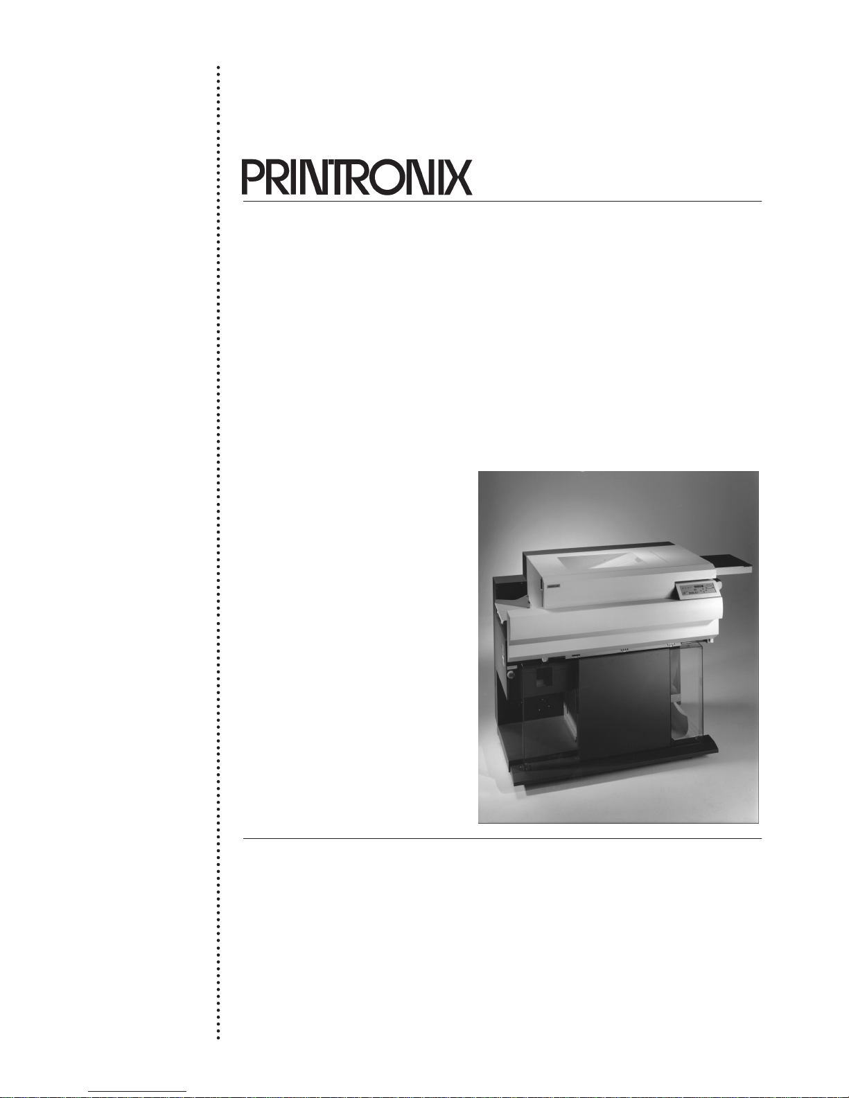
Printer Features
The L5000 Series printer provides the following standard features:
• Non-impact/electrophotographic page printer
The printer is a non-impact page printer that employs the same
electrophotographic system as regular copiers. It meets the needs of users who
wish to produce high-quality prints rapidly and quietly.
• High performance-to-cost ratio
Print speed is 31 pages per minute on continuous 8.5-inch x 11.0-inch forms
(long edge fed), and 24 pages per minute on 8.5-inch x 11.0-inch forms in the
optional cut sheet mode. The low hardware and consumable costs offer higher
cost efficiency than existing competing brands.
• LED exposure system for enhanced printing resolution
Exposure LEDs are arranged at a density equivalent to the printing resolution
(300 dpi standard), and exposure is executed one dot row at a time.
• Two-component developer used for high print quality assurance
The two-component developer contains a synthetic carrier that is resin coated to
weaken its magnetism. This assures that the toner properly adheres to the
Photoreceptor drum surface, depending on the strength of electric and magnetic
fields generated between the photoreceptor drum and developer roller surfaces.
• Supports a wide variety of paper sizes
Either continuous forms or cut-sheet paper can be used. The maximum width of
fan-fold paper that can be used is 16 inches, and various cut-sheet paper sizes up
to ledger size are applicable. The built-in automatic paper parking mechanism
enables switching to the cut-sheet paper mode while fan-fold paper is set in
position.
• Flash fixing system, which works on most paper types
A xenon (Xe) lamp-based, non-contact, flash toner fixing system is employed,
enabling printing on various types of special paper such as mailing and other
adhesive labels. Further, the use of a very simple paper transport system permits
printing onto thick paper having weights up to 44 lb. bond or 125 lb. tag and
label stock.
1–22 Introduction
Page 47

• Small-size and low acoustic noise
Although a flash fixing system is employed, an advanced acoustic noise
reduction feature is incorporated that reduces the acoustic noise emission to a
level that is comparable to that of a thermal roller fixing type laser printer.
Further, the printer size is minimized to permit effective office space utilization.
• PrintronixR System Architecture (PSAt)
The controller is compatible with all requirements of the PSA system. This
means that all PSA compatible emulations (IGP/PGL, IGP/VGL, Lineprinter
Plus, HP PCL5, etc.) can be accommodated, and are configured by exchanging
floppy disks.
• Wide Selection of Host Interfaces
A wide variety of host interfaces are provided. Serial RS-232/422, Centronics
parallel, and Dataproducts parallel (requires optional cable adapter) are standard,
with IBM Coax and Twinax available as options. A serial diagnostic port is also a
standard feature.
• Suitable for wide applications
User needs were analyzed to make the printer capable of satisfying a wide variety
of applications. For example, it can serve as a high-speed, high-quality line
printer, graphics printer, or bar-code printer.
1–23Introduction
Page 48

1–24 Introduction
Page 49

2
Chapter Contents
Power Requirements 2–2. . . . . . . . . . . . . . . . . . . . . . . . . . . . . . . . . . . . . . . . . . . . . . . . . . .
Select a Site 2–3. . . . . . . . . . . . . . . . . . . . . . . . . . . . . . . . . . . . . . . . . . . . . . . . . . . . . . . . . .
Unpack and Level the Printer 2–6. . . . . . . . . . . . . . . . . . . . . . . . . . . . . . . . . . . . . . . . . . . .
Connect the Cables 2–8. . . . . . . . . . . . . . . . . . . . . . . . . . . . . . . . . . . . . . . . . . . . . . . . . . . .
Consumables Installation 2–14. . . . . . . . . . . . . . . . . . . . . . . . . . . . . . . . . . . . . . . . . . . . . . .
Setup
Power Cord 2–8. . . . . . . . . . . . . . . . . . . . . . . . . . . . . . . . . . . . . . . . . . . . . . . . . . . . . .
Signal Cables 2–12. . . . . . . . . . . . . . . . . . . . . . . . . . . . . . . . . . . . . . . . . . . . . . . . . . . . .
Setup
2–1
Page 50

Power Requirements
Do not connect the printer to the power source until instructed to do so and
until all shipping restraints have been removed.
The operator-accessible power switch does not shut off all power to the printer.
Unplug the power cord to shut off all power to the printer.
Drucker nicht an das Netz anschließen, ehe Sie dazu angewiesen werden und
erst nachdem alle Verpackungsmaterialien entfernt worden sind.
Der für den Bediener zugängliche Netzschalter unterbricht die Stromzufuhr
zum Drucker nicht vollständig. Ziehen Sie das Netzkabel heraus, um die
Stromzufuhr zum Drucker vollkommen abzuschalten.
DANGER
GEFAHR
The printer must be connected to either 200, 220 or 240 VAC, single phase, 50-60 Hz
(as shown on the rear side panel label). Otherwise, the printer will not operate
properly and may be damaged.
The printer relies on protective devices in the building installation for protection. The
power source must be properly grounded and rated for at least 30 Amps service.
Since large power fluctuations can cause the printer to malfunction, it should be
connected to a “noise-free” power source, not subject to surges or noise generated by
motors, lighting, or air conditioning equipment on the same circuit. To allow for an
adequate power cable run, the printer should be placed within eight feet (2.5 meters)
of the power source outlet.
For installation in the United States and Canada, the mating connector for the printer
power cord should be a NEMA L6-30P female connector, rated at 250 VAC and 30
Amps.
For international installations, a European harmonized power cord is supplied, which
must be used instead of the UL/CSA power cord.
Instructions for connecting the power cord to the printer are provided on page 2–8.
The choice of cable plugs is determined by the requirements of the country in which
the printer is installed.
2–2
Setup
Page 51

Select a Site
Select a location for the printer that conforms to the following requirements:
• The location has a power source that conforms to the requirements specified on
• The location is within the maximum cable length specifications for the host
• The temperature range is +50°F to +85°F (10°C to 30°C), with a humidity range
• The location must allow 36 inches of space on all sides of the printer.
• Install the printer on a stable horizontal surface. The slope of the floor must not
• The printer should not be exposed to direct sunlight or hot lighting equipment.
page 2–2.
computer interface.
of 30 to 80%. There are no sudden changes in temperature or humidity, and the
printer is positioned away from air drafts caused by heating or air conditioning
ducts.
exceed one degree.
This may cause an abnormal temperature rise in the printer and adversely affect
its operation. Shade or screen the printer from such exposure.
• Do not position the printer near water faucets, water heaters, or refrigerators.
Also avoid dusty locations.
• Do not position the printer near combustibles.
• Do not expose the printer to any corrosive gases or vapors.
• Do not install the printer in an area subject to heavy vibrations.
• Ozone is generated inside the printer. Although the printer contains an ozone
filter, the printer should be installed in a room that provides adequate ventilation.
(The room should be at least 1,000 cubic feet with complete air exchange every
two hours.)
• Lateral openings in the printer are provided for ventilation. To prevent printer
overheating, make sure that these openings are not covered.
Printer dimensions are illustrated on the following pages.
Setup
2–3
Page 52

56.50 in.
(143.5 cm.)
43.50 in.
(110.5 cm.)
57.25
in.
(145.4 cm.)
2–4
Printer Dimensions (In Crate)
Setup
Page 53

50.6 in.
(128.5 cm.)
*
36.0 in.
(91.4 cm.)
36.5 in.
(92.7 cm.)
47.5
(120.7 cm.)
in.
* Leave at least 36 in. (91.4 cm.) around the entire printer.
Setup
Printer Dimensions (Unpacked)
2–5
Page 54

Unpack and Level the Printer
After a site has been selected for the printer, set up the printer according to the
following procedures.
1. Open the packaging, and unpack the printer and consumables, as described in the
Unpacking Instructions.
2. Using the casters, transport the printer to the location where it is to be installed.
Leave space around the printer when setting up, as shown on the previous page.
3. Using the height-adjusting legs, set the bottom of the printer 2.75” ±1//16”
(6.99 cm ± 0.16 cm) from the floor as shown below.
Height Adjusting Leg
Main Body Frame
2.75
in. ±1/16 in.
(6.99 cm ± 0.16 cm)
2–6
Setup
Page 55

4. Put a level on the front cover and the tractor splined shaft, and make fine
adjustments, using the height-adjusting legs, to level the printer in both
directions, as shown below.
Level in the two
directions
Setup
Height Adjusting Legs (4 places)
2–7
Page 56

Connect the Cables
Power Cord
The procedure to install the power cord is identical for both domestic and
international power cords, using the following part numbers:
• P/N 703904-001: for installation in the United States and Canada. The mating
connector for the printer power cord should be a NEMA L6-30P female
connector, rated at 250 VAC and 30 Amps.
• P/N 703904-002: for international installation. A European harmonized power
cord must be used instead of the UL/CSA power cord.
The choice of cable plugs is determined by the requirements of the country in which
the printer is installed.
1. Remove the three screws on the right rear cover.
2–8
Screws (3)
Setup
Page 57

2. Loosen the screw on the connector cover in the lower part of the rear cover, and
slide the connector cover to the left, as shown. Then remove the screw (1) inside
the connector cover.
Connector Cover
Screw (loosen)
Screw (remove)
3. Remove the five screws securing the rear cover.
4. Lift the rear cover one centimeter upward, then remove it.
Rear Cover (right)
Setup
2–9
Page 58

5. Remove the four screws on the power supply terminal box cover. Then remove
the cover.
6. Remove the two screws on the transparent terminal cover inside the box. Then
remove the cover.
Transparent
Terminal Cover
Terminal Box
Cover
Screws (2)
Screws (4)
2–10
Setup
Page 59

7. Connect the power cord to the terminal block. Connect the power cord and
ground wire to each terminal, in the following order: line 1, line 2, and ground
wire. Tighten the nut to lock the power cord in position. The breaker should be
set to “ON,” as shown in the following illustration.
Line 1
Line 2
Ground Wire
Terminal Stand
Nut
Terminal Block
Power Cord
8. Reinstall the transparent terminal cover and the terminal box cover over the
terminal stand, and tighten their screws.
9. Make sure the ON/OFF switch on the printer is set to the OFF position.
10. Attach the appropriate mating connector for the particular service outlet available
to the other end of the power cord. Insure that the connector used meets the
power requirements of the printer. (Refer to “Power Requirements” on
page 2–2.)
11. Do not attach the right rear cover, yet.
Setup
2–11
Page 60

Install Signal Cables
Now the printer can be connected to power and to the computer. To connect the
cables, refer to the illustration on the following page and perform the steps listed
below.
1. Verify that the site line voltage is the same as the voltage specified on the rear
side panel label. (Refer to “Power Requirements” on page 2–2.)
2. Make sure the printer power switch is set to 0 (OFF).
NOTE: To avoid possible electrical interference, separate the AC power cord and
the interface cable.
3. Connect the free end of the power cord to the AC line receptacle.
4. Connect the interface cable to the appropriate printer interface connector and to
the host computer.
NOTE: The printer must be properly configured for the appropriate interface. Refer
to Appendix F, Host I/O Interfaces.
2–12
Setup
Page 61

Power Switch
232/422 Switch
Diskette Drives
1
Parallel
Setup
Serial
1
The RS-232/422 select switch located on the cover plate must be set
Diagnostic Port
properly for your application. The factory default setting is RS-232.
2–13
Page 62

Install the Consumables
After the cables are connected, install the photoreceptor drum, developing unit, and
toner cartridge according to the instructions in Chapter 3, “Consumables.” Perform
all procedures listed under the topic, “Installing Consumables.”
2–14
Setup
Page 63

3
Chapter Contents
Install Consumables (Initial Printer Setup) 3–2. . . . . . . . . . . . . . . . . . . . . . . . . . . . . . . . . .
Consumables
Install the Photoreceptor Drum 3–3. . . . . . . . . . . . . . . . . . . . . . . . . . . . . . . . . . . . . . .
Add the Developer 3–10. . . . . . . . . . . . . . . . . . . . . . . . . . . . . . . . . . . . . . . . . . . . . . . . .
Install the Developing Unit 3–12. . . . . . . . . . . . . . . . . . . . . . . . . . . . . . . . . . . . . . . . . .
Install the Toner Cartridge 3–16. . . . . . . . . . . . . . . . . . . . . . . . . . . . . . . . . . . . . . . . . . .
Loading Fanfold Paper 3–18. . . . . . . . . . . . . . . . . . . . . . . . . . . . . . . . . . . . . . . . . . . . . .
Loading Cut-sheet Paper 3–21. . . . . . . . . . . . . . . . . . . . . . . . . . . . . . . . . . . . . . . . . . . .
Setting Cassette Paper Size 3–23. . . . . . . . . . . . . . . . . . . . . . . . . . . . . . . . . . . . . . .
Installing Diskettes 3–24. . . . . . . . . . . . . . . . . . . . . . . . . . . . . . . . . . . . . . . . . . . . . . . . .
Setting Power Supply Voltage 3–25. . . . . . . . . . . . . . . . . . . . . . . . . . . . . . . . . . . . . . . .
Replacing Consumables 3–30. . . . . . . . . . . . . . . . . . . . . . . . . . . . . . . . . . . . . . . . . . . . . . . .
Replacing the Photoreceptor Drum 3–31. . . . . . . . . . . . . . . . . . . . . . . . . . . . . . . . . . . .
Replacing the Developer 3–40. . . . . . . . . . . . . . . . . . . . . . . . . . . . . . . . . . . . . . . . . . . .
Replacing the Developing Unit 3–43. . . . . . . . . . . . . . . . . . . . . . . . . . . . . . . . . . . . . . .
Replacing the Toner Cartridge 3–50. . . . . . . . . . . . . . . . . . . . . . . . . . . . . . . . . . . . . . . .
Replacing the Waste Toner Bottle 3–53. . . . . . . . . . . . . . . . . . . . . . . . . . . . . . . . . . . . .
Consumables
3–1
Page 64

Installing Consumables
The following procedures should be performed only by an individual who has
received the appropriate training.
To prepare the printer for initial operation, perform the following procedures:
• Install the photoreceptor drum
• Add the developer to the developing unit
• Install the developing unit
• Install the toner cartridge
• Load fan-fold paper
• Load cut-sheet paper (optional)
• Install the diskette(s)
• Set the power supply voltage
IMPORTANT
IMPORTANT
The instructions for the initial installation of consumables are written as a
continuous procedure, where each task builds upon the previous task. For
individual replacement procedures, refer to page 3–30.
3–2
Consumables
Page 65

Install the Photoreceptor Drum
These instructions describe the initial installation of the photoreceptor drum
(P/N 703535-001). (When the drum life of 300,000 pages has been exceeded, the
drum must be replaced. To replace the drum, refer to page 3–31.)
To install the drum, you will need the auxiliary rod (P/N 703531-170). Please read all
steps before beginning the installation process.
Installation of the photoreceptor drum should be performed only by an
individual who has received the appropriate training. Do not attempt this
procedure without the auxiliary rod (P/N 703531-170), as you may damage the
drum.
The photoreceptor drum is light-sensitive. Do not expose the drum to direct
sunlight, and install it within five minutes under typical room lighting
conditions. When removing the drum from its packaging, do not touch the
surface of the drum, due to the hazardous nature of the material. In addition,
fingerprints and scratches can damage the surface and cause poor print quality.
CAUTION
VORSICHT
Die Installation der Photorezeptortrommel sollte nur durch eine Person mit
entsprechender Ausbildung erfolgen. Bitte versuchen Sie diesen Vorgang nicht
ohne die Verwendung der Hilfsstange (P/N 703531-170), da sonst die Trommel
beschädigt werden kann.
Die Photorezeptortrommel ist lichtempfindlich. Setzen Sie die Trommel nicht
dem direkten Sonnenlicht aus und installieren Sie sie innerhalb von fünf
Minuten unter normalen Innenbeleuchtungsbedingungen. Beim Entfernen der
Trommel aus ihrer Verpackung die Trommeloberfläche nicht berühren, da das
Material gesundheitsgefährdend ist. Außerdem können Fingerabdrücke und
Kratzer die Oberfläche beschädigen und verminderte Druckqualität zur Folge
haben.
Consumables
3–3
Page 66

1. As this is the initial printer installation, the power cord should not yet be plugged
in, and the power switch should be OFF. The right rear cover is not attached.
2. Open the printer front upper cover.
Open/Close
Button
Front Cover
3. Open the waste toner recovery unit by pushing downward on the lever. Pull the
green handle and swing the unit outward away from the printer.
Waste Toner
Recovery Unit
Green Handle
Opening Lever
3–4
Consumables
Page 67

4. Remove three screws on the upper inner cover. Then remove the cover.
Upper Inner Cover
CAUTION
Screws (3)
The transfer charger must be in the down position to avoid scratching the drum.
Failure to perform steps 5 and 6 will damage the drum.
5. Check that the transfer charger is in the down position; if it is not, move it to the
down position by rotating the transfer elevator drive shaft counterclockwise.
Watch the charger movement:
a. If the charger starts to move up, it is already in the down position.
b. If the charger starts to move down, continue to rotate the drive shaft until the
charger reaches the complete down position.
Transfer Charger
Consumables
Transfer Elevator
Drive Shaft
3–5
Page 68

6. Lower the transport unit by turning the green lever on the transport unit to the left.
Green Lever
7. Loosen the three thumb screws securing the drum plate and remove the drum
plate.
8. Remove the two screws on the lower inner cover. Then remove the cover.
Drum Plate
Thumb Screws (3)
Screws (2)
Inner cover (lower)
3–6
Consumables
Page 69

9. Remove the nut from the end of the drum shaft.
Drum Shaft
Nut
10. Screw the auxiliary rod onto the drum shaft.
11. Wipe the drum shaft clean with a cloth.
Drum Shaft
Auxiliary rod for
changing the drum,
P/N 703531-170
Consumables
3–7
Page 70

12. Remove the new photoreceptor drum from its package. Do not discard the
packaging material, as it will be needed for future drum disposal.
Note that the sides of the drum are identical; there are no front or back sides.
Wipe inside the end-caps of the drum with a cloth to ensure that they are clean.
DANGER
Exposing the drum to light shortens its life. Do not expose the drum to direct
sunlight, and install it within five minutes under typical room lighting
conditions. When removing the drum from its packaging, do not touch the
surface of the drum, due to the hazardous nature of the material. In addition,
fingerprints and scratches can damage the surface and cause poor print quality.
GEFAHR
Das Aussetzen der Trommel an Licht verkürzt ihre Lebensdauer. Setzen Sie die
Trommel nicht dem direkten Sonnenlicht aus und installieren Sie sie innerhalb
von fünf Minuten unter normalen Innenbeleuchtungsbedingungen. Beim
Entfernen der Trommel aus ihrer Verpackung die Trommeloberfläche nicht
berühren, da das Material gesundheitsgefährdend ist. Außerdem können
Fingerabdrücke und Kratzer die Oberfläche beschädigen und verminderte
Druckqualität zur Folge haben.
CAUTION
Never force the drum onto the shaft. If it feels like the drum does not seat
properly, remove the drum and inspect the shaft for any foreign material or
burrs.
13. Using both hands, carefully slide the drum onto the auxiliary rod. When the drum
reaches the area where the auxiliary rod connects to the drum shaft, lift the drum
very slightly over the connection. Then let the drum rest on the rubber rollers as
you guide it into the printer; the drum must rest on the rollers to avoid being
scratched.
CAUTION
In order to position the drum slot and the drum shaft pin, push the drum in all
the way to the back and rotate it until you feel it drop in place. Failure to lock
the drum in place properly may cause severe damage to the printer.
14. Rotate the photoreceptor drum by hand while applying inward pressure until it
seats securely against the rear of the printer. Then rotate the drum to the right
until it moves slightly further into the printer and locks in place.
3–8
Consumables
Page 71

15. Remove the auxiliary rod from the drum shaft.
16. Install the nut on the drum shaft, and tighten it securely by hand.
17. Install the drum plate and tighten the thumb screws. While installing the drum
plate, place your thumb over the copper grounding clip and hold it in place.
Otherwise the grounding clip can be bent, making no contact with the drum shaft.
18. After installing the drum, measure the resistance. Put the positive lead of a
multimeter on the edge of the drum, and the negative lead on the bracket on the
plate. Normal resistance should be 0Ω.
19. Next, add the developer and install the developing unit, as explained in the
following procedures.
Consumables
3–9
Page 72

Add the Developer
Developer Bottle
Nozzle
Cap
Developing Unit
Screw
Knob
Cover
To add developer to the developing unit for the first time, perform the following
steps. (To replace developer in an existing developing unit, see page 3–40.)
1. Remove the developing unit from its package.
2. Locate the developer bottle.
3. On the developing unit, remove the three cover screws and the cover.
CAUTION
The toner sensor is sensitive to both electrostatic discharge (ESD) and positional
adjustment. Do not touch the sensor with your hand or jar it from its factory-set
position.
4. Shake the developer bottle several times, open the cap, and screw the nozzle on
tightly.
3–10
Consumables
Page 73

Developer Powder
Roller Knob
IMPORTANT
If toner or developer spills on skin or clothing, use cold water to remove it.
5. Pour the entire bottle of developer powder into the developing unit evenly, while
rotating the roller knob counterclockwise.
6. Replace the cover and tighten the screws. Next, install the developing unit as
described in the following procedure.
Consumables
3–11
Page 74

Install the Developing Unit
To install the developing unit for the first time, perform the following steps. (To
replace the developing unit, refer to page 3–43.)
This procedure assumes the following:
• The power switch is OFF.
• The power cord is unplugged.
• The right rear cover is not attached.
• The printer is open with the two inner covers removed, the transfer charger in the
down position, and the transport unit lowered.
• You have installed the drum.
• You have added developer to the developing unit.
Failure to perform Step 1 will damage the photoreceptor drum.
CAUTION
1. On the developing unit, rotate the lever fully clockwise so that it is pointing
straight up.
2. Holding the lever in one hand and the hanger in the other hand, insert the
developing unit on the guide rail.
Guide Rail
Hanger
Lever
3–12
Consumables
Page 75

3. Rotate the hanger to the right so that it rests against the developing unit, and push
the developing unit in.
4. Rotate the developing roller knob counterclockwise until the unit drops into its
final resting position. The positioning pin should protrude through the main body
of the developing unit.
Positioning Pin
Lever
Developing
Roller Knob
5. Rotate the developing unit lever fully counterclockwise to lock the developing
unit in place.
Consumables
3–13
Page 76

6. Raise the transport unit: while pressing the transport unit in, turn the green lever
to the right to lock the transport unit in place.
Green Lever
7. Install the lower inner cover, and secure it with the two screws.
Lower Inner
Cover
Screws (2)
3–14
Consumables
Page 77

8. Install the upper inner cover, and secure it with the three screws.
Upper Inner Cover
Screws (3)
9. Close the waste toner recovery unit and ensure that it latches.
10. Next, install the toner cartridge as discussed in the following procedure.
Consumables
3–15
Page 78

Install the Toner Cartridge
To install the toner cartridge for the first time, perform the following steps. (To
replace the toner cartridge when the message “Toner Empty” is displayed on the
control panel, refer to page 3–50.)
This procedure assumes the following:
• The power switch is OFF.
• The power cord is unplugged.
• The right rear cover is not attached.
• The printer front upper cover is open.
• You have installed the drum.
• You have added developer to the developing unit and installed the unit.
NOTE: When installing the toner cartridge, wear vinyl gloves to prevent toner from
contacting the skin. If necessary, use only cold water to remove from skin or
clothing.
1. Keep the toner cartridge in its package. Holding it level, shake it back and forth
three or four times as shown by the arrows. This loosens the toner in the
cartridge.
Toner Cartridge
2. Remove the toner cartridge from its package.
3–16
Consumables
Page 79

3. With the cover tape facing up, begin inserting the cartridge into the toner hopper,
and slowly pull off the cover tape in the direction of the arrow. Remove the last
of the tape just as the cartridge is completely inside the hopper.
4. Fit the notch to the pin on the developing unit. Push the new toner cartridge as
far as possible into the toner hopper.
Pin
Toner Hopper
Cover Tape
5. Rotate the cartridge clockwise until it stops.
Toner Cartridge
6. If any toner has spilled, remove it with wet tissue paper.
Notch
7. Close the front upper cover.
All consumables have now been installed. See the next topic to load the paper.
Consumables
3–17
Page 80

Loading Fan-fold Paper
To load paper, perform the following steps. Repeat this procedure whenever
top-of-form must be reset (e.g., after clearing a paper jam, loading new paper, etc.).
For details on clearing paper jams, refer to Chapter 7, “Troubleshooting.”
This procedure assumes the following:
• The power switch is OFF.
• The power cord is unplugged.
• The right rear cover is not attached.
• The printer front upper cover is open.
• You have installed the drum, developing unit, and toner cartridge.
1. Set the paper length adjustment on the power stacker (if installed) to match the
paper length to be used.
2. Set the paper mode on the power stacker (if installed) by pressing the HEAVY
key on the back of the stacker. ON equals “Heavy Mode” for thicker paper (LED
is lit); OFF equals “Normal Mode” for thinner paper (LED is not lit).
When operating the power stacker in Heavy Mode, the maximum stack height
following a cut or page eject depends on the page length, as shown in the
following table:
Page Length (inches)
Max. Stack Height (inches)
7.0 8.66
7.5 8.66
8.0 8.50
8.5 8.07
9.0 7.64
9.5 7.20
10.0 6.77
10.5 6.34
11.0 5.91
11.5 5.47
12.0 5.12
3–18
Consumables
Page 81

3. Move the tractor to the left side of the tractor guide, and place the fan-fold paper
box under the tractor unit.
4. Pass the leading edge of the paper between the paper near-end sensor and the
guide. The first fold of the paper should be facing towards the printer, otherwise,
a paper jam could occur during printing (see illustration).
Consumables
3–19
Page 82

5. Unlock the right tractor only by pushing forward on the tractor lock. Open the
tractor gates and place the paper about half way onto the tractor pins. Do not
push the paper past the tractors into the area of the paper jam sensor.
Tractor Gate
6. Adjust the tractor width on the right side. (Note that the left tractor is used as the
home position and should not be moved.)
NOTE: A slight amount of side-to-side tension should be introduced into the first
sheet when placing the paper on the input tractors. The right tractor should
be set far enough to the right so that there are no wrinkles, looseness, etc. in
the paper. Be careful not to set the right tractor too far to the right, however,
as too much tension may cause the paper holes to tear away from the tractor
pins.
7. Go to the next topic to load cut-sheet paper.
3–20
Consumables
Page 83

Loading Cut-Sheet Paper
If the printer is equipped with the cut sheet paper feed option, upper and lower
cassettes are provided. Selection of either face up or face down paper output trays is
made from the operator control panel.
Occasionally, paper may become moist and wavy, resulting in poor print quality. If
this occurs, remove the wavy sheets of paper from the cassette and replace them with
those from a new package.
In order to minimize paper jams:
• Only use Xerographic-quality paper.
• Load paper into a cassette adjusted for the exact paper size. (Information on
setting the cassette paper size is included on page 3–23.)
• Do not gather loose paper for use.
• Do not use wrinkled, folded, or moist paper.
• Do not leave paper in the cassettes overnight.
• Always store unused paper in a clean, dry area protected from sunlight.
• If a paper package is opened but not fully used, re-wrap and seal the package and
store it properly for future use.
To load paper, perform the following steps. This procedure assumes the following:
• The power switch is OFF.
• The power cord is unplugged.
• The right rear cover is not attached.
• The printer front upper cover is open.
• You have installed the drum, developing unit, and toner cartridge.
• You have loaded fan-fold paper.
Consumables
3–21
Page 84

1. Pull out the desired paper cassette and remove its cover.
2. If you need to change the cassette paper size, see the information on the
following page for the available settings.
3. Load the new paper uniformly in the cassette, making sure the leading edge of
the paper is at the front of the cassette. Do not load more paper than specified
below, otherwise a paper jam may occur.
17-20 lb. bond Upper cassette 250 sheets or less
Lower cassette 500 sheets or less
21-44 lb. bond. Upper cassette 1 inch or less in thickness
Lower cassette 2 inches or less in thickness
Cassette Cover
Cassette
tu2–2
May 10, 1994
4. Cover the cassette and insert it fully into the printer, making sure it is completely
seated. If the cassette is not fully seated, a paper jam may result.
5. Go to page 3–24 to install the diskette(s).
3–22
Consumables
Page 85

Setting Cassette Paper Size
IPS
12 / 22
IPS
12 / 22
IPS 1
1 / 21
IPS 1
1 / 21
IPS 10 / 20
IPS 10 / 20
IPS 10, 1
IPS 10, 11, and 12 = Upper-level Paper Size Detector Sensors
IPS 20, 21, and 22 = Lower level paper size detector sensors
IPS 20, 21, and 22 = Lower-level Paper Size Detector Sensors
1, and 12 = Upper level paper size detector sensors
There are three holes in the forward end of the cut-sheet paper feed cassettes. Plastic
inserts are to be set in these holes according to the size of the cut-sheet paper loaded
in the cassette (as shown in the table below).
When the plastic inserts in the cassette contact the paper size sensors on the printer,
the printer determines that the paper cassette is in position and identifies the paper
size.
The available settings for the paper feed cassette are provided in the following table
(O = plastic insert):
Paper size
IPS 12/22 IPS 11/21 IPS 10/20
Legal X X
Ledger X X
A3 X X
B4 X
Letter X
A4 X
Consumables
3–23
Page 86

Installing Diskettes
The printer contains two diskette drives, as shown below. Certain printer emulations
require the use of the second disk drive. When two drives are required, drive A holds
the operating system diskettes and drive B holds the font diskettes.
To install the operating system diskette, follow these steps:
1. Make sure the power is off.
2. Make sure the diskette is not write-protected. The tab must be closed.
Do not bend or touch exposed areas of the diskette. Keep the diskette away from
magnetic fields. Do not store in especially cold (50° F) or hot (120° F) areas.
3. Insert the operating system diskette into drive A. If applicable, insert the font
diskette into drive B (depending on the printer emulation).
4. See the next topic to set the power supply voltage.
CAUTION
Power
Switch
3–24
Disk
Drives
Consumables
Page 87

Setting Power Supply Voltage
This procedure assumes the following:
• The power switch is OFF.
• The power cord is unplugged.
• The printer front upper cover is open.
• The right rear cover is not attached.
• You have installed the drum, developing unit, and toner cartridge.
• You have loaded paper (fan-fold and/or cut-sheet).
• You have installed the diskette(s).
Following printer setup, the AC voltage on the main fuser blower fan should be
measured during printing, and the DC power supply switch (SW1) changed if
necessary. If it is not set properly, the cooling fans for the power supply and fuser
unit will not operate as designed. This may result in overheating, a blown fuse, or
cracked or broken glass on the fuser unit.
The power supply voltage switch is usually pre-set at the factory to match the AC
line voltage of the intended destination. You should check the voltage setting and the
AC line voltage before you turn on the printer.
CAUTION
Be sure the printer power is OFF before you slide the voltage switch.
VORSICHT
Vergewissern Sie sich, daß die Stromzufuhr zum Drucker auf AUS geschaltet
ist, ehe Sie den Spannungsschalter betätigen.
To determine the voltage setting, perform the following steps:
1. Measure the AC line voltage that will supply power to the printer.
2. Move the no-fuse breaker lever to the OFF position.
Consumables
3–25
Page 88

3. Remove the eight screws holding the power supply unit cover; then remove the
cover. The DC power supply board is visible inside the power supply unit.
Power Supply
Unit Cover
DC Power
Supply Board
Screws (8)
No-Fuse
Breaker Lever
3–26
Consumables
Page 89

4. Using the following chart, slide the power supply voltage switch (SW1) to the
correct voltage position which you measured in step 1. (For the board layout,
refer to Chapter 9, “Board Adjustments.”)
DC Power Supply Board
SW1
SW1 VOLTAGE VOLTAGE RANGE
NOMINAL AC LINE AC LINE
240V 230V~250V
200V 190V~210V
220V 210V~230V
Consumables
3–27
Page 90

5. Plug the power cord into the wall outlet.
6. Power on the printer.
7. Locate the black-sheathed, white/black wire pair that supplies AC power from
the AC power supply to the AC blower assembly (fan). Now locate the red
connector, near the AC blower assembly, that connects the pair to the fan.
8. While printing (self-tests, host data streams, etc.), measure the AC voltage across
the fan. (Refer to Section C, “Illustrated Parts List,” Volume 2 of this manual, for
AC power supply location.) Without disconnecting the connector, measure the
AC voltage by inserting multimeter test leads where the wires enter the
connector.
The printer works best when the voltage measures 200V. If the voltage across the
fan is above 220V, the fan will overheat and shut down. If the voltage is below
190V, the fan will not move enough air.
Example:
MEASURED AC INPUT (while printing) = 223
SWITCH SETTING = 240
VOLTAGE AT FAN = 195
The voltage at the fan was 195 rather than 200. Power off the printer, move the
switch setting from 240 to 220V, power on, and re-measure the fan voltage. If the
fan voltage is closer to 200 (not exceeding 220), leave the switch setting at 220.
Otherwise set the switch setting back to the 240 setting.
Right Rear Cover
3–28
Consumables
Page 91

It is very important that the voltage is between the range listed in the chart. If you
cannot achieve this, call Printronix Technical Support for assistance.
9. Install the power supply unit cover.
10. Attach the right rear cover to the printer and tighten the screws. Insert the claws
into the centering slot so that the rear cover is set in place.
This completes the initial printer setup process. For printer configuration menus and
procedures, refer to the User’s Manual.
IMPORTANT
Verify that the Paper Length and Paper Width options are set properly in the
Paper Control configuration menu.
Note that when you power on the printer, the following occurs:
• The printer reads the emulation boot diskette and displays the message
“LOADING PROGRAM FROM DISK.”
• The printer retrieves font information from the diskette and displays
“LOADING FONTS FROM DISK.”
• The ONLINE indicator lights continuously and STAND BY goes out. (To
print, ONLINE must be lit; if it is not, press ONLINE.) The printer
automatically sets the physical top of form at the leading edge of the paper.
NOTE: The printer can be set to power on in the OFFLINE state instead of the
ONLINE state.
In the event other messages and prompts appear on the control panel, answer the
prompts and follow the directions as explained in Table 4–1, “Page Counter
Messages” (in Chapter 4, “Scheduled Maintenance”).
Consumables
3–29
Page 92

Replacing Consumables
To ensure optimum print quality, the printer consumables should be replaced at the
intervals specified below. The yield of the supplies is calculated assuming a 4%
coverage of letter size (8.5” x 11”) paper. However, the yield may vary according to
your print applications, environmental conditions, and toner density setting.
Note that drum life is dependent upon media used and proper maintenance and
operation of the printer. Print media other than bond paper (e.g., labels, card stock,
plastic, or vinyl) can reduce drum life as much as 50%.
NOTE: To ensure optimum print quality, use only genuine Printronix supplies. Part
numbers are provided below. To order supplies, call 1-800-733-1900 or
714-863-1900.
Consumable Part Number Replacement Interval*
Photoreceptor Drum 703535-001 300,000 pages
Developer 703548-001 150,000 pages
Developing Unit 703533-001 450,000 pages
Toner Cartridge 703532-001 21,000 pages
Waste Toner Bottle 703539-001 150,000 pages
*Will vary with paper size and toner coverage.
In general, the replacement procedures which follow parallel those for the initial
consumable installation. However, additional steps are required for consumable
removal and disposal. Also, due to different replacement intervals, each procedure is
written as a complete, separate task.
3–30
Consumables
Page 93

Replacing the Photoreceptor Drum
When the drum life (300,000 pages maximum for bond paper) has been exceeded or
print quality is no longer acceptable, the photoreceptor drum must be replaced. Drum
life is dependent upon media used and proper maintenance and operation of the printer.
Print media other than bond paper (e.g., labels, card stock, plastic, or vinyl) may
reduce drum life as much as 50%.
To replace the drum, you will need the auxiliary rod. Please read all steps before
beginning the installation process.
Replacement of the photoreceptor drum should be performed only by an
individual who has received the appropriate training. Do not attempt this
procedure without the auxiliary rod (P/N 703531-170), as you may damage the
drum.
CAUTION
1. Turn the power switch OFF.
2. Unplug the power cord.
3. Open the printer front upper cover.
Open/Close
Button
Front Cover
Consumables
3–31
Page 94

4. Open the waste toner recovery unit by pushing downward on the lever. Pull the
green handle and swing the unit outward away from the printer.
Waste Toner
Recovery Unit
Green Handle
Opening Lever
5. Remove three screws and the upper inner cover.
Upper Inner Cover
Screws (3)
3–32
Consumables
Page 95

CAUTION
Failure to perform Step 6 will damage the photoreceptor drum.
6. Rotate the developing unit lever fully clockwise so that it is pointing straight up
(to separate the developing unit from the photoreceptor drum).
Lever
7. Remove the developing unit by holding the lever in one hand and pulling the
developing unit partially out of the printer.
Developing Unit
Consumables
3–33
Page 96

8. With the other hand, grasp the hanger and remove the developing unit from the
printer.
9. Vacuum any spilled toner.
Hanger
3–34
CAUTION
The transfer charger must be in the down position to avoid scratching the drum.
Failure to perform steps 10 and 11 will damage the drum.
10. Check that the transfer charger is in the down position, and if not, move it to the
down position by rotating the transfer elevator drive shaft counterclockwise.
Watch the charger movement:
a. If the charger starts to move up, it is already in the down position.
b. If the charger starts to move down, continue to rotate the drive shaft until the
charger reaches the complete down position.
Consumables
Page 97

Transfer charger
Transfer elevator
drive shaft
11. Lower the transport unit by turning the green lever on the transport unit to the
left.
Consumables
Green lever
3–35
Page 98

12. Loosen the three thumb screws securing the drum plate and remove the drum
plate.
Drum plate
Thumb Screws (3)
Screws (2)
Lower Inner Cover
13. Remove the two screws and the lower inner cover.
14. Remove the nut from the end of the drum shaft.
Drum Shaft
Nut
3–36
Consumables
Page 99

15. Screw the auxiliary rod onto the drum shaft.
Drum Shaft
Auxiliary rod for
changing the drum,
P/N 703531-170
16. Carefully pull the old drum outward along the auxiliary rod. Hold the front and
back sides when the drum is nearly out of the printer, and remove it with both
hands.
DANGER
Never touch the surface of the drum with your hands, due to the hazardous
nature of the material.
GEFAHR
Berühren Sie niemals die Oberfläche der Trommel mit den Händen, da das
Material gesundheitsgefährdend ist.
Drum
Consumables
3–37
Page 100

17. Pack the old drum for shipment using the original packaging material, and close
the cover of the box.
18. Wipe the drum shaft clean with a cloth.
CAUTION
Exposing the drum to light shortens its life span. Do not expose the drum to
direct sunlight, and install it within five minutes under typical room lighting
conditions. When removing the drum from its packaging, do not touch the
surface of the drum, due to the hazardous nature of the material. In addition,
fingerprints and scratches can damage the surface and cause poor print quality.
VORSICHT
Das Aussetzen der Trommel an Licht verkürzt ihre Lebensdauer. Setzen Sie die
Trommel nicht dem direkten Sonnenlicht aus und installieren Sie sie innerhalb
von fünf Minuten unter normalen Innenbeleuchtungsbedingungen. Beim
Entfernen der Trommel aus ihrer Verpackung die Trommeloberfläche nicht
berühren, da das Material gesundheitsgefährdend ist. Außerdem können
Fingerabdrücke und Kratzer die Oberfläche beschädigen und verminderte
Druckqualität zur Folge haben.
19. Remove the new photoreceptor drum from its package. Do not discard the
packaging material, as it will be needed for future drum disposal.
Note that the sides of the drum are identical; there are no front or back sides.
Wipe inside the end-caps of the drum with a cloth to ensure that they are clean.
20. Using both hands, carefully slide the drum onto the auxiliary rod. When the drum
reaches the area where the auxiliary rod connects to the drum shaft, lift the drum
very slightly over the connection. Then let the drum rest on the rubber rollers as
you guide it into the printer; the drum must rest on the rollers to avoid being
scratched.
21. Rotate the photoreceptor drum by hand while applying inward pressure until it
seats securely against the rear of the printer. Then rotate the drum to the right
until it moves slightly further into the printer and locks in place.
CAUTION
In order to position the drum slot and the drum shaft pin, push the drum in all
the way to the back and rotate it until you feel it drop in place. Failure to lock
the drum in place properly may cause severe damage to the printer.
Never force the drum onto the shaft. If it feels like the drum does not seat
properly, remove the drum and inspect the shaft for any foreign material or
burrs.
3–38
Consumables
 Loading...