

Page 1
R
Page 2

Page 3

705815–001, Rev A
R
Page 4

US and CANADA Radio Interference Note
Note: This device complies with Part 15 of the FCC Rules. Operation is subject to the following two conditions: (1)
this device may not cause harmful interference, and (2) this device must accept any interference received, including
interference that may cause undesired operation.
Properly shielded and grounded cables and connectors must be used in order to meet FCC emission limits. The
manufacturer is not responsible for any radio or television interference caused by using other than recommended
cables and connectors or by unauthorized changes or modifications to this equipment. Unauthorized changes or
modifications could void the user’s authority to operate the equipment.
The input/output (I/O) cable must be shielded for the printer to comply with FCC rules and regulations Part 15
governing the radiation limits for Class “A” equipment.
This Class A digital apparatus meets all requirements of the Canadian Interference–Causing Equipment Regulations.
Cet appareil numérique de la classe A respecte toutes les exigences du Règlement sur le matériel brouilleur du
Canada.
WARNING
This is a Class A product. In a domestic environment this product may cause radio interference in which case the
user may be required to take adequate measures.
Printronix, Inc. makes no representations or warranties of any kind regarding this material, including, but not limited
to, implied warranties of merchantability and fitness for a particular purpose. Printronix, Inc. shall not be held
responsible for errors contained herein or any omissions from this material or for any damages, whether direct,
indirect, incidental or consequential, in connection with the furnishing, distribution, performance or use of this material.
The information in this manual is subject to change without notice.
This document contains proprietary information protected by copyright. No part of this document may be reproduced,
copied, translated or incorporated in any other material in any form or by any means, whether manual, graphic,
electronic, mechanical or otherwise, without the prior written consent of Printronix, Inc.
All rights reserved.
Trademark Acknowledgments
Compatibility Software Copyright 1989 Phoenix Technologies Ltd., All Rights Reserved.
Printronix is a registered trademark of Printronix, Incorporated.
IGP is a registered trademark of Printronix, Inc.
LinePrinter Plus is a trademark of Printronix, Inc.
PostScript is a registered trademark of Adobe Systems.
PhoenixPage PCL 5 is a registered trademark of Phoenix Technologies Ltd.
HP is a registered trademark of Hewlett–Packard Company.
PCL is a trademark of Hewlett–Packard Company.
Code V is a trademark of QMS, Inc.
QMS is a registered trademark of Quality Micro Systems, Inc.
17500 Cartwright Road, P.O. Box 19559
Irvine, California 92713
Telephone (714) 863–1900 FAX (714) 660–8682
Technical Support (714)
COPYRIGHT 1995, 1996, 1997 PRINTRONIX, INC.
221–2686
Page 5

Table of Contents
1
2
Introduction
About This Manual 1–2. . . . . . . . . . . . . . . . . . . . . . . . . . . . . . . . . . . . . . . . . . . . .
How to Locate Information 1–2. . . . . . . . . . . . . . . . . . . . . . . . . . . . . . . . . . .
Warnings and Special Information 1–3. . . . . . . . . . . . . . . . . . . . . . . . . . . . . .
Conventions 1–3. . . . . . . . . . . . . . . . . . . . . . . . . . . . . . . . . . . . . . . . . . . . . . .
The Printer 1–4. . . . . . . . . . . . . . . . . . . . . . . . . . . . . . . . . . . . . . . . . . . . . . . . . . .
Printer Features 1–5. . . . . . . . . . . . . . . . . . . . . . . . . . . . . . . . . . . . . . . . . . . . . . . .
Emulations 1–6. . . . . . . . . . . . . . . . . . . . . . . . . . . . . . . . . . . . . . . . . . . . . . . . . . .
Hardware Options 1–6. . . . . . . . . . . . . . . . . . . . . . . . . . . . . . . . . . . . . . . . . . . . . .
Fonts and Forms 1–7. . . . . . . . . . . . . . . . . . . . . . . . . . . . . . . . . . . . . . . . . . . . . . .
General Laser Printer Technology 1–8. . . . . . . . . . . . . . . . . . . . . . . . . . . . . . . . .
Setting Up the Printer
Safety Precautions 2–2. . . . . . . . . . . . . . . . . . . . . . . . . . . . . . . . . . . . . . . . . . . . .
Check the Power Requirements 2–3. . . . . . . . . . . . . . . . . . . . . . . . . . . . . . . . . . .
Select a Site 2–4. . . . . . . . . . . . . . . . . . . . . . . . . . . . . . . . . . . . . . . . . . . . . . . . . . .
Unpack the Printer 2–6. . . . . . . . . . . . . . . . . . . . . . . . . . . . . . . . . . . . . . . . . . . . .
Initial Setup 2–7. . . . . . . . . . . . . . . . . . . . . . . . . . . . . . . . . . . . . . . . . . . . . . . . . . .
Install the Developer Unit 2–10. . . . . . . . . . . . . . . . . . . . . . . . . . . . . . . . . . . .
Add the Starter Toner 2–11. . . . . . . . . . . . . . . . . . . . . . . . . . . . . . . . . . . . . . . .
Install the Ozone Filter 2–13. . . . . . . . . . . . . . . . . . . . . . . . . . . . . . . . . . . . . . .
Install the Waste Toner Container 2–14. . . . . . . . . . . . . . . . . . . . . . . . . . . . . .
Install the Fuser Cleaner Felt 2–16. . . . . . . . . . . . . . . . . . . . . . . . . . . . . . . . . .
Install the OPC Drum Unit 2–17. . . . . . . . . . . . . . . . . . . . . . . . . . . . . . . . . . . .
Load Paper 2–18. . . . . . . . . . . . . . . . . . . . . . . . . . . . . . . . . . . . . . . . . . . . . . . .
Install the Emulation Boot Diskette 2–20. . . . . . . . . . . . . . . . . . . . . . . . . . . . .
Cable Connections 2–21. . . . . . . . . . . . . . . . . . . . . . . . . . . . . . . . . . . . . . . . . . . . .
Check for Interference 2–23. . . . . . . . . . . . . . . . . . . . . . . . . . . . . . . . . . . . . . . . . .
Transporting the Printer 2–24. . . . . . . . . . . . . . . . . . . . . . . . . . . . . . . . . . . . . . . . .
Short Distance Transport 2–24. . . . . . . . . . . . . . . . . . . . . . . . . . . . . . . . . . . . .
Long Distance Transport 2–25. . . . . . . . . . . . . . . . . . . . . . . . . . . . . . . . . . . . .
i
Page 6

3
Configuring the Printer
Overview 3–4. . . . . . . . . . . . . . . . . . . . . . . . . . . . . . . . . . . . . . . . . . . . . . . . . . . . .
Changing Printer Settings 3–5. . . . . . . . . . . . . . . . . . . . . . . . . . . . . . . . . . . . . . . .
Saving a Configuration 3–7. . . . . . . . . . . . . . . . . . . . . . . . . . . . . . . . . . . . . . . . . .
Modifying a Configuration 3–10. . . . . . . . . . . . . . . . . . . . . . . . . . . . . . . . . . . . . . .
Printing a Configuration 3–13. . . . . . . . . . . . . . . . . . . . . . . . . . . . . . . . . . . . . . . . .
Factory Settings 3–14. . . . . . . . . . . . . . . . . . . . . . . . . . . . . . . . . . . . . . . . . . . . . . .
Configuration Menus 3–16. . . . . . . . . . . . . . . . . . . . . . . . . . . . . . . . . . . . . . . . . . .
Paper Control Menu 3–17. . . . . . . . . . . . . . . . . . . . . . . . . . . . . . . . . . . . . . . . . . . .
Image Width 3–18. . . . . . . . . . . . . . . . . . . . . . . . . . . . . . . . . . . . . . . . . . . . . . .
Paper Length 3–18. . . . . . . . . . . . . . . . . . . . . . . . . . . . . . . . . . . . . . . . . . . . . .
Horiz. Image Shift 3–18. . . . . . . . . . . . . . . . . . . . . . . . . . . . . . . . . . . . . . . . . .
Vert. Image Shift 3–18. . . . . . . . . . . . . . . . . . . . . . . . . . . . . . . . . . . . . . . . . . .
Reprint on Fault 3–18. . . . . . . . . . . . . . . . . . . . . . . . . . . . . . . . . . . . . . . . . . . .
Printer Control Menu 3–19. . . . . . . . . . . . . . . . . . . . . . . . . . . . . . . . . . . . . . . . . . .
Fuser Temperature 3–20. . . . . . . . . . . . . . . . . . . . . . . . . . . . . . . . . . . . . . . . . .
Energy Timeout 3–20. . . . . . . . . . . . . . . . . . . . . . . . . . . . . . . . . . . . . . . . . . . .
Diagnostics Menu 3–21. . . . . . . . . . . . . . . . . . . . . . . . . . . . . . . . . . . . . . . . . . . . . .
Test Print 3–22. . . . . . . . . . . . . . . . . . . . . . . . . . . . . . . . . . . . . . . . . . . . . . . . .
Engine Life Data 3–22. . . . . . . . . . . . . . . . . . . . . . . . . . . . . . . . . . . . . . . . . . .
Disk Management Menu 3–23. . . . . . . . . . . . . . . . . . . . . . . . . . . . . . . . . . . . . . . . .
Load Configuration 3–24. . . . . . . . . . . . . . . . . . . . . . . . . . . . . . . . . . . . . . . . .
Save Configuration 3–24. . . . . . . . . . . . . . . . . . . . . . . . . . . . . . . . . . . . . . . . . .
Print Configuration 3–24. . . . . . . . . . . . . . . . . . . . . . . . . . . . . . . . . . . . . . . . . .
Delete Configuration 3–25. . . . . . . . . . . . . . . . . . . . . . . . . . . . . . . . . . . . . . . .
Power–up Configuration 3–25. . . . . . . . . . . . . . . . . . . . . . . . . . . . . . . . . . . . .
Protect Configurations 3–25. . . . . . . . . . . . . . . . . . . . . . . . . . . . . . . . . . . . . . .
Mode (Emulation) Menu 3–26. . . . . . . . . . . . . . . . . . . . . . . . . . . . . . . . . . . . . . . .
Impact Printer 3–27. . . . . . . . . . . . . . . . . . . . . . . . . . . . . . . . . . . . . . . . . . . . . .
PCL5 3–27. . . . . . . . . . . . . . . . . . . . . . . . . . . . . . . . . . . . . . . . . . . . . . . . . . . . .
IGP/PGL 3–27. . . . . . . . . . . . . . . . . . . . . . . . . . . . . . . . . . . . . . . . . . . . . . . . . .
IGP/VGL 3–28. . . . . . . . . . . . . . . . . . . . . . . . . . . . . . . . . . . . . . . . . . . . . . . . .
ii
Page 7

CTHI 3–28. . . . . . . . . . . . . . . . . . . . . . . . . . . . . . . . . . . . . . . . . . . . . . . . . . . . .
IPDS 3–28. . . . . . . . . . . . . . . . . . . . . . . . . . . . . . . . . . . . . . . . . . . . . . . . . . . . .
Maintenance/Miscellaneous Menu 3–29. . . . . . . . . . . . . . . . . . . . . . . . . . . . . . . . .
Panel Key Sound 3–29. . . . . . . . . . . . . . . . . . . . . . . . . . . . . . . . . . . . . . . . . . .
Alarm 3–29. . . . . . . . . . . . . . . . . . . . . . . . . . . . . . . . . . . . . . . . . . . . . . . . . . . .
Power–up State 3–29. . . . . . . . . . . . . . . . . . . . . . . . . . . . . . . . . . . . . . . . . . . . .
Hex Dump Mode 3–30. . . . . . . . . . . . . . . . . . . . . . . . . . . . . . . . . . . . . . . . . . .
PTX–Setup Option 3–31. . . . . . . . . . . . . . . . . . . . . . . . . . . . . . . . . . . . . . . . . .
Display Language 3–31. . . . . . . . . . . . . . . . . . . . . . . . . . . . . . . . . . . . . . . . . . .
Host Interface Menu 3–32. . . . . . . . . . . . . . . . . . . . . . . . . . . . . . . . . . . . . . . . . . . .
Centronics Interface Parameters 3–33. . . . . . . . . . . . . . . . . . . . . . . . . . . . . . . . . . .
Dataproducts Interface Parameters 3–36. . . . . . . . . . . . . . . . . . . . . . . . . . . . . . . . .
Serial Interface Parameters 3–39. . . . . . . . . . . . . . . . . . . . . . . . . . . . . . . . . . . . . . .
Font Memory Menu 3–44. . . . . . . . . . . . . . . . . . . . . . . . . . . . . . . . . . . . . . . . . . . .
Maximum Character Memory 3–45. . . . . . . . . . . . . . . . . . . . . . . . . . . . . . . . .
Maximum Cache Memory 3–45. . . . . . . . . . . . . . . . . . . . . . . . . . . . . . . . . . . .
4
Maximum Cache Size 3–46. . . . . . . . . . . . . . . . . . . . . . . . . . . . . . . . . . . . . . .
Maximum Cached Characters 3–46. . . . . . . . . . . . . . . . . . . . . . . . . . . . . . . . .
Maximum Fonts Loaded 3–46. . . . . . . . . . . . . . . . . . . . . . . . . . . . . . . . . . . . .
Font Weight 3–47. . . . . . . . . . . . . . . . . . . . . . . . . . . . . . . . . . . . . . . . . . . . . . .
System Information Menu 3–48. . . . . . . . . . . . . . . . . . . . . . . . . . . . . . . . . . . . . . .
System Memory 3–48. . . . . . . . . . . . . . . . . . . . . . . . . . . . . . . . . . . . . . . . . . . .
Diagnostics and Troubleshooting
Printer Diagnostics 4–2. . . . . . . . . . . . . . . . . . . . . . . . . . . . . . . . . . . . . . . . . . . . .
Off–Line Diagnostics 4–2. . . . . . . . . . . . . . . . . . . . . . . . . . . . . . . . . . . . . . . .
On–Line Diagnostics 4–3. . . . . . . . . . . . . . . . . . . . . . . . . . . . . . . . . . . . . . . .
Running the Printer Test 4–3. . . . . . . . . . . . . . . . . . . . . . . . . . . . . . . . . . . . . . . . .
Hex Dumps 4–4. . . . . . . . . . . . . . . . . . . . . . . . . . . . . . . . . . . . . . . . . . . . . . . . . . .
Error Messages 4–5. . . . . . . . . . . . . . . . . . . . . . . . . . . . . . . . . . . . . . . . . . . . . . . .
Operator Calls 4–5. . . . . . . . . . . . . . . . . . . . . . . . . . . . . . . . . . . . . . . . . . . . .
Fatal Error Messages 4–6. . . . . . . . . . . . . . . . . . . . . . . . . . . . . . . . . . . . . . . .
iii
Page 8

Appendices
Appendix A: Specifications
Appendix B: Host I/O Interfaces
Appendix C: Media Requirements
Appendix D: Disk Space Savings
Glossary
Index
iv
Page 9

1
Chapter Contents
Introduction
About This Manual 1–2. . . . . . . . . . . . . . . . . . . . . . . . . . . . . . . . . . . . . . . . . . . . . . .
How to Locate Information 1–2. . . . . . . . . . . . . . . . . . . . . . . . . . . . . . . . . . . . . .
Warnings and Special Information 1–3. . . . . . . . . . . . . . . . . . . . . . . . . . . . . . . .
Conventions 1–3. . . . . . . . . . . . . . . . . . . . . . . . . . . . . . . . . . . . . . . . . . . . . . . . . .
The Printer 1–4. . . . . . . . . . . . . . . . . . . . . . . . . . . . . . . . . . . . . . . . . . . . . . . . . . . . . .
Printer Features 1–5. . . . . . . . . . . . . . . . . . . . . . . . . . . . . . . . . . . . . . . . . . . . . . . . . .
Emulations 1–6. . . . . . . . . . . . . . . . . . . . . . . . . . . . . . . . . . . . . . . . . . . . . . . . . . . . . .
Hardware Options 1–6. . . . . . . . . . . . . . . . . . . . . . . . . . . . . . . . . . . . . . . . . . . . . . . .
Fonts and Forms 1–7. . . . . . . . . . . . . . . . . . . . . . . . . . . . . . . . . . . . . . . . . . . . . . . . . .
General Laser Printer Technology 1–8. . . . . . . . . . . . . . . . . . . . . . . . . . . . . . . . . . . .
Introduction
1–1
Page 10

About This Manual
This manual is divided into chapters that contain all the information required to
use the printer.
Chapter 1: Introduction. General information about the manual and the printer,
safety precautions, and component locations.
Chapter 2: Setting Up the Printer. Procedures for installing the printer and its
components.
Chapter 3: Configuring the Printer. Configuration menus, options, and
outlines as well as factory default settings.
Chapter 4: Diagnostics and Troubleshooting. Diagnostics and procedures for
clearing paper jams, cleaning the printer, and interpreting the displayed error
messages.
Appendix A: Specifications
Appendix B: Host I/O Interfaces
Appendix C: Media Requirements
Appendix D: Disk Space Savings
How to Locate Information
You can locate specific procedures and information three ways:
• Use the Table of Contents at the front of the manual.
• Use the Chapter Contents list on the first page of each chapter.
• Use the Index at the back of the manual.
1–2
Introduction
Page 11

Warnings and Special Information
For your safety and to protect valuable equipment, it is very important that you
read and comply with all information highlighted under special headings:
WARNING
Conditions that could harm you as well as damage the equipment.
CAUTION
Conditions that could damage the printer or related equipment.
IMPORTANT
Information vital to proper operation of the printer.
NOTE: Information and helpful tips about printer operation.
Conventions
Throughout this manual, switches and possible switch settings or positions are
printed in UPPERCASE type.
In most cases, messages displayed in the LCD are shown in the following format:
In some cases, display messages may be shown in UPPERCASE type,
surrounded by quotation marks.
OFFLINE
PAPER CONTROL
Introduction
1–3
Page 12
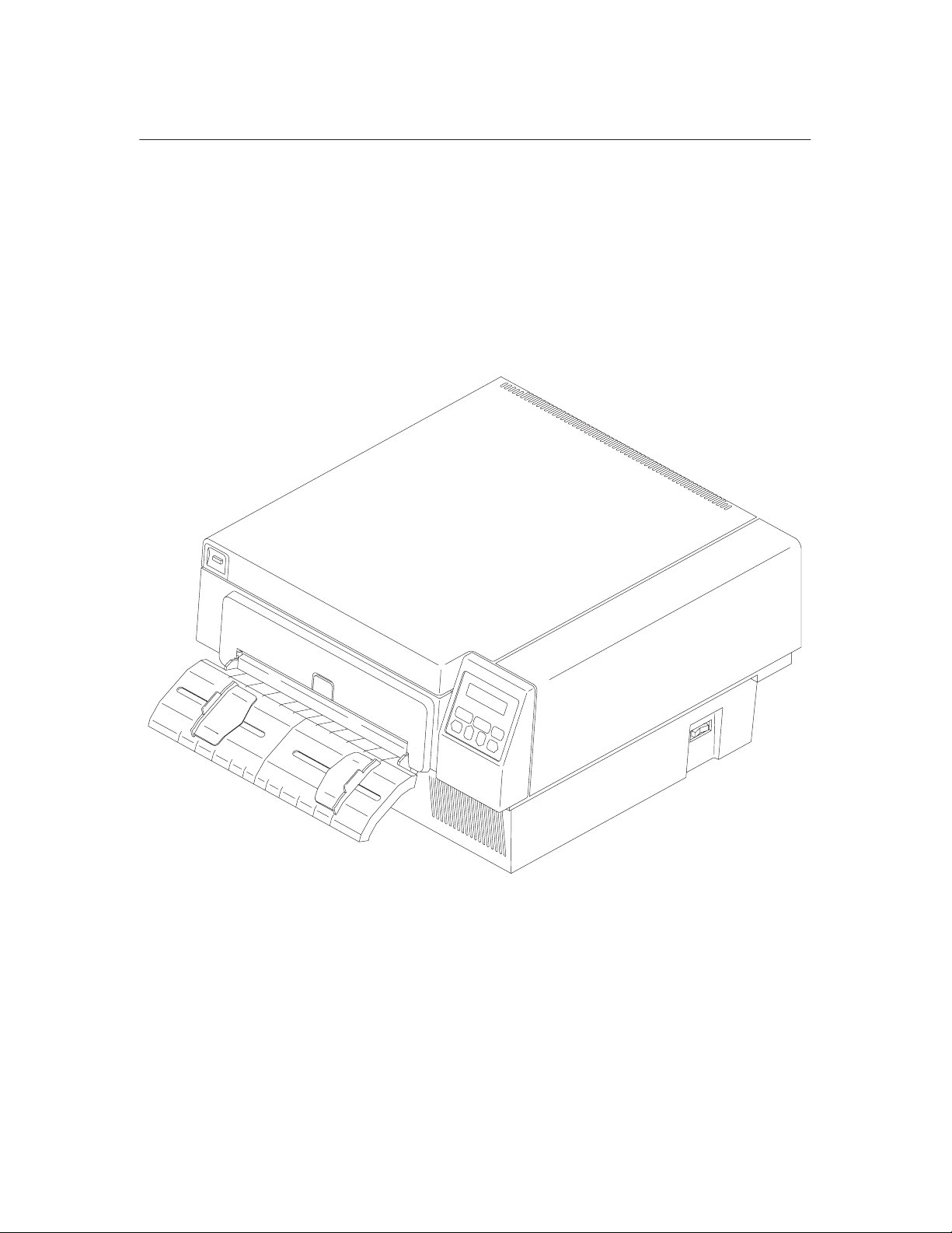
The Printer
The printer is a programmable, non–impact printer. The printing technique is a
plain paper electrophotographic process, which uses a laser diode. Printer
emulations and font software load into the printer via diskettes.
1–4
Figure 1–1. The Printer
Introduction
Page 13

Printer Features
The printer prints up to 24 pages per minute on an 8.5 x 11 inch page and
produces a 300 x 300 dots–per–inch (dpi) resolution on a continuous length
printable area. (See Appendix A for printer specifications.)
Features of the printer include:
• Continuous fanfold paper or forms handling
• Supports a wide variety of form lengths
• User–replaceable developer kit, toner kit, and organic photoconductor
(OPC) drum kit
• Two–line, 16–character alphanumeric display that provides operating and
error messages
• Diskette drive which is used to load and store preset configurations,
printer emulations and fonts from a diskette
• Second diskette drive which stores fonts (optional)
• Serial or parallel interface
• Coax or twinax interface (optional)
• Ethernet LAN interface (optional)
Introduction
1–5
Page 14

Emulations
The printer comes with HPr Laserjet PCL5r, IPDS, or the Printronix
LinePrinter Plust emulation. The LinePrinter Plus emulation includes the
following printer protocols:
• Printronix P–Series
• Printronix P–Series XQ
• Serial Matrix
• Proprinter III XL
• Epson FX–1050
LinePrinter Plus emulation provides portrait and landscape image orientation.
Automatic 1–up, 2–up, 4–up, and gray bar overprinting are also provided. The
emulation offers proportional (scalable) fonts and multi–up form definition
capability as well.
Optional emulations are also available on diskette. Refer to Appendix A for a list
of optional emulations. Refer to the Programmer’s Reference Manual or
Operator’s Guide supplied with each emulation diskette for specific information.
Hardware Options
Ask your printer representative about these options which can enhance your
printer’s versatility:
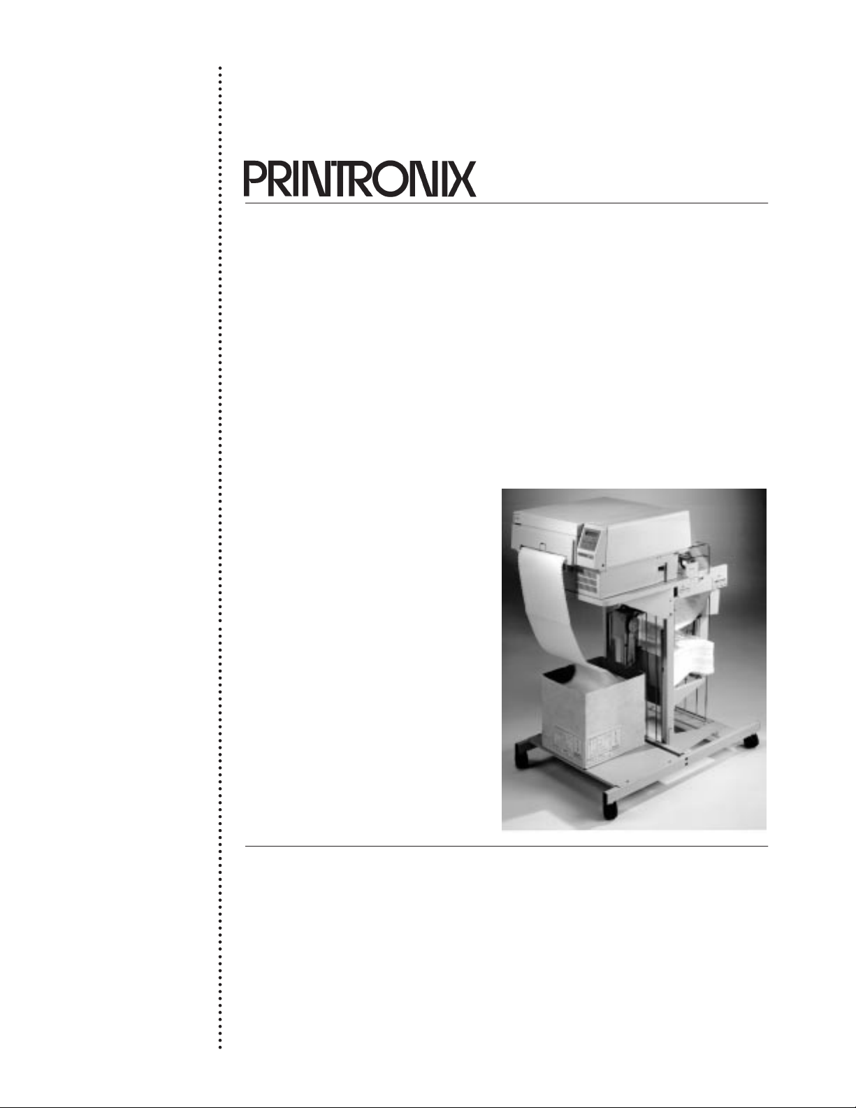
• Paper stacker with printer stand
The paper stacker provides for properly stacked paper from the beginning to
completion of the print job. The stacker will hold an entire box of media.
• Memory expansion (4 meg and 16 meg increments)
The L1024 has 8 meg of memory factory installed. Memory expansion modules
are available in increments of either 4 or 16 meg. Using these modules, printer
memory can be expanded to 40 meg.
• Second Floppy Disk Drive
A second floppy disk drive can be installed, as disk drive B.
1–6
Introduction
Page 15

• LAN connection
A hardware option is available for proper connection of the printer to a LAN.
• Coax/Twinax connection
A hardware option is available for proper connection of the printer for
Coax/Twinax operation.
• Optional fonts
Optional printer fonts can be purchased and loaded into the printer using a
diskette.
Fonts and Forms
The printer provides a variety of resident fonts. The available fonts are dependent
the emulation used. For example, the Printronix LinePrinter Plus emulation
provides Letter Gothic, Courier, OCR–A, and OCR–B as standard fonts sets.
Additional fonts can be loaded from the host computer or from optional font
diskettes into printer memory. Once loaded, these additional fonts are accessed in
the same way as the resident fonts. Printer languages that support downloaded
fonts will not retain these fonts in memory when the printer is powered off.
Forms may be stored together with fonts. The storage space for forms and fonts
depends on memory availability and diskette space. Different fonts and forms
may be used depending on the emulation installed.
Introduction
1–7
Page 16

General Laser Printer Technology
The operation of a laser printer is somewhat different than that of an impact
printer. They produce an entire page at once, compared to line printers, which
produce complete character lines.
NOTE: If the software application fails to give a form feed at the end of the
data, and the data does not exceed the selected lines per page
setting, the page will not print. Rather, it will remain in memory.
The laser printer has two basic functional parts: the engine and the controller.
The engine is responsible for the mechanical aspects of producing the page. The
controller controls the printer and is responsible for electronic data
manipulations.
NOTE: Laser printers can not print to the physical edge of the paper. If the
document image runs to the edge of the paper, portions of the image
may be lost.
The electrophotographic printing process, shown in Figure 1–2, consists of the
following steps:
1. Charging: The charge corona is a thin wire electrode that extends
across the width of the media. This electrode places a high–voltage
electrostatic charge on the organic photoconductor (OPC) drum.
2. Imaging: Based on data received from the host computer, a bit–mapped
image of the page is generated in random access memory (RAM) on the
controller (not shown).
3. Exposing: The laser scanning unit (LSU) exposes areas of the OPC
which are to be imaged (i.e., black). This forms a latent image of the
bit–mapped data. This image is made up of charged and uncharged
areas.
4. Developing: The latent image areas of the OPC attract toner from the
developer unit to form the developed image on the OPC drum. Since the
charged areas of the drum have the same charge as the toner, they repel
the toner.
1–8
Introduction
Page 17
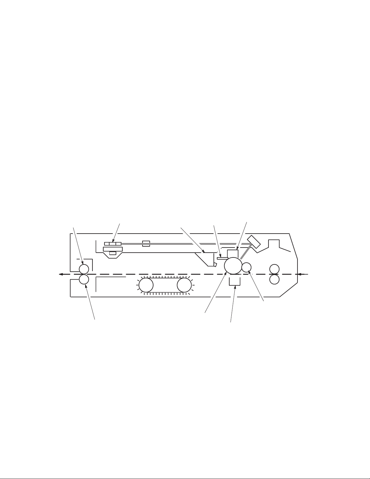
5. Transferring: Another thin wire electrode, the transfer corona, puts a
high electrostatic charge on the paper. This charge attracts the toner,
transferring the toner from the OPC drum to the paper.
6. Fusing: Heat and pressure rollers fuse the transferred image to the
paper.
7. Cleaning: As the OPC drum continues to turn, erase lamps remove all
residual electrostatic charge from the OPC. The cleaning unit then
removes unused toner from the OPC.
Paper
Exit
Heat
Roller
Pressure
Roller
Laser
Scanning
Unit
Erase
Lamps
Cleaning
Unit
OPC
.
Transfer
Corona
.
Charge
Corona
Paper
Entry
Developer
Unit
Introduction
Figure 1–2. The Printing Process
1–9
Page 18

1–10
Introduction
Page 19

2
Chapter Contents
Setting Up the Printer
Safety Precautions 2–2. . . . . . . . . . . . . . . . . . . . . . . . . . . . . . . . . . . . . . . . . . . . . . . .
Check the Power Requirements 2–3. . . . . . . . . . . . . . . . . . . . . . . . . . . . . . . . . . . . . .
Select a Site 2–4. . . . . . . . . . . . . . . . . . . . . . . . . . . . . . . . . . . . . . . . . . . . . . . . . . . . .
Unpack the Printer 2–6. . . . . . . . . . . . . . . . . . . . . . . . . . . . . . . . . . . . . . . . . . . . . . . .
Initial Setup 2–7. . . . . . . . . . . . . . . . . . . . . . . . . . . . . . . . . . . . . . . . . . . . . . . . . . . . .
Install the Developer Unit 2–10. . . . . . . . . . . . . . . . . . . . . . . . . . . . . . . . . . . . . .
Add the Starter Toner 2–11. . . . . . . . . . . . . . . . . . . . . . . . . . . . . . . . . . . . . . . . .
Install the Ozone Filter 2–13. . . . . . . . . . . . . . . . . . . . . . . . . . . . . . . . . . . . . . . .
Install the Waste Toner Container 2–14. . . . . . . . . . . . . . . . . . . . . . . . . . . . . . . .
Install the Fuser Cleaner Felt 2–16. . . . . . . . . . . . . . . . . . . . . . . . . . . . . . . . . . . .
Install the OPC Drum Unit 2–17. . . . . . . . . . . . . . . . . . . . . . . . . . . . . . . . . . . . .
Load Paper 2–18. . . . . . . . . . . . . . . . . . . . . . . . . . . . . . . . . . . . . . . . . . . . . . . . . .
Install the Emulation Boot Diskette 2–20. . . . . . . . . . . . . . . . . . . . . . . . . . . . . .
Cable Connections 2–21. . . . . . . . . . . . . . . . . . . . . . . . . . . . . . . . . . . . . . . . . . . . . . .
Check for Interference 2–23. . . . . . . . . . . . . . . . . . . . . . . . . . . . . . . . . . . . . . . . . . . .
Transporting the Printer 2–24. . . . . . . . . . . . . . . . . . . . . . . . . . . . . . . . . . . . . . . . . .
Short Distance Transport 2–24. . . . . . . . . . . . . . . . . . . . . . . . . . . . . . . . . . . . . . .
Long Distance Transport 2–25. . . . . . . . . . . . . . . . . . . . . . . . . . . . . . . . . . . . . . .
2–1Setting Up the Printer
Page 20

Safety Precautions
The use of controls or adjustments or the performance of procedures
other than those specified in this manual may result in exposure to
hazardous radiation.
Die Nichtbeachtung der in diesem Handbuch dargelegten Punkte sowie
die Verwendung anderer Kontroll– oder Steuereinrichtungen kann dazu
führen, daß gefährliche Strahlung abgegeben wird.
L’utilisation de commandes et réglages ou l’exécution de procédures
autres que celles spécifiées dans ce manuel peuvent entraîner une
exposition à des radiations dangereuses.
WARNING
WARNUNG
ATTENTION
Be aware of components in the printer that are potentially hazardous or easily
damaged. For example, the fuser unit becomes very hot under normal operating
conditions, and several components use high voltage.
Observe the following precautions to ensure personal safety and proper
installation and operation of the printer.
• Read all instructions.
• Save these instructions for later reference and use.
• Follow all warnings and instructions printed in this manual and marked
on the printer.
• Keep combustible materials away from the printer.
• Provide adequate ventilation.
• Never push objects of any kind through the cabinet slots. They may
contact dangerous voltage points or other hazards. Injury to the operator,
damage to the printer, or fire could result.
• Never spill liquid of any kind on or in the printer. Use only cleaning
agents and methods indicated in this manual.
2–2 Setting Up the Printer
Page 21

• Make sure nothing rests on the power cord. Do not locate the power cord
where people will walk on it. Do not place the power cord under any
carpet.
• Do not lean or place heavy objects on top of the printer.
For additional requirements, refer to Appendix A.
Check the Power Requirements
WARNING
Do not connect the printer to the power source until instructed to do so
and until all shipping restraints have been removed.
WARNUNG
Den Drucker nur unter Anleitung an die Stromquelle anschließen, und
erst dann, wenn alle Versandmaterialien entfernt worden sind.
ATTENTION
A moins d’en avoir recu l’ordre, ne pas brancher l’imprimante avant
d’en avoir ôté tout le matériel d’emballage.
The printer must be connected to an acceptable AC power source; otherwise, the
printer will not operate properly and may be damaged. The rear side panel label
identifies the correct power source for the printer: either 100 to 120 VAC, 60 Hz
or 220 to 240 VAC, 50 Hz.
The power source must be properly grounded. Since large power fluctuations can
cause the printer to malfunction, it should be connected to a “noise–free” power
source, not subject to surges or noise generated by motors, lighting, or air
conditioning equipment on the same circuit. To allow for an adequate power
cable run, the printer should be placed no more than eight feet (2.5 meters) from
the power outlet.
2–3Setting Up the Printer
Page 22

Select a Site
When selecting the location for the printer, consider the following power
requirements, interface requirements, and environmental factors:
• A proper power source must be available. (Complete power requirements
are specified in the “Check Power Requirements” section on page 2–3.)
• The location must be within the maximum cable length specifications for
the host computer interface.
• The temperature range should be +50°F to +90°F, with no sudden
changes in temperature or humidity. The printer should be positioned
away from any air drafts from heating or air conditioning ducts.
• Insure that the room provides adequate ventilation. The minimum room
volume is 1000 cubic feet and must provide, at a minimum, one fresh air
exchange every two hours.
• The location should provide enough space for maintenance and
replacement of consumables (toner, developer, paper, etc.). Refer to
Figure 2–1.
• The printer should not be exposed to direct sunlight or hot lighting
equipment. This may cause an abnormal temperature rise in the printer
and adversely affect its operation. If necessary, shade or screen the
printer from such exposure.
• Avoid exposing the printer to any corrosive gases or vapors.
• Avoid installing the printer in an area subject to heavy vibrations.
For additional environmental requirements, refer to the Introduction chapter and
to Appendix A.
Figure 2–1 illustrates spatial site requirements for the printer. The dimensions are
listed in inches and include the requirements with the top and front covers open.
NOTE: The actual printer dimensions are shown in Figure 2–1. When
installing the printer at your site, allow an additional 6 inches
clearance behind the printer for connection of interface and power
cables.
2–4 Setting Up the Printer
Page 23
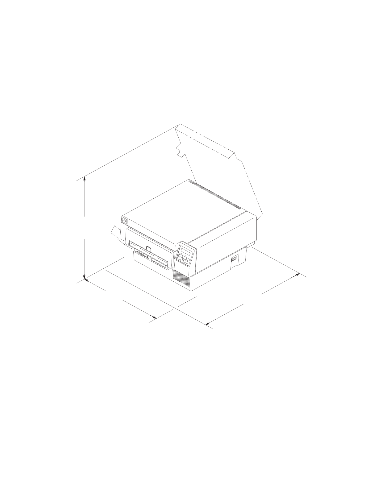
23 inches
19 inches
25 inches
Figure 2–1. Clearance Requirements
2–5Setting Up the Printer
Page 24
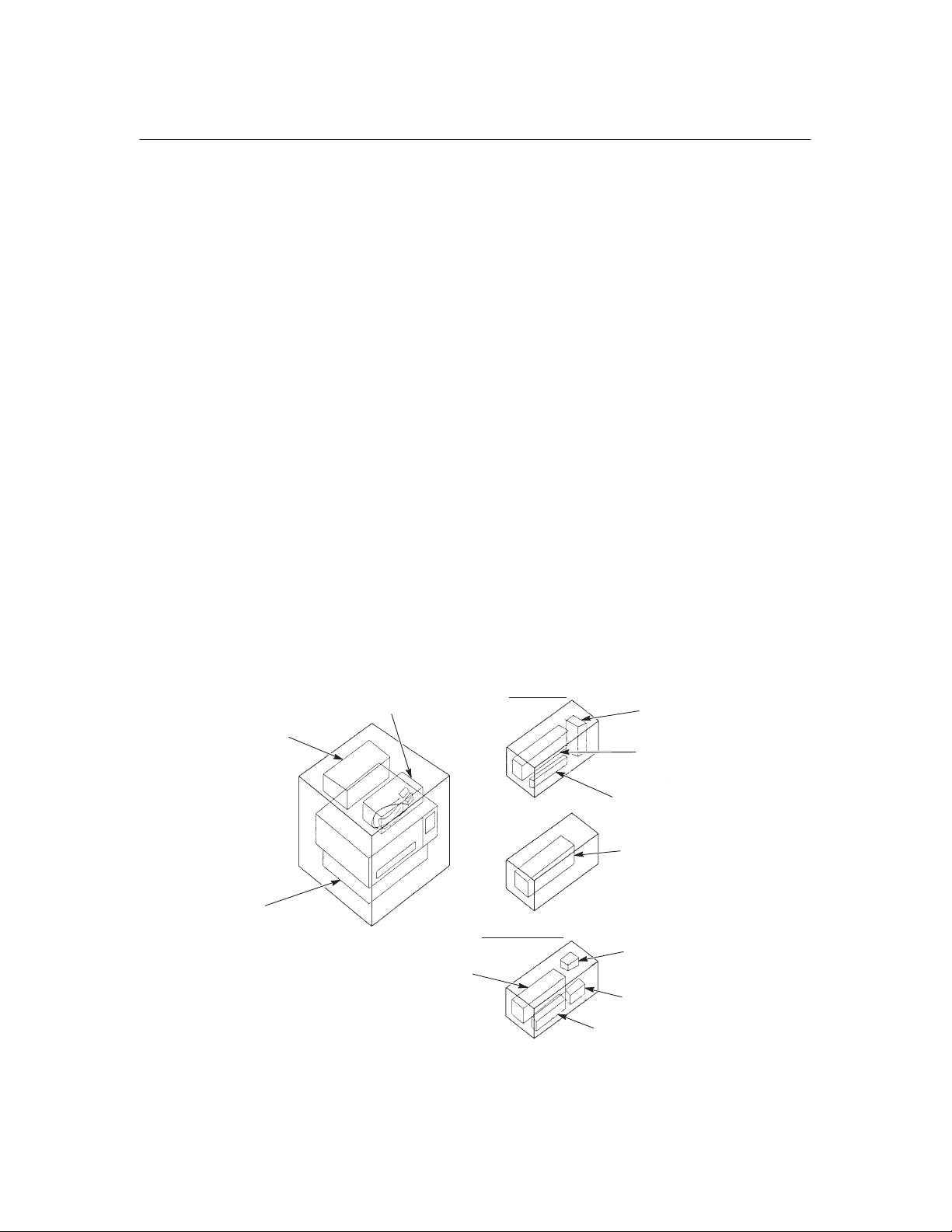
Unpack the Printer
The printer is shipped in two cartons. The carton containing the consumables
ship set is placed on top of the printer carton. The printer carton is shown in
Figure 2–2 with all of the contents. The consumables ship set; which is made up
of the toner kit, OPC cartridge, and developer kit, is shipped in its own carton
(not shown in Figure 2–2), as shown in the figure below.
NOTE: Save the printer shipping materials in case they are needed to
transport the printer to a new location.
NOTE: The material in the toner kit is recyclable. Save the toner box and
packaging materials for recycling. A recycling shipping label, with
instructions attached, is provided.
The OPC unit must be kept in its protective bag whenever the unit is not
housed in the printer.
CAUTION
Carefully open each carton and examine contents for indication of damage during
transport. Use care when lifting the printer from the shipping carton.
Emulation Diskettes,
Documentation, etc.
Printer
Power Cable and
Front Paper Guide
Developer Unit
Toner Kit:
Developer kit:
W
aste Container (2)
T
oner Bottle (2)
Cleaner Felt (2)
OPC Unit
Ozone Filter
Cleaning Kit
Starter T
oner
Figure 2–2. Unpacking the Printer
2–6 Setting Up the Printer
Page 25

Initial Setup
To prepare the printer for operation, install the consumables that are packaged in
consumable kits within the consumable ship set box. They are:
• Developer unit (Developer Kit)
• Starter Toner (Developer Kit)
• Ozone filter (Developer Kit)
• Waste toner container (Toner Kit)
• Fuser cleaner felt (Toner Kit)
• OPC drum unit
NOTE: The material in the toner kit is recyclable. Save the toner box and
To install the consumables, perform the following procedures in the order
presented.
packaging materials for recycling. A recycling shipping label is
provided with instructions attached.
2–7Setting Up the Printer
Page 26
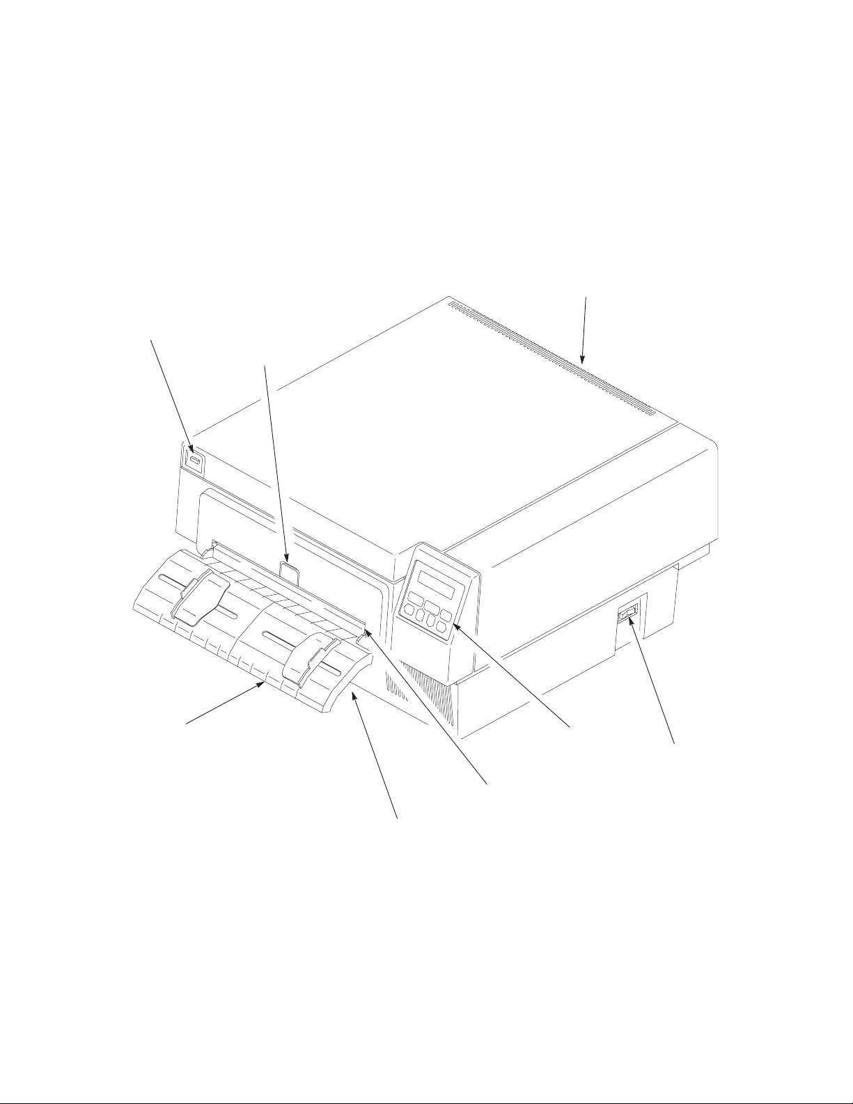
Exit Paper Guide
(not shown)
Top Cover Latch
Paper Tension
Release
Input Paper Guide
Paper Entry
Disk Drive(s)
(not shown under
paper guide)
Control Panel
Power Switch
Figure 2–3. Front and Right Side View of Printer
2–8 Setting Up the Printer
Page 27
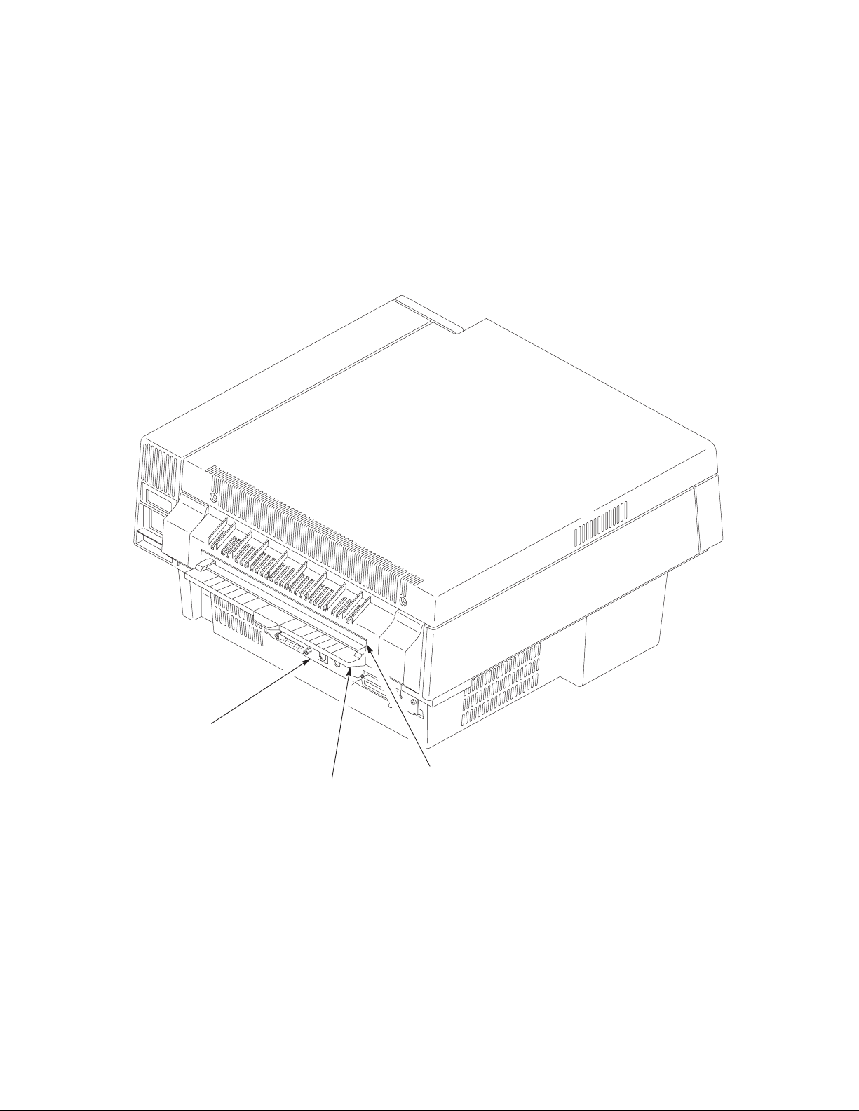
I/O Panel
Paper Exit
Exit Paper Guide
Figure 2–4. Rear and Left Side View of Printer
2–9Setting Up the Printer
Page 28

Install the Developer Unit
Perform this procedure only if this is the initial installation and no toner
has been added to the developing unit. Otherwise, fill the toner hopper
with toner from the toner bottle.
Refer to Figure 2–5 and perform the following steps:
1. Raise the top of the printer by firmly pressing the button on the left of
the front panel.
2. Remove the new developer unit from its foil package.
3. Slide the developer unit along the plastic rails on either side of the printer
until the developer unit is in position.
4. Lock the developer unit in place by pushing the two green lock–down
clamps down until they click.
CAUTION
Lock–down Clamps
Developer Unit
Figure 2–5. Installing the Developer Unit
2–10 Setting Up the Printer
Page 29

Add the Starter Toner
For the initial installation, use the starter toner bottle from the
developer kit. Do not use the toner bottles in the toner kit, which consists
of two toner bottles, two fuser cleaner felts, and two waste toner
containers.
After adding the starter toner, do not add toner from the toner kit until
the printer displays a toner low message. Starter toner will provide
approximately 200 pages of print at 5%.
Toner is light and easily becomes air–borne and can contaminate the printer. Be
careful not to stain your hands, clothes, or the interior of the printer with toner.
NOTE: If toner is spilled, use a toner vacuum to clean up the loose toner.
Do not use water to clean the toner from the printer. Any toner
remaining on clothes can be removed with a cloth dampened in cold
water. Never use hot water to remove toner from clothes or skin.
Use care when handling toner.
IMPORTANT
When the toner is low, the printer will stop and the LCD will show “03 ADD
TONER AND CHK WASTE BOTTLE.”
NOTE: Do not turn off the printer during a print job to add toner; otherwise,
all unprinted data will be lost. Once the toner is added, press ON
LINE to continue printing.
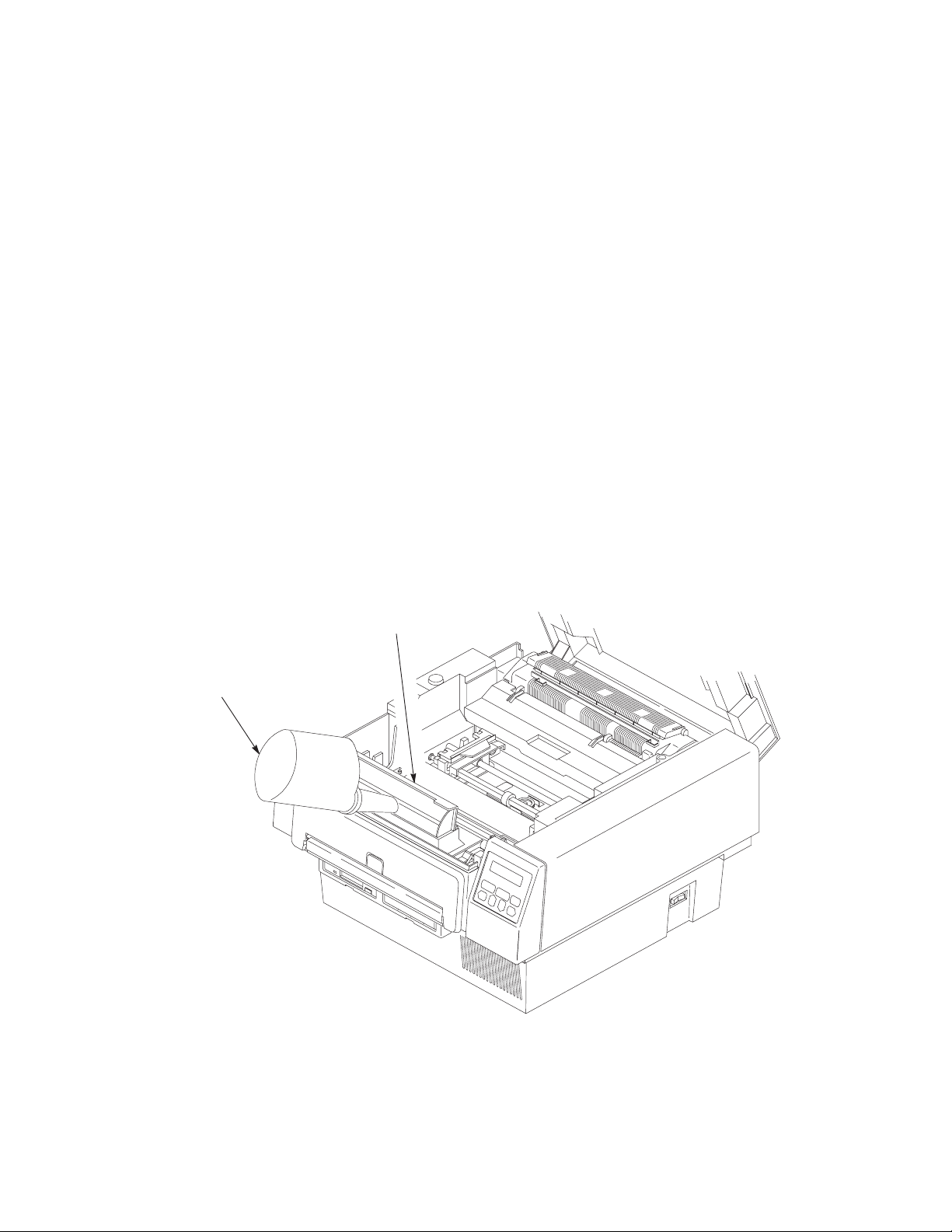
Refer to Figure 2–6 and perform these steps:
1. Open the starter toner bottle from the developer kit, and attach the
spout.
2. Carefully open the developer unit cover.
3. Carefully pour the starter toner into the developer unit. Make sure to
spread the toner evenly from side to side.
2–11Setting Up the Printer
Page 30
IMPORTANT
Do not squeeze the toner bottle as you pour the toner. Doing so could
cause the loose toner to be blown out of the hopper and contaminate the
printer and soil hands and clothes.
If the toner bottle does not empty completely, gently tap the end of the
bottle while holding it over the hopper.
4. Close the developer unit cover. Press the cover until you hear a “click”
which indicates that the developer unit is closed completely.
5. Clean up any toner that may have spilled during this process using one
of the moist towels that come with the cleaning kit inside the developer
kit.
NOTE: Some software stops communicating with the printer if the printer is
off line for more than two minutes. In this case, you may need to
restart your print job.
Starter Toner Bottle
(with spout attached)
Developer Unit Cover
(shown in the open position)
Figure 2–6. Filling the Toner Cartridge
2–12 Setting Up the Printer
Page 31

Install the Ozone Filter
Refer to Figure 2–7 and perform the following steps:
1. Remove the ozone filter from the plastic bag.
2. Holding the ozone filter by its tab, place the ozone filter into the slot on
the inside of the front of the printer.
Figure 2–7. Installing the Ozone Filter
Ozone Filter
2–13Setting Up the Printer
Page 32

Install the Waste Toner Container
NOTE: The OPC drum unit must be removed before placing the waste toner
container into its opening.
Refer to Figure 2–8 and perform these steps:
The OPC drum unit is light sensitive. Install it within five minutes.
When removing the drum unit from the foil bag, do not touch the
surface of the drum unit. Fingerprints and scratches can damage the
drum surface and cause poor print quality. Do not rotate the drum unit
manually. Forced rotation will cause an incorrect count for the life of the
drum unit and may cause poor print quality.
1. If installed, remove the OPC unit by lifting it carefully out of the printer
and place it on a flat surface.
2. Remove one of the waste toner containers from the toner kit box.
CAUTION
NOTE: If the green cap is placed on the filling hole, it cannot be removed,
in which case the waste toner container should be discarded.
3. Make sure that the green cap is on the cap holder rather than on the
filling hole of the new waste toner container.
NOTE: The waste toner container must be properly seated in the printer or
the printer will display an error message when the printer cover is
closed.
4. Install the waste toner container in the printer as shown in Figure 2–8.
2–14 Setting Up the Printer
Page 33

Waste Toner
Container
Figure 2–8. Installing the Waste Toner Cartridge
2–15Setting Up the Printer
Page 34

Install the Fuser Cleaner Felt
Refer to Figure 2–9 and perform these steps:
1. Remove one of the fuser cleaner felts from the toner kit box
2. Remove the fuser cleaner felt from its plastic wrapping.
3. Lift the cleaner felt cover on the fuser unit. If the cleaner felt cover
comes off, simply slide the shafts into the appropriate openings in the
fuser unit.
4. Carefully slide the fuser cleaner felt into the opening on the top of the
fuser unit.
5. Close the cleaner felt cover.
Fuser Cleaner Felt
Fuser Cleaner
Felt Cover (shown
in the open position)
Figure 2–9. Installing the Fuser Cleaner Unit
2–16 Setting Up the Printer
Page 35

Install the OPC Drum Unit
The OPC drum unit is light sensitive. Install it within five minutes.
When removing the drum unit from the foil bag, do not touch the
surface of the drum unit. Fingerprints and scratches can damage the
drum surface and cause poor print quality. Do not rotate the drum unit
manually. Forced rotation will cause an incorrect count for the life of the
drum unit and may cause poor print quality.
Refer to Figure 2–10 and perform these steps:
1. Remove the OPC drum unit from its foil bag.
NOTE: Save the foil bag and insert the OPC drum unit into the bag
whenever the printer cover is open for more than five minutes.
2. Insert the drum unit behind the developer unit. The OPC drum unit will
slide into place easily.
CAUTION
NOTE: The drum unit does not lock into place; it rests behind the developer
unit.
3. Close the printer cover.
OPC Drum Unit
Figure 2–10. Installing the OPC Drum Unit
2–17Setting Up the Printer
Page 36

Load Paper
NOTE: Before loading paper, make sure the Paper Length and Paper Width
Refer to Figure 2–11 and perform the following steps:
1. Raise the top of the printer by firmly pressing the top cover latch on the
2. Insert paper into the front of the printer. Press the tension release as
3. Open the tractor gates on the tractor unit, place the paper on the pins,
4. Unlock the tractors by pushing up the tractor locks.
5. Adjust the width of the tractors so that the paper is tight.
options are set properly in the Paper Control configuration menu.
Refer to the Configuring the Printer chapter, page 3–17, for details.
left side of the front panel.
required to insert the paper.
and close the tractor gates.
6. Lock the tractor unit by pushing down on the tractor locks.
7. To ensure that the printer will start at the top of a page, check the
following:
The leading edge of the paper should be straight; not torn, crooked, or curled.
The leading edge of the paper should not extend beyond the tractors. This allows
the printer to set the top of form accurately and automatically at the leading edge
of the paper.
8. Close the top cover of the printer.
NOTE: Repeat the paper loading procedure whenever top of form must be
reset (e.g., after clearing a paper jam, loading new paper, etc.). For
details on clearing paper jams, refer to the Diagnostics and
Troubleshooting chapter.
2–18 Setting Up the Printer
Page 37

Top Cover Latch
Tension Release
Tractor Gate
Paper Entrance
Tractor Pins
Tractor Locks
Figure 2–11. Loading Paper
2–19Setting Up the Printer
Page 38

Install the Emulation Boot Diskette
Diskette Drive “A”
Eject Button
Write
Protection
Tab
Figure 2–12. Installing the Diskette
1. Make sure the power switch on the printer is turned off.
CAUTION
Do not bend or touch exposed areas of the diskette. Keep the diskette
away from magnetic fields. Do not store in especially cold (50
(120
° F) areas.
° F) or hot
2. Remove the emulation boot diskette from its shipping container. Contact
your vendor if the diskette is missing.
3. Make sure the diskette is not write–protected. The tab must be closed.
4. Insert the emulation boot diskette into drive A until it snaps into place.
5. If you are installing a font diskette, insert the diskette into drive B.
Make sure this diskette is not write–protected. (The tab must be closed
as shown in Figure 2–12.)
NOTE: The printer comes standard with one floppy disk drive. Certain
optional software emulations, require two floppy disk drives. For
software emulations requiring two floppy disks, insert the program
disk into the Drive A and the fonts disk into Drive B.
2–20 Setting Up the Printer
Page 39

Cable Connections
Now the printer can be connected to power and to your system. To connect the
cables, refer to Figure 2–13 and perform the steps listed below.
To prevent injury to yourself or damage to the printer, make sure the
printer is connected to a proper power source.
Um Personenschäden oder eine Beschädigung des Druckers zu
verhindern, sicherstellen, daß der Drucker an eine geeignete
Stromquelle angeschlossen ist.
S’assurer que l’imprimante est branchée afin d’éviter tout risque de
blessures corporelles ou de dommages à l’imprimante.
1. Verify that the site line voltage is the same as the voltage specified in
“Check the Power Requirements” section, page 2–3.
WARNING
WARNUNG
ATTENTION
2. Make sure the printer power switch is set to 0 (OFF).
3. Connect the power cord (supplied with the printer) to the AC power
connector on the printer.
NOTE: To avoid possible electrical interference, separate the AC power
cord and the interface cable.
4. Connect the opposite end of the power cord to the AC line receptacle.
5. Connect the interface cable to the appropriate printer interface connector
and to the host computer. The printer supports a variety of standard and
optional interfaces:
• Centronics parallel
• Dataproducts parallel (requires optional cable adapter)
• RS–232 and RS–422 serial
• Coax/Twinax (option)
• Local Area Network (option)
2–21Setting Up the Printer
Page 40

NOTE: RS–422 can be enabled or disabled via a menu option on the control
panel under the host interface selection. Make sure this selection is
properly made for your application.
NOTE: The printer must be properly configured for the appropriate
interface. Refer to the Configuring the Printer chapter for more
information.
AC Plug
RS–232/422 Port
Coax/Twinax Connector
Diagnostic Test Port
Centronics Parallel Port or
Dataproducts Port (with adapter)
Figure 2–13. Cable Connections
2–22 Setting Up the Printer
Page 41

Check for Interference
The printer should be used only with FCC, VDE, or CE certified computing
devices. If the printer is installed within 10 feet of audio or video equipment,
interference may occur. Determine if there is interference by turning the printer
ON and OFF and checking the audio and video equipment for noise spikes. If
interference occurs, perform the following:
1. Relocate the printer or the electronic device affected by the interference,
including the antenna, if applicable.
2. Ensure that the printer and electronic device are on separate power
circuits or install AC line filters.
3. Ensure that the wall outlets are properly grounded.
If these steps do not resolve the problem, refer to the Federal Communications
Commission Booklet, “How to Identify and Resolve Radio – TV Interference
Problems” (stock number: 004–000–00345–4), available through the U.S.
Government Printing Office, Washington, D.C. 20402.
2–23Setting Up the Printer
Page 42

Transporting the Printer
Take precautions to prevent damage to the printer during transport. If a move
requires trucking, use the original packaging materials.
Short Distance Transport
1. Turn off the printer and unplug the power cord from the wall outlet.
2. Remove the paper.
3. Remove all external communication and interconnection cables (AC
line cord, coax cable, any optional attachment cards, etc.) from the
printer.
4. Before you remove the developer unit, place several sheets of paper in
front of the printer and on a work surface that you will set the developer
on. Do this in case any toner spills.
5. Remove the developer unit. (It is a good idea to have a toner vacuum
handy when performing this step.)
6. Place the developer unit in a sealable plastic bag.
7. Temporarily remove the OPC drum in order to remove the waste toner
container.
NOTE: The waste toner container is recyclable. A recycling shipping label
is provided, with instructions attached, in the toner box.
8. Place the green cap on the filler hole of the waste toner container and
remove it from the printer and package it for recycling.
9. Install the OPC Drum in the printer.
CAUTION
Do not touch exposed areas of or bend the diskette. Keep the diskette
away from magnetic fields. Do not store in especially cold (50
(120
°F) areas.
10. Remove the diskette from the disk drive and place it in a protective
cover.
°F) or hot
11. Always carry the printer and developer unit upright.
2–24 Setting Up the Printer
Page 43

Long Distance Transport
1. Pack all connecting cables in a plastic bag.
2. Place the developer unit in appropriate packaging for recycling. It is not
practical to move the developer unit over long distances.
3. Using a towel and a toner vacuum, remove residual toner from inside
the printer.
Failure to secure the pressure roller for shipment can cause permanent
damage to the printer.
The fuser must be cool before proceeding further.
4. Secure the fuser pressure roller (lower roller) to prevent it from
bouncing during shipment. Insert the original foam pad between the
fuser rollers.
CAUTION
NOTE: If the original foam pad is not available for use, use bubble wrap or
other foam packing material to secure the lower fuser roller.
NOTE: Replacement packaging material can be procured from your
authorized representative.
5. Use original packing material if available. Otherwise, use sufficient
shock–absorbing packaging material.
6. Secure the top and front covers to keep them from opening.
7. At the new site, install a new developer unit and waste toner container.
2–25Setting Up the Printer
Page 44

2–26 Setting Up the Printer
Page 45

3
Chapter Contents
Configuring the Printer
Overview 3–4. . . . . . . . . . . . . . . . . . . . . . . . . . . . . . . . . . . . . . . . . . . . . . . . . . . . . . .
Changing Printer Settings 3–5. . . . . . . . . . . . . . . . . . . . . . . . . . . . . . . . . . . . . . . . . .
Saving a Configuration 3–7. . . . . . . . . . . . . . . . . . . . . . . . . . . . . . . . . . . . . . . . . . . .
Modifying a Configuration 3–10. . . . . . . . . . . . . . . . . . . . . . . . . . . . . . . . . . . . . . . .
Printing a Configuration 3–13. . . . . . . . . . . . . . . . . . . . . . . . . . . . . . . . . . . . . . . . . . .
Factory Settings 3–14. . . . . . . . . . . . . . . . . . . . . . . . . . . . . . . . . . . . . . . . . . . . . . . . .
Configuration Menus 3–16. . . . . . . . . . . . . . . . . . . . . . . . . . . . . . . . . . . . . . . . . . . . .
Paper Control Menu 3–17. . . . . . . . . . . . . . . . . . . . . . . . . . . . . . . . . . . . . . . . . . . . . .
Image Width 3–18. . . . . . . . . . . . . . . . . . . . . . . . . . . . . . . . . . . . . . . . . . . . . . . .
Paper Length 3–18. . . . . . . . . . . . . . . . . . . . . . . . . . . . . . . . . . . . . . . . . . . . . . . .
Horiz. Image Shift 3–18. . . . . . . . . . . . . . . . . . . . . . . . . . . . . . . . . . . . . . . . . . . .
Vert. Image Shift 3–18. . . . . . . . . . . . . . . . . . . . . . . . . . . . . . . . . . . . . . . . . . . . .
Reprint on Fault 3–18. . . . . . . . . . . . . . . . . . . . . . . . . . . . . . . . . . . . . . . . . . . . . .
Printer Control Menu 3–19. . . . . . . . . . . . . . . . . . . . . . . . . . . . . . . . . . . . . . . . . . . . .
Fuser Temperature 3–20. . . . . . . . . . . . . . . . . . . . . . . . . . . . . . . . . . . . . . . . . . . .
Energy Timeout 3–20. . . . . . . . . . . . . . . . . . . . . . . . . . . . . . . . . . . . . . . . . . . . . .
Diagnostics Menu 3–21. . . . . . . . . . . . . . . . . . . . . . . . . . . . . . . . . . . . . . . . . . . . . . . .
3–1Configuring the Printer
Page 46

Test Print 3–22. . . . . . . . . . . . . . . . . . . . . . . . . . . . . . . . . . . . . . . . . . . . . . . . . . .
Engine Life Data 3–22. . . . . . . . . . . . . . . . . . . . . . . . . . . . . . . . . . . . . . . . . . . . .
Disk Management Menu 3–23. . . . . . . . . . . . . . . . . . . . . . . . . . . . . . . . . . . . . . . . . .
Load Configuration 3–24. . . . . . . . . . . . . . . . . . . . . . . . . . . . . . . . . . . . . . . . . . .
Save Configuration 3–24. . . . . . . . . . . . . . . . . . . . . . . . . . . . . . . . . . . . . . . . . . .
Print Configuration 3–24. . . . . . . . . . . . . . . . . . . . . . . . . . . . . . . . . . . . . . . . . . .
Delete Configuration 3–25. . . . . . . . . . . . . . . . . . . . . . . . . . . . . . . . . . . . . . . . . .
Power–up Configuration 3–25. . . . . . . . . . . . . . . . . . . . . . . . . . . . . . . . . . . . . . .
Protect Configurations 3–25. . . . . . . . . . . . . . . . . . . . . . . . . . . . . . . . . . . . . . . . .
Mode (Emulation) Menu 3–26. . . . . . . . . . . . . . . . . . . . . . . . . . . . . . . . . . . . . . . . . .
Impact Printer 3–27. . . . . . . . . . . . . . . . . . . . . . . . . . . . . . . . . . . . . . . . . . . . . . .
PCL5 3–27. . . . . . . . . . . . . . . . . . . . . . . . . . . . . . . . . . . . . . . . . . . . . . . . . . . . . .
IGP/PGL 3–27. . . . . . . . . . . . . . . . . . . . . . . . . . . . . . . . . . . . . . . . . . . . . . . . . . .
IGP/VGL 3–28. . . . . . . . . . . . . . . . . . . . . . . . . . . . . . . . . . . . . . . . . . . . . . . . . . .
CTHI 3–28. . . . . . . . . . . . . . . . . . . . . . . . . . . . . . . . . . . . . . . . . . . . . . . . . . . . . .
IPDS 3–28. . . . . . . . . . . . . . . . . . . . . . . . . . . . . . . . . . . . . . . . . . . . . . . . . . . . . . .
Maintenance/Miscellaneous Menu 3–29. . . . . . . . . . . . . . . . . . . . . . . . . . . . . . . . . . .
Panel Key Sound 3–29. . . . . . . . . . . . . . . . . . . . . . . . . . . . . . . . . . . . . . . . . . . . .
Alarm 3–29. . . . . . . . . . . . . . . . . . . . . . . . . . . . . . . . . . . . . . . . . . . . . . . . . . . . . .
Power–up State 3–29. . . . . . . . . . . . . . . . . . . . . . . . . . . . . . . . . . . . . . . . . . . . . .
Hex Dump Mode 3–30. . . . . . . . . . . . . . . . . . . . . . . . . . . . . . . . . . . . . . . . . . . . .
PTX–Setup Option 3–31. . . . . . . . . . . . . . . . . . . . . . . . . . . . . . . . . . . . . . . . . . .
Display Language 3–31. . . . . . . . . . . . . . . . . . . . . . . . . . . . . . . . . . . . . . . . . . . .
Host Interface Menu 3–32. . . . . . . . . . . . . . . . . . . . . . . . . . . . . . . . . . . . . . . . . . . . . .
3–2 Configuring the Printer
Page 47

Centronics Interface Parameters 3–33. . . . . . . . . . . . . . . . . . . . . . . . . . . . . . . . . . . .
Dataproducts Interface Parameters 3–36. . . . . . . . . . . . . . . . . . . . . . . . . . . . . . . . . .
Serial Interface Parameters 3–39. . . . . . . . . . . . . . . . . . . . . . . . . . . . . . . . . . . . . . . .
Font Memory Menu 3–44. . . . . . . . . . . . . . . . . . . . . . . . . . . . . . . . . . . . . . . . . . . . . .
Maximum Character Memory 3–45. . . . . . . . . . . . . . . . . . . . . . . . . . . . . . . . . . .
Maximum Cache Memory 3–45. . . . . . . . . . . . . . . . . . . . . . . . . . . . . . . . . . . . . .
Maximum Cache Size 3–46. . . . . . . . . . . . . . . . . . . . . . . . . . . . . . . . . . . . . . . . .
Maximum Cached Characters 3–46. . . . . . . . . . . . . . . . . . . . . . . . . . . . . . . . . . .
Maximum Fonts Loaded 3–46. . . . . . . . . . . . . . . . . . . . . . . . . . . . . . . . . . . . . . .
Font Weight 3–47. . . . . . . . . . . . . . . . . . . . . . . . . . . . . . . . . . . . . . . . . . . . . . . . .
System Information Menu 3–48. . . . . . . . . . . . . . . . . . . . . . . . . . . . . . . . . . . . . . . . .
System Memory 3–48. . . . . . . . . . . . . . . . . . . . . . . . . . . . . . . . . . . . . . . . . . . . . .
3–3Configuring the Printer
Page 48

Overview
The configuration process is matching the printer operating characteristics to
those of the host computer.
This chapter explains how to use the control panel to change individual settings
and save them as a customized configuration.
Figure 3–1 shows an overview of the configuration menu. The next pages
describe how to move within the menu, change configuration settings, and save
and print configurations. This is the menu structure for the LinePrinter Plus
emulation. (Menu options are explained beginning on page 3–16.)
Paper
Control
Page 3–17 Page 3–23
Image Width
Paper Length
Hor Image Shift
Vert Image Shift
Reprint on Fault
Mode Maint / Misc
Page 3–26 Page 3–29 Page 3–32 Page 3–44
Impact Printer Panel Key Sound
Printer
Control
Page 3–19 Page 3–21
Fuser Temperature
Energy Timeout
Alarm
Power–up State
Hex Dump Mode
PTX–SETUP Option
Display Language
Diagnostics
Test Print
Engine Life Data
Host
Interface
Centronics*
Dataproducts
Serial
Twinax*
Coax
Max Char Memory
Max Cache Memory
Max Cache Size
Max Cached Char
Max Fonts Loaded
Font Weight
Drive B Fonts
Installed Fonts
Disk
Management
Load Config.
Save Config.
Print Config.
Delete Config.
Power–up Config.
Protect Configs.
Font
Memory
System
Info.
Page 3–48
System Memory
Note:
If the T
factory
default. If T
is the default.
winax interface is supportedT
winax is not supported, Centronics
winax is the
Figure 3–1. The Configuration Menu
3–4 Configuring the Printer
Page 49

Changing Printer Settings
Changing printer settings, such as paper length, emulation, and host I/O interface,
is referred to as configuring. You configure the printer using the control panel.
1. Make sure the printer is offline. If ONLINE is lit, press ON LINE.
OFFLINE
PAPER CONTROL
2. Press NEXT or PREV to cycle through these menus:
Paper Control
Printer Control
Diagnostics
Disk Management
Mode
Maint./Misc.
Host Interface
Font Memory
System Info.
3. When the desired menu is displayed, press DOWN to access the
available options or submenus for that menu.
4. Press NEXT or PREV to scroll through the values.
5. Press ENTER to select a value. An asterisk is displayed next to the
selected value.
NOTE: The ENTER switch must be unlocked to change printer settings.
The default at power–up is the “LOCKED” state. If the ENTER
switch has been locked, you must unlock it before the printer will
accept the new parameter setting. Press UP and DOWN
simultaneously to toggle between lock and unlock. When ENTER is
unlocked, the display will momentarily flash:
ENTER SWITCH
UNLOCKED
3–5Configuring the Printer
Page 50

6. If there are more values you want to change, use the UP, DOWN, NEXT
and PREV switches to access the value and press ENTER to select it.
7. At any time, you may press UP to return to the options one level higher.
8. At any time, you may also press ON LINE to save your changes
temporarily, exit the configuration menu, and place the printer online.
9. Once you have finished selecting all of your options, you can save your
configuration for later access. Save the configuration as described on
page 3–7, if desired.
IMPORTANT
If you do not save your configuration, all of the new values will be lost
when you turn off the printer. (Refer to “Disk Management Menu” on
page 3–23.)
3–6 Configuring the Printer
Page 51

Saving a Configuration
You can save up to eight different configurations to meet unique print job
requirements.
For example:
Config. 0: Factory Default (This cannot be altered. See page 3–14.)
Config. 1: Selects RS–232 Serial Interface
Config. 2: Selects Dataproducts Parallel Interface
The configurations are saved and stored on diskette for later use. These
configurations, including the factory default, will not be affected when the printer
power is turned off. If you do not save your configuration before you turn off the
printer, the current configuration will be lost.
Selects Image Width of 4 inches
Selects Paper Length of 24 inches
Selects Image Shift of 1 inch, etc.
Selects Image Width of 8 inches
Selects Paper Length of 11 inches
Selects Image Shift of 3/20 inch, etc.
NOTE: If the “Protect Configs.” option is enabled, the new configuration
will not be saved unless the existing configuration has been deleted.
Refer to page 3–25 for details.
Follow these steps to save a new configuration:
1. Press ON LINE to take the printer offline.
OFFLINE
PAPER CONTROL
2. Press NEXT or PREV until the following is displayed:
OFFLINE
DISK MANAGEMENT
3. Press DOWN.
3–7Configuring the Printer
Page 52

4. Press NEXT or PREV until the following is displayed:
DISK MANAGEMENT
Save Config.
5. Press DOWN.
6. Press NEXT or PREV to cycle through the options (1–8).
NOTE: Configuration “0” does not appear in this list. It is the default
configuration and can not be altered.
NOTE: If the “Protect Configs.” option is not enabled, the number
configuration selected will be erased in order to write the current
configuration. Make sure the number selected is empty or no longer
required before making this selection.
7. When the desired number is displayed, press ENTER to select it.
If the configuration number has been previously saved and the “Protect
Configs.” option is enabled, the following error message is displayed
briefly:
CFG FILE EXISTS
DELETE FIRST
If the configuration number has not been previously saved or the
“Protect Configs.” option is disabled, the JOB IN PROCESS light
flashes and the following is displayed briefly:
STANDBY
. . .
The following is displayed to indicate the configuration is being saved:
Save Config.
(selected number) *
3–8 Configuring the Printer
Page 53

8. It is recommended you print the configuration and store it in a safe place
for future reference. Refer to page 3–13 for details on printing the
configuration.
NOTE: If you want to make these new configuration parameters active at
printer power–up, make sure you select this configuration as the
“power–up config” (page 3–25).
3–9Configuring the Printer
Page 54

Modifying a Configuration
You can change a saved configuration by “writing” over it. For example, you can
modify Config. 1, shown below. Suppose you want to keep all settings except the
interface type (e.g., you want to change RS–232 to Centronics). It is necessary to
load a configuration, make the desired changes, delete the current “copy” of the
configuration, and save the current machine configuration (in this example,
configuration 1 with the desired changes) as the newly modified configuration.
Config. 1: Selects RS–232 Serial Interface
Selects Image Width of 4 inches
Selects Paper Length of 24 inches
Selects Image Shift of 1 inch, etc.
1. Load the configuration to be changed (for example, Config. 1).
a. Press ON LINE to take the printer offline.
OFFLINE
PAPER CONTROL
b. Press NEXT or PREV until the following is displayed:
OFFLINE
DISK MANAGEMENT
c. Press DOWN.
d. Press NEXT or PREV until the following is displayed:
DISK MANAGEMENT
Load Config.
e. Press DOWN.
f. Press NEXT or PREV to cycle through the options (0–8).
NOTE: Configuration “0” is the factory default configuration and cannot be
altered.
3–10 Configuring the Printer
Page 55

g. When the desired number is displayed, press ENTER to make
the selection. The JOB IN PROCESS light flashes and the
following is displayed briefly:
STANDBY
. . .
The following is displayed to indicate the configuration is being
loaded:
Load Config.
(selected number) *
2. Move through the menu and change all the desired values. (In this
example, you would change the interface type value from Serial to
Centronics.)
3. Press ENTER to save each new value. An asterisk is displayed next to
the selected value.
4. Before saving the modified configuration, you must delete the original.
a. Press ON LINE to take the printer offline.
OFFLINE
PAPER CONTROL
b. Press NEXT or PREV until the following is displayed:
OFFLINE
DISK MANAGEMENT
c. Press DOWN.
d. Press NEXT or PREV until the following is displayed:
DISK MANAGEMENT
Delete Config.
3–11Configuring the Printer
Page 56

e. Press DOWN.
f. Press NEXT or PREV to cycle through the options (1–8).
When the desired number is displayed (e.g., 1), press ENTER
to select it. The JOB IN PROCESS light flashes and the
following is displayed briefly:
STANDBY
. . .
Then, the following is displayed to indicate the configuration is
being deleted:
Delete Config.
1 *
5. Save the new configuration as described on page 3–7. Make sure you
select the same number (e.g., Config. 1) when saving the modified
configuration. The new configuration replaces the existing one.
6. Print a copy of this newest configuration and store it in a safe place.
Refer to page 3–13 for details.
NOTE: If you want to make these new configuration parameters active at
printer power–up, make sure you select this configuration as the
“power–up config” (page 3–25).
3–12 Configuring the Printer
Page 57

Printing a Configuration
It is recommended that you print and store your configurations for future
reference. The printout provides a list of the parameters you set when you created
this configuration.
To print a configuration:
1. Press ON LINE to take the printer offline.
OFFLINE
PAPER CONTROL
2. Press NEXT or PREV until the following is displayed:
OFFLINE
DISK MANAGEMENT
3. Press DOWN.
4. Press NEXT or PREV until the following is displayed:
DISK MANAGEMENT
Print Config.
5. Press DOWN.
6. Press NEXT or PREV to cycle through the following printout options:
Current
Factory (this is 0)
Power–up
All
1–8 customized configurations
7. When the desired option is displayed, press ENTER. The JOB IN
PROCESS light flashes and the printer prints the specified configuration.
3–13Configuring the Printer
Page 58

Factory Settings
Table 3–1 lists the the factory default settings (i.e., Config. 0). These values are
available for loading at any time, and are maintained in the printer until a new
configuration is loaded.
Paper Control
Image Width
Paper Length
Hor Image Shift
Vert Image Shift
Reprint on Fault
Table 3–1. Factory Settings
8.2 inches
1
1.0 inches
3/20 inches
0/100 inches
Enabled
Mode
Impact Printer
PCL5 (optional)
IGP/PGL (optional)
IGP/VGL (optional)
CTHI (optional)
IPDS (optional)
Maint / Misc
Panel Key Sound
Alarm
Power–up State
Hex Dump Mode
PTX_SETUP Option
SETUP PARSE
SETUP SFCC
Display Language
Host Interface
Centronics
Data Bit 8
Paper Inst Line
Data Polarity
Strobe Polarity
Output Polarity
Paper Instruction Polarity
Strobe Filter
Fast Busy
Trailing Edge
Impact Printer
(Refer to the Impact Printer
User’s Manual for defaults.)
On
On
Online
Disable
Enable
21h
English
Twinax or Centronics
Enable
Disable
Standard
Standard
Standard
Standard
Enable
Enable
Enable
3–14 Configuring the Printer
Page 59

Dataproducts
Data Bit 8
Paper Instruction Line
Data Polarity
Strobe Polarity
Output Polarity
Paper Instruction Polarity
Strobe Filter
Trailing Edge
Serial
Host Protocol
Baud Rate
Data Bits
Stop Bits
Parity
DTR Function
RTS Function
DTR Polarity
RTS Polarity
Buffer Size
Number of Buffers
FIFO Trigger
Diagnostic
Series 1 Poll
Series 1 Delay
Series 1 Idle
RS–422 Input
Enable
Disable
Standard
Standard
Standard
Standard
Enable
Enable
None
9600 baud
8 bits
1 bit
None
On/Offline and Buffer
On/Offline and Buffer
Normal
Normal
8192 bytes
2 buffers
14 bytes
None
0
0+ Msec
Disable
Disable
Font Memory
Maximum Character Memory
Maximum Cache Memory
Maximum Cache Size
Maximum Cached Characters
Maximum Fonts Loaded
Font Weight
Standard Characters
Bold Characters
Extra Bold Characters
300 KBytes
200 KBytes
900 characters
1 KBytes
5 fonts
168
218
259
3–15Configuring the Printer
Page 60

Configuration Menus
The printer provides the following “main level” configuration menus:
• Paper Control
• Printer Control
• Diagnostics
• Disk Management
• Mode (Emulation)
• Maintenance/Miscellaneous
• Host Interface
• Font Memory
• System Information
The following pages show the configuration menus and describe the options.
3–16 Configuring the Printer
Page 61

Paper Control Menu
Paper Control
Image Width
0.5 inches
1.0 inches
1.5 inches
2.0 inches
2.5 inches
.
.
.
8.0 inches
8.2 inches *
Paper Length
Inch Select *
Length in
Inches
3.0 inches
.
.
.
1
1.0 inches *
.
.
.
33.0 inches
6 LPI Select
Length in
6 LPI
18 lines
.
.
.
66 lines *
.
.
.
198 lines
8 LPI Select
Length in
8 LPI
24 lines
25 lines
26 lines
.
.
.
88 lines *
.
.
.
264 lines
Hor Image Shift
–20/20 inches
–19/20 inches
–18/20 inches
*
*
0/20 inches
1/20 inches
2/20 inches
3/20 inches *
4/20 inches
*
*
*
20/20 inches
V
ert Image Shift
–100/100 inches
–99/100 inches
–98/100 inches
*
*
0/100 inches *
1/100 inches
2/100 inches
3/100 inches
4/100 inches
*
*
100/100 inches
Reprint on
Fault
Enable *
Disable
Figure 3–2. Paper Control Menu
Press UP, DOWN, NEXT
to view options.
Press ENTER to select an option.
Press ON LINE at any time to exit
configuration (will save changes until
printer is turned of
* = Factory Default
, and PREV
f).
3–17Configuring the Printer
Page 62

Image Width
This option specifies the width of the image to be printed. The allowable range is
0.5 to 8.2 inches. The factory default value is 8.2 inches.
NOTE: If the paper width is less than 8.2 inches, you must set this
Paper Length
This option specifies the vertical perf–to–perf distance of the continuous–form
paper (i.e., the physical form length). The paper length may be specified in three
different units:
Inches: 3.0 to 33.0 inches, in 1/2–inch increments (default: 11”)
6 LPI: 6 to 198 lines, in 1–line increments (default: 66 lines)
8 LPI: 8 to 264 lines, in 1–line increments (default: 88 lines)
The printer can move paper in 1/6 or 1/8 inch increments. Therefore, the printer
will always move paper the exact distance specified from this option.
parameter for proper positioning of the image on the paper.
Horizontal Image Shift
This option specifies the amount to shift an image to the right for precise
positioning on the page. The actual width of the image is not affected by this
parameter. The allowable range is 0.0 to 1.0 inch, in 1/20–inch increments. The
factory default is 3/20 inch.
Vertical Image Shift
This option specifies the amount to shift an image down for precise positioning
on the page. The actual length of the image is not affected by this parameter. The
allowable range is 0.0 to 1.0 inch, in 1/100–inch increments. The factory default
is 0/100 inch.
Reprint on Fault
The printer stops processing of a print image when the printer experiences a fault
condition. Enable the reprint on fault option so the printer will process the entire
image page that was being printed when the fault occurred. This option verifies
that a printer fault will not interfere with the printing of an entire document.
3–18 Configuring the Printer
Page 63

Printer Control Menu
Printer Control
Fuser
Temperature
Normal *
–5 degrees C
–10 degrees C
–15 degrees C
–20 degrees C
Energy
Timeout
1 minute
5 minutes *
10 minutes
30 minutes
Disabled
Press UP, DOWN, NEXT
to view options.
Press ENTER to select an option.
Press ON LINE at any time to exit
configuration (will save changes until
printer is turned of
* = Factory Default
Figure 3–3. Printer Control Menu
, and PREV
f).
3–19Configuring the Printer
Page 64

Fuser Temperature
The fuser temperature option allows you to reduce the normal temperature of the
fuser by up to –20 C in 5 degree increments. This reduction can be required due
to the print media. For example, thinner material may curl or waffle at high
temperatures and adhesive material on label material may melt. It is necessary to
lower fuser temperature in such cases.
The selections on the control panel are:
Normal (this is the default selection)
–5 degrees C
–10 degrees C
–15 degrees C
–20 degrees C
Energy Timeout
The energy timeout option provides the ability to select the length of time before
the printer goes into the energy saving mode. From the energy saving mode, the
printer will require warm up time to bring the fuser to the configured
temperature. Energy is saved by turning off heater power to the fuser.
The timeout selections are:
1 minutes
5 minutes (this is the default selection)
10 minutes
30 minutes
Disabled
3–20 Configuring the Printer
Page 65

Diagnostics Menu
Diagnostics
T
est Print
T
est Pattern
Lines *
Grid
Checkerboard
All Gray
All Black
No. of Pages
1 *
2
5
10
Continuous
Start
Test
Engine Life
Data
Engine Pages
Drum Pages
Power Of
f Count
Press UP, DOWN, NEXT
to view options.
Press ENTER to select an option.
Press ON LINE at any time to exit
configuration (will save changes until
printer is turned of
* = Factory Default
Figure 3–4. Printer Control Menu
, and PREV
f).
3–21Configuring the Printer
Page 66

Test Print
The test print option allows you to print different user specified test patterns for a
user specified number of pages. The test print can be used to identify the source
of printer image problems.
The factory default for the test pattern is lines and the default for number of
pages is 1. The selections for these options are:
Test Pattern
• Lines *
• Grid
• Checkerboard
• All Gray
• All Black
Number of Pages
• 1*
• 2
• 5
• 10
• Continuous
Press Enter
Engine Life Data
Engine life data provides you with information concerning page count and
power off count. This data is used by the controller to determine the proper time
to replace consumables. The power off count is used to identify the proper time
to replace the EPROM. The specific information provided on the control panel is:
Engine Pages
Drum Pages
Power Off Count
3–22 Configuring the Printer
Page 67

Disk Management Menu
Disk
Management
Load Config
0 *
1
2
3
4
5
6
7
8
Protect
Configs
Save Config
1 *
2
3
4
5
6
7
8
Print Config
Current *
Factory
Power–up
All
1
2
3
4
5
6
7
8
Delete
Config
1 *
2
3
4
5
6
7
8
Power–up
Config
0 *
1
2
3
4
5
6
7
8
Disable *
Enable
Press UP, DOWN, NEXT
to view options.
Press ENTER to select an option.
Press ON LINE at any time to exit
configuration (will save changes until
printer is turned of
* = Factory Default
Figure 3–5. Disk Management Menu
, and PREV
f).
3–23Configuring the Printer
Page 68

Load Configuration
The printer can store numerous configurations. This option allows you to select
and load a specific configuration.
The factory default for loading is configuration 0. Note that configuration 0 is a
factory–preset configuration that cannot be changed and is always available for
loading.
Save Configuration
This option allows you to save up to eight different configurations to meet
different print job requirements. See page 3–7.
Configuration 0 is a factory–preset configuration that cannot be changed or
saved.
NOTE: If the “Protect Configs.” option is enabled, the new configuration
will not be saved unless the existing configuration has been deleted.
Refer to page 3–25 for details.
Print Configuration
This option is used to output a listing of various stored printer configuration
parameters. You can print the following configurations:
• Current
• Factory
• Power–up
• All
• 1–8 customized configurations
For details, refer to page 3–13.
3–24 Configuring the Printer
Page 69

Delete Configuration
This option allows you to delete a configuration file. You can delete one or all of
your eight customized configurations.
Configuration 0 is a factory–preset configuration and cannot be changed or
deleted.
Power–up Configuration
This option allows you to specify one of nine (0–8) configurations to be used
upon printer power–up. The factory default for power–up is configuration 0.
Protect Configurations
This option allows you to specify whether or not a new configuration should
“overwrite” an existing configuration when you activate the “Save Config”
option.
When disabled (default), the new configuration will overwrite the existing
configuration. When enabled, the new configuration will not overwrite the
existing configuration, and the following will be displayed:
CFG FILE EXISTS
DELETE FIRST
Therefore, with the option enabled, you must delete an existing configuration
before trying to save a new configuration.
3–25Configuring the Printer
Page 70

Mode Emulation Menu
Mode
Impact
Printer *
A
Refer
A.
Impact Printer Emulation User’s Manual
B.
PCL5 Emulation Operator’s Guide
C.
IGP / PGL Programmer’s Reference Manual
D.
IGP / VGL Programmer’s Reference Manual
E Coax/T
F
IPDS Programmer’s Reference Manual
Note
: The Impact printer emualtion, LinePrinter
Plus, is the standard emulation supplied with the
printer
displayed in this menu structure will vary
depending on the emulations that are installed.
PCL5
BCD
to the following documents:
winax Programmer’s Reference Manual
. The order and number of options
IGP
/ PGL
IGP
/ VGL
CTHI
EF
IPDS
Press UP, DOWN, NEXT
to view options.
Press ENTER to select an option.
Press ON LINE at any time to exit
configuration (will save changes until
printer is turned of
* = Factory Default
, and PREV
f).
Figure 3–6. Mode Menu
3–26 Configuring the Printer
Page 71

In most cases, Mode refers to the emulation that you will use. The Printronix
LinePrinter Plus emulation is the standard emulation mode. IGP/PGL, IGP/VGL,
CTHI, IPDS, or PCL5
The contents of the Mode menu structure will be created by the printer at
run–time when the printer software reads the diskette to determine what
interpreter(s) is available.
When powered–up, the printer will automatically load the default configuration
values. The default set of parameters is the factory setting until a new setting is
saved to default. Refer to the “Factory Settings” section on page 3–14 to restore
the factory settings after you have created a new default setting.
NOTE: Each emulation may have its own set of configuration options in
addition to those that are in the printer system list. Refer to the
appropriate Programmer’s Reference Manual or Operator’s Guide
for these unique configuration settings.
Impact Printer Emulation
Language Compatible emulations are available as options.
The printer comes equipped with the Printronix LinePrinter Plus Emulation
software. Refer to the Impact Printer Emulation User’s Manual for details,
including configuration parameter definitions.
PCL5
The Printronix PCL 5 emulation is a software application that emulates the
features and functionality of Hewlett-Packard’s PCL 5 printer language. Refer to
the Phoenix Page PCL5 Emulation Operator’s Guide for details, including
configuration parameter definitions.
IGP/PGL
IGP/PGL is the Intelligent Graphics Printing software for the Printronix Graphics
Language, which is designed for the new Printronix PSA line of impact and
non–impact printers. The IGP/PGL provides on–line forms, bar codes, and many
alphanumeric text–generation capabilities and is compatible with earlier versions
of Printronix IGP protocol and programming. Refer to the IGP/PGL Printronix
Graphics Language User’s Manual for details, including configuration parameter
definitions.
3–27Configuring the Printer
Page 72

IGP/VGL
The IGP/VGL is the QMS–compatible Intelligent Graphics Printing software
designed for the new line of Printronix open–architecture impact and non–impact
printers. IGP/VGL emulates the QMS Code V
language to produce on–line forms, bar codes, and many alphanumeric
text–generation capabilities. Refer to the IGP/VGL Code V Graphics Language
User’s Manual for details, including configuration parameter definitions.
CTHI
CTHI stands for Coax/Twinax Host Interface. Coax and Twinax are different
types of wires used to connect computers to input or output devices. The
Coax/Twinax setting is able to mimic various printer models that use coax or
twinax wiring. Refer to the Coax/Twinax Programmer’s Reference Manual for
more details.
IPDS
Version II programming
IPDS stands for “Intelligent Printer Data Stream.” It is used to control advanced
function printers. It is an “architected” printer–hardware data stream and
describes how printers (hardware) and printer drivers (software) can work
together. Refer to the IPDS Programmer’s Reference Manual for more details.
3–28 Configuring the Printer
Page 73

Maintenance/Miscellaneous Menu
Maint / Misc
Panel Key
Sound State
Off
On*
Press UP, DOWN, NEXT
to view options.
Press ENTER to select an option.
Press ON LINE at any time to exit
configuration (will save changes until
printer is turned of
* = Factory Default
Alarm
Off
On*
, and PREV
f).
Power–up
Figure 3–7. Maintenance/Miscellaneous Menu
Panel Key Sound
Offline
Online*
Hex Dump
Mode
Disable*
Enable
PTX–Setup
Option
Setup Parse
Enable*
Disable
Setup SFCC
33*
1 – 255
Display
Language
English*
German
French
Italian
Spanish
Dutch
This option allows you to configure the printer to beep when you press a key
(switch).
Alarm
This option allows you to configure the printer to beep when a printer fault
condition occurs.
Power–up State
This option allows you to configure the printer to power–up in the offline or
online state.
3–29Configuring the Printer
Page 74

Hex Dump Mode
This option allows you to place the printer into the “hex dump” mode, in which
the printer will output a hexadecimal data stream.
When enabled, the hex dump mode translates all host interface data to its
hexadecimal equivalent, then prints the hex code and its printable symbol, if one
exists. Figure 3–8 shows a partial example of a hex dump.
All characters printed after entering the hex dump mode (including any in the
input buffer) are printed in two forms: as a two–symbol hexadecimal code and as
its printable symbol, if any. A non–printable code is printed as a period [.]
symbol. Up to 16 characters can be printed per line. No control codes will be
acted upon by the printer while in hex dump mode.
The 16 characters are formatted so that the 16 printable symbols are printed in
columns 1 through 16. The 17th column is blank. Column 18 contains either a p
(PI line active) or a blank (PI not active). Columns 19 and 20 contain the
hexadecimal code for the first character, followed by a blank. The PI line
condition and hexadecimal code for the second character is printed in columns
22, 23, and 24, followed by a blank. The hexadecimal code for the 16th character
is printed in columns 78, 79, and 80.
Subsequent printing observes the current setting for skip–over perforation, form
length, and top–of–form position parameters.
Cancel the hex dump mode (while off–line), by disabling it from the control
panel. The paper then may be advanced to the next top–of–form.
If a fault occurs while printing a hex dump, the printer reverts to the normal fault
state. When the fault is cleared, the printer resumes printing the hex dump (either
a partial line with a form feed, or nothing at all). Top–of–form remains
unaffected.
NOTE: Hex dump mode may not be selected when the Twinax or Coax interface
is selected. Refer to the Coax/Twinax or IPDS manual to see how to get a Coax
or Twinax buffer dump.
The
Impact Print
er Emulation pri
nts in one–up, t
wo–up, and four–
up page windows,
54 68 65 20 49 6D 70 61 63 74 20 50 72 69 6E 74
65 72 20 45 6D 75 6C 61 74 69 6F 6E 20 70 72 69
6E 74 73 20 69 6E 20 6F 6E 65 2D 75 70 2C 20 74
77 6F 2D 75 70 2C 20 61 6E 64 20 66 6F 75 72 2D
75 70 20 70 61 67 65 20 77 69 6E 64 6F 77 73 2C
Figure 3–8. Example of Hex Dump
3–30 Configuring the Printer
Page 75

PTX–Setup Option
The option provides the ability to enable or disable the setup parse and to select
the special function control code (SFCC).
Setup Parse controls the use of PTX setup commands from the host computer.
With the option enabled, PTX setup commands are used. With the option
disabled, PTX setup commands are not used.
Setup SFCC allows you to choose the special function control code to be used
with your application. Any single hexidecimal control code between 01 and FF
can be selected.
NOTE: This feature is not available with the PCL–V emulation.
Display Language
This option is used to select the language for the control panel display. This
selection will change the display of all information on the LCD. The selections
are:
• English*
• German
• French
• Italian
• Spanish
• Dutch
NOTE: This feature is not available with the PCL–V emulation.
3–31Configuring the Printer
Page 76

Host Interface Menu
The printer provides the following host I/O interface selections:
• Centronics parallel
• Dataproducts parallel (requires optional cable adapter, p/n 703316–001)
• Serial (RS–232 or RS–422)
• Twinax (optional)
• Coax (optional)
NOTE: When the Twinax IPDS emulation is installed, the host Interface
menu will not be available. Instead, the Twinax interface will be
automatically selected, and the interface parameters may be charged
in the MODE–CTHI menu. See the IPDS Programmer’s Manual for
details.
NOTE: The RS–422 option can be enabled or disabled via a menu option on
the control panel under the host interface selection. Make sure this
selection is properly made for your application.
NOTE: The Coax interface is not currently selectable.
The configuration options for each interface type are shown in the illustrations on
the following pages. Descriptions of the options follow each illustration. Set
these options to meet the specific data communication requirements of the host
and the application running on the host.
NOTE: For interface connector pin assignments and additional host
interface signal information, refer to Appendix B.
3–32 Configuring the Printer
Page 77

Centronics Interface Parameters
Host Interface
Centronics
Data Bit 8
Disable
Enable *
Paper Inst
Pol
Standard *
Inverted
Dataproducts Serial
(page 3–36)
Paper
Inst Line
Disable *
Enable
Strobe
Filter
Enable *
Disable
(page 3–39)
Data
Polarity
Standard *
Inverted
Fast
Busy
Enable *
Disable
Strobe
Polarity
Standard *
Inverted
Trailing
Edge
Enable
Disable *
Output
Polarity
Standard *
Inverted
Press UP, DOWN, NEXT
to view options.
Press ENTER to select an option.
Press ON LINE at any time to exit
configuration (will save changes until
printer is turned of
* = Factory Default
Figure 3–9. Centronics Interface Menu
, and PREV
f).
3–33Configuring the Printer
Page 78

Data Bit 8
Values: Enable or Disable.
Normally, this parameter is enabled. It allows access to the extended ASCII
character set.
Paper Instruction (PI) Line
Values: Enable or Disable.
Paper Instruction Line is used to enable or disable paper motion. It is dependent
on your host computer.
Data Polarity
Values: Standard or Inverted.
It must be set to match the Data Polarity of your host computer.
There are normally seven or eight data bits that define each ASCII character sent
from the host computer to the printer. The bits are usually high–true.
Strobe Polarity
Values: Standard or Inverted.
When the host computer sends a data strobe signal, it is indicating that it has
placed data on the data bus and that the data is valid (i.e., enough time has
elapsed for the data lines to stabilize). The data strobe signal forces the printer to
read the data lines into its input buffer.
Output Polarity
Values: Standard or Inverted.
This option inverts the normal sense of the NACK, BUSY, SELECT, PAPER
EMPTY, and NFAULT output control signals
It must be set to match the Data Strobe Polarity of your host
computer.
It must be set to match the Output Polarity of your host computer.
3–34 Configuring the Printer
Page 79

Paper Instruction Pol
Values: Standard or Inverted.
It must be set to match the host computer.
PI Line is used to enable or disable paper motion.
Strobe Filter
Values: Enable or Disable.
It must be set to match the host computer.
When set to the short filtering mode, this filter will reject all NSTROBE pulses
of less than 63 ns. When set to the default long filtering mode, all strobes of less
than 313 ns will be rejected.
Fast Busy
Values: Enable or Disable.
It must be set to match the host computer.
In fast busy mode (default), busy will be driven high when the data has been
successfully clocked into the printer. In slow busy mode, busy will be asserted
only if needed to delay the interface for some reason. In this mode, the host must
wait for the NACK pulse before sending the next word of data. The use of slow
busy mode is not recommended.
Trailing Edge
Values: Enable or Disable.
Normally, data is sampled from the data lines [8–1] on the falling edge of the
filtered NSTROBE signal. This option allows the data to be sampled on the
rising, or trailing, edge.
It must be set to match the host computer.
3–35Configuring the Printer
Page 80

Dataproducts Interface Parameters
Host Interface
Centronics
(page 3–33) (page 3–39)
Dataproducts
Data Bit 8
Disable
Enable *
Output
Polarity
Standard *
Inverted
Serial
Paper
Inst Line
Disable *
Enable
Paper Inst
Pol
Standard *
Inverted
Data
Polarity
Standard *
Inverted
Strobe
Filter
Enable *
Disable
Strobe
Polarity
Standard *
Inverted
Trailing
Edge
Enable *
Disable
Press UP, DOWN, NEXT
to view options.
Press ENTER to select an option.
Press ON LINE at any time to exit
configuration (will save changes until
printer is turned of
* = Factory Default
, and PREV
f).
Figure 3–10. Dataproducts Interface Menu
3–36 Configuring the Printer
Page 81

Data Bit 8
Values: Enable or Disable.
Normally, this parameter is enabled. It allows access to the extended ASCII
character set.
Paper Instruction (PI) Line
Values: Enable or Disable.
Paper Instruction Line is used to enable or disable paper motion. It is dependent
on your host computer.
Data Polarity
Values: Standard or Inverted.
It must be set to match the Data Polarity of your host computer.
There are normally seven or eight data bits that define each ASCII character sent
from the host computer to the printer. The bits are usually high–true.
Strobe Polarity
Values: Standard or Inverted.
When the host computer sends a data strobe signal, it is indicating that it has
placed data on the data bus and that the data is valid (i.e., enough time has
elapsed for the data lines to stabilize). The data strobe signal forces the printer to
read the data lines into its input buffer.
Output Polarity
Values: Standard or Inverted.
This option inverts the normal sense of the NACK, BUSY, SELECT, PAPER
EMPTY, and NFAULT output control signals.
It must be set to match the Data Strobe Polarity of your host
computer.
It must be set to match the Output Polarity of your host computer.
3–37Configuring the Printer
Page 82

Paper Instruction Pol
Values: Standard or Inverted. Must be set to match the host computer.
PI Line is used to signify that the eight data signals represent a special paper
motion command, not printable data.
Strobe Filter
Values: Enable or Disable.
It must be set to match the host computer.
When set to the short filtering mode, this filter will reject all NSTROBE pulses
of less than 63 ns. When set to the default long filtering mode, all strobes of less
than 313 ns will be rejected.
Trailing Edge
Values: Enable or Disable.
It must be set to match the host computer.
Normally, data is sampled from the data lines [8–1] on the falling edge of the
filtered NSTROBE signal. This option allows the data to be sampled on the
rising, or trailing, edge.
3–38 Configuring the Printer
Page 83

Serial Interface Parameters (RS–232 and RS–422)
Host Interface
Centronics
(page 3–33) (page 3–36)
** T
o prevent data loss when using
RS–232, cable lengths should be
minimized for baud rates above 9600.
*** For use with RS–422 only
Stop Bits
1 Bit *
2 Bits
RTS
Polarity
Dataproducts
.
Buf
Parity
None *
Zero
One
Even
Odd
fer Size
Serial
Host
Protocol
None *
XON/XOFF
Series 1, 1CH
Series 1, 2CH
DTR
Function
On/Offline
On/Of
fline&Buf *
False
True
Number
Buffers
Baud Rate
9600 *
19200 **
38400 ***
110
300
600
RTS
Function
On/Offline
On/Of
False
True
FIFO
Trigger
1200
2400
4800
57500
115200
fline&Buf *
Data Bits
8 Bits *
7 Bits
6 Bits
5 Bits
DTR
Polarity
Normal *
Inverted
Diagnostic
Normal *
Inverted
Press UP, DOWN, NEXT
PREV to view options.
Press ENTER to select an option.
Press ON LINE at any time to exit
configuration (will save changes
until printer is turned of
* = Factory Default
, and
f).
8192 Bytes *
Series 1
Poll
0 *
1
.
.
2 Buf
fers *
Series 1
Series 1
Delay
0+ Msec *
15+
30+
14 Bytes *
None
1 Byte
4 Bytes
8 Bytes
Series 1
Disable *
Enable
.
255
Figure 3–11. Serial Interface Menu
Idle
None *
T
ransmit T
Loopback T
RS–422
Input
Disable *
Enable
est
est
3–39Configuring the Printer
Page 84

Host Protocol
Values: None; XON/XOFF; Series 1, 1 CH; Series 1, 2 CH.
XON means transmit on and XOFF means transmit off. In XON/XOFF protocol,
the printer sends ASCII code DC1 (Device Code 1, hex 11, XON) to the host
when it is ready to receive more data (i.e., the printer is online and the data buffer
is empty). The printer sends ASCII code DC3 (Device Code 3, hex 13, XOFF)
when it is not ready to receive data (i.e., the buffer is full or the printer is offline).
Series 1 protocol is a special protocol that sends a printer status code to the host
computer whenever the status changes. The status code is either one or two
characters with four status states defined.
The host computer can send a special “poll character” to the printer at anytime to
request the current status.
An approximate delay can be selected to determine when the status is sent back
to the host computer.
It must be set to match your host computer.
Baud Rate
Values: 110 – 115,200.
Baud rate is the number of bits, including control bits (start/stop and parity bits)
transferred per second over the interface.
Data Bits
Values: 5 – 8.
Serial interfaces support 5, 6, 7, and 8–bit transfer of data words. Most use 8–bit
data transfer, but this must match the host computer.
9600 is the default.
It must be set to match your host computer.
It must be set to match your host computer.
3–40 Configuring the Printer
Page 85

Stop Bits
Values: 1 or 2.
Stop bits signal the end of a transferred data word.
Parity
Values: None, 0, 1, Even, or Odd.
The host may send a parity bit with every data word. The parity bit is used for
error checking.
DTR Function
Values: On/Offline&Buf, True, False or On/Offline.
It must be set to match your host computer.
It must be set to match your host computer.
It must be set to match your host computer.
Data Terminal Ready (DTR) is a status signal that is sent by the printer to the
host to indicate whether the printer is ready to receive data. DTR can be set
permanently true or false–true only if ready to receive (online and buffer is not
full) or true only if not ready to receive (offline or buffer full).
RTS Function
Values: On/Offline&Buf, True, False or On/Offline.
The printer sends a Ready to Send (RTS) status signal to the host to request data
transfer.
DTR Polarity
Values: Normal or Inverted.
This parameter allows the DTR signal to be inverted if required for a particular
installation.
It must be set to match your host computer.
3–41Configuring the Printer
Page 86

RTS Polarity
Values: Normal or Inverted.
This parameter allows the RTS signal to be inverted if required for a particular
installation.
Buffer Size
Values: 8192 bytes.
This parameter reflects the size in characters of the printer’s data buffer.
Number of Buffers
Values: 2.
This parameter reflects the number of data buffers in the printer’s memory.
FIFO Trigger
Values: None, 1, 4, 8, or 14.
You can specify how many bytes the input First In, First Out (FIFO) buffer will
store before the bytes are sent to the printer’s data buffer.
Diagnostic
Values: None, Transmit, or Loop–back.
Used to test the serial interface circuits. Tests include a data transmission test and
a serial loop–back test (which requires a loop–back plug).
Series 1 Poll
Values: 0, 1, 2, ... 255.
Specifies the poll character to be used be the host computer to request printer
status using series 1 protocol.
3–42 Configuring the Printer
Page 87

Series 1 Delay
Values: 0+ msec, 15+ msec, 30+ msec
Specifies the delay between receiving the poll character and sending back the
series 1 status. This delay is only approximate.
Series 1 Idle
Values: Enable or Disable.
When enabled, the printer will send the status approximately every 2 seconds.
This status is sent if no data is being received and the buffer is empty.
RS–422 Input
Values: Enable or Disable.
Used to enable or disable the RS–422 serial input.
3–43Configuring the Printer
Page 88

Font Memory Menu
Font Memory
Max
Char Memory
50 KBytes
100 KBytes
150 KBytes
200 KBytes
250 KBytes
300 KBytes *
.
.
.
900 KBytes
Drive B:
Fonts
Disabled*
Enabled
Max Cache
Memory
50 KBytes
100 KBytes
150 KBytes
200 KBytes *
250 KBytes
300 KBytes
.
.
.
900 KBytes
Installed
Fonts
AGFA–90993
AGFA–91409
AGFA–93952
AGFA–93779
Max
Cache Size
50 characters
100 characters
150 characters
200 characters
250 characters
300 characters
.
.
.
900 characters *
Max
Cached Char
1 KBytes *
2 KBytes
3 KBytes
4 KBytes
5 KBytes
6 KBytes
.
.
.
20 KBytes
Max
Fonts Loaded
1 fonts
2 fonts
3 fonts
4 fonts
5 fonts *
6 fonts
Font
Weight
Standard Chars.*
Bold Chars.
Extra Bold Chars.
.
.
.
20 fonts
Press UP, DOWN, NEXT
to view options.
Press ENTER to select an option.
Press ON LINE at any time to exit
configuration (will save changes until
printer is turned of
* = Factory Default
, and PREV
f).
Figure 3–12. Font Memory Menu
NOTE: The configuration selections for the font memory are read at
power–up time. To change options, make the changes, save the
configuration, select the configuration as your power–up
configuration, and reboot the printer.
3–44 Configuring the Printer
Page 89

Maximum Character Memory
This option is used to specify the size of the largest character that can be printed.
To calculate the memory requirement, use this equation:
horizontal
resolution
x
vertical
resolution
For example, if an application requires a character that is 7 inches high by 4
inches wide, calculate the Maximum Character Memory value as follows:
300 x 300 4xx
Therefore, select a value that is equal to or greater than 315,000. The closest
available value is 350 KBytes.
The allowable range is 50 KBytes to 900 KBytes, in 50–KByte increments. The
default value for this parameter is 300 KBytes.
Maximum Cache Memory
This option is used to specify the maximum block of memory that can be
allocated to the font cache. The font cache stores bitmaps that are created on
demand from the font outlines stored on the printer diskette. The cache allows
the printer to print scalable fonts at optimum speed.
xx
8
character
height (inches)
8
7
=
315,000
character
width (inches)
To calculate the memory requirement, use this equation:
horizontal
resolution
x
vertical
resolution
average character
xx
height (inches)
8
average character
width (inches)
# of characters
x
The allowable range is 50 KBytes to 900 KBytes, in 50–KByte increments. The
default value for this parameter is 200 KBytes.
to be cached
3–45Configuring the Printer
Page 90

Maximum Cache Size
This option is used to specify the maximum number of characters that can be
stored in the font cache.
The allowable range is 50 to 900 characters, in 50–character increments. The
default value for this parameter is 900 characters.
Maximum Cached Characters
This option is used to specify the size of the largest character that can be stored in
the font cache. To calculate the memory requirement, use this equation:
horizontal
resolution
x
vertical
resolution
For example, if an application requires the use of a character that is 1 inch high
by 1 inch wide, calculate the Maximum Cached Characters value as follows:
300 x 300 1xx
Therefore, select a value that is equal to or greater than 11,250. The closest
available value is 12 KBytes.
The allowable range is 1 KBytes to 20 KBytes, in 1–KByte increments. The
default value for this parameter is 1 KBytes.
Maximum Fonts Loaded
This option is used to specify the number of scalable font outlines that can be
concurrently loaded into RAM in the printer.
xx
8
character
height (inches)
8
1
=
1
1,250
character
width (inches)
The allowable range is 1 to 20 fonts, in 1–font increments. The default value for
this parameter is 5 fonts.
3–46 Configuring the Printer
Page 91

Font Weight
This option specifies the weight of font to be used for printing.
The selections are standard characters, bold characters, and extra bold characters.
The default value for this parameter is standard characters.
Drive B: Fonts
Values: Disabled or Enabled.
This tells the system if fonts installed in Drive B: should be used. If disabled,
your boot time will be shorter, but the printer will not use any fonts installed in
disk drive B.
NOTE: For PCL–V and IPDS, the fonts installed in Drive B: will always be
read.
Installed Fonts
This displays a list of fonts installed in the system. No selections may be made;
this is for information purposes only.
NOTE: The bitmapped fonts in IPDS will not be displayed in this menu.
3–47Configuring the Printer
Page 92

System Information Menu
System Info
System
Memory
Figure 3–13. Font Memory Menu
System Memory
This menu item displays the amount of RAM that is available on the
motherboard. There are 8 megabytes of RAM factory–installed on the
motherboard.
Press UP, DOWN, NEXT
to view options.
Press ENTER to select an option.
Press ON LINE at any time to exit
configuration (will save changes until
printer is turned of
* = Factory Default
, and PREV
f).
Depending on the paper length selection, the following memory requirements
must be met to allow the printer to run at optimum speed:
Paper Length Memory Fonts/Forms Pages
3.0 to 14.0 inches (standard) 8 Megabytes 3 Megabytes 4 Megabytes
14.1 to 30.0 inches 12 Megabytes 3 Megabytes 8 Megabytes
30.1 to 33.00 inches 16 Megabytes 4 Megabytes 11 Megabytes
NOTE: Beyond 16 Megabytes of additional memory, all added memory is
used for fonts/forms storage.
3–48 Configuring the Printer
Page 93

4
Chapter Contents
Diagnostics and Troubleshooting
Printer Diagnostics 4–2. . . . . . . . . . . . . . . . . . . . . . . . . . . . . . . . . . . . . . . . . . . . . . . .
Off–Line Diagnostics 4–2. . . . . . . . . . . . . . . . . . . . . . . . . . . . . . . . . . . . . . . . . .
On–Line Diagnostics 4–3. . . . . . . . . . . . . . . . . . . . . . . . . . . . . . . . . . . . . . . . . . .
Running the Printer Test 4–3. . . . . . . . . . . . . . . . . . . . . . . . . . . . . . . . . . . . . . . . . . . .
Hex Dumps 4–4. . . . . . . . . . . . . . . . . . . . . . . . . . . . . . . . . . . . . . . . . . . . . . . . . . . . . .
Error Messages 4–5. . . . . . . . . . . . . . . . . . . . . . . . . . . . . . . . . . . . . . . . . . . . . . . . . . .
Operator Calls 4–5. . . . . . . . . . . . . . . . . . . . . . . . . . . . . . . . . . . . . . . . . . . . . . . .
Fatal Error Messages 4–6. . . . . . . . . . . . . . . . . . . . . . . . . . . . . . . . . . . . . . . . . . .
4–1Diagnostics and Troubleshooting
Page 94

Printer Diagnostics
The printer includes self–diagnostic circuits and software to aid in the discovery,
prevention, and correction of system problems and failures. Printer diagnostics
fall into these categories:
• Off–line Diagnostics
• On–line Diagnostics
Off–Line Diagnostics
Most of the software diagnostics are executed under the following circumstances:
• The printer performs diagnostic routines when you request a
configuration/test print via the control panel. The printout lists the
current configuration of the printer. The test print also contains graphical
content that demonstrates the quality of the image over the entire image
area of the page.
• The printer performs a power–on self test each time the printer is
powered on. During this test the printer will not produce a
configuration/test print.
The power–on self test consists of the following:
• The printer controller self test:
ROM Checksum
Memory Test/Auto Configuration
CPU Interrupts and I/O
NOTE: Test failures for the printer controller are reported by a series of
long and short beeps. Should your printer fail to power up, listen for
the beep and report the pattern to your service provider; e.g. 3 long,
2 short, and 1 long beep.
• Control Panel Switches – Tests for switches that might be shorted.
• Print Engine FIFO – Checks for read/write errors.
• Engine Sensor Check – Scans engine status sensors including paper out,
fuser temperature, toner level, cover/door interlocks, paper jam switches,
waste toner container, and fuser cam motor.
• System Life Counts – Checks page count to verify that the OPC drum
and the engine life counts have not been exceeded. The printer system
counter, part of the OPC assembly, is reset when you replace the OPC.
4–2
Diagnostics and Troubleshooting
Page 95

On–Line Diagnostics
When on line, the printer continues to sense and report problems or conditions as
they arise. Two categories of on–line error conditions exist: critical and
non–critical.
The following critical errors stop the operation of the printer:
• Engine Sensor Checks – Scans engine status sensors including paper out,
fuser temperature, toner level, cover interlocks, paper jam switches, and
fuser cam motor
• Video Interface Error – Consists of interface protocol failures
• Optical System Errors – Includes beam detect, laser power, and mirror
motor
• Toner Out
• Missing Components – Includes OPC drum unit and waste toner
container
Non–critical errors allow the printer to continue to operate, but the LCD displays
the conditions that exist. The following are non–critical errors:
• OPC Drum life exceeded
• EEPROM life exceeded
• Engine life exceeded
Running the Printer Test
This test checks both printer operation and the quality of printed output. If an
unexpected error code is displayed, refer to “Error Messages” on page 4–5.
Following the procedure for the diagnostics menu test print, starting on page
3–22, will produce a test print of the desired pattern. The test pattern and number
of pages can be selected from this menu.
4–3Diagnostics and Troubleshooting
Page 96

Hex Dumps
The hex dump option, outlined in the Operator’s Guide, allows you to place the
printer in a mode in which the printer will output a hexadecimal data stream.
When enabled, the hex dump mode translates all host interface data to its
hexadecimal equivalent, then prints the hex code and its printable symbol, if one
exists. Figure 3–8 shows a partial example of a hex dump.
All characters printed after entering the hex dump mode (including any in the
input buffer) are printed in two forms: as a two–symbol hexadecimal code and as
its printable symbol, if any. A non–printable code is printed as a period [.]
symbol. Up to 16 characters can be printed per line. No control codes will be
acted upon by the printer while in hex dump mode.
The 16 characters are formatted so that the 16 printable symbols are printed in
columns 1 through 16. The 17th column is blank. Column 18 contains either a p
(PI line active) or a blank (PI not active). Columns 19 and 20 contain the
hexadecimal code for the first character, followed by a blank. The PI line
condition and hexadecimal code for the second character is printed in columns
22, 23, and 24, followed by a blank. The hexadecimal code for the 16th character
is printed in columns 78, 79, and 80.
Subsequent printing observes the current setting for skip–over perforation, form
length, and top–of–form position parameters.
Cancel the hex dump mode (while off–line), by disabling it from the control
panel. The paper then may be advanced to the next top–of–form.
If a fault occurs while printing a hex dump, the printer reverts to the normal fault
state. When the fault is cleared, the printer resumes printing the hex dump (either
a partial line with a form feed, or nothing at all). Top–of–form remains
unaffected.
NOTE: This is not available for Coax/Twinax. Use the buffer dump as
The
Impact Print
er Emulation pri
nts in one–up, t
wo–up, and four–
up page windows,
described in the emulation manual instead.
54 68 65 20 49 6D 70 61 63 74 20 50 72 69 6E 74
65 72 20 45 6D 75 6C 61 74 69 6F 6E 20 70 72 69
6E 74 73 20 69 6E 20 6F 6E 65 2D 75 70 2C 20 74
77 6F 2D 75 70 2C 20 61 6E 64 20 66 6F 75 72 2D
75 70 20 70 61 67 65 20 77 69 6E 64 6F 77 73 2C
4–4
Figure 4–1. Example of Hex Dump
Diagnostics and Troubleshooting
Page 97

Error Messages
Operator Calls
This section provides a description of error messages that indicate possible
printer problems. Note that these errors are warnings only and “call the operator”
for the identified corrective action. These errors do not cause the print job to be
lost. Once the corrective action has been taken, the printing will resume.
Message Problem Corrective Action
01
CLOSE THE COVER
02 LOAD PAPER Printer is out of paper. Load paper. Refer to page
The printer cover is open. Close the cover.
2–18.
03 ADD T
WASTE BOTTLE
04 INSTALL T
05 INSTALL OPC DRUM The OPC drum is not
06 CLEAR P
FUSER INPUT
07 CLEAR JAM A
EXIT
08 CLEAR JAM NEAR
T
OF LEVER
O9 CHECK T
19 P
Reload Paper
ONER AND CHK
ONER CUP
APER JAM A
T FUSER
OF LEVER
APER CTL ERR
Printer is out of toner. Add toner and check waste
Toner waste bottle is not
installed or not detected.
installed or not detected.
T
Entry jam sensor is on. Clear the paper jam. Refer to
Exit jam sensor is on. Clear the paper jam. Refer to
Jam occurred in paper
path.
Top of form sensor
malfunction.
A paper motion error has
been detected.
toner bottle level. Refer to the
Operator’s Guide.
Install or reseat toner waste
bottle.
Install or reseat the OPC drum
unit.
the
Operator’s Guide.
the
Operator’s Guide
Clear the paper jam. Refer to
the
Operator’s Guide.
Inspect top of form sensor
lever and call service if
necessary.
Burst paper at tractors and
reload paper. Refer to page
2–18.
.
34 REPLACE OPC DRUM
Call Service
The OPC drum unit has
exceeded its life of 30,000
printed pages.
Replace the OPC drum unit.
4–5Diagnostics and Troubleshooting
Page 98

Fatal Error Messages
This section provides a description of error conditions that cause printing to stop.
These errors are provided for information only. The corrective action in all cases
is to first perform the reset function described in the Operator’s Guide. If the
printer reset does not solve the problem, cycle the printer power. If a reset or
power cycle does not solve the problem, call your authorized service
representative.
Message Problem
15 FUSER FAIL
Call Service
16 FUSER FAIL
Call Service
17 FUSER FAIL
Call Service
18 FUSER FAIL
Call Service
23 THRMISTR FAIL
Call Service
24 THRMISTR FAIL
Call Service
25 ENCODER FAIL
Call Service
26 HEA
Call Service
27 HEA
Call Service
28 BEAM DET FAIL
Call Service
TER FAIL
TER FAIL
A rotation error of the pressure roller cam has occurred.
There is an unfused image at the fuser.
Pressure roller cam did not stop or is out of position after
stop attempt or the sensor is bad.
Pressure roller cam did not start or the sensor is bad.
The sensor that detects the position of the speed control
plate is defective.
Thermistor wire broken.
Thermistor shorted due to extraordinarily high temperature.
Defective or dirty encoder needs to be replaced.
Fuser did not warm up within specified time.
Fuser temperature not maintained during printing.
Beam detect failure. Motor spinning but not generating
interrupts.
29 LSU FAIL
Call Service
30 LSU FAIL
Call Service
31 LSU FAIL
Call Service
32 MISPRINT ERROR
Call Service
33 REPLACE EEPRM
Call Service
35 EC CKSUM FAIL
Call Service
4–6
No “ready” returned from LSU phase lock circuit.
LSU phase lock lost.
“Ready” returned from LSU phase lock circuit but LSU
motor not enabled.
Failed handshaking between engine and CPU controller
board.
Engine controller EEPROM has exceeded its life
expectancy of 100,000 writes.
A checksum error occurred while reading the EEPROM on
the engine controller board.
Diagnostics and Troubleshooting
Page 99

A
Original Manufacturer Supplies
Specifications
Consumables design, specification, and selection are critical and integral to the
development of any computer printer imaging system.
For the name of your nearest full service distributor, please call:
United States (800) 733–1900
Europe (31) 2464–90111
Singapore (65) 449–7555
The yield of the supplies is based on a 5% page coverage using 20 lb bond paper.
In a typical business letter, for example, text covers about 5% of the page using
20 lb bond paper. However, applications that print more densely, such as graphics
and bar codes, will use up the consumables at a faster rate.
In addition, the type of media used will determine the yield of the consumables.
Optimum print quality and consumable life is obtained by using bond media
rated between 18 and 20 pounds. Label stock and heavier media can also be used,
but the print quality and consumable life, as well as the life of the fuser, may be
reduced.
Specifications
Toner Kit (704539–006):
Cleaner Felt (2 per kit) 8,000 pages (see note below)
Toner Bottle (2 per kit) 8,000 pages (at 5% page coverage)
Waste Toner Container 8,000 pages
NOTE: Normally, the fuser cleaner felt should be replaced every 8,000
pages. However, to ensure optimum print quality, you may want to
replace it more often (e.g., every 6,000 pages). Call the number
shown above to order additional cleaner felts. They are available in
10–packs only. The part number for the 10–pack is 704539–011.
A–1
Page 100

OPC Drum Unit (704539–008) 30,000 pages
Fuser Felt – 10 pack (704539–011)
Developing Kit (704539–007):
Ozone Filter 100,000 pages
Developer Unit 100,000 pages
Starter Toner Bottle 200 pages
Cleaning Kit
Fuser Assembly (see note below):
120V (704539–012): 300,000 pages
230V (704539–013): 300,000 pages
NOTE: If all printer consumables have been replaced and image defects
and/or paper creases persist, the fuser may need to be replaced. The
fuser is the unit that heats the toner so that it adheres to the paper.
Contact your authorized service representative for fuser
replacement.
Printer Engine:
Controller
Built–in Motorola 68030 32–bit microprocessor with 8 MB RAM
(expandable up to 40 MB), and 8 KB ROM. Any controller may be upgraded
to 40 MB RAM with the addition of memory upgrade kits. Memory upgrade
kits are available with any combination of one or two modules of 4 MB
and/or 16 MB.
120V 3.0 million pages
230V 3.0 million pages
A–2
Specifications
 Loading...