

Page 1
P7000 User’s Manual
Page 2

READ THIS SOFTWARE LICENSE AGREEMENT BEFORE USING THIS PRINTER
Software License Agreement
CAREFULLY READ THE FOLLOWING TERMS AND
CONDITIONS BEFORE USING THIS PRINTER. USING THIS
PRINTER INDICATES YOUR ACCEPTANCE OF THESE TERMS
AND CONDITIONS. IF YOU DO NOT AGREE TO THESE TERMS
AND CONDITIONS, PROMPTLY RETURN THE PRINTER AND
ALL ACCOMPANYING HARDWARE AND WRITTEN MATERIALS
TO THE PLACE YOU OBTAINED THEM, AND YOUR MONEY
WILL BE REFUNDED.
Definitions.
“Software” shall mean the digitally encoded, machine-readable
data and program. The term “Software Product” includes the
Software resident in the printer and its documentation. The
Software Product is licensed (not sold) to you, and Printronix, Inc.
either owns or licenses from other vendors who own, all copyright,
trade secret, patent and other proprietary rights in the Software
Product.
License.
1. Authorized Use. You agree to accept a non-exclusive license
to use the Software resident in the printer solely for your own
customary business or personal purposes.
2. Restrictions.
a. To protect the proprietary rights of Printronix, Inc., you
agree to maintain the Software Product and other
proprietary information concerning the typefaces in
strict confidence.
b. You agree not to duplicate or copy the Software
Product.
c. You shall not sublicense, sell, lease, or otherwise
transfer all or any portion of the Software Product
separate from the printer, without the prior written
consent of Printronix, Inc.
d. You may not modify or prepare derivative works of the
Software Product.
e. You may not transmit the Software Product over a
network, by telephone, or electronically using any
means; or reverse engineer, decompile or disassemble
the Software.
f. You agree to keep confidential and use your best
efforts to prevent and protect the contents of the
Software Product from unauthorized disclosure or use.
3. Transfer. You may transfer the Software Product with the
printer, but only if the recipient agrees to accept the terms
and conditions of this Agreement. Your license is
automatically terminated if you transfer the Software Product
and printer.
Limited Software Product Warranty
Printronix, Inc. warrants that for ninety (90) days after delivery, the
Software will perform in accordance with specifications published
by Printronix, Inc. Printronix, Inc. does not warrant that the
Software is free from all bugs, errors and omissions.
Remedy
Your exclusive remedy and the sole liability of Printronix, Inc. in
connection with the Software is replacement of defective software
with a copy of the same version and revision level.
Disclaimer of Warranties and Limitation of Remedies
1. THE PARTIES AGREE THAT ALL OTHER WARRANTIES,
EXPRESS OR IMPLIED, INCLUDING WARRANTIES OF
FITNESS FOR A PARTICULAR PURPOSE AND
MERCHANTABILITY ARE EXCLUDED.
Printronix, Inc. does not warrant that the functions contained
in the Software will meet your requirements or that the
operation of the Software will be uninterrupted or error free.
Printronix, Inc. reserves the right to make changes and/or
improvements in the Software without notice at any time.
2. IN NO EVENT WILL PRINTRONIX, INC. BE LIABLE FOR
LOST PROFITS, LOST DATA, BUSINESS
INTERRUPTIONS, OR ANY OTHER DIRECT, INDIRECT,
INCIDENTAL OR CONSEQUENTIAL DAMAGES ARISING
OUT OF THE USE OF OR INABILITY TO USE THIS
PRODUCT, EVEN IF PRINTRONIX, INC. HAS BEEN
ADVISED OF THE POSSIBILITY OF SUCH DAMAGES, OR
ANY DAMAGES CAUSED BY THE ABUSE OR
MANIPULATION OF THE SOFTWARE. SOME STATES DO
NOT ALLOW THE EXCLUSION OR LIMITATION OF
LIABILITY FOR CONSEQUENTIAL OR INCIDENTAL
DAMAGES, SO THE ABOVE LIMITATION MAY NOT APPLY
TO YOU.
3. Printronix, Inc. will not be liable for any loss or damage
caused by delay in furnishing a Software Product or any other
performance under this Agreement.
4. Our entire liability and your exclusive remedies for our liability
of any kind (including liability for negligence except liability for
personal injury caused solely by our negligence) for the
Software Product covered by this Agreement and all other
performance or nonperformance by us under or related to this
Agreement are limited to the remedies specified by this
Agreement.
5. California law governs this Agreement.
Termination of License Agreement
This License shall continue until terminated. This license may be
terminated by agreement between you and Printronix, Inc. or by
Printronix, Inc. If you fail to comply with the terms of this License
and such failure is not corrected within thirty (30) days after notice.
When this License is terminated, you shall return to the place you
obtained them, the printer and all copies of the Software and
documentation.
U.S. Government Restricted Rights
Use, duplication or disclosure by the Government is subject to
restrictions as set forth in the Rights in Technical Data and
Computer Software clause at FAR 242.227-7013, subdivision (b)
(3) (ii) or subparagraph (c) (1) (ii), as appropriate. Further use,
duplication or disclosure is subject to restrictions applicable to
restricted rights software as set forth in FAR 52.227-19 (c) (2).
Acknowledgement of Terms and Conditions
YOU ACKNOWLEDGE THAT YOU HAVE READ THIS
AGREEMENT, UNDERSTAND IT, AND AGREE TO BE BOUND
BY ITS TERMS AND CONDITIONS. NEITHER PARTY SHALL BE
BOUND BY ANY STATEMENT OR REPRESENTATION NOT
CONTAINED IN THIS AGREEMENT. NO CHANGE IN THIS
AGREEMENT IS EFFECTIVE UNLESS WRITTEN AND SIGNED
BY PROPERLY AUTHORIZED REPRESENTATIVES OF EACH
PARTY. BY USING THIS PRINTER, YOU AGREE TO ACCEPT
THE TERMS AND CONDITIONS OF THIS AGREEMENT.
Page 3

User’s Manual
The Printronix P7000 Series PSA3™ Printers
Page 4

This document contains proprietary information protected by copyright.
No part of this document may be reproduced, copied, translated, or
incorporated in any other material in any form or by any means, whether
manual, graphic, electronic, mechanical, or otherwise, without the prior
written consent of Printronix.
Printronix makes no representations or warranties of any kind regarding
this material, including, but not limited to, implied warranties of
merchantability and fitness for a particular purpose. Printronix shall not be
held responsible for errors contained herein or any omissions from this
material or for any damages, whether direct or indirect, incidental or
consequential, in connection with the furnishing, distribution,
performance, or use of this material. The information in this manual is
subject to change without notice.
COPYRIGHT 1997, 2005 PRINTRONIX, INC.
Trademark Acknowledgements
IBM, AS/400, and Proprinter are registered trademarks, and Intelligent
Printer Data Stream and IPDS are trademarks of International Business
Machines Corporation.
Printronix, PGL, LinePrinter Plus, and IGP are registered trademarks, and
P7005, P7010, P7015, P7205, P7210, P7215, P7220, and SureStak are
trademarks of Printronix, Inc.
ANSI is a registered trademark of the American National Standards
Institute, Inc.
Centronics is a registered trademark of Genicom Corporation.
CSA is a registered certification mark of the Canadian Standards
Association.
Dataproducts is a registered trademark of Dataproducts Corporation.
EIA is a registered service mark of the Electronic Industries Association.
Epson is a registered trademark of Seiko Epson Corporation.
Ethernet is a trademark of Xerox Corporation.
IEEE is a registered service mark of the Institute of Electrical and
Electronics Engineers, Inc.
Page 5

QMS is a registered trademark, and Code V is a trademark of Quality
Micro Systems, Inc.
TUV is a registered certification mark of TUV Rheinland of North America,
Inc.
UL is a registered certification mark of Underwriters Laboratories, Inc.
ENERGY STAR is a registered trademark of the United States
Environmental Protection Agency. As an ENERGY STAR
®
Partner,
Printronix has determined that this product meets the ENERGY STAR
guidelines for energy efficiency.
5
Page 6

Trademark Acknowledgements
6
Page 7

Table of Contents
1 Introduction............................................. 13
Printer Overview ..................................................................13
The P7000 Series PSA3 Printer....................................13
Integrated Print Management System...........................15
Graphics Enhancements...............................................17
Taking Care Of Your Printer..........................................17
Conventions In This Manual ................................................18
Warnings And Special Information ......................................18
Related Documents .............................................................19
Printronix Customer Support Center ...................................20
2 Setting Up The Printer ............................ 21
Before You Begin ................................................................21
Power Requirements ...........................................................21
Select A Site ........................................................................22
Printer Dimensions ..............................................................23
Printer Component Locations ..............................................26
3 Operating The Printer ............................. 27
Powering On The Printer .....................................................27
Operating Modes .................................................................27
The Control Panel................................................................28
Control Panel Keys .......................................................29
Operational Procedures.......................................................34
Reload Paper ................................................................34
Unload Paper ................................................................45
7
Page 8

Table of Contents
Integrated Print Management System .................................48
Lighter Or Darker Print ..................................................48
Changing Ribbons ........................................................49
Cancel A Print Job ........................................................52
4 The Configuration Menus........................53
Configuration Overview .......................................................53
Changing Parameter Settings.......................................54
Saving Parameter Settings ...........................................54
Default And Custom Configurations..............................55
Navigating The Menus ..................................................56
Changing Parameters Example ....................................57
Auto Save Configuration ...............................................60
Saving Your New Configuration....................................61
Optimizing Print Quality.................................................68
Optimizing Print Speed .................................................69
Main Menu...........................................................................70
QUICK SETUP ....................................................................73
CONFIG. CONTROL ...........................................................82
HOST INTERFACE .............................................................85
Auto Switching Submenu..............................................86
IEEE 1284 Parallel (Bidirectional) Submenu.................88
Centronics (Parallel) Submenu .....................................91
Dataproducts (Standard) Submenu ..............................94
Serial Submenu ............................................................98
E-Net Adapter Submenu.............................................106
Ethernet Submenu ......................................................107
NETWORK SETUP MENU................................................108
ADAPTER ADDRESS.................................................109
ADAPTER PARAMS ...................................................110
ETHERNET ADDRESS ..............................................113
ETHERNET PARAMS.................................................115
WLAN ADDRESS .......................................................117
WLAN PARAMS..........................................................119
8
Page 9

Table of Contents
WLAN KERBEROS.....................................................121
WLAN LEAP................................................................123
ACTIVE (IGP) EMUL .........................................................125
IGP/PGL Emulation ...........................................................126
Features ......................................................................126
Configuring The Emulation With The Control Panel ...128
IGP/PGL Submenu .....................................................129
IGP/PGL Submenu (with PCL-II) ................................131
IGP/PGL Submenu (with LG)......................................132
IGP/VGL Emulation ...........................................................146
Features ......................................................................146
Configuring The Emulation With The Control Panel ...147
IGP/VGL Submenu .....................................................148
IGP/VGL Submenu (with PCL-II) ................................150
IGP/VGL Submenu (with LG)......................................152
EMULATION......................................................................166
Coax/Twinax (CTHI) Emulation .........................................167
Standard......................................................................167
Simple Prot Conv ........................................................168
Coax Emulation...........................................................169
Twinax Params ...........................................................180
3270 Params...............................................................187
5250 Params...............................................................196
SPC Coax Params ......................................................202
SPC Twx Params........................................................206
LinePrinter Plus Emulation ................................................209
LinePrinter Plus Emulation (with PCL-II) ...........................212
P-Series Emulation .....................................................219
P-Series Emulation (with PCL-II) ................................220
P-Series Emulation (with LG)......................................221
P-Series XQ Emulation ...............................................228
Serial Matrix Emulation ...............................................232
9
Page 10

Table of Contents
Proprinter XL Emulation ..............................................236
Epson FX Emulation ...................................................241
ANSI Emulation .................................................................248
IPDS Emulation .................................................................257
PCL - II Emulation .............................................................263
LG Emulation.....................................................................269
PRINTER CONTROL ........................................................276
ADVANCED USER............................................................281
DIAGNOSTICS..................................................................289
5 Interfaces .............................................. 293
Overview............................................................................293
Dataproducts Parallel Interface .........................................294
Dataproducts Parallel Interface Signals......................295
Centronics Parallel Interface .............................................296
Centronics Parallel Interface Signals ..........................297
IEEE 1284 Parallel Interface .............................................298
Compatibility Mode......................................................298
Nibble Mode ................................................................298
Byte Mode...................................................................298
Signals ........................................................................299
Terminating Resistor Configurations...........................302
RS-232 And RS-422 Serial Interfaces...............................304
RS-232........................................................................305
RS-422........................................................................306
10
6 Reprogramming The Security Key........ 307
Reprogramming The Security Key ....................................307
How To Program The Security Key.............................307
Page 11

Table of Contents
7 Troubleshooting.................................... 311
Cleaning Requirements .....................................................311
Exterior Cleaning.........................................................311
Interior Cleaning..........................................................312
Diagnosing Problems ........................................................314
Bar Code Verification ..................................................314
Printing A Hex Dump...................................................315
Fault Messages...........................................................316
A Printer Specifications............................ 345
Ribbon Specifications ........................................................345
Paper Specifications ..........................................................346
Printer Weight And Dimensions.........................................348
Environmental Characteristics...........................................348
Electrical Characteristics ...................................................350
Interfaces...........................................................................351
Printing Rates ....................................................................351
B ASCII Character Set............................. 353
C Communication Notices ....................... 355
Notices...............................................................................355
Energy Star........................................................................358
Product Recycling and Disposal........................................359
Communication Statements ..............................................360
Lithium Battery Warning ....................................................365
Software License Agreement ............................................366
11
Page 12

Table of Contents
12
Page 13

1 Introduction
Printer Overview
This chapter provides a general overview of your printer and the
conventions used within this manual.
The P7000 Series PSA3 Printer
The Printronix® P7000 PSA3™ Printer consists of 500, 1000,
1500, lines per minute (lpm) cabinet and pedestal models and a
2000 lpm cabinet model. All printer models are packaged in various
configurations that offer software versatility and the latest
refinements in printing technology. The print mechanisms are
housed in sound-insulated cabinets which make the printer among
the quietest line matrix printers in the world. Additionally, your
printer has a flexible architecture that allows you to add new
features and emulations as they become available.
LinePrinter Plus
includes the Epson
Serial Matrix and Proprinter
IPDS
enhancement emulations are available as optional upgrades. No
matter what emulation is installed, your printer is easy to use. The
message display and lights on the control panel communicate with
you directly and clearly. You can select every function on your
printer at the control panel, or you can send commands from the
host computer.
®
is the standard emulation. LinePrinter Plus
®
FX-1050, Printronix P-Series, P-Series XQ,
TM
, ANSI®, LG, PCL2, IGP®/PGL®, and IGP/VGL graphics
®
III XL emulations. Coax/Twinax,
13
Page 14
Chapter 1 Printer Overview
The printer model numbers indicate printing speed and physical
configuration. Model numbers beginning with P70 indicate pedestal
models. Model numbers beginning with P72 indicate cabinet
models. The final two digits in the model number refer to the
printer’s maximum speed in lines per minute (lpm): 05 for 500 lpm,
10 for 1000 lpm, 15 for 1500 lpm, and 20 for 2000 lpm.
Refer to the following table for a complete listing of model numbers
and options.
Table 1. The Printronix P7000 Printers
Model
Number
P7005 500 lpm Pedestal
P7010 1000 lpm Pedestal
P7015 1500 lpm Pedestal
P7205 500 lpm Cabinet N/A
P7210 1000 lpm Cabinet Option
P7215 1500 lpm Cabinet Option
P7220 2000 lpm Cabinet Option
Print
Speed
Model
Type
Power
Stacker
14
Page 15

Integrated Print Management System
Integrated Print Management System
The P7000 has a new feature that automatically monitors and
communicates ribbon life. Using a specially barcoded spool, the
printer can automatically detect when a new or used ribbon is
loaded, and all ribbon properties. With a sophisticated algorithm,
the system monitors all jobs printed and automatically updates the
remaining ribbon life on the front panel display. This allows the
system administrator to have precise control over print quality and
consumable costs. The accurate presentation of available ribbon
life allows for efficient planning of print jobs. For example, you can
install a new ribbon before printing large print jobs.
When the ribbon life gets near the end point, the printer displays a
ribbon low message and flashes the indicator light. Printing will
continue without interruption. Once the ribbon reaches 0%
remaining, the alarm sounds, the indicator light flashes, the display
updates, and printing pauses. If a new ribbon is loaded, the system
automatically detects the change, clears the condition, and restarts
the life at 100%. If it is not convenient to change the ribbon
immediately, cycle the printer on and offline and it will resume
printing for a few minutes. This should be enough to complete the
job. If not, repeat the same procedure indefinitely to extend printing
on the same ribbon.
Output Darkness
By default the system is configured to meet most user
requirements. However, some applications require that the output
remains darker than the nominal set point while some applications
are less critical and could tolerate a lighter final image. The system
can easily adjust to this variability. A setting under the Printer
Control menu is available that allows the user to adjust the final
output. The range is as follows:
Normal (Default)
Darker +1 through +6
Lighter -1 through -10
The ribbon life indicator always cycles between 100% and 0%, but
if a darker setting is selected, zero will be reached more quickly.
15
Page 16

Chapter 1 Printer Overview
If a lighter setting is selected, the system will extend the amount of
printing it takes to reach zero.
Ribbon Flipping
In some cases, the application’s print pattern is narrow enough
where only half of the ribbon is used when printing. In these cases,
you can flip the ribbon and use the other half. The Integrated Print
Management System detects the flip and resets the ribbon life to
100%.
NOTE: It is the user’s responsibility to ensure the print pattern is
sufficiently narrow to support flipping. If not, the ribbon life
may falsely indicate 100% for the flipped ribbon.
Loading a Used Ribbon
You can take ribbons off the printer and reload it at a later time. The
ribbon life gauge automatically updates to reflect the correct
remaining capacity.
NOTE: The ribbon must be reloaded back onto the same printer,
and in the same orientation as it was removed. If the used
ribbon is loaded onto a different printer, or if it is flipped
over, it will incorrectly indicate the ribbon as new.
16
Ribbon Log
The Integrated Printer Management System tracks all used
ribbons. This data allows you to monitor how many ribbons and
ribbon types have been used on the printer. This data is contained
in the ribbon log. To print the ribbon log, see page 289.
Page 17

Graphics Enhancements
Consumable Monitoring With PrintNet Enterprise
The Integrated Print Management System works with PrintNet
Enterprise (PNE). PNE allows a system administrator to remotely
view the current consumable status of all printers. PNE can be
configured to deliver alerts on all consumable warnings. When a
ribbon reaches the low state, PNE notifies the system administrator
remotely via an automated e-mail alert of the low condition. This
allows corrective action to be taken before the ribbon reaches its
end of life. If the ribbon is not changed, an alert will again be
initiated once the ribbon reaches the 0% end point. Refer to your
PrintNet Enterprise Remote Management Software manual for
details.
Graphics Enhancements
The IGP/PGL and IGP/VGL emulations allow you to create and
store forms, generate logos, bar codes, expanded characters, and
create other graphics. Alphanumeric and bar code data are added
as the form is printed.
These emulations are available as factory-installed or field-installed
options. For more information, contact your authorized service
representative.
Taking Care Of Your Printer
Your printer will produce high print quality jobs if it is well taken care
of. Periodic cleaning, handling the printer properly, and using the
correct printer supplies such as ribbon and paper ensures optimum
performance. Chapter 7 explains how to clean the printer, and
printer supplies are listed in Appendix A.
Whenever it is necessary to service the printer, remember these
important maintenance concepts:
• Incorrect closure of the platen lever can lead to smearing,
degraded print quality, paper jams, and damage to the platen
and shuttle assembly. Never close the platen lever too tightly.
17
Page 18

Chapter 1 Conventions In This Manual
Conventions In This Manual
All uppercase print indicates control panel keys.
Example: Press the CLEAR key, then press the ON LINE key.
Quotation marks (“ ”) indicate messages on the Liquid Crystal
Display (LCD).
Example: Press the ON LINE key. “OFFLINE” appears on the
LCD.
The + (plus) symbol represents key combinations.
Example: “Press
= + >” means press the = (UP) key and the
> (DOWN) key at the same time.
Warnings And Special Information
Read and comply with all information highlighted under special
headings:
WARNING
CAUTION
IMPORTANT
18
A warning notice calls attention to a condition that could harm
you.
A caution notice calls attention to a condition that could
damage the printer.
Information vital to proper operation of the printer.
NOTE: A note gives you helpful tips about printer operation and
maintenance.
Page 19

Related Documents
•
Maintenance Manual —
the line matrix printer at the field service level of maintenance.
•
Coax/Twinax Programmer's Reference Manual —
host control codes and character sets for the Coax and Twinax
emulations.
•
Coax/Twinax Programmer's Reference Manual for the Simple
Protocol Converter Option —
and character sets for the Coax and Twinax Simple Protocol
Converter emulations.
•
LinePrinter Plus Programmer's Reference Manual —
the host control codes for the LinePrinter Plus emulation.
•
IGP/PGL Programmer's Reference Manual —
information used with the optional IGP Printronix emulation
enhancement feature.
•
IGP/VGL Programmer's Reference Manual —
information used with the optional Code V
enhancement feature.
Taking Care Of Your Printer
Explains how to maintain and repair
Covers the host control codes
Related Documents
Covers the
Covers
Provides
Provides
TM
emulation
•
ANSI Programmer's Reference Manual —
control codes and character sets for the ANSI emulation.
•
IPDS Twinax Emulation Programmer's Reference Manual —
Provides an overview of Intelligent Printer Data Stream
(IPDS) features, commands, and diagnostics.
•
Character Sets Reference Manual —
examples of the character sets available in line matrix printers.
•
Network Interface Card User's Manual —
network protocols, configuration, and operation.
Provides host
Information about and
Information about
TM
19
Page 20

Chapter 1 Printronix Customer Support Center
Printronix Customer Support Center
The Printronix Customer Support Center offers technical support
with:
• Installation
• Configuration and setup
• Operation and supplies loading
• Specifications of the proper print media and ribbon
• Answers to post-sale service support questions
Call the Printronix Customer Support Center at:
1-714-368-2686 in the Americas
31-24-6489489 in Europe, Middle East, and Africa
65-65484114 in Asia Pacific
or visit the Printronix web page at www.printronix.com
http://www.printronix.com/public/servicesupport/default.aspx
20
Page 21

2 Setting Up The Printer
Before You Begin
Read this chapter carefully before installing and operating the
printer. The printer is easy to install. However, for your safety and to
protect valuable equipment, perform all the procedures in this
chapter in the order presented.
Power Requirements
The printer must be connected to a power outlet that supplies AC
100V to 240V +/- 10% at 50 to 60 Hz. The printer automatically
senses and adjusts itself to conform to the correct voltage range.
Primary circuit protection is provided by the power switch, which is
also a circuit breaker. Consult an electrician if printer operation
affects local electrical lines.
IMPORTANT
Printer power should be supplied from a separate AC circuit
protected at 10 amperes for 100 - 120 volts or 5 amperes for
200 - 240 volts at 50 or 60 Hertz.
21
Page 22
Chapter 2 Select A Site
Select A Site
Select a printer site that meets all of the following requirements:
• Permits complete opening of the printer cover and doors.
• For cabinet models, allows at least three feet of clearance
behind the printer. (This permits air to circulate freely around
the printer and provides access to the paper stacking area.)
• Has a standard power outlet that supplies 88-135 Volts AC or
178-270 Volts AC power, at 47 to 63 Hz.
• Is relatively dust-free.
• Has a temperature range of 10° C to 40° C (50° F to 104° F)
and a relative humidity from 15% to 90% non-condensing.
• Is located within the maximum allowable cable length to the
host computer. This distance depends on the type of interface
you plan to use, as shown in Table 2.
22
Table 2. Maximum Interface Connection Cable Length
Interface Type Maximum Cable Length
Centronics Parallel 5 meters (15 feet)
Dataproducts Parallel 12 meters (40 feet)
IEEE 1284 Parallel 10 meters (32 feet)
Serial RS-232 15 meters (50 feet)
Serial RS-422 1220 meters (4000 feet)
Coax 1500 meters (4920 feet)
Twinax 1500 meters (4920 feet)
Twinax (shielded cable) 1500 meters (4920 feet)
Twisted Pair / Type 3 300 meters (985 feet)
Ethernet 10/100Base-T 100 meters (328 feet)
Page 23
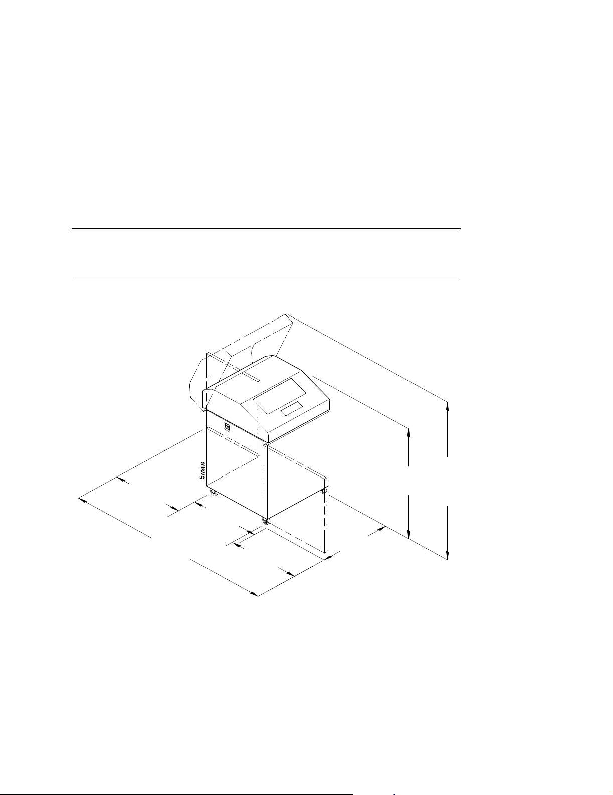
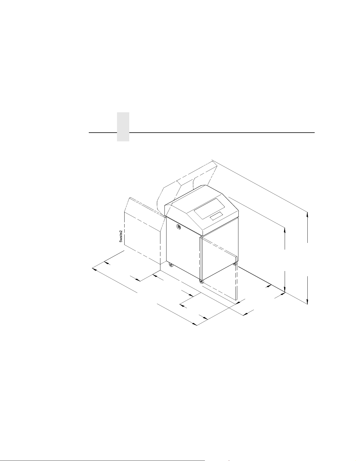
Printer Dimensions
Printer Dimensions
27.0 in
(68.84 cm)
29.0 in
(73.7 cm)
83.0 in
(210.8 cm)
27.0 in
(68.6 cm)
Figure 1. Printer Dimensions - Cabinet Model
27.0 in
(68.6 cm)
41.0 in
(104 cm)
57.5 in
(146.1 cm)
23
Page 24
Chapter 2 Printer Dimensions
27.0 in
(68.6 cm)
32.5 in
(82.6 cm)
83.0 in
(210.8 cm)
27.0 in
(68.6 cm)
59.0 in
(149.9 cm)
42.5 in
(107.8 cm)
27.0 in
(68.6 cm)
32.0 in
(81.3 cm)
24
Figure 2. Printer Dimensions - Cabinet Model with Paper Stacker
Page 25
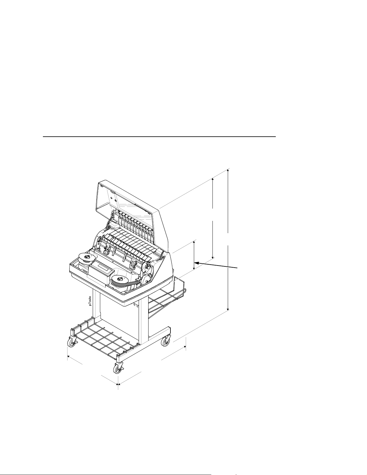
25 in.
(63.5 cm)
Printer Dimensions
48.0 in.
(122 cm)
10.5 in.
(26.67 cm.)
24.6 in.
(62.48 cm)
30 in.
(76.2 cm.)
Figure 3. Printer Dimensions - Pedestal Model
25
Page 26
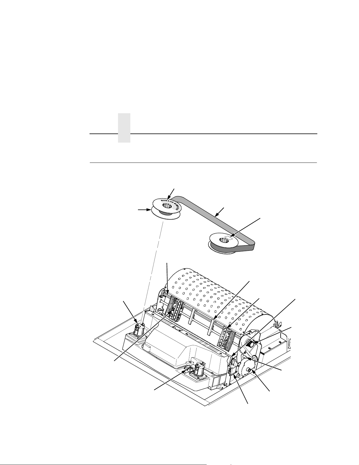
Chapter 2 Printer Component Locations
Printer Component Locations
Barcode
Ribbon Spool
Ribbon Hub
Blue Tractor
Lock (2)
Splined
Shaft
Ribbon
Date Code Label
Paper Support
Tractor (2)
Hammer Bank
Cover and
Ribbon Mask
Vertical
Position Knob
Platen Lever
26
Barcode Sensor
Figure 4. Printer Component Locations
Platen Stop
Ribbon Guide (2)
Page 27

3 Operating The Printer
Powering On The Printer
When you power on the printer, it executes a self-test. The default
power-up state is online. When the self-test completes and the
software has initialized successfully, the status indicator light turns
on, indicating the printer is online. The default value of the type of
emulation you have installed appears upper right corner of the
display. The ribbon life remaining is shown on the second line.
If there is a fault during the self-test, the status indicator flashes and
a specific fault message appears on the display (such as “LOAD
PAPER”). The alarm also sounds if it is configured to do so.
See “ LCD Message Troubleshooting Table” on page 317 for
information on fault messages and solutions.
Operating Modes
Online. In online mode, the printer can receive and print data sent
from the host. Pressing the ON LINE key toggles the printer from
offline to online mode. The status indicator is lit in online mode.
Offline. In offline mode, you can perform operator functions, such
as loading paper and setting top-of-form. You can also move within
the printer configuration menus. Pressing the ON LINE key toggles
the printer from online to offline mode. The status indicator is off in
offline mode.
Fault. In fault mode, a condition exists which must be cleared
before printing can continue. The status indicator flashes, the alarm
27
Page 28
Chapter 3 The Control Panel
beeps (if configured to sound), and a descriptive fault message
displays.
The current operating mode can be selected via control panel keys
or can result from routine operations such as powering on the
printer.
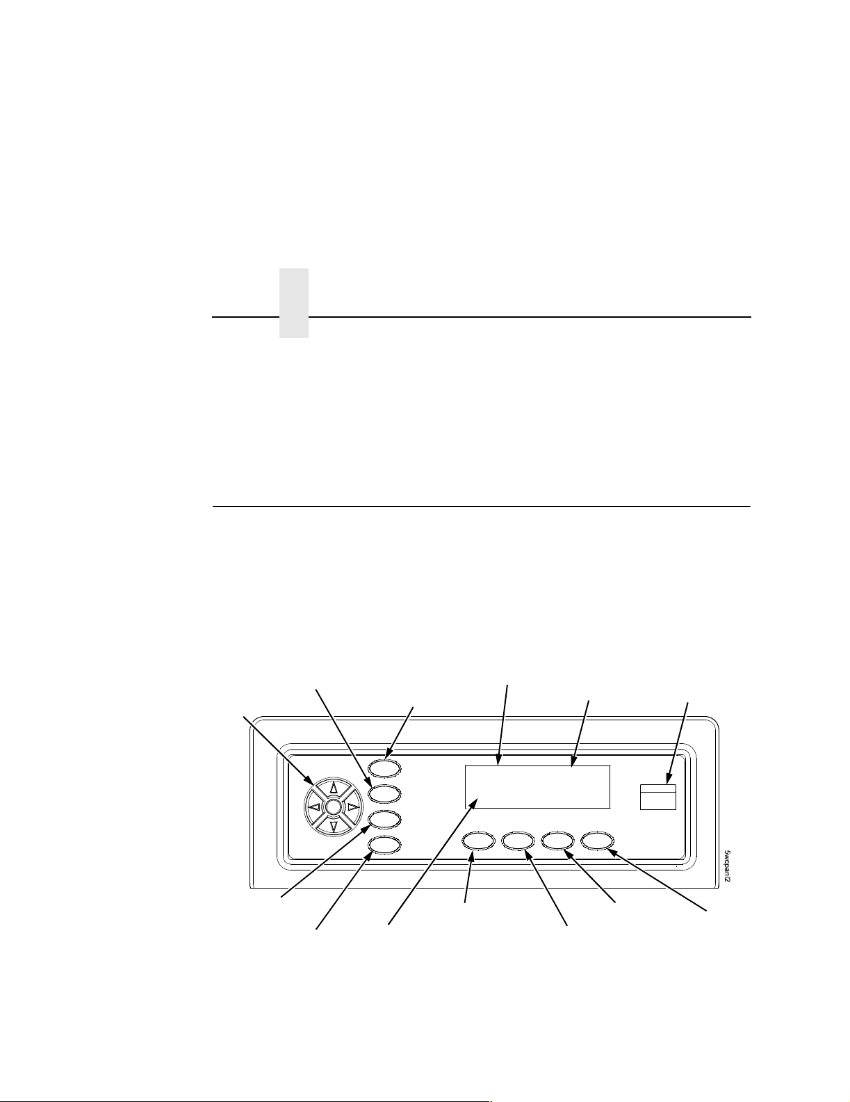
The Control Panel
Figure 5 shows the keys, displays, and indicators as they appear
on the control panel. The following section provides the
descriptions, and functions of the control panel keys.
Key combinations are indicated with the plus (+) sign. For example,
“Press
same time.
+ ” means to press the key and the key at the
Circular
Pad
JOB SELECT
28
PRT CONFIG
ENTER
SET TOF
Ribbon Life
Indicator
Figure 5. Control Panel
Message Display
ONLINE <PGL>
RIBBON LIFE = 100%
ON LINE/CLEAR
Emulation
VIEW/EJECT
PAPER ADVANCE
Status Indicator
CANCEL
Page 29

Control Panel Keys
Control Panel Keys
ON LINE / CLEAR
Toggles the printer between online and offline modes. If a fault
condition exists, pressing this key will clear the fault message and
return the printer from fault mode to offline mode.
NOTE: If the fault condition is not corrected
key, the fault message will reappear when attempting to
place the printer online.
PAPER ADVANCE
Performs advance to top-of-form, as defined by the current active
form length. The key works both online and offline.
before
pressing this
• If online with data in the printer buffer, the data will print and
then the paper will move to the next top-of-form.
• In the fault state, PAPER ADVANCE will advance the paper.
The first press moves to the top of the next available form. All
subsequent presses advances one forms length as defined by
the current active forms length.
VIEW / EJECT
When the printer is online or offline, pressing this key executes the
view or eject function, depending on whether the printer is a cabinet
or a pedestal (or zero tear pedestal).
If online with data in the printer buffer, the data prints and the key
functions as described below.
If in a fault state, this key will be ignored.
• View Function — for cabinet models, pressing the
VIEW/EJECT key moves the last data printed to the tractor
area for viewing. While in the view state, the message "Printer
in View" displays, pressing the UP or DOWN arrow keys moves
the paper up or down in 1/72 inch increments. This is done to
align the image within a pre-printed form, for example. Refer to
the UP and DOWN key functions for additional details on the
29
Page 30

Chapter 3 The Control Panel
microstep feature. Pressing VIEW/EJECT a second time
moves the paper back to the adjusted print position.
Eject Function — for pedestal models, when the VIEW/EJECT key
is pressed, the bottom of the last printed form will move to the tear
bar position. The message "READY TO TEAR/EJECT To Return"
displays. While in this position, pressing the UP or DOWN arrow
keys moves the paper up or down in 1/72 inch increments. Refer to
the Up and Down key functions for additional details on the
microstep feature. When the VIEW/EJECT key is pressed a second
time, the printer will move the paper to enable printing on the next
available form.
CANCEL
In offline mode, this key cancels all data in the print buffer, if
enabled in “ADVANCED USER” on page 281. The print buffer is
cleared without printing any of the data and the current paper
position is set as the top-of-form. If this function is disabled, the
CANCEL key will be ignored.
30
NOTE: Use of this key will cause loss of data
SET TOF
Sets the top-of-form on the printer. This key is active only when the
printer is offline and will not operate if the printer is in a fault
condition. The paper moves down to the print position and aligns to
the top-of-form. Refer to the
instructions on how to set the top-of-form.
NOTE: If there is any data in the buffer, the paper will move to the
last print position.
PRT CONFIG
In offline mode, PRT CONFIG prints the current short configuration.
This key requires a confirmation with the ENTER key; pressing any
other key will exit from this function. See “The Configuration
Menus” on page 53 for an explanation of configuration menus.
Quick Setup Guide
.
for complete
Page 31

Control Panel Keys
JOB SELECT
In offline mode, this key allows you to change the active
configuration if multiple configurations have been saved or the
typeface of the printer.
ENTER
When navigating the configuration menus, ENTER selects the
currently displayed option value as the active value. An asterisk (*)
appears next to the active value on the display. ENTER is also
used for starting and stopping printer tests and generating a
configuration printout.
NOTE: The ENTER key must be unlocked in order to function.
See UP + DOWN, below.
The ENTER key lock and unlock function can be
configured to be a key combination other than
(see page 288).
= + >
UP or DOWN (
Moves up or down between levels in the configuration menus and
makes vertical forms adjustment. After pressing VIEW, press
= or > )
= or
> to adjust the paper up or down in 1/72 inch increments for fine
vertical forms alignment. When the printer is in offline mode, press
= or > to move through levels in the configuration menus.
UP + DOWN (
Locks and unlocks the ENTER key.
NOTE: The ENTER key lock and unlock function can be
= + > )
configured to be a key combination other than
(see page 288).
= + >
31
Page 32

Chapter 3 The Control Panel
PREV or NEXT ( ; or < )
Moves between the options on the current level of configuration
menu. In the configuration menu, press
< to scroll forward through the menu selections on the same
press
level.
; to scroll backward or
PREV + NEXT (
When both keys are pressed simultaneously, the printer will reset to
the power-up configuration and reset its internal state.
; + < )
= + ON LINE (IPDS Emulation only)
In offline mode, press = + ON LINE. If there is data in the printer
buffer, the printer will be placed in online mode, print one page, and
return to the offline mode. This action can be repeated until the end
of a print job. Only one page prints each time you press
= + ON LINE. If there is no data in the printer buffer, the printer is
placed in online mode.
In the fault state,
= + ON LINE does not work.
= + PAPER ADVANCE (IPDS Emulation only)
In offline mode, press
perform a reverse linefeed. If you hold down the
ADVANCE keys for longer than 1/2 second, the printer moves to
the previous top-of-form position. If there is data in the printer
buffer, the data does not print.
In the fault state,
= + PAPER ADVANCE. The printer will
= + PAPER
= + PAPER ADVANCE does not work.
32
Page 33

= + VIEW (IPDS Emulation only)
Control Panel Keys
In offline mode, press
buffer, the printer will be placed in online mode, print one line, and
return to offline mode. This action can be repeated until the end of
the job. This function prints only one line of text. If the data is not
text, only 1/6 inch prints. If there is no data in the printer buffer, the
printer is placed in online mode for one second and then returns to
offline mode.
In the fault state,
Ribbon Life Indicator
Indicates life remaining of the currently installed ribbon. The default
settings for this feature should match the requirements for most
applications; no special user setup is needed. If your particular
application requires darker printing or can tolerate lighter printing,
the ribbon end point can be adjusted as appropriate. Please refer
“Ribbon End Point” on page 80.
= + VIEW. If there is data in the IPDS printer
= + VIEW does not work.
33
Page 34

Chapter 3 Operational Procedures
Operational Procedures
This section contains routine printer operating procedures on how
to:
• reload paper
• unload paper
• cancel a print job.
Reload Paper
Do this procedure when “LOAD PAPER” displays. (This message
occurs when the last sheet of paper passes through the paper slot.)
This procedure reloads paper without removing the last sheet of the
old paper supply, while retaining the current top-of-form setting.
Paper Slot
Metal Paper Guide
(P7220 Only)
Cabinet Models Pedestal Models
Figure 6. Paper Slot Location
34
Paper Slot
Page 35

Reload Paper
1. Raise the printer cover. Raise the platen lever as far as it will
go. (See Figure 4 on page 26 for the location of the lever.)
2. Press ON LINE/CLEAR to turn off the alarm. Do not open the
tractor doors or remove the existing paper.
3. For cabinet models, open the front door. Align the paper supply
with the label on the floor. Ensure the paper pulls freely from
the box.
4. Feed the paper up through the paper slot (see Figure 6). It may
be easier to feed one corner of the new paper up through the
slot first. When this corner can be grasped from the top, rotate
the paper back to the normal position.
NOTE: If you are using thick, multi-part forms and are unable to
load the new paper over the existing paper, go to step 16.
5. Hold the paper to prevent it from slipping down and through the
paper slot.
35
Page 36

Chapter 3 Operational Procedures
New Paper
Existing Paper
Figure 7. Loading New Paper into the Printer
6. Pull the new paper above and behind the ribbon mask, but in
front of the existing paper. See Figure 4 on page 26 for the
ribbon mask location. If necessary, gently press the existing
paper back.
36
7. Align the top edge of the new paper with the top perforation of
the existing paper.
8. Load the new paper over the existing paper. Open and load the
tractors one at a time to prevent the paper from slipping.
NOTE: Make sure that the top edge of the new paper lines up with
the top horizontal perforation of the last page.
Page 37

Vertical Position
Knob
Reload Paper
Paper Thickness
Indicator
Platen Stop
Platen Lever
9. Turn the vertical position knob to feed the paper up into the
10. Turn the platen stop knob clockwise or counterclockwise to
NOTE: If you are using the same thickness of paper, there is no
A
A
Platen Stop
Knob
Figure 8. Setting the Platen Lever
paper guide assembly, removing the last printed sheet.
match the paper thickness. (The A-B-C scale corresponds
approximately to 1-, 3-, and 6-part paper thickness).
need to readjust.
11. Lower the platen lever until it stops.
12. Press ON LINE/CLEAR to remove the “LOAD PAPER” fault
message from the display.
37
Page 38

Chapter 3 Operational Procedures
13. Press PAPER ADVANCE several times to make sure the paper
feeds properly beyond the tractors and over the lower paper
guide. Feed sufficient paper to ensure the paper stacks
correctly.
14. Close the printer top cover. Close the cabinet front door.
15. Press ON LINE/CLEAR
to place the printer in online mode and
resume printing.
Paper Slot
Metal Paper Guide
(P7220 Only)
Paper Slot
Cabinet Models Pedestal Models
38
Figure 9. Paper Slots on the Printers
NOTE: Perform steps 16 to 33 only if you are unable to load the
new paper over the existing paper.
16. Open both tractor doors.
17. Remove the old paper from the tractors. Allow the paper to fall
into the paper supply area.
18. Feed the new paper up through the paper slot. Hold the paper
to prevent it from slipping down through the paper slot.
Page 39

Left Tractor Lock
Reload Paper
Left Tractor Door
Paper
Figure 10. Loading Paper on the Left Tractor
19. Pull the paper above and behind the ribbon mask. See Figure 4
on page 26 for the ribbon mask location.
20. Load the paper on the left tractor.
21. Close the tractor door.
39
Page 40

Chapter 3 Operational Procedures
Tractor Splined
Figure 11. Positioning the Left Tractor to Avoid Damage
CAUTION
Shaft
Tractor
Paper
Scale
To avoid damage to the printer caused by printing on the
platen, always position the left tractor unit directly to the left of
the “1” mark on the paper scale.
40
22. Normally, you should not need to adjust the position of the left
tractor. If adjustment is necessary, unlock the left tractor. Slide
the tractor until it is directly to the left of the number “1” on the
paper scale and lock it. (You can also use the paper scale to
count columns.)
Page 41

Tractor Door
Tractor Lock
Figure 12. Loading Paper onto the Sprockets
Reload Paper
23. Unlock the right tractor.
24. Load the paper onto the sprockets and close the tractor door. If
necessary, slide the right tractor to remove paper slack or to
adjust for various paper widths. Then, lock the tractor.
41
Page 42

Chapter 3 Operational Procedures
Upper Paper
Upper Paper
Guide
Guide
Upper Paper
Guide
Wire
Guide (2)
Paper
Slot
42
Cabinet Model Pedestal Model
Figure 13. Using the Paper Guide to Orient the Paper
25. Pedestal models:
Using the vertical position knob to move the paper up, guide
the paper over the upper paper guide and through the slot to
the rear of the top cover. For pedestal models with the Quick
Access Cover, refer to the
Quick Setup Guide
for paper exiting
options.
26. Press PAPER ADVANCE several times to make sure the paper
feeds properly beyond the tractors and over the lower paper
guide. Feed sufficient paper to ensure the paper stacks
correctly.
27. Cabinet models:
Open the cabinet rear door. Make sure the paper is aligned
with the label in the output area (inside the cabinet). Close the
front and rear doors.
Page 43

TOF Indicator
Reload Paper
Perforation
Vertical Position Knob
Figure 14. Aligning the Perforation with the TOF Indicator
28. Align the top of the first print line with the TOF indicator on the
tractor by rotating the vertical position knob. For best print
quality, it is recommended that the top-of-form be set at least
one print line or more below the perforation.
NOTE: For exact positioning, press the VIEW/EJECT key to move
the last data printed to the tractor area for viewing. While in
View mode “Printer in View” displays. Press the Up or
Down Arrow keys to move the paper vertically in small
increments. Pressing the VIEW/EJECT key a second time
moves the paper back to the adjusted print position. The
key works both online and offline provided that the printer is
in View mode. (This procedure is applicable for both the
cabinet and pedestal models.)
43
Page 44

Chapter 3 Operational Procedures
Vertical Position
Knob
A
Platen Stop
Paper Thickness
Indicator
A
44
Platen Lever
Platen Stop
Knob
Figure 15. Adjusting the Platen Lever
29. Turn the Auto Platen Stop Knob clockwise or counterclockwise
to match the paper thickness. (The A-B-C scale corresponds
approximately to 1-, 3-, and 6-part paper thickness. Adjust until
you have the desired print quality).
NOTE: The platen stop allows you to set an optimum and
consistent thickness that is not affected when opening and
closing the platen lever.
30. Lower the platen lever until it stops.
31. Press ON LINE/CLEAR to clear any fault messages (such as
“LOAD PAPER”) from the LCD.
32. Press SET TOF. The top-of-form you have set moves down to
the print position. If there is data in the buffer, the paper moves
forward to the last print position on the next page.
33. Press ON LINE/CLEAR and close the printer cover.
Page 45

Unload Paper
Unload Paper
1. Press ON LINE/CLEAR to place the printer in offline mode and
open the printer cover.
2. For cabinet models, open the cabinet rear door. For models
with the power stacker installed, press the STACKER UP key
on the rear control panel.
Paper
Perforation
Figure 16. Unloading the Paper from the Printer
3. Tear off the paper at the perforation.
4. Allow the paper to fall to the back of the printer and into the
paper stacking area.
5. For pedestal models, remove the stacked paper from the paper
tray.
45
Page 46

Chapter 3 Operational Procedures
Paper
Power Stacker
46
Figure 17. Removing Stacked Paper from the Printer
6. For cabinet models, remove the stacked paper from the rear
cabinet floor. For cabinet models with the power stacker
installed, remove the paper from the wire paper tent and press
the STACKER DOWN key to lower the stacker mechanism.
7. Close the cabinet rear door.
Page 47

Tractors Doors (2)
Platen Lever
Unload Paper
CAUTION
Figure 18. Completely Removing the Paper
8. To completely remove the paper from the printer:
a. Raise the platen lever as far as it will go and open both
tractor doors.
Be careful when pulling any paper backward through the
paper path, especially when using a label stock. If you are not
careful, labels can detach and adhere to the printer within the
paper path, where only an authorized service representative
can remove them.
b. Open the cabinet front door.
c. Gently pull the paper down through the paper slot. Allow
the paper to fall into the paper supply area.
d. Remove the paper from the paper supply area.
47
Page 48

Chapter 3 Integrated Print Management System
Integrated Print Management System
The P7000’s Integrated Print Management System feature
automatically monitors and communicates the status of the ribbon’s
life to help the operator know when to change ribbons. Using a
special bar coded spool, the P7000 automatically detects when a
new or used ribbon is installed and determines the ribbon’s length,
ink color, and expected yield. The ribbon life, starting from 100%
when new and decreasing to 0% when depleted, is always
displayed on the control panel. See Figure 5 on page 28.
When the ribbon life reaches 2%, a warning message “RIBBON
UNDER 2%/Change RBN soon” appears on the control panel
display. The control panel status indicator lamp flashes. The printer
will continue printing in this condition until the ribbon life reaches
0% at which time, printing will stop. The ribbon may be changed at
any time while the printer is in the “RBN END POINT/Change
Ribbon” condition without losing data in the printer’s buffer. Simply
follow the procedures outlined below to change the ribbon.
48
You may also resume printing for approximately two more minutes
without changing the ribbon by pressing the ON LINE/CLEAR key
twice. This may be done as many times as needed to complete the
job in progress.
Lighter Or Darker Print
The ribbon life value as determined by the Integrated Print
Management System is factory set so that the image quality at the
end of the ribbon life is as good as it was when the ribbon was new.
You may adjust the ribbon end point for a lighter or darker image as
required for your printing needs. See “PRINTER CONTROL” on
page 276.
Page 49

Blue Tractor
Door (2)
Changing Ribbons
Changing Ribbons
Before changing the ribbon, determine whether you want to make
the print lighter (extend the ribbon life) or darker (shorten the ribbon
life). If you want to make the print lighter, go to “Ribbon End Point”
on page 277 and follow the procedures for adjusting the image
density. If you are satisfied with the print darkness, or if you want to
increase the darkness at the end of ribbon life, continue with the
following steps.
Platen Lever
Figure 19. Preparing to Load the Ribbon
1. Open the printer cover.
2. Raise the platen lever as far as it will go.
3. Close the tractor doors.
4. Remove the old ribbon and discard properly.
49
Page 50

Chapter 3 Integrated Print Management System
Date Code Label
Spool
Right Hub
IMPORTANT
50
Figure 20. Loading the Barcoded Ribbon
5. Place the full spool on the right hand side ribbon hub and press
it into place.
The full spool has a barcode label on the bottom side and a
date code label on the top. Once the sensor reads and logs the
ribbon barcode, the Integrated Print Management System
starts to track ribbon usage. A date code label is on the top
side of the right hand spool.
If you remove the ribbon during the course of its life and want
to re-install the same ribbon, be sure to place the same spools
on the correct hubs.
Page 51

Ribbon Spool
Left Hub
Changing Ribbons
A
Ribbon Loading
Instructions For
Future Reference
Figure 21. Threading the Ribbon Around the Ribbon Guide
Hammer
Bank Cover
Ribbon Mask
A
Ribbon Guide
(Both Sides)
6. Thread the ribbon around the ribbon guide and along the ribbon
path. Be sure to thread the ribbon between the hammer bank
cover and the ribbon mask.
7. Place the empty spool on the left hub.
8. Press the spool down until it snaps into place.
51
Page 52

Chapter 3 Integrated Print Management System
9. Turn the left spool by hand to make sure the ribbon tracks
correctly in the ribbon path and around the ribbon guides.
10. Close the platen lever.
11. Close the printer top cover.
If you want to increase the darkness level of the ribbon at the end of
life, go to “Ribbon End Point” on page 277 and follow the
procedures for adjusting the image density.
If you are satisfied with the print darkness, press the
ON LINE/CLEAR key twice to return the printer to operation.
Cancel A Print Job
The procedure to cancel a print job depends on the printer
emulation and your application software. Contact your system
administrator for additional information.
1. If the printer is online, press ON LINE/CLEAR to place the
printer in offline mode.
52
2. From the host system, stop the print job.
NOTE: If the print job is not stopped from the host system before
pressing CANCEL, the print job continues with data
missing when the printer returns to online mode. Exercise
caution to prevent unwanted data loss occurrences, as this
function deletes unprinted data in the printer. This function
is active only in offline mode; the purpose of this function is
to eliminate the necessity of printing unwanted data when
print jobs are canceled.
3. Press CANCEL.
NOTE: You may need to enable the Cancel option on the front
panel. See “ADVANCED USER” on page 281 for details.
4. Set the top-of-form. Refer to the Quick Setup Guide.
Page 53

4 The Configuration
Menus
Configuration Overview
To print data, the printer must respond correctly to signals and
commands received from the host computer. Configuration is the
process of matching the printer's operating characteristics to those
of the host computer and to specific tasks, such as printing labels or
printing on different sizes of paper. The characteristics which define
the printer's response to signals and commands received from the
host computer are called configuration parameters.
You can configure the printer using the configuration menus and
the control panel or by sending control codes in the data stream
from a host computer attached to the printer. This chapter provides
an introduction to configuring the printer and includes the
configuration menus available (depending on which emulation you
have installed in the printer).
IMPORTANT
Configuration directly affects printer operation. Do not change
the configuration of your printer until you are thoroughly
familiar with the procedures in this chapter.
53
Page 54

Chapter 4 Configuration Overview
Changing Parameter Settings
You may change a printer parameter setting, such as line spacing
or forms length, either by pressing keys on the control panel or by
sending emulation control codes in the data stream from a host
attached to the printer. The control panel allows you to configure
the printer’s resident set of configuration menus. An example
procedure for using the control panel to change parameter settings
begins on page 57.
When control codes are sent from a host attached to the printer,
they override control panel settings. For example, if you set the line
spacing to 6 lpi with the control panel, and application software later
changes this to 8 lpi with a control code, the control code overrides
the control panel setting.
Saving Parameter Settings
The parameter settings that you have changed using the menus
and control codes will be permanently stored in the printer’s
memory. Changes made to the Factory Default configuration menu
items will always be written to the first available Config (#) where #
equals the next available unassigned configuration number and can
be made with or without the Protect Config option disabled.
54
You may also save your new configurations using the PTX_SETUP
command host control code. See your
Programmer’s Reference Manual
LinePrinter Plus
for details.
Page 55

Default And Custom Configurations
Default And Custom Configurations
A configuration consists of a group of parameter settings, such as
line spacing, forms length, etc. Your printer provides a fixed default
configuration and allows you to define several custom
configurations for use with particular print jobs.The factory default
configuration can be loaded, but it cannot be altered.
Eight configurations can be modified for unique print job
requirements. The “Save Config.” option allows you to save eight
groups of parameter settings in memory as custom configurations
numbered from 1 through 8. An explanation on how to save a set of
parameter values as a custom configuration using the “Save
Config.” menu option begins on page 61.
55
Page 56

Chapter 4 Configuration Overview
Navigating The Menus
To manipulate configurations review the following instructions
about navigating through the menus.
You must be offline to move within the menus.
ON LINE/CLEAR
OR
OR
ENTER
+
Press to toggle between ONLINE and
OFFLINE. Menus are accessed with the
printer offline.
Press to move up or down through the menu
levels.
Press to scroll through the available choices
on a chosen level.
Press to confirm selection.
Press to lock and unlock the ENTER key. The
ENTER key is locked by default to prevent
you from accidentally changing the printer
configuration. The lock and unlock function
can be configured to be other than
= + > (See
“Set Lock Key” on page 288.)
56
To experiment with navigating the menus, use the example on the
next page as a tutorial.
Page 57

Changing Parameters Example
Changing Parameters Example
OFFLINE
QUICK
SETUP
. . .
PRINTER
CONTROL
Ribbon End
Point
Darker +6
Darker +5
Darker +4
Darker +3
Darker +2
Darker +1
Normal*
Lighter -1
Lighter -2
Lighter -3
Lighter -4
Lighter -5
Lighter -6
Lighter -7
Lighter -8
Lighter -9
Lighter -10
Open Platen
@ BOF
Disable*
Enable
Unidirectional
Disable*
Enable
Barcode
Quality
Dark*
Draft
Display
Language
English
German
French
Italian
Spanish
Portuguese
* = Factory Default
Tear Bar
Dist.
7.46 in.*
(4.5-10.5 in.)
Accented
Char
Standard*
Tall
A configuration consists of several parameters. The default factory
configuration has a starting set of parameters. In the configuration
menu above, and in all the configuration menus in this chapter, the
factory default values are indicated by an asterisk (*).
Your print jobs may require parameter values which vary from the
default settings. This section provides an example procedure for
changing individual parameter values.
The following procedure shows how to change and save the
settings for the Barcode Quality and Language options. Use these
guidelines to navigate the configuration menus and change other
parameters.
57
Page 58

Chapter 4 Configuration Overview
Step Press LCD Notes
1. Make sure the printer is on.
2. OFFLINE
3. ENTER SWITCH
ON LINE/CLEAR
QUICK SETUP
UNLOCKED
+
OFFLINE
4. OFFLINE
UNTIL
5. PRINTER CONTROL
6. PRINTER CONTROL
UNTIL
QUICK SETUP
PRINTER CONTROL
Ribbon End Point
Barcode Quality
Allows you to make
configuration changes.
58
7. Barcode Quality
Dark*
Page 59

Changing Parameters Example
Step Press LCD Notes
8. Barcode Quality
Draft
OR
9. Barcode Quality
10. PRINTER CONTROL
11. PRINTER CONTROL
12. Display Language
13. Display Language
ENTER
Draft*
Barcode Quality
Display Language
UNTIL
English*
Spanish
Cycle through the
choices.
The * indicates this choice
is active.
Press until the desired
parameter displays.
OR
14. Display Language
15. ENTER SWITCH
ENTER
Spanish*
LOCKED
+
The * indicates this choice
is active.
Locks the ENTER key.
59
Page 60

Chapter 4 Configuration Overview
Step Press LCD Notes
16. ENTER = Save
17A. Cfg = 1*
17B. ONLINE
18. The printer is ready for operation
ON LINE/CLEAR
ENTER
ON LINE/CLEAR
ONLINE = No Save
= Power-Up Cfg
Ribbon Life = 100%
Auto Save Configuration
After any changes are made to the Factory Default configuration
menu items, you will be prompted to save the changes to “Config
#”, where # equals the next available unassigned configuration
number. If you do not select this option, the printer will be brought
ONLINE and the changes will be implemented but saved only
temporarily until deliberately saved as a new configuration or until
you power off the printer.
Press ENTER to
automatically save
configuration changes.
Press ONLINE to
continue without saving.
Configuration changes
have been saved as
Configuration 1, and will
be set as the Power-Up
config. The printer will
then be brought online.
Places the printer online
without permanently
saving the configuration
changes.
60
Page 61

Saving Your New Configuration
Saving Your New Configuration
The Save Config. option allows you to save up to eight custom
configurations to meet different print job requirements. Once you
have changed all of the necessary parameters, you may save them
as a numbered configuration (Example 1 on page 62) or a named
configuration (Example 2 on page 65) that can be stored and
loaded later for future use. If you do not save your configuration
using the Auto Save, or this option, all of your parameter changes
will be erased when you power off the printer.
Once you have saved a custom configuration using this option, it
will not be lost if you power off the printer. You can load a
configuration for a specific print job (see “Load Config.” on
page 82). You can also modify and resave it. You may want to print
your configurations (see “Print Config.” on page 83) and store them
in a safe place, such as inside the printer cabinet. If the Protect
Configs. parameter is enabled and you try to resave an existing
configuration, the new configuration will not be saved until the
existing configuration has been deleted (see “Delete Config.” on
page 83).
NOTE: Once you change active emulations, any changes to the
previously selected emulation will be gone unless they
have been saved.
61
Page 62

Chapter 4 Configuration Overview
Example 1
This example shows how to save a configuration as a numbered
configuration, then later print it.
Step Press LCD Notes
1. Make sure the printer is on.
2. OFFLINE
3. ENTER SWITCH
ON LINE/CLEAR
CONFIG. CONTROL
UNLOCKED
+
OFFLINE
QUICK SETUP
4. OFFLINE
CONFIG. CONTROL
UNTIL
5. CONFIG. CONTROL
6. CONFIG. CONTROL
UNTIL
Load Config.
Save Config.
Allows you to make
configuration changes.
62
7. Save Config.
1*
Page 63

Saving Your New Configuration
Step Press LCD Notes
8. Save Config.
2
OR
9. Save Config.
NOTE: We recommend that you print the configuration. To print the configuration go to Step 9. To
skip this procedure and resume printer operation, go to Step 14.
10. CONFIG. CONTROL
11. CONFIG. CONTROL
12. Print Config.
ENTER
UNTIL
2*
Save Config.
Print Config.
Current
Cycle through the
choices.
The * indicates this choice
is active.
13. Print Config.
OR
14. OFFLINE
ENTER
2
CONFIG. CONTROL
Press until the desired
parameter displays.
The selected
configuration is printed.
63
Page 64

Chapter 4 Configuration Overview
Step Press LCD Notes
15. ENTER SWITCH
LOCKED
Locks the ENTER key.
+
16. ONLINE
17. If you printed out the configuration, store it in a safe place. The printer is ready for
ON LINE/CLEAR
operation.
Ribbon Life = 100%
64
Page 65

Saving Your New Configuration
Example 2
This example shows how to save a configuration as a named
configuration.
Step Press LCD Notes
1. Make sure the printer is on.
2. OFFLINE
3. ENTER SWITCH
ON LINE/CLEAR
CONFIG. CONTROL
UNLOCKED
+
OFFLINE
QUICK SETUP
4. OFFLINE
CONFIG. CONTROL
UNTIL
5. CONFIG. CONTROL
6. CONFIG. CONTROL
UNTIL
Load Config.
Name Configs.
Allows you to make
configuration changes.
7. Name Configs.
1
The LCD flashes.
65
Page 66

Chapter 4 Configuration Overview
Step Press LCD Notes
8. Name Configs
2
UNTIL
9. 2
2*
10. 2
UNTIL
11. 2
12. 2
UNTIL
13. 2
T
T_
TE
TE_
You will rename config 2.
Cycle through the choices
until “T” displays.
Saves the first character.
Cycle through the choices
until “E” displays.
Saves the second
character.
66
14. 2
UNTIL
15. 2
TES
TES_
Cycle through the choices
until “S” displays.
Saves the third character.
Page 67

Saving Your New Configuration
Step Press LCD Notes
16. 2
UNTIL
17. 2
18. Name Configs
19. CONFIG. CONTROL
20. CONFIG. CONTROL
21. Save Config.
ENTER
UNTIL
TEST
TEST_
TEST
Name Configs
Save Config.
1*
Cycle through the choices
until “T” displays.
Saves the fourth
character.
The configuration is
renamed TEST.
22. Save Config.
TEST
23. Saving Configuration
ENTER
Save Config.
TEST*
TEST now appears as
one of configuration
choices.
Your configuration is
saved as TEST.
67
Page 68

Chapter 4 Configuration Overview
Step Press LCD Notes
24. ENTER SWITCH
LOCKED
+
25. ONLINE
ON LINE/CLEAR
Now you have the saved configuration for later use if needed.
Ribbon Life = 100%
Optimizing Print Quality
LP+, IGP/PGL, and IGP/VGL Emulations
You can optimize print quality for darker and sharper barcodes and
characters. Doing so, however, will decrease the printer speed.
To optimize print quality, you can change the values of the following
configuration parameters:
• Bar Code Quality (Printer Control menu): Select “Dark” or
“Recommended.” Recommended prints the darkest images,
but at the slowest speed. Dark prints at a faster speed than
Recommended, but the characters are not as dark. (See page
279 for a written description of Bar Code Quality.)
Locks the ENTER key.
68
• Print Quality (IGP/PGL emulation): Select “Best” or “High.”
Best prints the darkest images, but at the slowest speed. High
prints at a faster speed than Best, but the characters are not as
dark. (See page 129 for the IGP/PGL Configuration Menu, and
see page 143 for a written description of Print Quality.)
• Print Quality (IGP/VGL emulation): Select “High.” (See page
148 for the IGP/VGL Configuration Menu, and see page 157 for
a written description of Print Quality.)
Page 69

Optimizing Print Speed
Optimizing Print Speed
LP+, IGP/PGL, and IGP/VGL Emulations
The printer has been configured at the factory for optimal print
speed. To optimize print quality instead, you can change values for
specific configuration parameters such as Barcode Quality and
Print Quality. Doing so, however, will decrease the printer speed.
If you have optimized the printer for print quality, you can change it
to optimal speed by selecting the values as follows:
• Bar Code Quality (Printer Control menu): Select “Draft.”
(See page 70 for the Configuration Main Menu, and see page
279 for a written description of Bar Code Quality.)
• Print Quality (IGP/PGL emulation): Select “Dataprocessing.”
(See page 129 for the IGP/PGL Configuration Menu, and see
page 143 for a written description of Print Quality.)
• Print Quality (IGP/VGL emulation): Select “Dataprocessing.”
(See page 148 for the IGP/VGL Configuration Menu, and see
page 157 for a written description of Print Quality.)
Coax/Twinax Emulation
You can increase print speed by selecting the Enable mode for the
Early Print Complete configuration parameter in the Coax/Twinax
Emulation. However, if an error occurs while in Enable mode, you
may lose data. For more information, refer to “Early Print Complete”
on page 172. (For the Coax/Twinax Emulation menu, refer to
page 167.)
69
Page 70

Chapter 4 Main Menu
Main Menu
OFFLINE
QUICK
SETUP
page 73
Host Interface
Device ID
2
Adapter Address
Ethernet Address
WLAN Address
1
Active IGP Emul
PGL SFCC
Printer Protocol
Form Length
Form Width
P-Series SFCC
Margins
Form Length
Form Width
Vert Forms
Horiz Forms
Page Length Rep.
Max Line Width
4
4
4
4
5
5
5
6
6
7
Ribbon End Point
Save Config
Power Up Config
CONFIG.
CONTROL
page 82
Load Config.
Save Config.
1
Print Config.
1
Delete Config.
Power-Up Config.
3
Protect Configs.
Name Configs
Reset Cfg Names
7
HOST
INTERFACE
page 85
Auto Switching*
Dataproducts
Centronics
Serial
1
Twinax
1
Coax
E-Net Adapter
IEEE 1284
1
Ethernet
Adapter Address
Adapter Params
Ethernet Address
Ethernet Params
WLAN Address
WLAN Params
1
NETWORK
SETUP
1
page 108
1
1
1
1
1
1
1
If installed
2
If Twinax is selected
3
If VGL is enabled
4
If LP+ is selected
5
If ANSI is installed
6
If LG is installed
7
If PCL-II is installed
ACTIVE
(IGP) EMUL
page 125
IGP/PGL*
IGP/VGL
(not shown if any
below are installed)
ANSI (if installed)
PCL-II (if installed)
LG (if installed)
LP+ (with any above)
70
Figure 22. Main Menu Configuration
Page 71

Optimizing Print Speed
Main Menu
EMULATION
page 166
1
CTHI
LinePrinter+
44/48XX-ANSI
IGP/PGL
IGP/VGL
IPDS
LG
PCL-II
1
1
1
1
1
PRINTER
CONTROL
page 276
Ribbon End Point
Eject Function
1
Open Platen @ BOF
Barcode Quality
Tear Bar Dist.
Unidirectional
Display Language
Accented Char
Ptx Setup Option
Hex Dump Mode
Power-up State
Downloaded Fonts
PMD Fault
Power Stacker
Auto Elevator
3
Auto Locking
File System
Set Sharing
Shuttle Timeout
Slow Paper Slew
Alarm
Power Saver Time
Pwr Save Control
Cancel Key
Set Lock Key
Ribbon Action
Ink Saver Mode
ADVANCED
USER
page 281
DIAGNOSTICS
page 289
3
Printer Tests
Test Width
Paper Out Dots
3
System Memory
1
1
3
Print Statistics
DRAM Avail.
Flash Avail.
1
If installed
2
If Ethernet is installed
3
Not available in LG or PCL-II
71
Page 72

Chapter 4 Main Menu
Brief descriptions follow for the first-level configuration menu
options:
• QUICK SETUP — These options allow quick access to the
most frequently changed or inputted parameters during the
installation of the printer.
• CONFIG. CONTROL — These options allow you to save, print,
load, delete, name, and reset entire sets of configuration
parameters.
• HOST INTERFACE — These options allow you to select either
the Serial RS-232, Serial RS-422, Centronics
Dataproducts
1284 parallel, Auto Switching, Coax or Twinax interface for the
printer. This menu also allows you to configure several
parameters for each interface.
®
parallel and Long Lines, Ethernet™, IEEE®
®
parallel,
• NETWORK SETUP — This option allows you to select from
Ethernet Address options and Ethernet Parameters options.
• ACTIVE (IGP) EMUL — This menu allows you to select the
PGL or VGL emulation from the menu if IGP is installed.
• EMULATION — This menu allows you to configure the options
which are available for the current operating (active) emulation.
For example, if LinePrinter+ is the active emulation, then the
LinePrinter+ emulation options can be configured using this
menu.
• PRINTER CONTROL — These options allow you to select
parameters common to a general user, such as display
language and Barcode quality.
• ADVANCED USER — These options allow you to select
several advanced operating parameters for the printer, such as
the speed at which paper will advance when slewing.
72
• DIAGNOSTICS — These options include the diagnostic tests,
system memory, and statistics of the printer.
Page 73

QUICK SETUP
Optimizing Print Speed
QUICK SETUP
QUICK SETUP
(from page 70)
Host
Interface
Auto Switching*
Centronics
Dataproducts
Serial
IEEE 1284
1
Coax
1
Twinax
Ethernet
1
WLAN
Address
IP Address
Subnet Mask
Gateway Address
MAC Address
DHCP
3
3
3
3
Printer
Protocol
3
Device ID
IPDS*
5225
4234-2
Active IGP
EMUL
IGP/PGL*
IGP/VGL
Form
Length
* = Factory Default
1
2
3
4
5
4
4
6
If installed
If Enet is selected
If Wireless is selected
If VGL is enabled
If VGL is selected
Adapter
Address
IP Address
Subnet Mask
Gateway Address
MAC Address
DHCP
PGL SFCC
7E*
1-FF
Form
Width
1
2
2
2
2
10
6
6
If LP+ is selected
7
If ANSI is installed
8
If LG is installed
9
If PCL-II is installed
10
If PGL is selected
Ethernet
Address
IP Address
Subnet Mask
2
Gateway Address
MAC Address
2
DHCP
VGL SFCC
5E*
Select CPI
1
2
2
2
2
5
P-Series*
P-Series XQ
Serial Matrix
Proprinter XL
Epson FX
Funct. of Lines
66 lines*
1-192 lines
Funct. of CPI
132 characters*
1-272 characters
10.0 CPI*
12.0 CPI
13.3 CPI
15.0 CPI
17.1 CPI
20.0 CPI
73
Page 74

Chapter 4 QUICK SETUP
QUICK SETUP
(continued)
* = Factory Default
1
If installed
2
If Enet is selected
3
If Wireless is selected
4
If VGL is enabled
5
If VGL is selected
6
If LP+ is selected
7
If ANSI is installed
8
If LG is installed
9
If PCL-II is installed
Select CPI
6.0 LPI*
8.0 LPI
10.3 LPI
Form
7
Width
Funct. of CPI
136 Characters*
(1-272)
Max Line
9
Width
13.2 Inches*
13.6 Inches
P-Series
SFCC
1*
00-7F
Forms
Bot. Frm 66/6*
(0-198)
Top Mrg 0/6*
(0-198)
Ribbon End
Point
Darker +6
Darker +5
Darker +4
Darker +3
Darker +2
Darker +1
Normal*
Lighter -1
Lighter -2
Lighter -3
Lighter -4
Lighter -5
Lighter -6
Lighter -7
Lighter -8
Lighter -9
Lighter -10
Vert
6
8
Margins
Left Margin
Right Margin
Top Margin
Bottom Margin
Left Mrg 0.00*
(0-198)
Top Mrg 0/6*
(0-198)
Save Config
1*
2 - 8
Horiz
Forms
7
8
Factory*
1 - 8
Funct. of Lines
66 Lines*
(1-192)
Page Length
Inches/Page*
Lines/Page
Power Up
Config
Form
Length
Rep
7
9
74
Page 75

Optimizing Print Speed
QUICK SETUP
Host Interface
The Host Interface menu enables you to select and configure
interfaces between the printer and your host computer.
Device ID
This parameter defines the printer emulation as IPDS, 4234-2 or
5225. After the emulation has been changed, a POR status is sent
to the host. IPDS is the default.
Adapter Address
• IP Address. A numeric address such as 123.45.61.23 which
identifies a printer or server in a LAN or WAN.
• Subnet Mask. A binary value used to divide IP networks into
smaller subnetworks or subnets. This mask is used to help
determine whether IP packets need to be forwarded to other
subnets.
• Gateway Address. A gateway address is the IP address of a
hardware device (gateway) that translates data between two
incompatible networks, which can include protocol translation.
• MAC Address. This menu item is the Manufacturer’s Assigned
Number, and is unique for each printer. It is read-only.
• DHCP. You can enable/disable the DHCP protocol using this
option, but consult your administrator for the appropriate
setting.
75
Page 76

Chapter 4 QUICK SETUP
Ethernet Address
• IP Address. A numeric address such as 123.45.61.23 which
identifies a printer or server in a LAN or WAN.
• Subnet Mask. A binary value used to divide IP networks into
smaller subnetworks or subnets. This mask is used to help
determine whether IP packets need to be forwarded to other
subnets.
• Gateway Address. A gateway address is the IP address of a
hardware device (gateway) that translates data between two
incompatible networks, which can include protocol translation.
• MAC Address. This menu item is the Manufacturer’s Assigned
Number, and is unique for each printer. It is read-only.
• DHCP. You can enable/disable the DHCP protocol using this
option, but consult your administrator for the appropriate
setting.
WLAN Address
76
• IP Address. A numeric address such as 123.45.61.23 which
identifies a printer or server in a LAN or WAN.
• Subnet Mask. A binary value used to divide IP networks into
smaller subnetworks or subnets. This mask is used to help
determine whether IP packets need to be forwarded to other
subnets.
• Gateway Address. A gateway address is the IP address of a
hardware device (gateway) that translates data between two
incompatible networks, which can include protocol translation.
• MAC Address. This menu item is the Manufacturer’s Assigned
Number, and is unique for each printer. It is read-only.
• DHCP. You can enable/disable the DHCP protocol using this
option, but consult your administrator for the appropriate
setting.
Page 77

Optimizing Print Speed
QUICK SETUP
Active IGP Emulation
The Active Emulation menu enables you to activate either the PGL
or VGL emulation.
PGL SFCC
You can specify which hex code (1-FF) will be used as the Special
Function Control Character (SFCC). The SFCC denotes that the
following data is an IGP command.
• 7E (the default)
• 1 – FF
VGL SFCC
You can specify which hex code (1-FF) will be used as the Special
Function Control Character (SFCC). The SFCC denotes that the
following data is an IGP command.
• 5E (the default)
• 1 – FF
Printer Protocol
Select the LinePrinter+ protocol you wish to use. Refer to the
LinePrinter Plus Programmer's Reference Manual
information.
for more
Form Length
Form length is the number of lines that can be printed on a page.
You can set the form length in inches, millimeters (mm), or as a
function of the current lpi (lines per inch).
Form Width
The form width can be specified in inches, millimeters, or as a
function of the current cpi (characters per inch). The forms width set
should not exceed the actual paper width.
77
Page 78

Chapter 4 QUICK SETUP
Select CPI
This parameter lets you specify the characters per inch (cpi) values.
Select LPI
This parameter lets you specify the lines per inch (lpi) values.
P-Series SFCC
This parameter allows you to select which ASCII codes will function
as the Special Function Control Code (SFCC) command delimiter.
P-Series codes can use hex 00 through hex 7F. Options include the
following:
• SOH (hex 01) (the default)
• ESC (hex 1B)
• ETX (hex 03)
• CIRCUMFLEX (hex 5E) – also called caret (^)
• TILDE (hex 7E) – (~)
78
NOTE: SOH, ETX, and ESC are non-printables. The characters (^)
and (~) are printable; however, do not use them as
printables in the host data stream if either is chosen as a
delimiter because print errors will occur.
Margins
• Left Margin. Set in columns. Column zero is defined as the far
left edge of the page, and column numbering increments from
left to right.
• Right Margin. Set in columns. Column zero is defined as the
far right edge of the page, and column numbering increments
from right to left.
• Top Mar gin. Defined in lines, starting from line zero at the top
of the page and incrementing from the top down.
• Bottom Margin. Defined in lines, starting from line zero at the
bottom of the page and incrementing from the bottom up.
Page 79

Optimizing Print Speed
QUICK SETUP
Form Length
Form length is the number of lines that can be printed on a page.
You can set the form length in inches, millimeters (mm), or as a
function of the current lpi (lines per inch).
Form Width
The form width can be specified in inches, millimeters, or as a
function of the current cpi (characters per inch). The forms width set
should not exceed the actual paper width.
Vert Forms
• Bot Frm 66/6 (default). This option sets the bottom margin for
the forms. You must specify the bottom margin in lines (at 6
lines per inch), ranging from 0 to 198 lines (33 inches). The
default setting is 66. Press the right arrow to increase the value,
left arrow to decrease the value, and ENTER to change units.
Selecting a value for this option resets the top margin to 0, so
the top margin must be redefined after this option is selected.
• Top Mrg 6/0 This option sets the top margin for the forms. You
must specify the top margin in lines (at 6 lines per inch),
ranging from 0 to 198 lines (33 inches). The default setting is 0.
Press the right arrow to increase the value, left arrow to
decrease the value, and ENTER to change units. The margins
will automatically adjust so that the top and bottom margins do
not cross each other.
79
Page 80

Chapter 4 QUICK SETUP
Horiz Forms
• Left Mgr 0.00 (default). This sets the left margin for the forms.
You must specify the left margin in 1/10 inch increments, from 0
to 13.1 inches. The default value is 0. Press the right arrow to
increase the value, left arrow to decrease the value, and
ENTER to change units. The margins will automatically adjust
so that the left and right margins do not cross each other.
• Right Mrg 0/6. This sets the right margin for the forms. You
must specify the right margin in 1/10 inch increments, from 0.1
to 13.2 inches. The default value is 13.2. Press NEXT to
increase the value, PREV to decrease the value, and ENTER
to change units. The margins will automatically adjust so that
the left and right margins do not cross each other.
Page Length Rep
• Inches/Page (default). Allows the user to set the page length in
inches.
• Lines/Page. Allows the user to set the page length in number
of lines.
80
Max Line Width
Set the maximum line width at either 13.2 inches or the maximum
width of the printer.
Ribbon End Point
This parameter adjusts the point at which the system will declare
the ribbon as being expended. The life count will always be from
100% to 0%, but if a darker setting is selected 0% will be reached
more quickly. If a lighter setting is selected, the system will extend
the time it takes to reach 0%.
Page 81

Optimizing Print Speed
QUICK SETUP
Save Config
This option allows you to save up to eight configurations to meet
different print job requirements. This eliminates the need to change
the parameter settings for each new job. The configurations are
stored in memory and will not be lost if you turn off the printer. If the
Protect Configs. parameter is enabled, the new configuration will
not be saved unless the existing configuration has been deleted
first. The factory default configuration cannot be changed. See
“Saving Your New Configuration” on page 61 for details.
Power Up Config
This option allows you to specify which of the nine configurations
(Factory or 1-8) will be the power-up configuration.
81
Page 82

Chapter 4 CONFIG. CONTROL
CONFIG. CONTROL
The CONFIG. CONTROL menu allows you to control your printer’s
configurations according to the specifications necessary for your
print jobs.
CONFIG.
CONTROL
(from page 70)
* = Factory Default
Load
Config.
Factory*
1-8
Name
Configs
1-8
Config.
1*
2-8
Reset Cfg
1*
2-8
All
Save
Names
Print
Config.
Current Short*
Current Full
Factory
Power-Up
All
1-8
1*
2-8
Delete
Config.
Power-Up
Config.
Factory*
1-8
Protect
Configs.
Disable*
Enable
Load Config.
The printer can store numerous configurations in memory. This
parameter allows you to select and load a specific configuration.
82
Page 83

CONFIG. CONTROL
Optimizing Print Speed
Save Config.
This option allows you to save up to eight configurations to meet
different print job requirements. This eliminates the need to change
the parameter settings for each new job. The configurations are
stored in memory and will not be lost if you turn off the printer. If the
Protect Configs. parameter is enabled, the new configuration will
not be saved unless the existing configuration has been deleted
first. The factory default configuration cannot be changed. See
“Saving Your New Configuration” on page 61 for details.
Print Config.
This option is used to print a listing of various stored printer
configurations. Store printouts of your configurations in a safe place
for quick referral.
Delete Config.
You can delete one or all of your eight customized configurations.
The factory default configuration cannot be deleted.
Power-Up Config.
You can specify which of the nine configurations (Factory or 1-8)
will be the power-up configuration.
Protect Configs.
You can specify whether or not a new configuration should
overwrite an existing configuration when you activate the Save
Configs. parameter. When disabled (default), the new configuration
will overwrite the existing configuration. When enabled, the new
not
configuration will
message “CONFIG. EXISTS / Delete First” displays.
overwrite the existing configuration, and the
83
Page 84

Chapter 4 CONFIG. CONTROL
Name Configs
You may specify a 15-character name which can be used to refer to
a configuration. The name you enter for a configuration will be used
in the Load Config., Save Config., Print Config., Delete Config., and
Power-Up Config. menus. The name can only be cleared by using
the Reset Cfg Names menu.
When you move into the Name Configs. menu, the top line of the
display shows the current configuration name. The second line of
the display is initially the same as the top line. You can modify the
second line of the display without affecting the top line until the
ENTER key is pressed, which sets the modified name.
Press the UP or DOWN (
available for that character at the cursor location. Press the NEXT
(
<) key to move to the next character to be modified. Press the
PREV key (
Continue until you have entered the name you want to give to this
configuration, then press ENTER to save. The name you entered
will now represent this configuration on the printer's front panel. To
exit this menu without saving, press any key other than the ENTER
key. The configuration name will revert to the last saved value.
;) to go back to a character you have already modified.
= or > ) keys to cycle through the values
Reset Cfg Names
You can reset specific configuration names back to the default
value of the configuration number.
84
Page 85

HOST INTERFACE
HOST INTERFACE
Optimizing Print Speed
HOST
INTERFACE
(from page 70)
Switching*
Serial Ethernet
(see page 98) (see page 107)
Twinax Coax IEEE 1284Auto
(Available with
CT Option)
E-Net
Adapter
(see page 106)
(Available with
CT Option)
The Host Interface Menu enables you to select and configure one
of many types of interfaces between the printer and your host
computer. The currently selected interface is indicated with an
asterisk on the control panel message display. Each interface has
its own submenu with a set of interface parameters which can be
configured.
* = Factory Defaultt
Centronics Dataproducts
(see page 88)(see page 86)
(see page 91) (see page 94)
IMPORTANT
When switching between Twinax, Coax, or Auto Switching, the
printer will load the power-up configuration and the new
interface parameters. Any settings made and not saved before
selecting these interfaces will be lost.
85
Page 86

Chapter 4 HOST INTERFACE
Auto Switching Submenu
Auto Switching
(from page 85)
* = Factory Default
1
If Installed
Parallel
Hotport
Port Type
Centronics*
(see page 91 for options)
Dataproducts
(see page 94 for options)
IEEE 1284
(see page 88 for options)
Disable
E-Net Adapter
(see page 106 for options)
Trickle Time
1/4 sec*
1/2 sec
1 sec
2 sec
4 sec
8 sec
16 sec
Off
Timeout
10 sec.*
(10-60)
Report Status
Disable*
Enable
Serial
Hotport
Port Type
RS 232*
RS 422
Disable
Trickle Time
1/4 sec*
1/2 sec
1 sec
2 sec
4 sec
8 sec
16 sec
Off
Timeout
10 sec.*
(10-60)
Report Status
Disable*
Enable
Ethernet
Hotport
Timeout
10 sec.*
(10-60)
C/T
1
Port Type
Timeout
Report Status
Hotport
Twinax*
Coax
Disable
10 sec.*
(10-60)
Disable*
Enable
1
86
Page 87

Auto Switching Submenu
Auto Switching
Gives the printer the ability to handle multiple data streams
sequentially. With Auto Switching, the printer can service hosts
attached to the serial, parallel, Ethernet, coax and twinax ports as if
they were the only interface connected.
For example, if the host computer sends one print job to the
RS-232 serial port and a separate print job to the IEEE 1284
parallel port, the printer's Auto Switching is able to handle both
jobs, in the order they were received. The user does not have to
reconfigure the selected interface between jobs.
Port Type
Select the types of parallel, serial and/or C/T interfaces which are
connected to the printer. For example, if your printer is attached to
one host with a Centronics connection and a second host with an
RS-422 serial connection, you would select Centronics under the
Parallel Hotport menu, RS-422 under the Serial Hotport menu, and
Disable under the C/T Hotport menu.
Trickle Time
When the printer is printing data from a host and a second job is
received by the printer from a different host, Trickle Time prevents
the second host from timing out while it is waiting for its data to be
printed. In order to support this feature, the port has to be able to
accept data from the host and store it for future use.
For example, if the printer is printing a job from the serial port, and
then receives a second print job from the parallel port, the data from
the parallel port will “trickle” bit by bit into the printer buffer to
prevent a timeout error from being sent back to the host connected
to the parallel port.
The selected value is the time that the printer waits before getting
the next byte of data from the host. The Trickle Time value should
be less than the host time out value, but not too much shorter or
else the printer fills up its buffer too fast. This function is not
applicable for C/T hotport.
87
Page 88

Chapter 4 HOST INTERFACE
Timeout
This is the value used by the printer to time out from the current port
and check the other selected port types for data to print. When the
printer has not received data from the host after a certain period of
time, it needs to timeout in order to service the other ports.
Report Status
• Disable (default). When a fault occurs on the printer, only the
active port reports the fault to the host.
• Enable. The port will report any fault even when it is not the
current active port.
IEEE 1284 Parallel (Bidirectional) Submenu
IEEE 1284
(from page 85)
* = Factory Default
88
Prime
Signal
Enable*
Disable
TOF
Action
Reset*
Do Nothing
Buffer Size
in K
16*
1-16
Auto
Trickle
Disable*
Enable
Trickle
Time
1/4 sec*
1/2 sec
1 sec
2 sec
4 sec
8 sec
16 sec
Off
Offline
Process
Disable*
Enable
The IEEE 1284 interface is faster and more versatile than
Centronics and supports bidirectional communication.
Configuration of this interface is controlled from the host. Refer to
“IEEE 1284 Parallel Interface” on page 298 more details about the
available modes (Compatibility, Nibble, and Byte).
Page 89

IEEE 1284 Parallel (Bidirectional) Submenu
Prime Signal
• Disable (default). The parallel port will not perform a warm start
(reboot) if the host asserts the prime signal.
• Enable. The parallel port will perform a warm start (reboot) if
the host asserts the prime signal.
TOF Action
• Reset (default). A form feed is performed before a warm start
when the prime signal is asserted from the host. This setting is
used only if the prime signal parameter is enabled.
• Do Nothing. Nothing occurs before a warm start when the
prime signal is asserted from the host.
Buffer Size in K
This option configures the amount of memory allocated for the
IEEE 1284 parallel port buffer. You can specify between 1 and 16
Kbytes, in 1-Kbyte increments.
Auto Trickle
Auto Trickle is used to prevent a host computer from timing out
because the parallel interface was busy for too long. When Auto
Trickle is enabled and the printer's buffers are almost full, the
printer will begin to trickle data in (at the rate set in the Trickle Time
menu) until the buffers start to empty out.
Trickle Time
When the printer is printing data from a host and a second job is
received by the printer from a different host, Trickle Time prevents
the second host from timing out while it is waiting for its data to be
printed. In order to support this feature, the port has to be able to
accept data from the host and store it for future use.
89
Page 90

Chapter 4 HOST INTERFACE
For example, if the printer is printing a job from the serial port, and
then receives a second print job from the parallel port, the data from
the parallel port will “trickle” bit by bit into the printer buffer to
prevent a timeout error from being sent back to the host connected
to the parallel port.
The selected value is the time that the printer waits before getting
the next byte of data from the host. The Trickle Time value should
be less than the host time out value, but not too much shorter or
else the printer fills up its buffer too fast. This function is not
applicable for C/T hotport.
Offline Process
• Disable (the default). When set to disable, the printer does not
process parallel/network data while offline.
• Enable. When set to enable, the printer continues to process
(but not print) the current network/parallel job while the printer
is offline until the printer's buffer is full.
90
Page 91

Centronics
(from page 85)
Centronics (Parallel) Submenu
Centronics (Parallel) Submenu
* = Factory Default
Data Bit 8
Enable*
Disable
Prime
Signal
Enable*
Disable
PI Ignored Data
Polarity
Enable*
Disable
TOF Action
Reset*
Do Nothing
Standard*
Inverted
Buffer Size
16*
(1-16)
in K
Resp.
Polarity
Standard*
Inverted
Trickle
Disable*
Enable
Auto
Busy on
Strobe
Enable*
Disable
1/4 sec*
1/2 sec
1 sec
2 sec
4 sec
8 sec
16 sec
Off
Latch Data
Leading*
Trailing
Trickle
Time
Data Bit 8
• Enable (default). Allows access to the extended ASCII
character set.
• Disable. The printer interprets bit 8 of each incoming data
character as a zero, regardless of its actual setting.
On
91
Page 92

Chapter 4 HOST INTERFACE
PI Ignored
The PI (Paper Instruction) signal is used to control vertical paper
motion.
• Enable (default). Ignores the PI signal and treats the data as
characters or control codes.
• Disable. Causes the printer to interpret the eight data lines as
VFU commands when the PI signal is true.
Data Polarity
The Data Polarity parameter must be set to match the data polarity
of your host computer.
• Standard (default). Does not expect the host computer to invert
the data.
• Inverted. Expects the data received on the data lines from the
host computer to be inverted. Ones become zeros, and vice
versa.
92
Resp. Polarity
The Resp. Polarity parameter must be set to match the response
polarity of your host computer.
• Standard (default). Does not invert the response signal.
• Inverted. Inverts the response signal sent to the host
computer.
Busy On Strobe
• Enable (default). Asserts a busy signal after each character is
received.
• Disable. Asserts a busy signal only when the print buffers are
full.
Latch Data On
Specifies whether the data is read on the leading or trailing edge of
the data strobe signal.
Page 93

Centronics (Parallel) Submenu
Prime Signal
• Enable (default). The parallel port will perform a warm start
(reboot) if the host asserts the prime signal.
• Disable. The parallel port will not perform a warm start (reboot)
if the host asserts the prime signal.
TOF Action
• Reset (default). A form feed is performed before a warm start
when the prime signal is asserted from the host. This setting is
used only if the prime signal parameter is enabled.
• Do Nothing. Nothing occurs before a warm start when the
prime signal is asserted from the host.
Buffer Size in K
Configures the amount of memory allocated for the Centronics
parallel port buffer. You can specify between 1 and 16 Kbytes, in
1-Kbyte increments.
Auto Trickle
Auto Trickle is used to prevent a host computer from timing out
because the parallel interface was busy for too long. When Auto
Trickle is enabled and the printer's buffers are almost full, the
printer will begin to trickle data in (at the rate set in the Trickle Time
menu) until the buffers start to empty out.
Trickle Time
When the printer is printing data from a host and a second job is
received by the printer from a different host, Trickle Time prevents
the second host from timing out while it is waiting for its data to be
printed. In order to support this feature, the port has to be able to
accept data from the host and store it for future use.
93
Page 94

Chapter 4 HOST INTERFACE
For example, if the printer is printing a job from the serial port, and
then receives a second print job from the parallel port, the data from
the parallel port will “trickle” bit by bit into the printer buffer to
prevent a timeout error from being sent back to the host connected
to the parallel port.
The selected value is the time that the printer waits before getting
the next byte of data from the host. The Trickle Time value should
be less than the host time out value, but not too much shorter or
else the printer fills up its buffer too fast. This function is not
applicable for C/T hotport.
Dataproducts (Standard) Submenu
Dataproducts
(from page 85)
* = Factory Default
Enable*
Disable
Reset*
Do Nothing
94
Data Bit 8
TOF Action
PI Ignored Data
Enable*
Disable
Buffer Size
in K
16*
(1-16)
Standard*
Inverted
Disable*
Enable
Polarity
Auto
Trickle
Resp.
Polarity
Standard*
Inverted
Trickle
Time
1/4 sec*
1/2 sec
1 sec
2 sec
4 sec
8 sec
16 sec
Off
Latch DataOnPrime Signal
Middle*
Trailing
Leading
Disable*
Enable
Page 95

Dataproducts (Standard) Submenu
Data Bit 8
• Enable (default). Allows access to the extended ASCII
character set.
• Disable. The printer interprets bit 8 of each incoming data
character as a zero, regardless of its actual setting.
PI Ignored
The PI (Paper Instruction) signal is used to control vertical paper
motion.
• Enable (default). Causes the printer to interpret the eight data
lines as DVFU commands when the PI signal is true.
• Disable. Ignores the PI signal and treats the data as characters
or control codes.
Data Polarity
The Data Polarity parameter must be set to match the data polarity
of your host computer.
• Standard (default). Does not expect the host computer to invert
the data.
• Inverted. Expects the data received on the data lines from the
host computer to be inverted. Ones become zeros, and zeros
become ones.
Resp. Polarity
The Response Polarity parameter must be set to match the
response polarity of your host computer.
• Standard (default). Does not invert the response signal.
• Inverted. Inverts the response signal sent to the host
computer.
Latch Data On
Specifies whether the data is read on the leading, middle, or trailing
edge of the data strobe signal. The default is Middle.
95
Page 96

Chapter 4 HOST INTERFACE
Prime Signal
• Disable (default). The parallel port will not perform a warm start
(reboot) if the host asserts the prime signal.
• Enable. The parallel port will perform a warm start (reboot) if
the host asserts the prime signal.
TOF Action
• Reset (default). A form feed is performed before a warm start
when the prime signal is asserted from the host. This setting is
used only if the prime signal parameter is enabled.
• Do Nothing. Nothing occurs before a warm start when the
prime signal is asserted from the host.
Buffer Size in K
Configures the amount of memory allocated for the Dataproducts
parallel port buffer. You can specify between 1 and 16 Kbytes, in
1-Kbyte increments.
96
Auto Trickle
Auto Trickle is used to prevent a host computer from timing out
because the parallel interface was busy for too long. When Auto
Trickle is enabled and the printer's buffers are almost full, the
printer will begin to trickle data in (at the rate set in the Trickle Time
menu) until the buffers start to empty out.
Trickle Time
When the printer is printing data from a host and a second job is
received by the printer from a different host, Trickle Time prevents
the second host from timing out while it is waiting for its data to be
printed. In order to support this feature, the port has to be able to
accept data from the host and store it for future use.
Page 97

Dataproducts (Standard) Submenu
For example, if the printer is printing a job from the serial port, and
then receives a second print job from the parallel port, the data from
the parallel port will “trickle” bit by bit into the printer buffer to
prevent a timeout error from being sent back to the host connected
to the parallel port.
The selected value is the time that the printer waits before getting
the next byte of data from the host. The Trickle Time value should
be less than the host time out value, but not too much shorter or
else the printer fills up its buffer too fast. This function is not
applicable for C/T hotport.
97
Page 98

Chapter 4 HOST INTERFACE
Serial Submenu
Serial
(from page 85)
* = Factory Default
Interface
Type
RS 232*
RS 422
Data Term
Ready
True*
On-Line and BNF
Off-Line or BF
On-Line
False
One Char
Enquiry
Disable*
Enable
Data
Protocol
XON/XOFF*
ETX/ACK
ACK/NAK
Series1 1 Char
Series1 2 Char
DTR
Request to
Send
On-Line and BNF*
Off-Line or BF
On-Line
False
True
Framing
Errors
Enable*
Disable
Baud
Rate
9600 Baud*
19200 Baud
38400 Baud
57600 Baud
115200 Baud
600 Baud
1200 Baud
2400 Baud
4800 Baud
Buffer Size
in K
16*
(1-16)
Word
Length 8
8*
7
Poll
Character
00 Hex*
(0-FF hex)
Stop
Bits 1
1*
2
Poll
Response
0 ms*
(1-30 ms)
Parity
None*
Odd
Even
Mark
Sense
Idle
Response
Disable*
Enable
98
Page 99

Serial Submenu
Interface Type
This parameter allows you to select either the RS-232 or RS-422
serial port interface.
Data Protocol
You can select one of the following serial interface protocols to
meet the host interface requirements.
• XON / XOFF (default). The printer controls the flow of
communication from the host by turning the transmission on
and off. In some situations, such as when the buffer is full or the
timing of signals is too slow or too fast, the printer will tell the
host to stop transmission by sending an XOFF character. An
XOFF character is sent when the number of empty bytes in the
buffer is less than or equal to 25 percent of the buffer size. If the
host keeps sending data after an XOFF is sent, the printer
firmware will continue to send an XOFF for every 16 characters
received. When cleared, the printer will resume receiving data
(XON). The data does not have any End of Text codes;
XON / XOFF is a non-block protocol.
• ETX / ACK. End of Text / Acknowledge. The host controls the
flow of communication to the printer by sending a block of data
and ending the block with an End of Text (ETX) signal. When
the printer receives the ETX signal, it will acknowledge the
ETX, thereby acknowledging it has received the entire block of
data.
• ACK / NAK. ACK means acknowledge; the device
acknowledges it has accepted a transmission. NAK means
negative acknowledge; the device did not receive the
transmission.
99
Page 100

Chapter 4 HOST INTERFACE
SERIES1 1 CHAR. The printer controls the flow of
communication from the host by turning the transmission on
and off using response characters sent to the host. If the
number of valid bytes in the buffer reaches 75 percent of the
buffer size, the online or offline and buffer full response
character is sent. If the buffer is completely full, an online or
offline buffer full response is sent every time a character is sent
from the host. Whenever the printer state changes to online or
offline, the appropriate response character is sent. If the idle
response option is enabled, the printer will send a response
character every two seconds while the number of valid bytes in
the buffer is less than 75 percent of the buffer size. If a poll
character is received (configurable from the Poll Character xx
Hex option on the front panel from hex 0 through FF), the
printer will send a response character
(configurable from the Poll Character xx MS on the front panel
from 0 through 30). This
The poll character will be removed from the input data stream
and will not be processed. This may cause problems with the
transmission of binary data (e.g., control codes, bit image, etc.).
If a poll delay is started due to the receipt of a poll character
and another poll character is received, the second poll
character has no effect and is removed from the input data
stream. If a transition (from buffer full to empty or online to
offline) occurs during a poll delay, the new printer state will be
sent at the end of the poll delay.
n
milliseconds later
n
milliseconds is called the poll delay.
100
 Loading...