

Page 1
Page 2

Software License Agreement
CAREFULLY READ THE FOLLOWING TERMS AND CONDITIONS BEFORE USING THIS PRINTER.
USING THIS PRINTER INDICATES YOUR ACCEPTANCE OF THESE TERMS AND CONDITIONS. IF
YOU DO NOT AGREE TO THESE TERMS AND CONDITIONS, PROMPTLY RETURN THE PRINTER
AND ALL ACCOMPANYING HARDWARE AND WRITTEN MATERIALS TO THE PLACE YOU OBTAINED
THEM, AND YOUR MONEY WILL BE REFUNDED.
Definitions
“Software” shall mean the digitally encoded, machine–readable data and program. The term “Software
Product” includes the Software resident in the printer and its documentation. The Software Product is
licensed (not sold) to you, and Printronix, Inc. either owns or licenses from other vendors who own, all
copyright, trade secret, patent and other proprietary rights in the Software Product.
License
Authorized Use.
You
agree to accept a non–exclusive license to use the Software resident in the printer solely for your own
customary business or personal purposes.
Restrictions.
1. To
protect the proprietary rights of Printronix, Inc., you agree to maintain the Software Product and
other
proprietary information concerning the typefaces in strict confidence.
2. Y
ou agree not to duplicate or copy the Software Product.
3. Y
ou shall not sublicense, sell, lease, or otherwise transfer all or any portion of the Software
Product separate from the printer, without the prior written consent of Printronix, Inc.
4. Y
ou may not modify or prepare derivative works of the Software Product.
5. Y
ou may not transmit the Software Product over a network, by telephone, or electronically using
any means; or reverse engineer
6. You
agree to keep confidential and use your best ef
Software
Product from unauthorized disclosure or use.
, decompile or disassemble the Software.
forts to prevent and protect the contents of the
Transfer.
Y
ou may transfer the Software Product with the printer
and conditions of this Agreement. Y
Product and printer
.
our license is automatically terminated if you transfer the Software
, but only if the recipient agrees to accept the terms
Limited Software Product Warranty.
Printronix,
specifications
bugs,
Inc. warrants that for ninety (90) days after delivery
published by Printronix, Inc.. Printronix, Inc. does not warrant that the Software is free from all
errors and omissions.
, the Software will perform in accordance with
Remedy.
Your
exclusive remedy and the sole liability of Printronix, Inc. in connection
of
defective software with a copy of the same version and revision level.
with the Software is replacement
Page 3

Disclaimer of Warranties and Limitation of Remedies.
1. THE PAR
WARRANTIES OF FITNESS FOR A PARTICULAR PURPOSE AND MERCHANTABILITY ARE
EXCLUDED. IN NO EVENT WILL PRINTRONIX, INC. BE LIABLE FOR LOST PROFITS, LOST
DATA, OR ANY OTHER INCIDENTAL OR CONSEQUENTIAL DAMAGES, OR ANY DAMAGES
CAUSED BY ABUSE OR MISAPPLICATION OF THE SOFTWARE.
2.
Printronix, Inc. will not be liable for any loss or damage caused by delay in furnishing a Software
Product or any other performance under this Agreement.
3.
Our entire liability and your exclusive remedies for our liability of any kind (including liability for
negligence except liability for personal injury caused solely by our negligence) for the Software
Product covered by this Agreement and all other performance or nonperformance by us under or
related to this Agreement are limited to the remedies specified by this Agreement.
4.
California law governs this Agreement.
TIES AGREE THA
T ALL OTHER W
ARRANTIES, EXPRESS
OR IMPLIED, INCLUDING
Termination of License Agreement.
This
License shall continue until terminated. This license may be terminated by agreement between you and
Printronix,
corrected within thirty (30) days after notice. When this License is terminated, you shall return to the place
you obtained them, the printer and all copies of the Software and documentation.
Inc. or
by Printronix, Inc. if you fail to comply with the terms of this License and such failure is not
U.S. Government Restricted Rights.
Use,
duplication or disclosure by the Government is subject to restrictions as set forth in the Rights in
Technical
(c)
restricted rights software as set forth in F
Data and Computer Software clause at F
(1) (ii), as appropriate. Further use, duplication or disclosure is subject to restrictions applicable to
AR 52.227–19 (c) (2).
AR 242.227–7013, subdivision (b) (3)
(ii) or subparagraph
Acknowledgement of Terms and Conditions.
YOU ACKNOWLEDGE THAT YOU HAVE READ THIS AGREEMENT, UNDERSTAND IT, AND AGREE TO
BE BOUND BY ITS TERMS AND CONDITIONS. NEITHER PARTY SHALL BE BOUND BY ANY
STATEMENT OR REPRESENTATION NOT CONTAINED IN THIS AGREEMENT. NO CHANGE IN THIS
AGREEMENT IS EFFECTIVE UNLESS WRITTEN AND SIGNED BY PROPERLY AUTHORIZED
REPRESENTATIVES OF EACH PARTY. BY USING THIS PRINTER, YOU AGREE TO ACCEPT THE
TERMS AND CONDITIONS OF THIS AGREEMENT.
Printronix makes no representations or warranties of any kind regarding this material, including, but not
limited to, implied warranties of merchantability and fitness for a particular purpose. Printronix shall not be
held
responsible for errors contained herein or any omissions from this material or for any damages, whether
direct,
indirect, incidental or consequential, in connection with the furnishing, distribution, performance or use
of
this material. The information in this manual is subject to change without notice.
This document contains proprietary information protected by copyright. No part of this document may be
reproduced, copied, translated or incorporated in any other material in any form or by any means, whether
manual, graphic, electronic, mechanical or otherwise, without the prior written consent of Printronix.
COPYRIGHT 1997, PRINTRONIX, INC. All Rights Reserved.
Page 4

1
Table of Contents
Overview
The ProLine
Warnings and Special Information 1–2.
Related Documents 1–3.
2
Setting Up the Printer
Before You Begin 2–2.
Power Requirements 2–2.
Select a Site 2–3.
Printer Dimensions 2–4.
Printer Component Locations 2–5.
Unpacking the Printer 2–6.
Removing the Shipping Restraints from the Power Stacker 2–11.
Connect the Interface and Power Cords 2–13.
Attach the Control Panel Overlays 2–15.
Interface Connections 2–16.
Install the Ribbon 2–17.
Load the Paper 2–19.
Set the Top–of–Form 2–23.
SureStaktPower Paper Stacker Option 2–24.
Quick Access Cover (Pedestal Only) 2–28.
Series 5
. . . . . . . . . . . . . . . . . . . . . . . . . . . . . . . . . . . . . . . . . . . . . . . . . . . . .
Line Matrix Printer Family 1–1.
. . . . . . . . . . . . . . . . . . . . . . . . . . . . . . . . . .
. . . . . . . . . . . . . . . . . . . . . . . . . . . . . . . . . . . . . . . . . . . . . . .
. . . . . . . . . . . . . . . . . . . . . . . . . . . . . . . . . . . . . . . . . . . . . . . . .
. . . . . . . . . . . . . . . . . . . . . . . . . . . . . . . . . . . . . . . . . . . . .
. . . . . . . . . . . . . . . . . . . . . . . . . . . . . . . . . . . . . . . . . . . . . . .
. . . . . . . . . . . . . . . . . . . . . . . . . . . . . . . . . . . . . .
. . . . . . . . . . . . . . . . . . . . . . . . . . . . . . . . . . . . . . . . . . . . .
. . . . . . . . . . . . . . . . . . . . . . . . . . . . .
. . . . . . . . . . . . . . . . . . . . . . . . . . . . . . . . . .
. . . . . . . . . . . . . . . . . . . . . . . . . . . . . . . . . . . . . . . . . . . . .
. . . . . . . . . . . . . . . . . . . . . . . . . . . . . . . . . . . . . . . . . . . . . . . . .
. . . . . . . . . . . . . . . . . . . . . . . . . . . . . . . . . . . . . . . . . . . . . . . . . .
. . . . . . . . . . . . . . . . . . . . . . . . . . . . . . . . . . . . . . . . . . . . .
. . . . . . . . . . . . . . . . . . . . . . . . . . . . .
. . . . . . . . . . . . . . . . . . . . . . . . . . . . . . . .
. . . . . . . . . . . . . . . . . . . . .
. . . . . . . . . . . .
3
Operating the Printer
Powering On the Printer 3–2.
Operating Modes 3–2.
Using the Control Panel 3–3.
Reloading Paper 3–8.
Unloading Paper from the Power Paper Stacker 3–11.
Replacing Ribbon 3–13.
. . . . . . . . . . . . . . . . . . . . . . . . . . . . . . . . . . . . . . . . . . .
. . . . . . . . . . . . . . . . . . . . . . . . . . . . . . . . . . . . . . . . . . . . . . . . .
. . . . . . . . . . . . . . . . . . . . . . . . . . . . . . . . . . . . . . . . . . .
. . . . . . . . . . . . . . . . . . . . . . . . . . . . . . . . . . . . . . . . . . . . . . . . .
. . . . . . . . . . . . . . . . . . . . . . . . . . . . . . . . . . . . . . . . . . . . . . . .
. . . . . . . . . . . . . . . . . . . . . .
Contents–i
Page 5

4
The Configuration Menus
Navigating the Menus 4–11.
Configuration Main Menu 4–13.
CONFIG. CONTROL Menu 4–15.
ACTIVE
IGP Configurations – PGL 4–18.
The IGP/PGL Emulation Submenu 4–20.
IGP Configurations – VGL 4–27.
The IGP/VGL Emulation Submenu 4–30.
EMULATION Menu. 4–39.
Coax/Twinax Emulations 4–40.
Coax Emulation Menu 4–41.
Compatibility Options Menu (Coax Only) 4–47.
Twinax Emulation Menu 4–50.
SPC Coax Params Menu 4–55.
SPC Twx Params Menu 4–57.
LinePrinter Plus Menu Overview 4–59.
Printer Protocol Submenus 4–63.
P–Series Emulation Menu 4–64.
P–Series XQ Emulation Menu 4–69.
Serial Matrix Emulation Menu 4–72.
Proprinter XL Emulation Menu 4–76.
Epson FX Emulation Menu 4–79.
ANSI Emulation Menu 4–82.
IPDS Menu 4–88.
MAINT / MISC Menu 4–91.
HOST INTERFACE Menu 4–97.
ETHERNET PARAMETERS Menu 4–112.
PRINTER CONTROL Menu 4–113.
DIAGNOSTICS Menu 4–116.
RIBBONMINDER Menu 4–119.
IGP EMULA
. . . . . . . . . . . . . . . . . . . . . . . . . . . . . . . . . . . . . . . . . . . . . . . . . . . . . .
. . . . . . . . . . . . . . . . . . . . . . . . . . . . . . . . . . . . . . . . . . . . .
. . . . . . . . . . . . . . . . . . . . . . . . . . . . . . . . . . . . . . . . . .
. . . . . . . . . . . . . . . . . . . . . . . . . . . . . . . . . . . . . . . .
TION Menu 4–17.
. . . . . . . . . . . . . . . . . . . . . . . . . . . . . . . . . . . . . . . . .
. . . . . . . . . . . . . . . . . . . . . . . . . . . . . . . . . . . . . . . . .
. . . . . . . . . . . . . . . . . . . . . . . . . . . . . . . . . . . . . . . . . . . . . .
. . . . . . . . . . . . . . . . . . . . . . . . . . . . . . . . . . . . . . . . . .
. . . . . . . . . . . . . . . . . . . . . . . . . . . . . . . . . . . . . . . . . . . .
. . . . . . . . . . . . . . . . . . . . . . . . . . . . . . . . . . . . . . . . . . .
. . . . . . . . . . . . . . . . . . . . . . . . . . . . . . . . . . . . . . . . . .
. . . . . . . . . . . . . . . . . . . . . . . . . . . . . . . . . . . . . . . . . . .
. . . . . . . . . . . . . . . . . . . . . . . . . . . . . . . . . . . . . . . . .
. . . . . . . . . . . . . . . . . . . . . . . . . . . . . . . . . . . . . . . . . . . .
. . . . . . . . . . . . . . . . . . . . . . . . . . . . . . . . . . . . . . . . . . . . .
. . . . . . . . . . . . . . . . . . . . . . . . . . . . . . . . . . . . . . . . .
. . . . . . . . . . . . . . . . . . . . . . . . . . . . . . . . . . . . . . . . . . . . .
. . . . . . . . . . . . . . . . . . . . . . . . . . . . . . . . . . . . . . . . . . .
. . . . . . . . . . . . . . . . . . . . . . . . . . . . . . . . . . .
. . . . . . . . . . . . . . . . . . . . . . . . . . . . . . . . .
. . . . . . . . . . . . . . . . . . . . . . . . . . . . . . . . .
. . . . . . . . . . . . . . . . . . . . . . . . . . . . . . . . . . .
. . . . . . . . . . . . . . . . . . . . . . . . . . . . . . . . . . . . . . . .
. . . . . . . . . . . . . . . . . . . . . . . . . . . . . . . . . . . . . .
. . . . . . . . . . . . . . . . . . . . . . . . . . . . . . . . . . . . . .
. . . . . . . . . . . . . . . . . . . . . . . . . . . . . . . . . . . . .
. . . . . . . . . . . . . . . . . . . . . . . . . . . . . . . . . . . . . . . .
. . . . . . . . . . . . . . . . . . . . . . . . . . . . . . . . . .
. . . . . . . . . . . . . . . . . . . . . . . . . . . . . . . . . . . . . . .
. . . . . . . . . . . . . . . . . . . . . . . . . . . .
Contents–ii
Page 6

5
Interfaces
Overview 5–2
Dataproducts Long Lines Interface 5–3.
Dataproducts Parallel Interface 5–5.
Centronics Parallel Interface 5–7.
IEEE 1284 Parallel Interface 5–9.
Terminating Resistor Configurations 5–13.
RS–232 and RS–422 Serial Interfaces 5–15.
6
Cleaning the Printer 6–2
Printing a Hex Dump 6–4.
Fault Messages 6–5.
. . . . . . . . . . . . . . . . . . . . . . . . . . . . . . . . . . . . . . . . . . . . . . . . . . . . . . . . .
. . . . . . . . . . . . . . . . . . . . . . . . . . . . . . . . .
. . . . . . . . . . . . . . . . . . . . . . . . . . . . . . . . . . . . .
. . . . . . . . . . . . . . . . . . . . . . . . . . . . . . . . . . . . . . .
. . . . . . . . . . . . . . . . . . . . . . . . . . . . . . . . . . . . . . .
. . . . . . . . . . . . . . . . . . . . . . . . . . . . . . . .
. . . . . . . . . . . . . . . . . . . . . . . . . . . . . .
Routine Service and Troubleshooting
.
. . . . . . . . . . . . . . . . . . . . . . . . . . . . . . . . . . . . . . . . . . . . . .
. . . . . . . . . . . . . . . . . . . . . . . . . . . . . . . . . . . . . . . . . . . . . .
. . . . . . . . . . . . . . . . . . . . . . . . . . . . . . . . . . . . . . . . . . . . . . . . . .
Appendices
A Printer Specifications
B Print Demand
C ASCII Character Set
D Communication and Trademark Information
Index
Contents–iii
Page 7

Contents–iv
Page 8

1
Overview
The ProLine
Warnings and Special Information 1–2.
Related Documents 1–3.
The ProLine
The ProLine
Series
5 Line Matrix Printer Family 1–1.
. . . . . . . . . . . . . . . . . . . . . . . . . . . . . . . . . . . . . . . . . . . . . . .
Series
Series 5t
. . . . . . . . . . . . . . . . . . . . .
. . . . . . . . . . . . . . . . . . . . . . . . . . . . . . . . . .
5 Line Matrix Printer Family
printers are a family of line matrix printers consisting of
500, 800, 900, 1200 and 1400 lines per minute (lpm) models packaged in various
configurations. All of the models offer software versatility and the latest
refinements in line matrix printing technology. The model numbers indicate
printing speed and physical configuration. The –12 models are models with 12
mil tips on the print hammers instead of the normal 16 mil. This allows the
printing of higher resolution graphics and barcodes (See P and S modes in the
IGP Programmer’s Reference Manual
). The –STAK model has the SureStakt
Power Stacker option installed. The different printer models are:
Model
Number
P5005A
P5005A–12
P5205A
P5205A–12
P5008
P5208
P5009
P5209
P5209–STAK
P5212
P5214
P5214–STAK
Print
Speed
500 lpm
500 lpm
500 lpm
500 lpm
800 lpm
800 lpm
900 lpm
900 lpm
900 lpm
1200 lpm
1400 lpm
1400 lpm
Pedestal Floor Cabinet
n
n
n
n
n
n
n
n
n
n
n
n
Introduction 1–1
Page 9

Warnings and Special Information
Read and comply with all information highlighted under special headings:
WARNING
CAUTION
IMPORTANT
Conditions that can harm you as well as damage the
printer.
Conditions that can damage the printer or related
equipment.
Information that is vital to the operation of the printer.
!
NOTE: Information affecting printer operation.
1–2 Introduction
Page 10

Related Documents
Following is a list of related documentation:
• ProLine
maintain and repair the ProLine
Series 5t Printer Maintenance Manual
Series 5
line matrix printer at the field
— Explains how to
service level of maintenance.
•
Coax/Twinax Programmer’s Reference Manual
— Covers the host
control codes and character sets for the coax and twinax emulations.
•
LinePrinter Plus
R
Programmer’s Reference Manual
— Covers the host
control codes for the LinePrinter Plus emulations.
IGPR/PGLt Programmer’s Reference Manual
•
used with the optional IGP
•
IGP/VGL Programmer’s Reference Manual
R
Printronix emulation enhancement feature.
— Provides information
— Provides information
used with the optional Code Vt Printronix emulation enhancement
feature.
•
ANSI Programmer’s Reference Manual
— Provides host control codes
and character sets for the ANSI emulation.
IPDSt Twinax Emulation Programmer’s Reference Manual
•
Provides an overview of Intelligent Printer Data Streamt (IPDS)
features, commands, and diagnostics.
•
Character Sets Reference Manual
— Information about and examples
of the characters sets available in Printronix line matrix printers.
PrintNet Network User’s Manual
•
— Information about network
protocols, configuration, and operation.
—
Introduction 1–3
Page 11

1–4 Introduction
Page 12

2
Setting Up the Printer
Before You Begin 2–2.
Power Requirements 2–2.
Select a Site 2–3.
Printer Dimensions 2–4.
Printer Component Locations 2–5.
Unpacking the Printer 2–6.
Adjusting the Paper Supports 2–8.
Release the Paper Chains (Cabinet Model) 2–8.
Removing Tags (Cabinet Model) 2–9.
Removing Tags (Pedestal Model) 2–9.
Attach the Output Basket (Pedestal Model) 2–10.
Removing the Shipping Restraints from the Power Stacker 2–11.
Connect the Interface and Power Cords 2–13.
Attach the Control Panel Overlays 2–15.
Install the Ribbon 2–17.
Load the Paper 2–19.
Set the Top–of–Form 2–23.
SureStaktPower Paper Stacker Option 2–24.
Overview 2–24
Power Paper Stacker Component Locations 2–24.
Setting Up the Power Stacker 2–25.
Loading and Starting the Power Stacker 2–26.
Quick Access Cover (Pedestal Only) 2–28.
. . . . . . . . . . . . . . . . . . . . . . . . . . . . . . . . . . . . . . . . . . . . . . . . .
. . . . . . . . . . . . . . . . . . . . . . . . . . . . . . . . . . . . . . . . . . . . .
. . . . . . . . . . . . . . . . . . . . . . . . . . . . . . . . . . . . . . . . . . . . . . . . . . . . .
. . . . . . . . . . . . . . . . . . . . . . . . . . . . . . . . . . . . . . . . . . . . . . .
. . . . . . . . . . . . . . . . . . . . . . . . . . . . . . . . . . . . . .
. . . . . . . . . . . . . . . . . . . . . . . . . . . . . . . . . . . . . . . . . . . . .
. . . . . . . . . . . . . . . . . . . . . . . . . . . . . . . . . .
. . . . . . . . . . . . . . . . . . . . . .
. . . . . . . . . . . . . . . . . . . . . . . . . . . . . . .
. . . . . . . . . . . . . . . . . . . . . . . . . . . . . . .
. . . . . . . . . . . . . . . . . . . . . .
. . . . . . . . . . . .
. . . . . . . . . . . . . . . . . . . . . . . . . . . . .
. . . . . . . . . . . . . . . . . . . . . . . . . . . . . . . . . .
. . . . . . . . . . . . . . . . . . . . . . . . . . . . . . . . . . . . . . . . . . . . . . . . .
. . . . . . . . . . . . . . . . . . . . . . . . . . . . . . . . . . . . . . . . . . . . . . . . . .
. . . . . . . . . . . . . . . . . . . . . . . . . . . . . . . . . . . . . . . . . . . . .
. . . . . . . . . . . . . . . . . . . . . . . . . . . . .
. . . . . . . . . . . . . . . . . . . . . . . . . . . . . . . . . . . . . . . . . . . . . . . . . . . . .
. . . . . . . . . . . . . . . . . . . . .
. . . . . . . . . . . . . . . . . . . . . . . . . . . . . . . . . .
. . . . . . . . . . . . . . . . . . . . . . . . .
. . . . . . . . . . . . . . . . . . . . . . . . . . . . . . . .
Setting Up the Printer 2–1
Page 13

Before You Begin
Read this chapter carefully before installing and operating the printer.
The printer is easy to install, but for your safety, and to protect valuable
equipment, perform all the procedures in this chapter in the order presented.
Power Requirements
The printer must be connected to a power outlet that supplies 88 to 135 V
or 178 to 270 Volts AC at 47 to 63 Hz. The printer automatically senses and
adjusts itself to conform to the correct voltage range.
Primary circuit protection is provided by the power switch, which is also a circuit
breaker. Consult an electrician if printer operation affects local electrical lines.
See Appendix A for additional power specifications.
IMPORTANT
!
It is recommended that printer power be supplied from a separate
AC circuit protected at 10 amperes for 120 volts or 5 amperes for
230 volts at 50 or 60 Hertz.
olts AC
2–2 Setting Up the Printer
Page 14

Select a Site
Select a printer site that meets all of the following requirements:
• Permits complete opening of the printer cover and doors.
• Allows at least three feet of clearance behind the cabinet printer model.
(This permits air to circulate freely around the printer and provides
access to the paper stacking area.)
• Has a standard power outlet that supplies 88–135 Volts AC or 178–270
Volts AC power, at 47 to 63 Hz.
• Is relatively dust-free.
• Has a temperature range of 10
° Cto 40° C (50° F to 104° F), and a
relative humidity from 15% to 90% non–condensing.
• Is located within the maximum allowable cable length to the host
computer. This distance depends on the type of interface you plan to
use, as shown in the following table:
Interface Type Maximum Cable Length
Centronics Parallel 5 meters (16 feet)
Dataproducts Parallel 12 meters (40 feet)
IEEE 1284 Parallel 10 meters (32 feet)
Serial RS–232 15 meters (50 feet)
Serial RS–422 1220 meters (4000 feet)
Dataproducts Longlines 150 meters (500 feet)
Coax 1500 Meters (4920 feet)
Twinax 1500 Meters (5000 feet)
Twinax (Shielded cable) 1500 Meters (5000 feet)
Twisted Pair / Type 3 300 Meters (985 feet)
Ethernet 10Base–T 100 meters (328 feet)
Ethernet 10Base–2 185 meters (607 feet)
Setting Up the Printer 2–3
Page 15
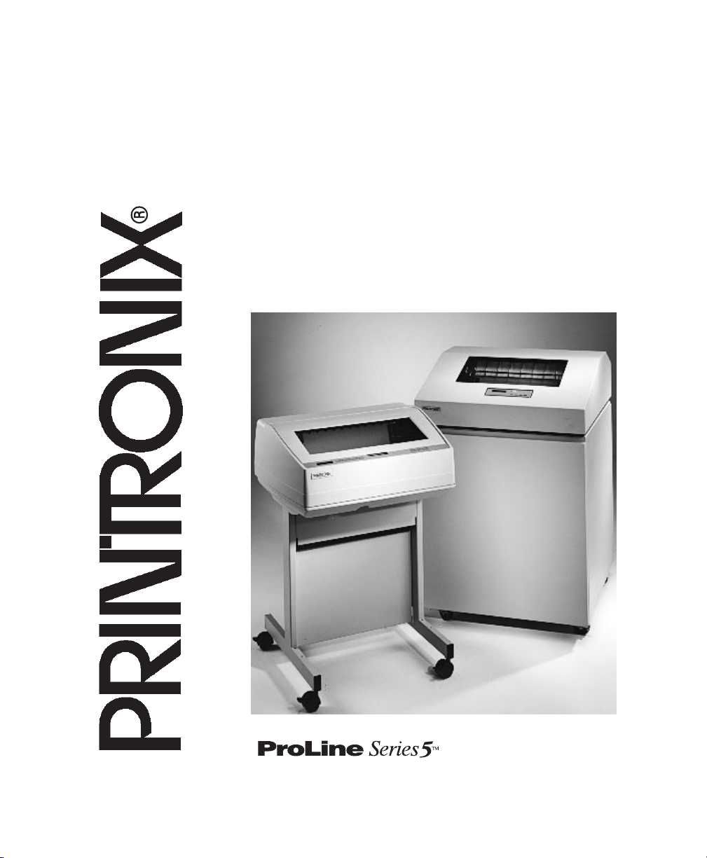
Printer Dimensions
Printer Cover
Cabinet Rear Door
27.0 in.
(68.6 cm)
29.0 in.
(73.7 cm)
83.0 in.
(210.8cm)
Cabinet
Model
27.0 in.
(68.6 cm)
27.0 in.
(68.6 cm)
41.0 in.
(104 cm)
57.5 in.
(146.1 cm)
25 in.
(63.5 cm.)
48.0 in.
(122 cm.)
24.6 in.
(62.48 cm.)
30 in.
(76.2 cm.)
Pedestal Model
57.5 in
(146.1 cm)
41.0 in
(104 cm)
27.0 in
(68.6 cm)
32.5 in
83.0 in
(210.8 cm)
(82.6 cm)
27.0 in
(68.6 cm)
27.0 in
(68.6 cm)
Cabinet Model with Stacker
2–4 Setting Up the Printer
Page 16

Printer Component Locations
Familiarize yourself with the names and locations of the printer components
shown in the following figures before continuing with the rest of the installation
procedure.
Spool
Ribbon
Horizontal
Adjustment Knob
Tractor
Lock
Paper Scale
Splined
Shaft
Paper Support
Ribbon Loading
Path Diagram
Tractor
Hammer
Bank Cover
and Ribbon
Mask
V
ertical Position
Knob
Forms Thickness
Lever
Setting Up the Printer 2–5
Page 17
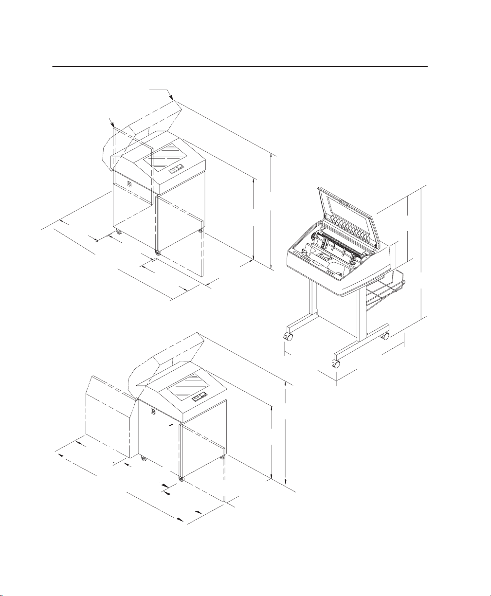
Unpacking the Printer
CAUTION
To avoid shipping damage, reinstall the shipping restraints whenever
you move or ship the printer.
Save the cardboard packing, foam blocks, and bubble wrap along with the other
packing materials, in case you need to move the printer later. If it is necessary to
move the printer, reinstall the shipping restraints, reversing the steps in this section.
Envelope
Cardboard
(2)
Packing
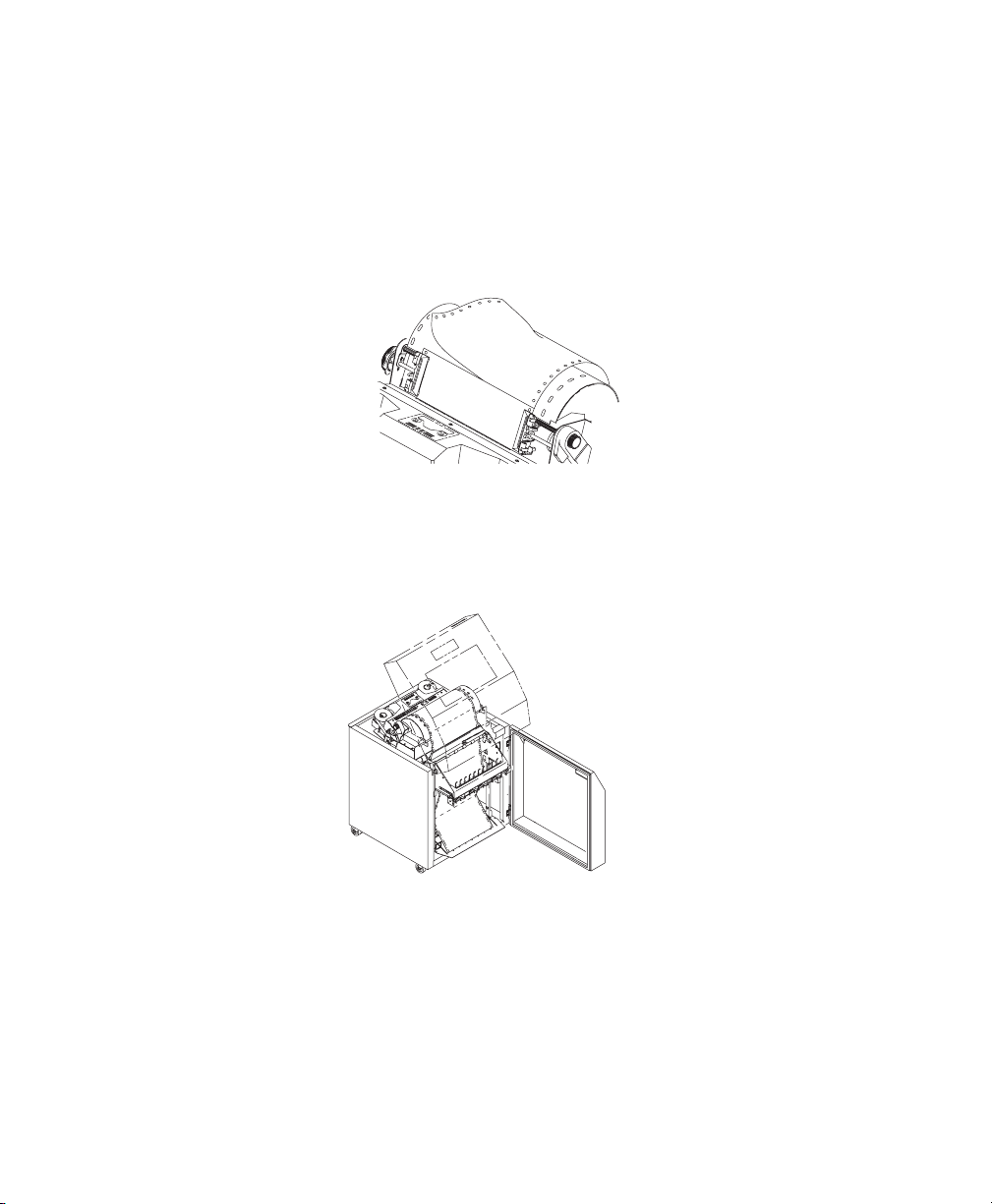
1. Raise the printer cover.
2. Remove the cardboard packing.
3. Open the tractor doors. Push the tractor locks down. Slide the tractors
outward as far as they will go. The forms thickness lever should be in the
fully open (raised) position.
4. Remove the envelope that contains the sample configuration printout. Store
this in the pouch that is attached to the left interior side of the cabinet.
2–6 Setting Up the Printer
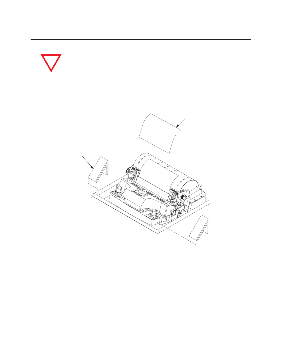
Page 18
Hammer
Bank
Protective Foam
Foam Strips (2)
5. Slide the paper supports outward as far as they will go. Lift the hammer bank
protective foam and remove it from between the ribbon mask and the platen.
6. Remove the foam strips and the tape securing the foam strips.
7. Rotate the forms thickness lever downward to position “A”.
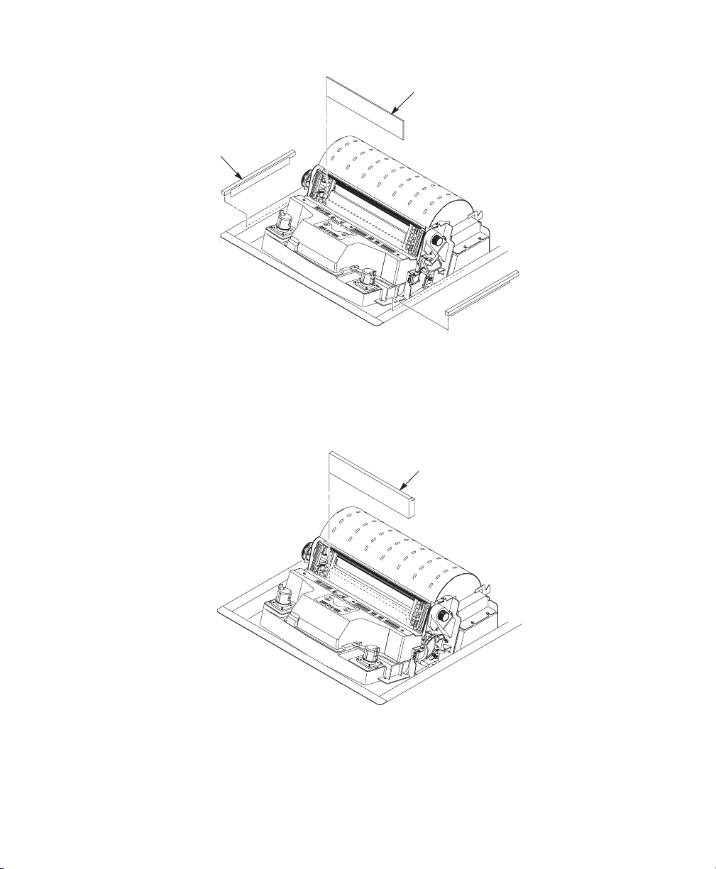
Platen
Protective
Foam
8. Rotate the platen protective foam toward the front of the printer and out from
under the support shaft.
Setting Up the Printer 2–7
Page 19
Adjusting Paper Supports
T
ractor Door
Paper
Supports
T
ractor Door
1. Slide the paper supports inward until they are approximately four inches from
the tractor door.
Release the Paper Chains (Cabinet Model)
T
ie W
rap
Tie Wrap
Paper Chains
Plastic Bags
1. Open the rear cabinet door.
2. Cut the tie wraps and release the paper chains from the bags at the top rear
of the printer frame. Remove the tie wraps and bags.
3. Make sure each chain hangs freely, with no kinks or knots.
2–8 Setting Up the Printer
Page 20
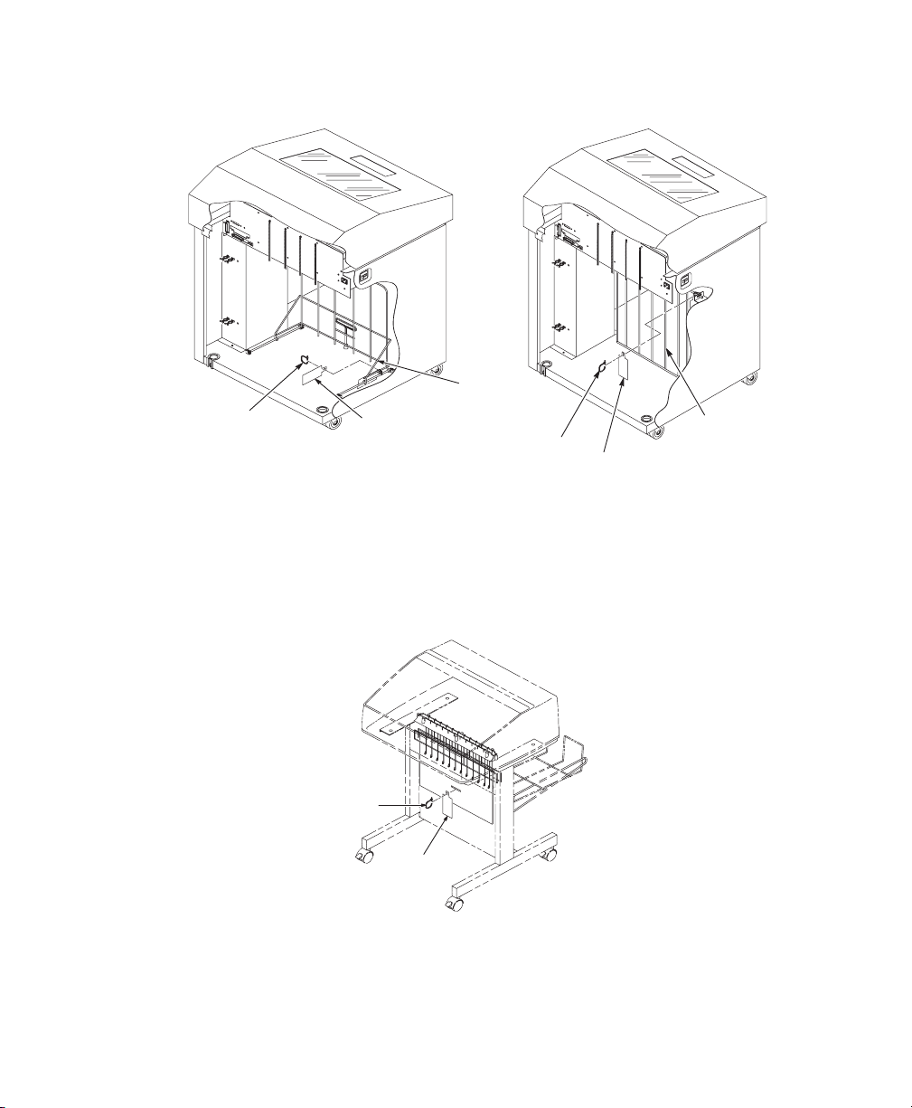
Removing Tags (Cabinet Model)
Passive
Paper
W
rap
Tie
800/900/1200/1400
Tag
Model
Stacker
T
ie W
rap
Tag
Fence
500 Model
1. Remove the tie wrap attached to the passive stacker paper fence, or if the
printer is equipped with a power stacker, the paper fence will be installed. It is
marked with a large, red tag.
2. Close the rear cabinet door.
Removing Tags (Pedestal Model)
Tie Wrap
Tag
Remove the tie wrap attached to the output basket. It is marked with a large, red
tag.
Setting Up the Printer 2–9
Page 21

Attach the Output Basket (Pedestal Model)
1. Place the output basket in the holes in the back of the printer.
2. Screw the ground wire attached to the output basket to the printer.
2–10 Setting Up the Printer
Page 22

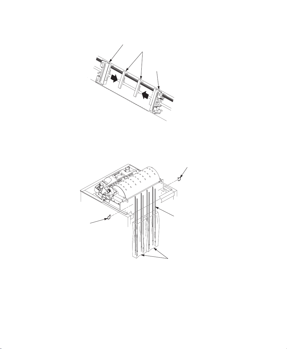
Remove the Shipping Restraints from the Power Stacker
This section only applies to printers with the power stacker installed.
Special packaging protects the power stacker mechanisms from damage during
shipment. This section describes how to remove the shipping restraints before
you operate the printer.
Save the packaging materials, since you may need to reinstall them.
If it is necessary to move the printer, reinstall the shipping restraints. Reverse the
steps in this section.
CAUTION
To avoid shipping damage, reinstall the shipping restraints
whenever you move or ship the printer.
Setting Up the Printer 2–11
Page 23
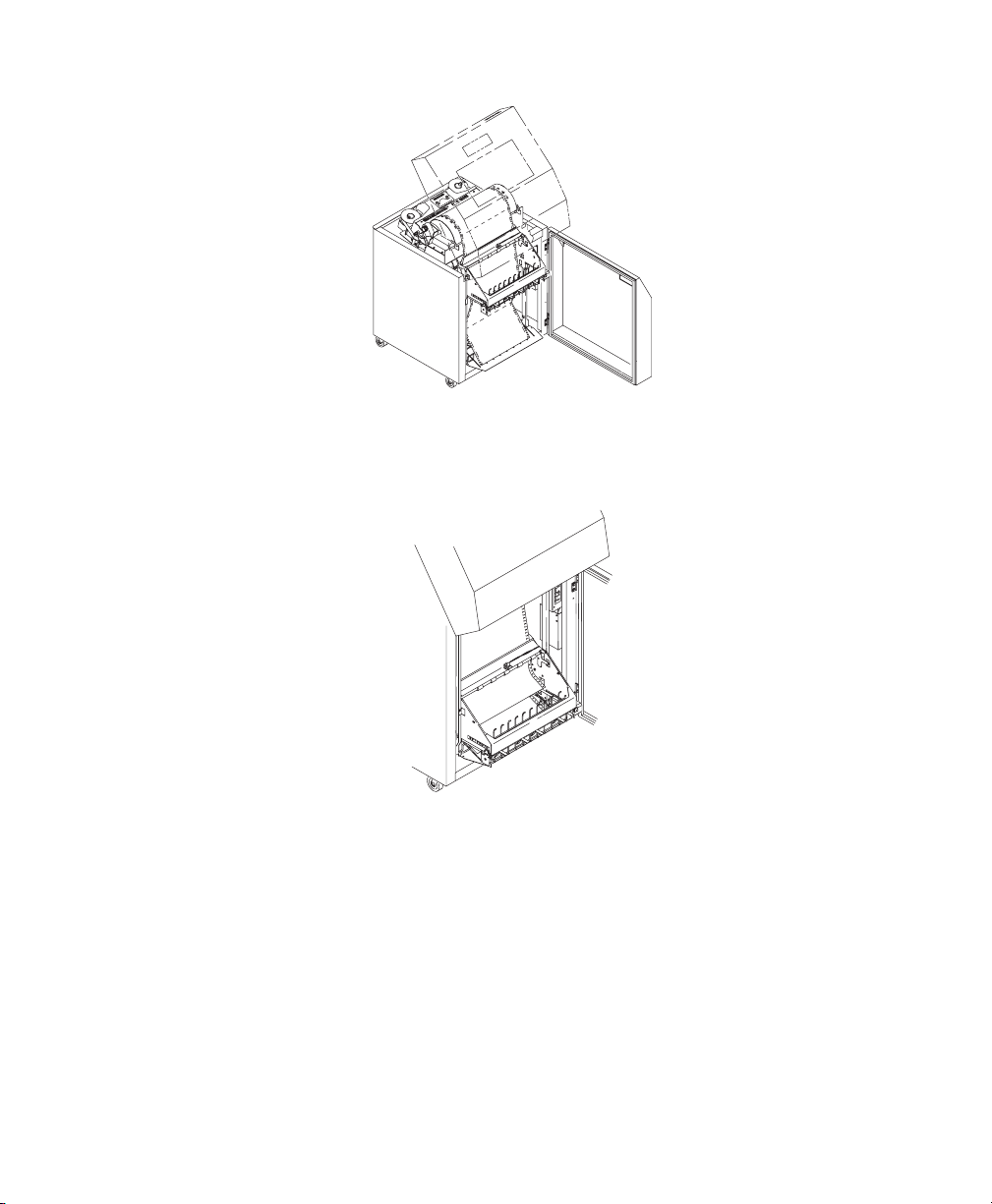
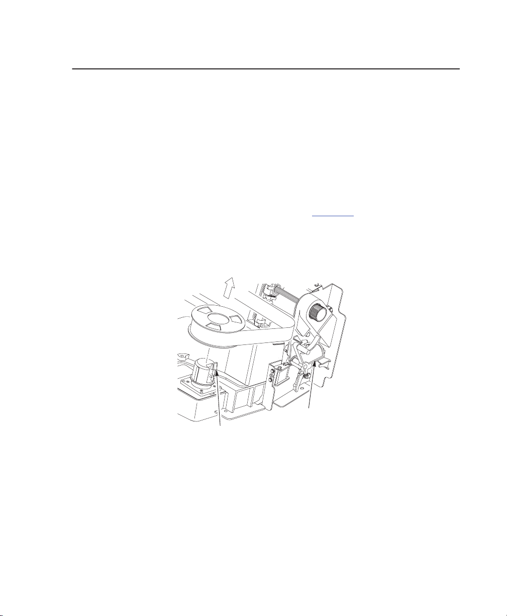
Removing Shipping Restraints from the Power Stacker
Paper Guide
Tie Wrap
T
ie W
rap
Bubble W
rap
1. Open rear door panel.
2. Remove tie wraps.
3. Raise the paper guide to its highest position by hand.
4. Remove bubble wrap from the paper tent.
2–12 Setting Up the Printer
Page 24
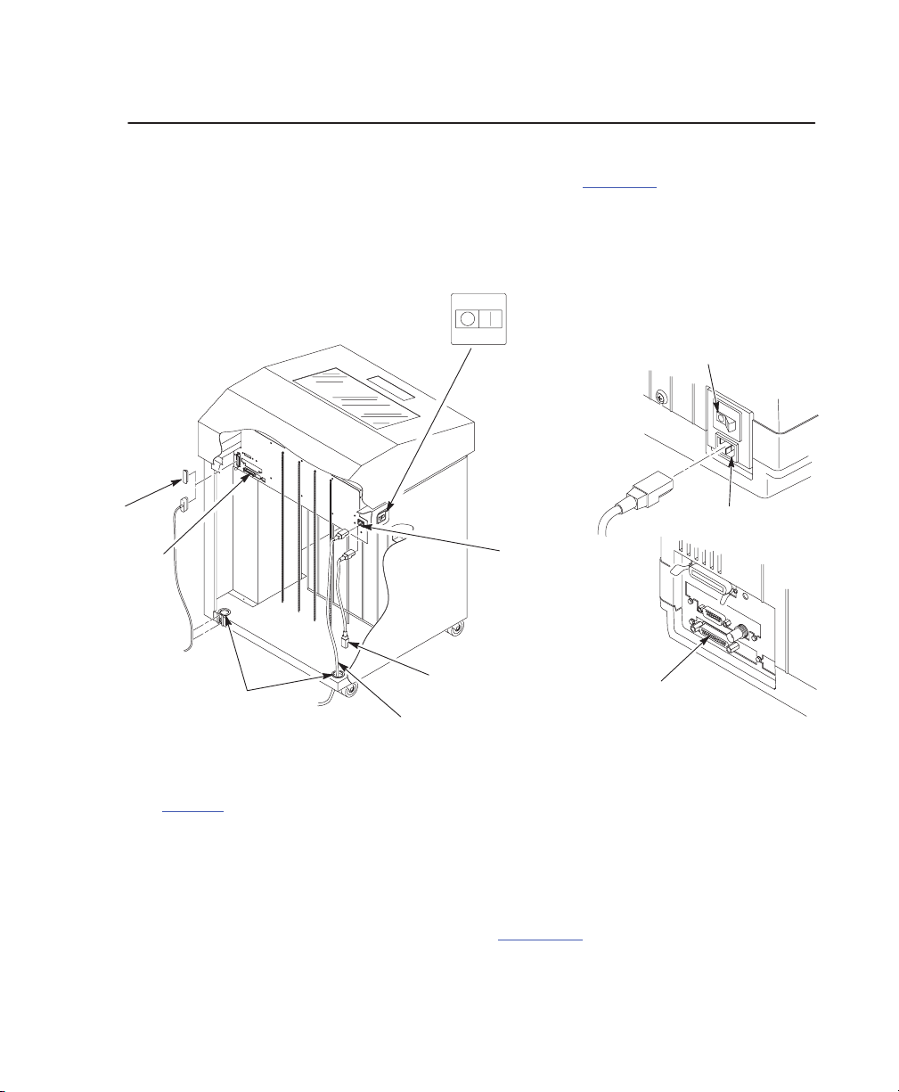
Connect the Interface and Power Cords
Before you connect the interface and power cables, verify the voltage source at
the printer site conforms to the requirements specified on page 2–3
. Make sure
the printer power switch is set to OFF.
Interface and Power Cord Connections
OFF
Cabinet
Model Pedestal Model
ON
Power Switch
I/O Cover
Host Interface
Connectors
1
See
1
Cable–Routing
Notches
page 2–16
AC Power Connection
(Stacker Units)
AC Power Cable
for illustrations of host interfaces available.
AC Power
Connector
(Standard Units)
Host Interface
Connectors
1
Figure 2–1. Interface and Power Locations
1. Make sure the printer power switch is set to O (Off).
2. Cabinet models only: Open the rear cabinet door, and remove the cover from
the I/O connector you have selected (See Figure 2–1
).
AC Power Connector
Setting Up the Printer 2–13
Page 25

3. Locate the notch in the lower left corner of the back of the cabinet (See
Figure 2–1).
4. Hold the I/O cable below its connector and gently push the cable through the
opening in the grommet seated in the notch (See Figure 2–1
).
5. Pull the cable up through the notch until it reaches the I/O plate. Attach the
cable connector to the printer interface connector previously selected in step
2 of this section. Secure the cable to the printer using the upper and lower
standoffs (See Figure 2–1
).
Box
Strap
6. Open the cabinet front door and cut the strap that secures the box, which
contains the power cord, printer ribbon, control panel overlay labels, and
documentation.
7. Open the box and remove the power cord, overlays, and documentation.
8. Guide the power cord up through the hole in the lower right back corner of
the cabinet. Thread the power cord inside the bracket where the gas spring is
attached (See Figure 2–1
).
9. Plug the power cord into the printer AC power connector, then into the AC
power outlet (See Figure 2–1
).
2–14 Setting Up the Printer
Page 26

Attach the Control Panel Overlays
1. Choose the overlay labels in the appropriate language.
2. Cabinet Models: Open the printer cover, peel off the protective backing, and
press the overlay into place.
3. Pedestal Models: Open the printer cover and insert overlay labels by sliding
them behind the control panel assembly in the appropriate place.
Overlay
Insert
Overlay
Pedestal Models
Insert Overlay
Overlay
Cabinet
Models
Setting Up the Printer 2–15
Page 27
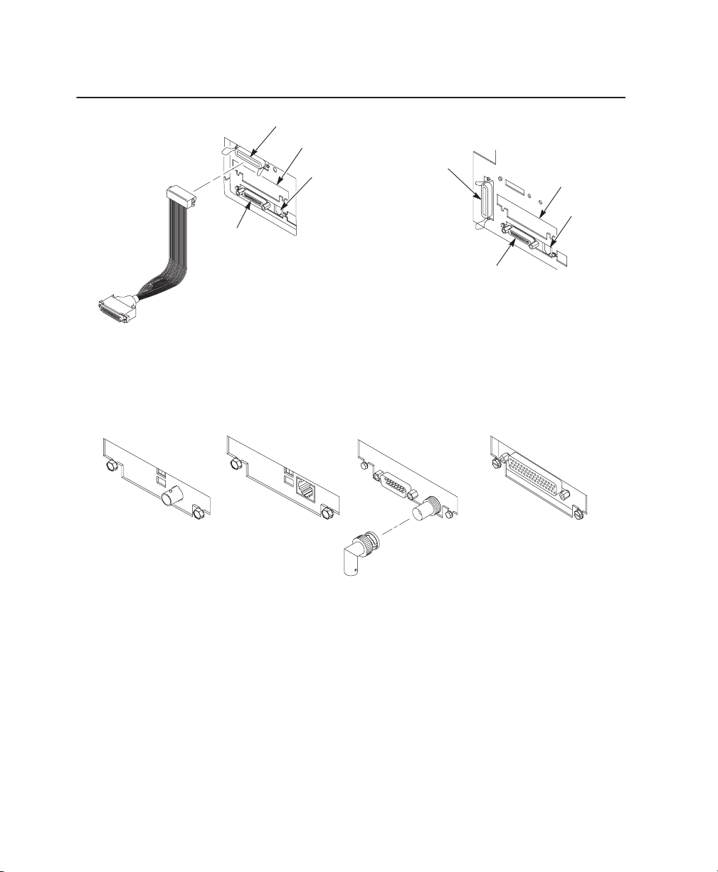
Interface Connections
Data
Products Standard Adapter
Centronics
Serial
RS232/RS422
Pedestal Model
Optional
1
Auxiliary I/O
Diagnostic
Centronics
Interfaces for Auxiliary I/O
1
Serial
RS232/RS422
Cabinet Model
Auxiliary
Diagnostic
I/O
Network 10Base2 Network 10BaseT
1 Not present on Network models
Coax / Twinax
90° BNC
connector required for Coax
connection with the Power Stacker
Data Products Longlines
.
1. Remove the cover from the I/O connector you have selected.
2. Attach the I/O cable connector to the printer interface connector.
2–16 Setting Up the Printer
Page 28

Install the Ribbon
1. Open the printer cover.
Tractor
Door
Forms
Thickness
Lever
Figure 2–2. Forms Thickness Lever
2. Raise the forms thickness lever as far as it will go.
3. Open the tractor doors.
Hammer Bank Cover
Hub
Latch
Ribbon Mask
Ribbon Guide
4. Squeeze the right hub latch and place the full spool on the right hub. Be sure
the ribbon feeds off the outside of the spool. Press the spool down until the
hub latch snaps into place.
Setting Up the Printer 2–17
Page 29
5. Thread the ribbon around the ribbon guide and along the ribbon path. Refer
to the ribbon path diagram on the shuttle cover. Be sure to thread the ribbon
between the hammer bank cover and the ribbon mask.
6. Place the empty spool on the left hub. Press the spool down until the hub
latch snaps into place. Turn the spool by hand to make sure the ribbon tracks
correctly in the ribbon path and ribbon guides.
2–18 Setting Up the Printer
Page 30
Load the Paper
When you start this procedure, verify that the printer cover is open, the forms
thickness lever is raised, and the tractor doors are open. (See Figure 2–2
EDGE OF
PAPER
BOX
1. For cabinet models, align the paper supply with the label on the floor. Make
sure that the paper pulls freely from the box.
.)
Paper
Slot is
8” below
printer base
Paper Slot
2. Feed the paper up through the paper slot. Hold the paper in place with one
hand (to prevent it from slipping down through the paper slot) while pulling it
through from above with your other hand.
Setting Up the Printer 2–19
Page 31

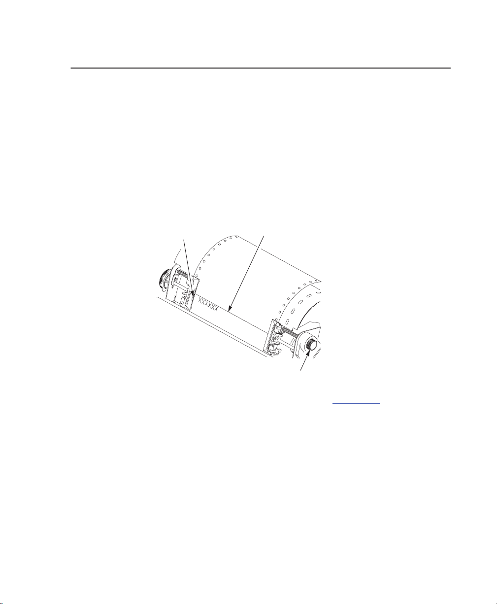
3. Pull the paper above and behind the ribbon mask, which is a silver metal
strip with a clear plastic edge protector. Load the paper on the left tractor
sprockets and close the tractor door.
T
ractor Door
Paper
Tractor
Lock
Paper Support
Ribbon Path
Diagram
CAUTION
To avoid damage to the printer caused by printing on the
platen, always position the left tractor unit directly to the
left of the “1” mark on the paper scale.
4. If adjustment is necessary, unlock the left tractor. Slide the tractor until it is
directly to the left of the number “1” on the paper scale and lock it. You can
also use the paper scale to count columns.
5. Unlock the right tractor.
2–20 Setting Up the Printer
Page 32

6. Load the paper onto the sprockets and close the tractor door. Make sure the
leading edge of the first sheet of paper is parallel to the tractor splined shaft.
If the paper is misaligned, reload it onto the tractor sprockets until its edge is
parallel to the splined shaft.
7. Slide the right tractor to remove paper slack or to adjust for various paper
widths. Lock the tractor.
Splined
Horizontal
Adjustment
Knob
Shaft
Paper Edge
Paper Scale
8. After both tractors are secured, you may use the horizontal adjustment knob
to make fine horizontal paper adjustments .
Setting Up the Printer 2–21
Page 33
Thin
A
B
C
Figure 2–3. Forms Thickness Lever
Paper
Medium Paper
Thick Paper
9. Lower the forms thickness lever. Set it to match the paper thickness.
(The A–B–C scale corresponds approximately to 1–, 3–, and 6–part paper
thickness.)
NOTE: Do not set the forms thickness lever too tightly; excessive friction
can cause paper jams, ribbon jams with potential for ribbon
damage, smeared ink, or wavy print.
10. For pedestal models, manually feed the paper through the rear paper exit by
using the vertical position knob.
11. Close the cabinet front door.
2–22 Setting Up the Printer
Page 34
Set the Top–of–Form
When you start this procedure, verify that the printer is in online mode, with the
printer cover open and the forms thickness lever lowered.
1. Set the power switch to I (On).
2. Press ON LINE to place the printer in offline mode. The LCD will then display
“OFFLINE / CONFIG. CONTROL.”
3. Press P
APER ADV
ANCE several times to ensure the paper feeds properly
beyond the tractors and over the lower paper path. Ensure the paper folds in
the same way in the stacking area as it does in the supply area.
TOF
Indicator
Perforation
V
ertical Position Knob
4. Raise the forms thickness lever as far as it will go. (See Figure 2–3.) This allows
you to turn the vertical position knob freely in order to align the top–of–form.
5. Locate the TOF indicator. It is the small tab located on both the right and left
tractor door.
6. Turn the vertical position knob to align the top of the first print line with the
TOF indicator.
7. Lower the forms thickness lever.
8. Press Set TOF.
Setting Up the Printer 2–23
Page 35
SureStaktPower Paper Stacker Option
Overview
This section explains how to set up and use the optional power paper stacker.
The power stacker mechanically directs the paper from the printer to the paper
stack.
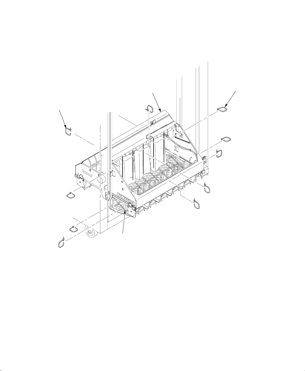
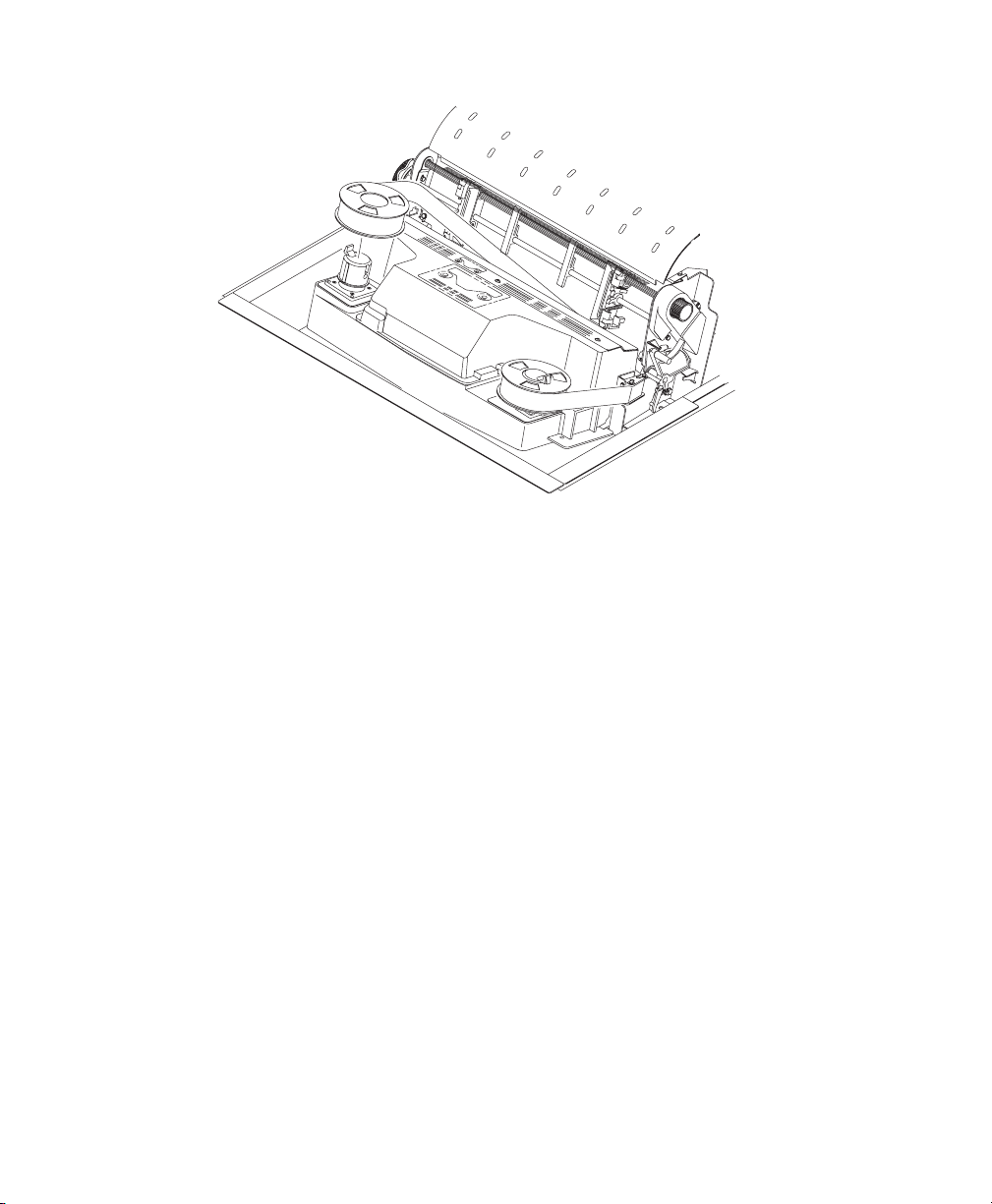
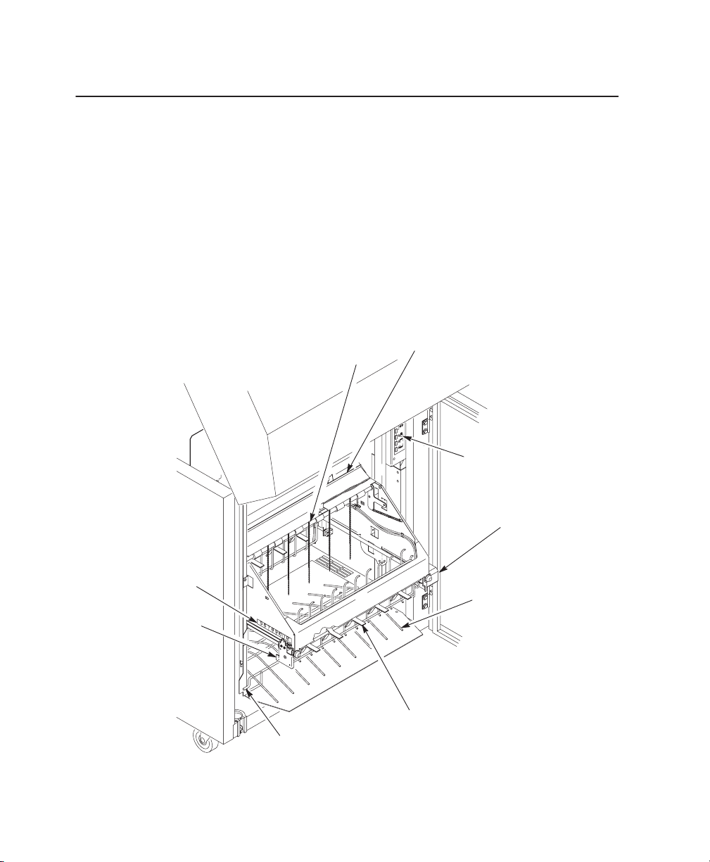
Power Paper Stacker Component Locations
Familiarize yourself with the names and locations of the components shown in
the following illustration before operating the paper stacker.
Paper Length
Indicator
Bearing Bracket
Alignment Rod (2)
Pinch
Rollers
Paper Throat
Paddle Shaft
Rear Control
Panel
Motor Bracket
Wire Paper T
(Optional)
ent
2–24 Setting Up the Printer
Page 36
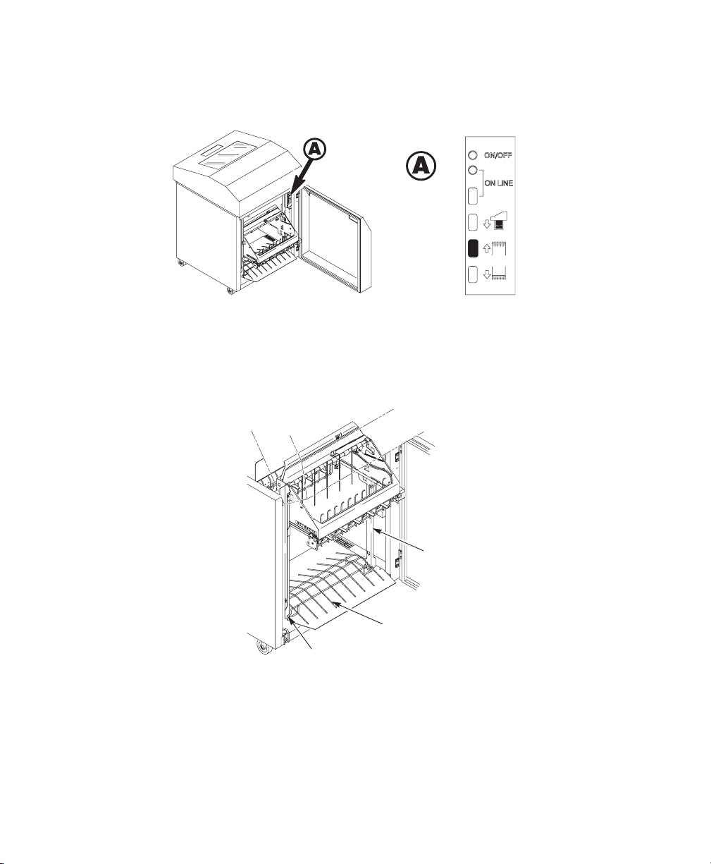
Setting Up the Power Paper Stacker
1. Turn the printer on.
2. Using the rear control panel, press ONLINE to take the printer offline. Press
STACKER UP button and wait for the stacker to reach the top of its travel.
Rails
Wire
Paper
T
ent (Optional)
Alignment
Rod (2)
3. Make sure the wire paper tent, if provided, is in the base of the stacker with
the alignment rods against the paper stacker rails.
Setting Up the Printer 2–25
Page 37
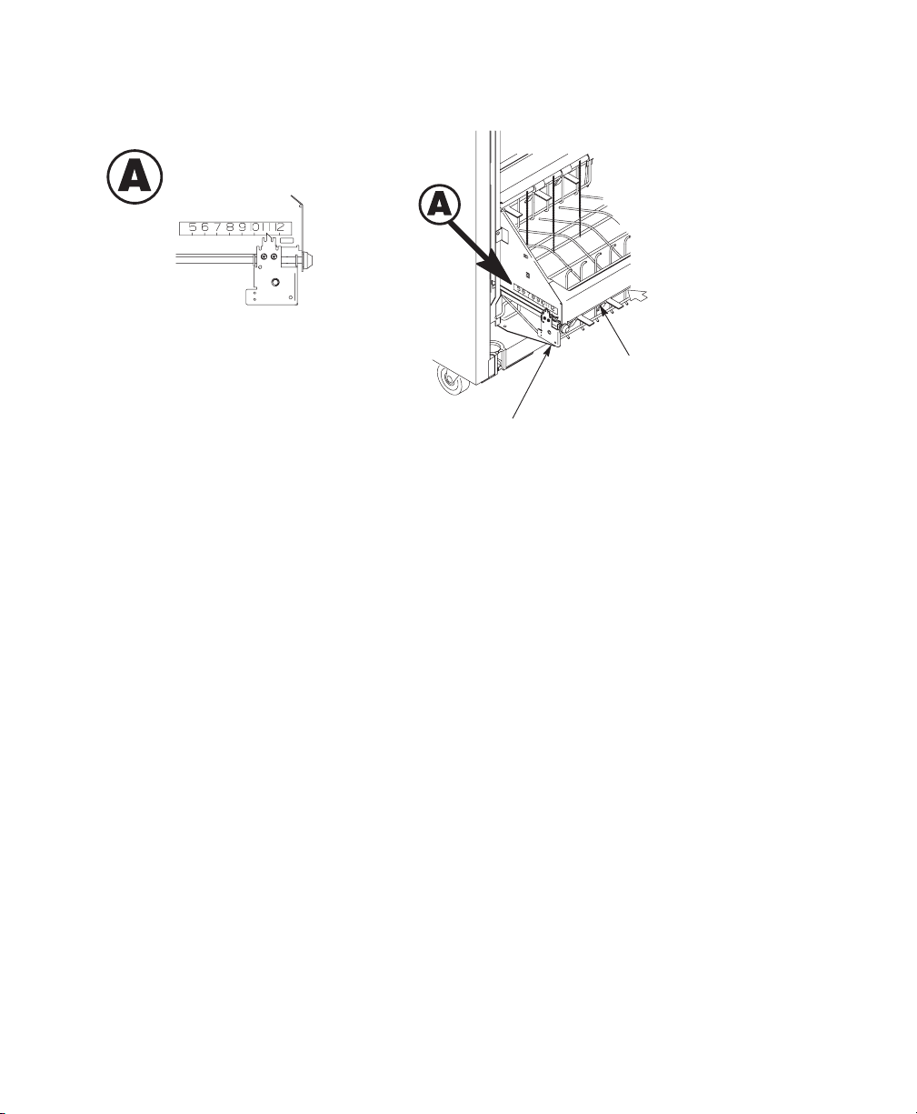
Paddle Shaft
Bearing
Bracket
4. Set the desired paper length (5–12 inch range), as follows:
Grasping the paddle shaft, push or pull toward the front or the rear of the printer,
setting the desired paper length by aligning indicator notch on the bearing
bracket with the paper length indicator.
5. Continue with the Loading and Starting the Power Stacker section.
Loading and Starting the Power Stacker
1. Using the rear control panel, press the P
the paper in the paper throat. Continue to advance paper until paper reaches
the wire tent and there is an excess of 3–5 pages in the stacker. Be certain
the paper passes through paper stacker throat.
APER ADV
ANCE key and hand feed
2–26 Setting Up the Printer
Page 38
2. Stack the 3–5 sheets of paper on top of the wire paper tent, making sure the
paper lies with the natural fold.
3. Press the ON LINE key, from either the front or rear panel, to put the printer
in the online state. The stacker frame then returns to its proper position for
printing.
4. Check that the paper is still centered between the paper guides
5. Close the rear cabinet door.
6. You are now ready to print.
Setting Up the Printer 2–27
Page 39
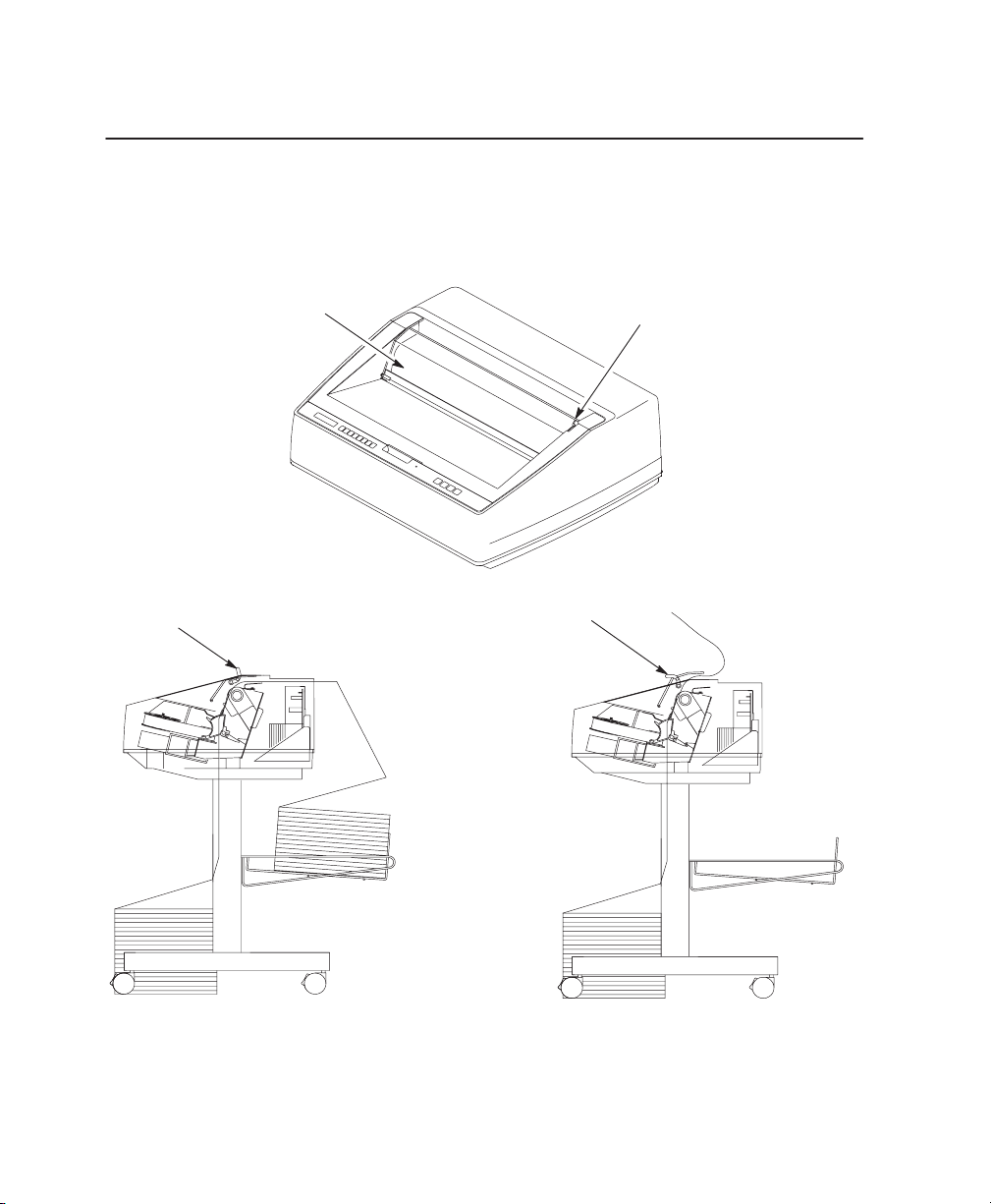
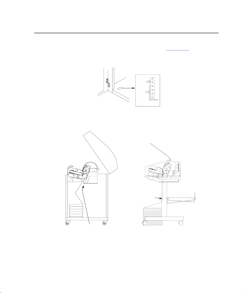
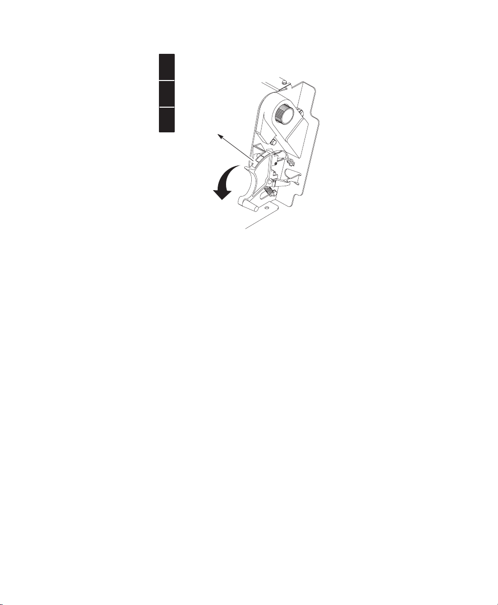
Quick Access Cover (Pedestal Model Only)
If your pedestal printer is equipped with the quick access cover, you may choose
how the paper exits the printer. Pressing the lever up on the quick access cover
allows the paper to exit the rear of the printer like a regular pedestal model. Pushing
the lever down allows the paper to exit the top of the printer for demand printing.
Quick Access Cover
Lever (up position)
Lever
Lever (down position)
2–28 Setting Up the Printer
Page 40

3
Operating the Printer
Powering On the Printer 3–2.
Operating Modes 3–2.
The Control Panels 3–3.
Control Panel Functionality 3–4.
Reloading Paper 3–8.
Unloading Paper from the Power Paper Stacker 3–11.
Replacing Ribbon 3–13.
. . . . . . . . . . . . . . . . . . . . . . . . . . . . . . . . . . . . . . . . . . .
. . . . . . . . . . . . . . . . . . . . . . . . . . . . . . . . . . . . . . . . . . . . . . . . .
. . . . . . . . . . . . . . . . . . . . . . . . . . . . . . . . . . . . . . . . . . . . . . .
. . . . . . . . . . . . . . . . . . . . . . . . . . . . . . . . . . . . . . . .
. . . . . . . . . . . . . . . . . . . . . . . . . . . . . . . . . . . . . . . . . . . . . . . . .
. . . . . . . . . . . . . . . . . . . . . . . . . . . . . . . . . . . . . . . . . . . . . . . .
. . . . . . . . . . . . . . . . . . . . . .
Operating the Printer 3–1
Page 41

Powering On the Printer
When you power on the printer, the printer executes a self-test. The default power–up
state is online. When the self–test completes and the software has initialized
successfully, the status indicator lights indicate the printer is online and the default
value of the type of emulation you have installed appears in the display.
If there is a fault during the self-test, the status indicator flashes and a specific
fault message appears on the display (such as “LOAD PAPER”). The alarm also
sounds if it is configured to do so.
Operating Modes
Online — In online mode, the printer can receive and print data sent from the
host. Pressing the ON LINE key toggles the printer from offline to online mode.
The status indicator is lit in online mode.
Offline — In offline mode, you may perform operator functions, such as loading
paper and setting top-of-form. You may also move within the printer configuration
menus. Pressing the ON LINE key toggles the printer from online to offline mode.
The status indicator is off in offline mode.
Fault — In fault mode, a fault condition exists that must be cleared before
printing can continue. The status indicator flashes, the alarm beeps (if configured
to sound), and a descriptive fault message displays.
The current operating mode may be selected via control panel keys, or may
result from routine operations such as powering on the printer.
3–2 Operating the Printer
Page 42

Using the Control Panels
Format Conventions
Messages, keys, and indicators, are shown as they appear on the control panel.
Key combinations are indicated with the plus (+) sign. For example, “Press
Y+B” means to press the Y key and the B key at the same time.
UP
PREV NEXT
DOWN
Message
SET
T
OF
T CONFIG
PR
JOB SELECT
ENTER
PREV NEXT
Display
Message Display
Cabinet
Model
Status Indicator
ONLINE
CLEAR
PAPER
ADVANCE
CANCELVIEW
EJECT
Status Indicator
JOB
SET
TOF
SELECT
PRT
CONFIG
ENTER
DOWN
UP
ONLINE
CLEAR
VIEW
EJECT
ADVANCE
CANCELPAPER
Pedestal Model
Operating the Printer 3–3
Page 43

Control Panel Keys
ON LINE / CLEAR – Toggles the printer between online and offline modes. If a
fault condition exists, pressing this key will clear a fault message and return the
printer from fault mode to offline mode.
NOTE: If the fault condition is not corrected
message will reappear when attempting to place the printer online.
P
APER ADV
how long the key is pressed. Quickly pressing this key will perform a line feed.
Holding the key down for more than one half second will advance the paper to
Top–of–Form. In online mode, only an advance to Top–of–Form will occur.
• If there is data in the printer buffer, the data will print and then the paper
• In the fault state P
VIEW / EJECT
key is pressed. When the VIEW/EJECT key is pressed quickly the view function
is executed. When it is held down for longer than 1/2 second, the eject function is
executed.
View Function – Press and release VIEW/EJECT to move the last data printed
to the tractor area for viewing. While in the view state, the Y or B can be
pressed to adjust the paper up or down in 1/72 inch increments. Press
VIEW/EJECT a second time to move back to the adjusted print position.
ANCE – Performs advance to top of form or line feed, depending on
will move to the next top–of–form.
APER ADV
next top–of–form; instead, it will slew the paper 11 inches.
– Executes the view or eject function, depending on how long the
ANCE does not advance the paper to the
before
pressing this key, the fault
Eject Function – In offline mode, when the Eject Mode is enabled, holding the
VIEW/EJECT key down for longer than one half second will invoke the Eject
function. The amount of paper advanced is determined by the eject mode
selected in the configuration menu: standard, simple tear, and form saver action.
See Appendix B for details.
3–4 Operating the Printer
Page 44

NOTE: Pressing ON LINE also moves the paper back to the adjusted print
position and returns the printer to online. If you press PAPER
ADVANCE while in view or eject mode, the paper will return to the
adjusted print position and then perform the paper advance motion.
Standard Mode – The first press ejects the paper 22 inches. Pressing the key
again retracts 22 inches.
Simple Tear Mode – Allows demand printing for specially designed forms.
Form Saver Mode – Allows near demand printing of forms that do not have
pre–printed headers.
CANCEL – In offline mode, this key cancels all data in the print buffer (if enabled
in the “MAINT/MISC” menu). The print buffer is cleared without printing any of
the data and the current paper position is set as the Top–of–Form. If this function
is disabled, the CANCEL key will be ignored.
NOTE: Use of this key will cause loss of data
SET TOF (Top–of–Form) – Sets the top–of–form on the printer. This key is active
only when the printer is offline and will not operate if the printer is in a fault
condition. The paper moves down to the print position and aligns to the
top–of–form.
NOTE: If there is any data in the buffer, the paper will move to the last print
position.
PRT CONFIG – In offline mode, prints the current printer configuration. This key
requires a confirmation with the ENTER key; pressing any other key will exit from
this function.
JOB SELECT – In the offline mode, press JOB SELECT. The display reads
“Load Config ” and the name or number of the currently loaded configuration.
Press JOB SELECT until the configuration you want to load displays. Press
ENTER and “Loading Saved Configuration” displays. The configuration is loaded
into memory. Press ON LINE twice to return to online mode.
.
Operating the Printer 3–5
Page 45

ENTER – Selects the currently displayed option value as the active value. When
the display shows the desired configuration value, press and release to select
that value as the active value. An asterisk (*) appears next to the active value on
the display. ENTER also starts and stops printer tests and generates a
configuration printout. Press ENTER to start a printer test or configuration
printout. Press again to stop the printer test.
NOTE: The ENTER key must be unlocked in order to function.
UP or DOWN
(
Y or B ) – Moves up and down between levels in the
configuration menus and makes vertical forms adjustment. After pressing VIEW,
press Y or B to adjust the paper up or down in 1/72 inch increments for fine
vertical forms alignment.
UP + DOWN (
Y + B ) – Locks and unlocks the ENTER key.
NOTE: The ENTER key lock and unlock function can be configured to be
other than Y+B (See page 4–93).
PREV or NEXT
configuration menu. In the configuration menu. press
(
A
or " ) – Moves between the options on the current level of
A
to scroll backward or
press " to scroll forward through the menu selections on the same level.
PREV + NEXT
(
A
+ " ) When both keys are pressed simultaneously, the printer
will reset to the power–up configuration and reset its internal state.
Y + ON LINE (IPDS Emulation Only)
In offline mode, press Y + ON LINE. If there is data in the IPDS printer buffer,
the printer will be placed in online mode, print one page, and return to the offline
mode. This action can be repeated until the end of a print job. Each time it prints
only one page. If no data are in the IPDS printer buffer, the printer will be placed
in online mode.
In the fault state, Y + ON LINE does not work.
3–6 Operating the Printer
Page 46

Y + P
APER ADV
ANCE (IPDS Emulation Only)
In offline mode, press Y + P
ANCE key
ADV
press both, the printer will move to the previous top–of–form position. If there is
IPDS data in the printer buffer, it will not print the data.
In the fault state, Y + P
+ VIEW (IPDS Emulation Only)
Y
In offline mode, press Y
printer will be placed in online mode, print one line, and return to offline mode.
This action can be repeated until the end of the job. This function prints only one
line of text. If the data is not text, only 1/6 inch prints. If no data is in the IPDS
printer buffer, the printer will be placed in online mode for one second and then
return to offline mode. If there is no data in the buffer, the printer will go online
and remain online until a job is released, it then returns to offline mode.
In the fault state, Y + VIEW does not work.
, the printer will perform a reverse linefeed. If you continue to
APER
APER ADV
+ VIEW
. If there is data in the IPDS printer buffer, the
ADVANCE. If you release the PAPER
ANCE does not work.
Operating the Printer 3–7
Page 47

Reloading Paper
Follow this procedure when “LOAD PAPER” displays. (This message occurs
when the last sheet of paper passes through the paper slot.) This procedure
reloads paper without removing the last sheet of the old paper supply. This action
retains the current top of form setting.
Thin
A
B
C
1. Raise the printer cover. Raise the forms thickness lever as far as it will go.
Press CLEAR to turn off the alarm. Do not open the tractor doors or remove
the existing paper.
Paper
Medium Paper
Thick Paper
Figure 3–1. Forms Thickness Lever
2. Open the cabinet front door. Align the paper supply with the label on the
floor. Ensure that the paper pulls freely from the box.
3–8 Operating the Printer
Page 48
Paper
Slot
Figure 3–2. Paper Slot Location
3. Locate the paper slot inside the cabinet and feed the paper up through the slot. It
may be easier to feed one corner of the new paper up through the slot first.
When this corner can be grasped from the top, rotate the paper back to the
normal position. If necessary, gently press the existing paper back.
NOTE: If you are unable to load the new paper over the existing paper in
step 3, this procedure will not work. Unload paper completely
perform the normal load paper procedure on page 2–19
.
4. Hold the paper to prevent it from slipping down and through the paper slot.
5. Pull the new paper above and behind the ribbon mask, but in front of the
existing paper. The ribbon mask location is shown on the ribbon path
diagram. If necessary, gently press the existing paper back.
6. Align the top edge of the new paper with the top perforation of the existing paper.
Operating the Printer 3–9
Page 49

Existing Paper
Existing
Perforation
Ribbon Path
Diagram
New
Paper
7. Load the new paper over the existing paper.
Open and load the tractors one at a time to prevent the paper from slipping.
NOTE: Make sure that the top edge of the new paper lines up with the top
horizontal perforation of the last page.
8. Lower the forms thickness lever.
9.
Press CLEAR
to clear the “LOAD PAPER” fault message from the display.
10. Press ON LINE
to place the printer in online mode and resume printing.
11. Make sure the paper stacks properly.
12. On cabinet models: Open the cabinet rear door. Make sure the paper is aligned
with the label in the output area (inside the cabinet). Close the front and rear
doors.
13. Perform the following steps to test the printer:
a. Make sure that the printer top cover is open and the forms thickness
lever is lowered.
b. Press ON LINE. (The printer must first be offline to test the printer.)
c. Press UP + DOWN (
Press PREV (
d.
Y + B ) (Allows configuration changes).
A ) until OFFLINE “DIAGNOSTICS” appears on the
display.
e. Press DOWN (
B ) until DIAGNOSTICS “Printer Tests” appears on the
display.
3–10 Operating the Printer
Page 50
f. Press DOWN (
B ) until Printer Tests “Shift Recycle” appears on the display.
g. To start test, press ENTER.
h. To stop test, press ENTER.
i. Press UP + DOWN (
Y + B ) until ENTER SWITCH “LOCKED” appears
on the display.
j. Examine the print quality. The characters should be fully formed and of
uniform density.
k. If the print quality is good, close the printer cover; press ON LINE to
enable printing.
NOTE: The ENTER key lock and unlock function can be configured to be
other than Y+B (See page 4–93
).
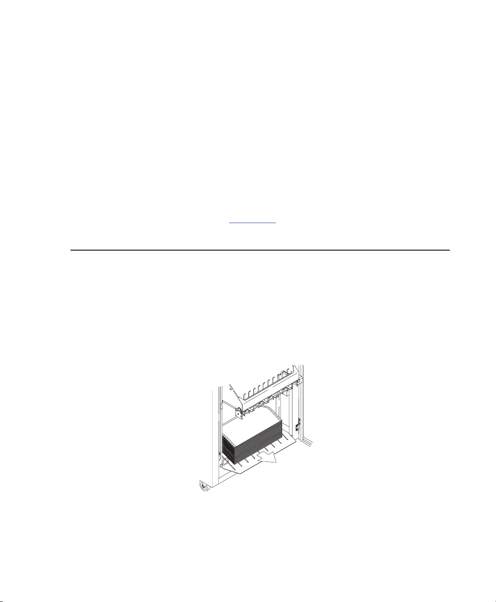
Unloading Paper from the Power Stacker
Removing Paper from the Printer:
1. Unload paper from the print mechanism.
2. Open the rear cabinet door.
3. Using the rear control panel, press ST
ACKER UP
and wait for the stacker to
reach the top of its travel.
4. Remove the paper from the rear of the printer.
5. Close the rear cabinet door.
Operating the Printer 3–11
Page 51
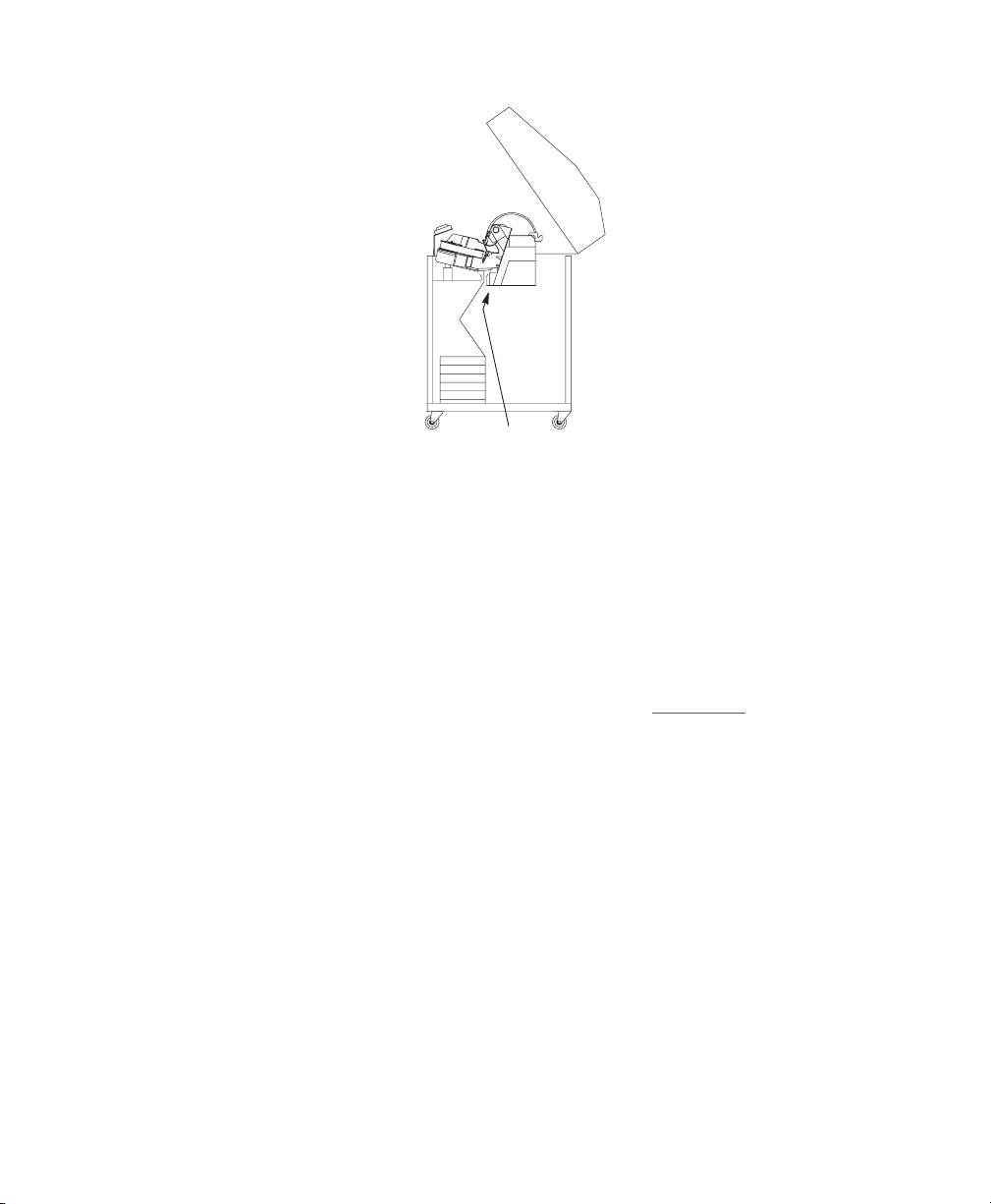
Removing Paper from the Power Stacker Only:
1. Open the rear cabinet door.
2. Using the rear control panel, press ON LINE to take the printer offline
3. Press STACKER UP and wait for the stacker to reach the top of its travel.
4. Open the printer lid.
5. Tear the paper off at the first perforation above the tractors and let the paper
fall back through the open power stacker throat.
6. From the rear of the printer, making sure the paper lies with its natural folds,
lay the paper on top of the paper stack.
7. Remove the paper from the rear of the printer.
8. Close the rear door and the top cover.
3–12 Operating the Printer
Page 52
Replacing the Ribbon
1. Press ON LINE to place the printer in offline mode.
2. Open the printer cover
3. Remove the old ribbon:
a. Raise the forms thickness lever as far as it will go.
b. Press in on the hub latches and lift the ribbon spools off the hubs. Lift the
ribbon out of the ribbon path.
4. Discard the old ribbon.
5. If necessary, clean the interior of the printer. (See page 6–2
6. Install the new ribbon:
a. With the ribbon to the outside, place the full spool on the right hub. Press
down on the spool until the hub latch snaps in place.
Forms
Thickness
Hub Latch
Lever
b. Thread the ribbon around the ribbon guide and along the ribbon path.
Refer to the ribbon path diagram on the shuttle cover.
c. Place the empty spool on the left hub. Press down on the spool until
the hub latch snaps into place. Hand turn the right spool to make sure
the ribbon tracks correctly in the path and ribbon guides.
.)
Operating the Printer 3–13
Page 53

7. Lower the forms thickness lever. Set it to match the paper thickness you are
using.
(See Figure 3–1.)
8. Close the printer cover.
9. Press ON LINE to return the printer to online mode.
3–14 Operating the Printer
Page 54

4
The Configuration Menus
Navigating the Menus 4–11.
Configuration Main Menu 4–13.
CONFIG. CONTROL Menu 4–15.
Load Config. 4–15.
Save Config. 4–15.
Print Config. 4–15.
Delete Config. 4–15.
Power–Up Config. 4–15.
Protect Configs. 4–16.
Name Configs. 4–16.
Reset Cfg Name 4–16.
ACTIVE IGP EMUL Menu 4–17.
IGP Configurations – PGL 4–18.
Configuring the Emulations with the Control Panel 4–19.
The IGP/PGL Emulation Submenu 4–20.
Define CR Code (Carriage Return) 4–20.
Define LF Code (Line Feed) 4–21.
Autowrap 4–21
Select SFCC 4–21.
PI Slew Range 4–21.
CR
Edit
Select Font 4–22.
Slash 0 4–22.
Select LPI 4–22.
Auto Uppercase 4–22.
Skip Command Prefix 4–22.
Power On IGP/PGL 4–23.
Extended Execute Copy 4–23.
. . . . . . . . . . . . . . . . . . . . . . . . . . . . . . . . . . . . . . . . . . . . . . . . . . . . .
. . . . . . . . . . . . . . . . . . . . . . . . . . . . . . . . . . . . . . . . . . . . . . . . . . . . .
. . . . . . . . . . . . . . . . . . . . . . . . . . . . . . . . . . . . . . . . . . . . . . . . . . . . .
. . . . . . . . . . . . . . . . . . . . . . . . . . . . . . . . . . . . . . . . . . . . .
. . . . . . . . . . . . . . . . . . . . . . . . . . . . . . . . . . . . . . . . . .
. . . . . . . . . . . . . . . . . . . . . . . . . . . . . . . . . . . . . . . .
. . . . . . . . . . . . . . . . . . . . . . . . . . . . . . . . . . . . . . . . . . . . . . . . .
. . . . . . . . . . . . . . . . . . . . . . . . . . . . . . . . . . . . . . . . . . . . . . . . .
. . . . . . . . . . . . . . . . . . . . . . . . . . . . . . . . . . . . . . . . . . . . . . . . .
. . . . . . . . . . . . . . . . . . . . . . . . . . . . . . . . . . . . . . . . . . . . . . .
. . . . . . . . . . . . . . . . . . . . . . . . . . . . . . . . . . . . . . . . . . . .
. . . . . . . . . . . . . . . . . . . . . . . . . . . . . . . . . . . . . . . . . . . . . .
. . . . . . . . . . . . . . . . . . . . . . . . . . . . . . . . . . . . . . . . . . . . . . .
. . . . . . . . . . . . . . . . . . . . . . . . . . . . . . . . . . . . . . . . . . . . .
. . . . . . . . . . . . . . . . . . . . . . . . . . . . . . . . . . . . . . . . .
. . . . . . . . . . . . . . . . . . . . . . . . . . . . . . . . . . . . . . . . .
. . . . . . . . . . . . . . . . . . . .
. . . . . . . . . . . . . . . . . . . . . . . . . . . . . . . . .
. . . . . . . . . . . . . . . . . . . . . . . . . . . . .
. . . . . . . . . . . . . . . . . . . . . . . . . . . . . . . . . . .
. . . . . . . . . . . . . . . . . . . . . . . . . . . . . . . . . . . . . . . . . . . . . . . . .
. . . . . . . . . . . . . . . . . . . . . . . . . . . . . . . . . . . . . . . . . . . . . . .
. . . . . . . . . . . . . . . . . . . . . . . . . . . . . . . . . . . . . . . . . . . . . . . . . .
. . . . . . . . . . . . . . . . . . . . . . . . . . . . . . . . . . . . . . . . . . . . . . . . . . .
. . . . . . . . . . . . . . . . . . . . . . . . . . . . . . . . . . . . . . . . . . . . . .
. . . . . . . . . . . . . . . . . . . . . . . . . . . . . . . . . . . . . . . . .
. . . . . . . . . . . . . . . . . . . . . . . . . . . . . . . . . . . . . . . . . . .
. . . . . . . . . . . . . . . . . . . . . . . . . . . . . . . . . . . . . . .
4–22.
Configuration Menus 4–1
Page 55

UPC Descenders 4–23.
Compressed
Ignore Character 4–24.
Ignore Mode 4–24.
Select Character 4–24.
Compatibility Mode 4–24.
Expanded Font 4–24.
Optimized Ratio 4–25.
Interleaved 2/5 Selection 4–25.
True Form Slew 4–25.
Printer PI Line 4–25.
IGP/PGL Character Set Menu 4–26.
IGP Configurations – VGL 4–27.
Configuring the Emulation with the Control Panel 4–29.
The IGP/VGL Emulation Submenu 4–30.
SFCC & Pwrup 4–30.
Power Up^X 4–31.
Power Up^F 4–31.
Power Up^PY 4–31.
LPI 4–31
. . . . . . . . . . . . . . . . . . . . . . . . . . . . . . . . . . . . . . . . . . . . . . . . . . . . . . . . . .
Graphics Options 4–31.
Error Handling 4–34.
Ignore/DB8 Setup 4–35.
Font Set 4–36.
PI Control 4–37.
Prt to Emulate 4–37.
IGP/VGL Character Set Menu 4–38.
EMULATION Menu. 4–39.
. . . . . . . . . . . . . . . . . . . . . . . . . . . . . . . . . . . . . . . . . . . . . . . . . . . . .
. . . . . . . . . . . . . . . . . . . . . . . . . . . . . . . . . . . . . . . . . . . . . . . . . . .
. . . . . . . . . . . . . . . . . . . . . . . . . . . . . . . . . . . . . . . . . . . . .
CPI
. . . . . . . . . . . . . . . . . . . . . . . . . . . . . . . . . . . . . . . . . . . . .
. . . . . . . . . . . . . . . . . . . . . . . . . . . . . . . . . . . . . . . . . . . . .
. . . . . . . . . . . . . . . . . . . . . . . . . . . . . . . . . . . . . . . . . . . . . . . . .
. . . . . . . . . . . . . . . . . . . . . . . . . . . . . . . . . . . . . . . . . . . . .
. . . . . . . . . . . . . . . . . . . . . . . . . . . . . . . . . . . . . . . . . . .
. . . . . . . . . . . . . . . . . . . . . . . . . . . . . . . . . . . . . . . . . . . . . .
. . . . . . . . . . . . . . . . . . . . . . . . . . . . . . . . . . . . . . . . . . . . . .
. . . . . . . . . . . . . . . . . . . . . . . . . . . . . . . . . . . . . .
. . . . . . . . . . . . . . . . . . . . . . . . . . . . . . . . . . . . . . . . . . . . . .
. . . . . . . . . . . . . . . . . . . . . . . . . . . . . . . . . . . . . . . . . . . . . . .
. . . . . . . . . . . . . . . . . . . . . . . . . . . . . . . . . .
. . . . . . . . . . . . . . . . . . . . . . . . . . . . . . . . . . . . . . . . .
. . . . . . . . . . . . . . . . . . . . .
. . . . . . . . . . . . . . . . . . . . . . . . . . . . . . . . .
. . . . . . . . . . . . . . . . . . . . . . . . . . . . . . . . . . . . . . . . . . . . . . .
. . . . . . . . . . . . . . . . . . . . . . . . . . . . . . . . . . . . . . . . . . . . . . . . .
. . . . . . . . . . . . . . . . . . . . . . . . . . . . . . . . . . . . . . . . . . . . . . . . .
. . . . . . . . . . . . . . . . . . . . . . . . . . . . . . . . . . . . . . . . . . . . . . . .
. . . . . . . . . . . . . . . . . . . . . . . . . . . . . . . . . . . . . . . . . . . . .
. . . . . . . . . . . . . . . . . . . . . . . . . . . . . . . . . . . . . . . . . . . . . . .
. . . . . . . . . . . . . . . . . . . . . . . . . . . . . . . . . . . . . . . . . . . .
. . . . . . . . . . . . . . . . . . . . . . . . . . . . . . . . . . . . . . . . . . . . . . .
. . . . . . . . . . . . . . . . . . . . . . . . . . . . . . . . . .
. . . . . . . . . . . . . . . . . . . . . . . . . . . . . . . . . . . . . . . . . . . . . .
4–23.
4–2 Configuration Menus
Page 56

Coax/Twinax Emulations 4–40.
Coax Emulation Menu 4–41.
Character Set 4–42.
Translation Table 4–42.
Active Char Set 4–42.
Prt Partial Line 4–42.
PA1 4–42
. . . . . . . . . . . . . . . . . . . . . . . . . . . . . . . . . . . . . . . . . . . . . . . . . . . . . . . . .
PA2 4–42
. . . . . . . . . . . . . . . . . . . . . . . . . . . . . . . . . . . . . . . . . . . . . . . . . . . . . . . . .
Buffer Reprint 4–43.
Device ID 4–43.
Early Print Complete 4–43.
Cancel
PTX Transparent Control 4–44.
Change Case 4–44.
Set Text Orientn 4–44.
Image
Intervention Req 4–45.
Translate Table 4–45.
Host Override 4–45.
Format Control 4–46.
Buffer Print 4–46.
Compatibility Options Menu (Coax Only) 4–47.
CR at MPP+1 4–47.
NL at MPP+1 4–47.
Position Aft FF (4234 only) 4–48.
LastChar=FF 4–48
Null Suppression 4–48.
FF Validity 4–48.
Auto Skip at End 4–49.
FF After Job 4–49.
CR, EM, and NL (3287 only) 4–49.
. . . . . . . . . . . . . . . . . . . . . . . . . . . . . . . . . . . . . . . . . . . . . . . . . . .
IGP/DCU
Buf Size
. . . . . . . . . . . . . . . . . . . . . . . . . . . . . . . . . . . . . . . . . . . . . . . . . .
. . . . . . . . . . . . . . . . . . . . . . . . . . . . . . . . . . . . . . . . . . . . . . . . .
. . . . . . . . . . . . . . . . . . . . . . . . . . . . . . . . . . . . . . . . . . . . . . . . . . .
. . . . . . . . . . . . . . . . . . . . . . . . . . . . . . . . . . . . . . . . . . . . . . . . .
. . . . . . . . . . . . . . . . . . . . . . . . . . . . . . . . . . . . . . . . . .
. . . . . . . . . . . . . . . . . . . . . . . . . . . . . . . . . . . . . . . . . . . .
. . . . . . . . . . . . . . . . . . . . . . . . . . . . . . . . . . . . . . . . . . . . . . . .
. . . . . . . . . . . . . . . . . . . . . . . . . . . . . . . . . . . . . . . . . . . . .
. . . . . . . . . . . . . . . . . . . . . . . . . . . . . . . . . . . . . . . . . . . . . .
. . . . . . . . . . . . . . . . . . . . . . . . . . . . . . . . . . . . . . . . . . . . . . .
. . . . . . . . . . . . . . . . . . . . . . . . . . . . . . . . . . . . . . . . . . . . . . . .
. . . . . . . . . . . . . . . . . . . . . . . . . . . . . . . . . . . . . . . . . .
. . . . . . . . . . . . . . . . . . . . . . . . . . . . . . . . . . . . . . . . . . . . .
. . . . . . . . . . . . . . . . . . . . . . . . . . . . . . . . . . . . . .
. . . . . . . . . . . . . . . . . . . . . . . . . . . . . . . . . . . . . . . . . . . . . . . .
. . . . . . . . . . . . . . . . . . . . . . . . . . . . . . . . . . . . . . . . . . . . . .
. . . . . . . . . . . . . . . . . . . . . . . . . . . . . . . . . . . . . . . . . . . . . . .
. . . . . . . . . . . . . . . . . . . . . . . . . . . . . . . . . . . . . . . . . . . . .
. . . . . . . . . . . . . . . . . . . . . . . . . . . . . . . . . . . . . . . . . . . . . .
. . . . . . . . . . . . . . . . . . . . . . . . . . . . . . . . . . . . . . . . . . . . . . . .
. . . . . . . . . . . . . . . . . . . . . . . . . . . . . . . . . . . . . . . . . . . . . . .
. . . . . . . . . . . . . . . . . . . . . . . . . . . .
. . . . . . . . . . . . . . . . . . . . . . . . . . . . . . . . . . . . . . . . . . . . . . . .
. . . . . . . . . . . . . . . . . . . . . . . . . . . . . . . . . . . . . . . . . . . . . . . .
. . . . . . . . . . . . . . . . . . . . . . . . . . . . . . . . . . . .
. . . . . . . . . . . . . . . . . . . . . . . . . . . . . . . . . . . . . . . . . . . . .
. . . . . . . . . . . . . . . . . . . . . . . . . . . . . . . . . . . . . . . . . . . . .
. . . . . . . . . . . . . . . . . . . . . . . . . . . . . . . . . . .
4–43.
4–45.
Configuration Menus 4–3
Page 57

Twinax Emulation Menu 4–50.
Character Set 4–51.
Translation Table 4–51.
Active Char Set 4–51.
Prt Partial Line 4–51.
Device ID 4–51.
Device Address 4–51.
5225 World Trade 4–51.
Cancel
PTX Transparent 4–52.
Graphic Chek Err 4–52.
Graphic Chek Code 4–53.
LAC Option 4–53.
Set Text Orientn 4–53.
Host Override 4–53.
Format Control 4–54.
Buffer Print 4–54.
SPC Coax Params 4–55.
Logical
Image
Intervention Req 4–55.
Buffer Print 4–56.
Translation Tbl 4–56.
Column 132 Wrap 4–56.
PA1 4–56
PA2 4–56
Buffer Reprint 4–56.
SPC Twx Params 4–57.
Device Address 4–57.
SPC Type 4–57.
Printer Type 4–58.
. . . . . . . . . . . . . . . . . . . . . . . . . . . . . . . . . . . . . . . . . . . . . . . . . . .
IGP/DCU
. . . . . . . . . . . . . . . . . . . . . . . . . . . . . . . . . . . . . . . . . . . . . . . . . .
. . . . . . . . . . . . . . . . . . . . . . . . . . . . . . . . . . . . . . . . . . . . . . . . . .
Buf Size
Buf Size
. . . . . . . . . . . . . . . . . . . . . . . . . . . . . . . . . . . . . . . . . . . . . . . . . .
. . . . . . . . . . . . . . . . . . . . . . . . . . . . . . . . . . . . . . . . . . . . . . . . . . . . . . . . .
. . . . . . . . . . . . . . . . . . . . . . . . . . . . . . . . . . . . . . . . . . . . . . . . . . . . . . . . .
. . . . . . . . . . . . . . . . . . . . . . . . . . . . . . . . . . . . . . . . . . . . . . . . . . .
. . . . . . . . . . . . . . . . . . . . . . . . . . . . . . . . . . . . . . . . . . .
. . . . . . . . . . . . . . . . . . . . . . . . . . . . . . . . . . . . . . . . . . . . . . . .
. . . . . . . . . . . . . . . . . . . . . . . . . . . . . . . . . . . . . . . . . . . . .
. . . . . . . . . . . . . . . . . . . . . . . . . . . . . . . . . . . . . . . . . . . . . .
. . . . . . . . . . . . . . . . . . . . . . . . . . . . . . . . . . . . . . . . . . . . . . .
. . . . . . . . . . . . . . . . . . . . . . . . . . . . . . . . . . . . . . . . . . . . . .
. . . . . . . . . . . . . . . . . . . . . . . . . . . . . . . . . . . . . . . . . . . .
. . . . . . . . . . . . . . . . . . . . . . . . . . . . . . . . . . . . . . . . . . . . .
. . . . . . . . . . . . . . . . . . . . . . . . . . . . . . . . . . . . . . . . . . . . .
. . . . . . . . . . . . . . . . . . . . . . . . . . . . . . . . . . . . . . . . . . . . .
. . . . . . . . . . . . . . . . . . . . . . . . . . . . . . . . . . . . . . . . . .
. . . . . . . . . . . . . . . . . . . . . . . . . . . . . . . . . . . . . . . . . . . . . .
. . . . . . . . . . . . . . . . . . . . . . . . . . . . . . . . . . . . . . . . . . . . . . . .
. . . . . . . . . . . . . . . . . . . . . . . . . . . . . . . . . . . . . . . . . . . . . . .
. . . . . . . . . . . . . . . . . . . . . . . . . . . . . . . . . . . . . . . . . . . . . . .
. . . . . . . . . . . . . . . . . . . . . . . . . . . . . . . . . . . . . . . . . . . . . .
. . . . . . . . . . . . . . . . . . . . . . . . . . . . . . . . . . . . . . . . . . . . . . .
. . . . . . . . . . . . . . . . . . . . . . . . . . . . . . . . . . . . . . . . . . . . .
. . . . . . . . . . . . . . . . . . . . . . . . . . . . . . . . . . . . . . . . . . . . . . .
. . . . . . . . . . . . . . . . . . . . . . . . . . . . . . . . . . . . . . . . . . . .
. . . . . . . . . . . . . . . . . . . . . . . . . . . . . . . . . . . . . . . . . . . . . . . .
. . . . . . . . . . . . . . . . . . . . . . . . . . . . . . . . . . . . . . . . . . . . . . . .
. . . . . . . . . . . . . . . . . . . . . . . . . . . . . . . . . . . . . . . . . . . . . .
. . . . . . . . . . . . . . . . . . . . . . . . . . . . . . . . . . . . . . . . . . . . . .
4–52.
4–55.
4–55.
4–4 Configuration Menus
Page 58

SFCC Char 4–58.
EVFU 4–58
SPC Char Set 4–58.
Translation Tbl 4–58.
Buffer Print 4–58.
LinePrinter Plus Menu Overview 4–59.
CPI/LPI Select 4–59.
Font Attributes 4–60.
Page Format 4–61.
Print Char Set 4–62.
Reset Cmd CFG Ld 4–62.
Downloaded fonts 4–62.
Printer Protocol Submenus 4–63.
P–Series Emulation 4–64.
Control Code 06 4–64.
Control Code 08 4–64.
Define CR Code 4–64.
Auto LF 4–64.
Overstrike 4–65
Define LF Code 4–65.
Select SFCC 4–65.
VFU Select 4–66.
Alt Set 80–9F 4–66.
SFCC d Command 4–66.
P–Series Character Set Menu 4–68.
P–Series XQ Emulation Menu 4–69.
Control Code 06 4–69.
Define CR Code 4–69.
Auto LF 4–69.
Define LF Code 4–69.
Compressed Print 4–70.
. . . . . . . . . . . . . . . . . . . . . . . . . . . . . . . . . . . . . . . . . . . . . . .
. . . . . . . . . . . . . . . . . . . . . . . . . . . . . . . . . . . . . . . . . . . . . . . . . . . . .
. . . . . . . . . . . . . . . . . . . . . . . . . . . . . . . . . . . . . . . . . . . . .
. . . . . . . . . . . . . . . . . . . . . . . . . . . . . . . . . . . . . . . . . . . . . . .
. . . . . . . . . . . . . . . . . . . . . . . . . . . . . . . . . . . . . . . . . . . . . . . . . .
. . . . . . . . . . . . . . . . . . . . . . . . . . . . . . . . . . .
. . . . . . . . . . . . . . . . . . . . . . . . . . . . . . . . . . . . . . . . . . . . . . .
. . . . . . . . . . . . . . . . . . . . . . . . . . . . . . . . . . . . . . . . . . . . . . .
. . . . . . . . . . . . . . . . . . . . . . . . . . . . . . . . . . . . . . . . . . . . . . . .
. . . . . . . . . . . . . . . . . . . . . . . . . . . . . . . . . . . . . . . . . . . . . . . .
. . . . . . . . . . . . . . . . . . . . . . . . . . . . . . . . . . . . . . . . . .
. . . . . . . . . . . . . . . . . . . . . . . . . . . . . . . . . . . . . . . . . . . .
. . . . . . . . . . . . . . . . . . . . . . . . . . . . . . . . . . . . . . . .
. . . . . . . . . . . . . . . . . . . . . . . . . . . . . . . . . . . . . . . . . . . . . . .
. . . . . . . . . . . . . . . . . . . . . . . . . . . . . . . . . . . . . . . . . . . . .
. . . . . . . . . . . . . . . . . . . . . . . . . . . . . . . . . . . . . . . . . . . . .
. . . . . . . . . . . . . . . . . . . . . . . . . . . . . . . . . . . . . . . . . . . . . .
. . . . . . . . . . . . . . . . . . . . . . . . . . . . . . . . . . . . . . . . . . . . . . . . . . . . .
. . . . . . . . . . . . . . . . . . . . . . . . . . . . . . . . . . . . . . . . . . . . . . . . . . . .
. . . . . . . . . . . . . . . . . . . . . . . . . . . . . . . . . . . . . . . . . . . . . .
. . . . . . . . . . . . . . . . . . . . . . . . . . . . . . . . . . . . . . . . . . . . . . . . .
. . . . . . . . . . . . . . . . . . . . . . . . . . . . . . . . . . . . . . . . . . . . . . . . . .
. . . . . . . . . . . . . . . . . . . . . . . . . . . . . . . . . . . . . . . . . . . . . . . .
. . . . . . . . . . . . . . . . . . . . . . . . . . . . . . . . . . . . . . . . . . .
. . . . . . . . . . . . . . . . . . . . . . . . . . . . . . . . .
. . . . . . . . . . . . . . . . . . . . . . . . . . . . . . . . . . . . . .
. . . . . . . . . . . . . . . . . . . . . . . . . . . . . . . . . . . . . . . . . . . . .
. . . . . . . . . . . . . . . . . . . . . . . . . . . . . . . . . . . . . . . . . . . . . .
. . . . . . . . . . . . . . . . . . . . . . . . . . . . . . . . . . . . . . . . . . . . . . . . . . . . .
. . . . . . . . . . . . . . . . . . . . . . . . . . . . . . . . . . . . . . . . . . . . . .
. . . . . . . . . . . . . . . . . . . . . . . . . . . . . . . . . . . . . . . . . . . .
Configuration Menus 4–5
Page 59

Elong./AltFont 4–70
High Speed Print Mode 4–70.
VFU Select 4–70.
Upper Case Select 4–71.
Slew Relative 4–71.
Serial Matrix Emulation 4–72.
Serial Matrix Character Set Menu 4–72.
Control Code 06 4–72.
Define CR Code 4–72.
Auto LF 4–72.
Overstrike 4–72
Define LF Code 4–73.
Printer Select 4–73.
ESC d Command 4–74.
Serial Matrix Character Set Menu 4–75.
Proprinter XL Emulation 4–76.
Define CR Code 4–76.
Auto LF 4–76.
Define LF Code 4–76.
FF Valid at TOF 4–76.
Character Set 4–77.
20 CPI Condensed 4–77.
Alternate Char Set 4–77.
Proprinter XL Character Set Menu 4–78.
Epson FX Emulation 4–79.
Define CR Code 4–79.
Auto LF 4–79.
Define LF Code 4–79.
Printer Select 4–79.
Character Set 4–80.
Alternate Set 80–9F 4–80.
. . . . . . . . . . . . . . . . . . . . . . . . . . . . . . . . . . . . . . . . . . . . . . . . .
. . . . . . . . . . . . . . . . . . . . . . . . . . . . . . . . . . . . . . .
. . . . . . . . . . . . . . . . . . . . . . . . . . . . . . . . . . . . . . . . . . . . . . . . . .
. . . . . . . . . . . . . . . . . . . . . . . . . . . . . . . . . . . . . . . . . . .
. . . . . . . . . . . . . . . . . . . . . . . . . . . . . . . . . . . . . . . . . . . . . . . .
. . . . . . . . . . . . . . . . . . . . . . . . . . . . . . . . . . . . . . . . . . . .
. . . . . . . . . . . . . . . . . . . . . . . . . . . . . .
. . . . . . . . . . . . . . . . . . . . . . . . . . . . . . . . . . . . . . . . . . . . .
. . . . . . . . . . . . . . . . . . . . . . . . . . . . . . . . . . . . . . . . . . . . . .
. . . . . . . . . . . . . . . . . . . . . . . . . . . . . . . . . . . . . . . . . . . . . . . . . . . . .
. . . . . . . . . . . . . . . . . . . . . . . . . . . . . . . . . . . . . . . . . . . . . . . . . . . .
. . . . . . . . . . . . . . . . . . . . . . . . . . . . . . . . . . . . . . . . . . . . . .
. . . . . . . . . . . . . . . . . . . . . . . . . . . . . . . . . . . . . . . . . . . . . . . .
. . . . . . . . . . . . . . . . . . . . . . . . . . . . . . . . . . . . . . . . . . . . .
. . . . . . . . . . . . . . . . . . . . . . . . . . . . . .
. . . . . . . . . . . . . . . . . . . . . . . . . . . . . . . . . . . . . . . . . . .
. . . . . . . . . . . . . . . . . . . . . . . . . . . . . . . . . . . . . . . . . . . . . .
. . . . . . . . . . . . . . . . . . . . . . . . . . . . . . . . . . . . . . . . . . . . . . . . . . . . .
. . . . . . . . . . . . . . . . . . . . . . . . . . . . . . . . . . . . . . . . . . . . . .
. . . . . . . . . . . . . . . . . . . . . . . . . . . . . . . . . . . . . . . . . . . . . .
. . . . . . . . . . . . . . . . . . . . . . . . . . . . . . . . . . . . . . . . . . . . . . . .
. . . . . . . . . . . . . . . . . . . . . . . . . . . . . . . . . . . . . . . . . . .
. . . . . . . . . . . . . . . . . . . . . . . . . . . . . . . . . . . . . . . . . . . .
. . . . . . . . . . . . . . . . . . . . . . . . . . . . . .
. . . . . . . . . . . . . . . . . . . . . . . . . . . . . . . . . . . . . . . . . . . . . .
. . . . . . . . . . . . . . . . . . . . . . . . . . . . . . . . . . . . . . . . . . . . . .
. . . . . . . . . . . . . . . . . . . . . . . . . . . . . . . . . . . . . . . . . . . . . . . . . . . . .
. . . . . . . . . . . . . . . . . . . . . . . . . . . . . . . . . . . . . . . . . . . . . .
. . . . . . . . . . . . . . . . . . . . . . . . . . . . . . . . . . . . . . . . . . . . . . . .
. . . . . . . . . . . . . . . . . . . . . . . . . . . . . . . . . . . . . . . . . . . . . . . .
. . . . . . . . . . . . . . . . . . . . . . . . . . . . . . . . . . . . . . . . . .
4–6 Configuration Menus
Page 60

20 CPI Condensed 4–80.
Epson FX Character Set Menu 4–81.
ANSI Emulation 4–82.
ANSI Menu Overview 4–82.
CPI/LPI Select 4–83.
Font Attributes 4–83.
Margins 4–83
Forms Length 4–83.
Forms Width 4–84.
Define CR (Carriage Return) Code 4–85.
Auto LF 4–85.
Define LF Code 4–85.
Character Sets 4–86.
Printer Select 4–86.
ESCc Sequence 4–86.
Received CR 4–86.
Received Del 4–86.
Private Mode 4–86.
Pos. on BC/OvrSz 4–86.
BC Check Digit 4–87.
Barcode darkmode 4–87.
PUM Default 4–87.
Truncate
IPDS 4–88
. . . . . . . . . . . . . . . . . . . . . . . . . . . . . . . . . . . . . . . . . . . . . . . . . . . . . . . . . . . .
Font
Size
Graphics Quality 4–89.
Barcode Quality 4–89.
Early Print Complete 4–89.
Graphic Scaling 4–89.
Graphic Character Size 4–90.
Barcode
. . . . . . . . . . . . . . . . . . . . . . . . . . . . . . . . . . . . . . . . . . . . . . . . . .
. . . . . . . . . . . . . . . . . . . . . . . . . . . . . . . . . . . . . . . . . . . . . . . . . . . . . .
. . . . . . . . . . . . . . . . . . . . . . . . . . . . . . . . . . . . . . . . . . . . . . . . . . . . .
PI Slew
. . . . . . . . . . . . . . . . . . . . . . . . . . . . . . . . . . . . . . . . . . . . . . . . . . . .
Size
. . . . . . . . . . . . . . . . . . . . . . . . . . . . . . . . . . . . . . . . . . .
. . . . . . . . . . . . . . . . . . . . . . . . . . . . . . . . .
. . . . . . . . . . . . . . . . . . . . . . . . . . . . . . . . . . . . . . . . .
. . . . . . . . . . . . . . . . . . . . . . . . . . . . . . . . . . . . . . . . . . . . . . .
. . . . . . . . . . . . . . . . . . . . . . . . . . . . . . . . . . . . . . . . . . . . . . .
. . . . . . . . . . . . . . . . . . . . . . . . . . . . . . . . . . . . . . . . . . . . . . . .
. . . . . . . . . . . . . . . . . . . . . . . . . . . . . . . . . . . . . . . . . . . . . . . . .
. . . . . . . . . . . . . . . . . . . . . . . . . . . . .
. . . . . . . . . . . . . . . . . . . . . . . . . . . . . . . . . . . . . . . . . . . . . .
. . . . . . . . . . . . . . . . . . . . . . . . . . . . . . . . . . . . . . . . . . . . . . .
. . . . . . . . . . . . . . . . . . . . . . . . . . . . . . . . . . . . . . . . . . . . . . . .
. . . . . . . . . . . . . . . . . . . . . . . . . . . . . . . . . . . . . . . . . . . . .
. . . . . . . . . . . . . . . . . . . . . . . . . . . . . . . . . . . . . . . . . . . . . . . .
. . . . . . . . . . . . . . . . . . . . . . . . . . . . . . . . . . . . . . . . . . . . . . . .
. . . . . . . . . . . . . . . . . . . . . . . . . . . . . . . . . . . . . . . . . . . . . . . .
. . . . . . . . . . . . . . . . . . . . . . . . . . . . . . . . . . . . . . . . . . . .
. . . . . . . . . . . . . . . . . . . . . . . . . . . . . . . . . . . . . . . . . . . . . . .
. . . . . . . . . . . . . . . . . . . . . . . . . . . . . . . . . . . . . . . . . . .
. . . . . . . . . . . . . . . . . . . . . . . . . . . . . . . . . . . . . . . . . . . . . . . . .
. . . . . . . . . . . . . . . . . . . . . . . . . . . . . . . . . . . . . . . . . . . . .
. . . . . . . . . . . . . . . . . . . . . . . . . . . . . . . . . . . . . . . . . . . . .
. . . . . . . . . . . . . . . . . . . . . . . . . . . . . . . . . . . . . . . . . . . . . .
. . . . . . . . . . . . . . . . . . . . . . . . . . . . . . . . . . . . . . . . . .
. . . . . . . . . . . . . . . . . . . . . . . . . . . . . . . . . . . . . . . . . . . . . .
. . . . . . . . . . . . . . . . . . . . . . . . . . . . . . . . . . . . . . .
. . . . . . . . . . . . . . . . . . . . . . . . . . . . . . . . . . . . . . . . . . . . . . . .
4–87.
4–89.
4–90.
Configuration Menus 4–7
Page 61

I–2/5 Checksum 4–90.
MAINT / MISC Menu 4–91.
Hex Dump Mode 4–91.
Alarm 4–92
Power–Up State 4–92.
Display Language 4–92.
Cancel
Eject Function 4–92.
Power Stacker 4–93.
Auto Locking 4–93.
Set Lock Key 4–93.
PTX Setup Option 4–94.
Accented Chars 4–95.
File System 4–95.
Set Sharing 4–96.
HOST INTERFACE Menu 4–97.
Auto Switching 4–98.
Centronics (Parallel) Submenu 4–100.
. . . . . . . . . . . . . . . . . . . . . . . . . . . . . . . . . . . . . . . . . . . . . . . . . . . . . . . .
Key
Port Type 4–98.
Trickle Time 4–98.
Time Out 4–99.
Report Status 4–99.
Data Bit 8 4–100.
PI Ignored 4–100.
. . . . . . . . . . . . . . . . . . . . . . . . . . . . . . . . . . . . . . . . . . . . . .
. . . . . . . . . . . . . . . . . . . . . . . . . . . . . . . . . . . . . . . . . . . . .
. . . . . . . . . . . . . . . . . . . . . . . . . . . . . . . . . . . . . . . . . . . . .
. . . . . . . . . . . . . . . . . . . . . . . . . . . . . . . . . . . . . . . . . . . . . .
. . . . . . . . . . . . . . . . . . . . . . . . . . . . . . . . . . . . . . . . . . . .
. . . . . . . . . . . . . . . . . . . . . . . . . . . . . . . . . . . . . . . . . . . . . . . . . .
. . . . . . . . . . . . . . . . . . . . . . . . . . . . . . . . . . . . . . . . . . . . . . .
. . . . . . . . . . . . . . . . . . . . . . . . . . . . . . . . . . . . . . . . . . . . . . .
. . . . . . . . . . . . . . . . . . . . . . . . . . . . . . . . . . . . . . . . . . . . . . . . .
. . . . . . . . . . . . . . . . . . . . . . . . . . . . . . . . . . . . . . . . . . . . . . . .
. . . . . . . . . . . . . . . . . . . . . . . . . . . . . . . . . . . . . . . . . . . .
. . . . . . . . . . . . . . . . . . . . . . . . . . . . . . . . . . . . . . . . . . . . . .
. . . . . . . . . . . . . . . . . . . . . . . . . . . . . . . . . . . . . . . . . . . . . . . . . .
. . . . . . . . . . . . . . . . . . . . . . . . . . . . . . . . . . . . . . . . . . . . . . . . . .
. . . . . . . . . . . . . . . . . . . . . . . . . . . . . . . . . . . . . . . . .
. . . . . . . . . . . . . . . . . . . . . . . . . . . . . . . . . . . . . . . . . . . . . . .
. . . . . . . . . . . . . . . . . . . . . . . . . . . . . . . . . . . . . . . . . . . . . . . . .
. . . . . . . . . . . . . . . . . . . . . . . . . . . . . . . . . . . . . . . . . . . . . .
. . . . . . . . . . . . . . . . . . . . . . . . . . . . . . . . . . . . . . . . . . . . . . . . .
. . . . . . . . . . . . . . . . . . . . . . . . . . . . . . . . . . . . . . . . . . . . .
. . . . . . . . . . . . . . . . . . . . . . . . . . . . . . . . .
. . . . . . . . . . . . . . . . . . . . . . . . . . . . . . . . . . . . . . . . . . . . . . . .
. . . . . . . . . . . . . . . . . . . . . . . . . . . . . . . . . . . . . . . . . . . . . . . .
4–92.
Data Polarity 4–100.
Response Polarity 4–101.
Busy on Strobe 4–101.
Latch Data On 4–101.
Prime Signal 4–101.
TOF Action 4–101.
Buffer
Size in K
4–8 Configuration Menus
. . . . . . . . . . . . . . . . . . . . . . . . . . . . . . . . . . . . . . . . . . . . . .
. . . . . . . . . . . . . . . . . . . . . . . . . . . . . . . . . . . . . . . . .
. . . . . . . . . . . . . . . . . . . . . . . . . . . . . . . . . . . . . . . . . . . .
. . . . . . . . . . . . . . . . . . . . . . . . . . . . . . . . . . . . . . . . . . . .
. . . . . . . . . . . . . . . . . . . . . . . . . . . . . . . . . . . . . . . . . . . . . .
. . . . . . . . . . . . . . . . . . . . . . . . . . . . . . . . . . . . . . . . . . . . . . .
. . . . . . . . . . . . . . . . . . . . . . . . . . . . . . . . . . . . . . . . . . .
4–101.
Page 62

Dataproducts (Standard and Longlines) Submenu 4–102.
Data Bit 8 4–102.
. . . . . . . . . . . . . . . . . . . . . . . . . . . . . . . . . . . . . . . . . . . . . . . .
. . . . . . . . . . . . . . . .
PI Ignored 4–102.
Data Polarity 4–102.
Response Polarity 4–103.
Latch Data On 4–103.
Prime Signal 4–103.
TOF Action 4–103.
Buffer
Serial Submenu 4–104.
Interface Type 4–104.
Data Protocol 4–104.
Baud Rate 4–106.
Word Length 4–107.
Stop
Bits
Parity 4–107
Data Terminal Ready 4–107.
Request to Send 4–108.
Buffer
Poll Character 4–108.
. . . . . . . . . . . . . . . . . . . . . . . . . . . . . . . . . . . . . . . . . . . . . . . .
. . . . . . . . . . . . . . . . . . . . . . . . . . . . . . . . . . . . . . . . . . . . . .
. . . . . . . . . . . . . . . . . . . . . . . . . . . . . . . . . . . . . . . . .
. . . . . . . . . . . . . . . . . . . . . . . . . . . . . . . . . . . . . . . . . . . .
. . . . . . . . . . . . . . . . . . . . . . . . . . . . . . . . . . . . . . . . . . . . . .
. . . . . . . . . . . . . . . . . . . . . . . . . . . . . . . . . . . . . . . . . . . . . . .
Size in K
. . . . . . . . . . . . . . . . . . . . . . . . . . . . . . . . . . . . . . . . . . . . . . . . . . . . .
Size in K
. . . . . . . . . . . . . . . . . . . . . . . . . . . . . . . . . . . . . . . . . . .
. . . . . . . . . . . . . . . . . . . . . . . . . . . . . . . . . . . . . . . . . . . . . .
. . . . . . . . . . . . . . . . . . . . . . . . . . . . . . . . . . . . . . . . . . . . .
. . . . . . . . . . . . . . . . . . . . . . . . . . . . . . . . . . . . . . . . . . . . .
. . . . . . . . . . . . . . . . . . . . . . . . . . . . . . . . . . . . . . . . . . . . . . . .
. . . . . . . . . . . . . . . . . . . . . . . . . . . . . . . . . . . . . . . . . . . . . .
. . . . . . . . . . . . . . . . . . . . . . . . . . . . . . . . . . . . . . . . . . . . . . . . .
. . . . . . . . . . . . . . . . . . . . . . . . . . . . . . . . . . . . . . .
. . . . . . . . . . . . . . . . . . . . . . . . . . . . . . . . . . . . . . . . . .
. . . . . . . . . . . . . . . . . . . . . . . . . . . . . . . . . . . . . . . . . . .
. . . . . . . . . . . . . . . . . . . . . . . . . . . . . . . . . . . . . . . . . . . . .
4–103.
4–107.
4–108.
Poll Response 4–108.
Idle Response 4–109.
One Char Enquiry 4–109.
IEEE 1284 Parallel (Bidirectional) Submenu 4–110.
Prime Signal 4–110.
TOF Action 4–110.
Buffer
Size
Ethernet Submenu 4–111.
Buffer
Size
ETHERNET PARAMETERS Submenu 4–112.
Configuration Menus 4–9
. . . . . . . . . . . . . . . . . . . . . . . . . . . . . . . . . . . . . . . . . . . .
. . . . . . . . . . . . . . . . . . . . . . . . . . . . . . . . . . . . . . . . . . . .
. . . . . . . . . . . . . . . . . . . . . . . . . . . . . . . . . . . . . . . . .
. . . . . . . . . . . . . . . . . . . . .
. . . . . . . . . . . . . . . . . . . . . . . . . . . . . . . . . . . . . . . . . . . . . .
. . . . . . . . . . . . . . . . . . . . . . . . . . . . . . . . . . . . . . . . . . . . . . .
. . . . . . . . . . . . . . . . . . . . . . . . . . . . . . . . . . . . . . . . . . . . . . .
. . . . . . . . . . . . . . . . . . . . . . . . . . . . . . . . . . . . . . . . . . .
. . . . . . . . . . . . . . . . . . . . . . . . . . . . . . . . . . . . . . . . . . . . . . .
. . . . . . . . . . . . . . . . . . . . . . . . . . . . . .
4–110.
4–111.
Page 63

PRINTER CONTROL Menu 4–113.
Unidirectional 4–113
PMD (Paper Motion Detection) Fault 4–113.
Open Platen @ BOF 4–114.
Slow Paper Slew 4–114.
Power Saver Time 4–114.
Tear Bar Distance 4–115.
Shuttle Timeout 4–115.
DIAGNOSTICS Menu 4–116.
Printer Tests 4–116.
Test Width 4–117.
Paper Out Dots 4–117.
System Memory 4–118.
Print Statistics 4–118.
RIBBONMINDER Menu 4–119.
New Ribbon 4–119.
Ribbon Action 4–119.
Ribbon
Ribbon Adjust 4–119.
Fault Action 4–120.
RibbonMinder Fault 4–121.
Size
. . . . . . . . . . . . . . . . . . . . . . . . . . . . . . . . . . . . . . . . . . . . . . . . .
. . . . . . . . . . . . . . . . . . . . . . . . . . . . . . . . . . . . . . . . . . . . . .
. . . . . . . . . . . . . . . . . . . . . . . . . . . . . . . . . . . . . . . . . . . . . . . . .
. . . . . . . . . . . . . . . . . . . . . . . . . . . . . . . . . . . . . . . . . . . . . . . . . . .
. . . . . . . . . . . . . . . . . . . . . . . . . . . . . . . . . . . . . . . . . . . . . .
. . . . . . . . . . . . . . . . . . . . . . . . . . . . . . . . . . . . . . . . . . . . . .
. . . . . . . . . . . . . . . . . . . . . . . . . . . . . . . . . . . . . . . . . . . . . . .
. . . . . . . . . . . . . . . . . . . . . . . . . . . . . . . . . . . . . . . . . . . . . . . . .
. . . . . . . . . . . . . . . . . . . . . . . . . . . . . . . . . . . . . . . . . . . . . . . .
. . . . . . . . . . . . . . . . . . . . . . . . . . . . . . . . . . . . . . . . . . . . . . . . .
. . . . . . . . . . . . . . . . . . . . . . . . . . . . . . . . . . . . . . . . . . . . . . . .
. . . . . . . . . . . . . . . . . . . . . . . . . . . . . . . . . . . . . . . . . . . . . . . . . .
. . . . . . . . . . . . . . . . . . . . . . . . . . . . . . . . . . . . . . .
. . . . . . . . . . . . . . . . . . . . . . . . . . . .
. . . . . . . . . . . . . . . . . . . . . . . . . . . . . . . . . . . . . . . . . .
. . . . . . . . . . . . . . . . . . . . . . . . . . . . . . . . . . . . . . . . . . . . .
. . . . . . . . . . . . . . . . . . . . . . . . . . . . . . . . . . . . . . . . . . . .
. . . . . . . . . . . . . . . . . . . . . . . . . . . . . . . . . . . . . . . . . . . .
. . . . . . . . . . . . . . . . . . . . . . . . . . . . . . . . . . . . . . . . . . . . .
. . . . . . . . . . . . . . . . . . . . . . . . . . . . . . . . . . . . . . . . . . .
. . . . . . . . . . . . . . . . . . . . . . . . . . . . . . . . . . . . . . . . . . .
4–119.
4–10 Configuration Menus
Page 64

Navigating the Menus
To manipulate configurations it is important to understand how to navigate
through the menus. Review the following instructions before you begin working
with the printer.
First, you must be offline to move within the menus.
ON LINE
Press to toggle between ONLINE and OFFLINE.
OR
OR
ENTER
Press to move up or down through the menus.
Press to scroll through the available choices.
Press to confirm selection.
+
Press to lock and unlock the ENTER key. The
ENTER key lock and unlock function can be
configured to be other than
Y+B
(See
page 4–93
).
When the printer is online, the LCD displays ONLINE and the type of emulation
on the second line. If the active interface Auto Switching, the second line of the
LCD displays also shows the active port together with the type of emulation.
To experiment with navigating the menus, follow the example on the next page to
learn how save a configuration.
Configuration Menus 4–11
Page 65

Step Press LCD Notes
1. If
you are already in the configuration menu, go to step 5.
2. Press:
3.
ON LINE
OFFLINE
CONFIG. CONTROL
Allows
+
ENTER SWITCH
UNLOCKED
OFFLINE
CONFIG. CONTROL
you to make
configuration
changes.
4.
5.
6.
7.
8.
9.
10.
11. Close
ENTER
the printer cover
UNTIL
OR
UNTIL
+
. The printer is ready for operation.
CONFIG. CONTROL
Load Config.
CONFIG. CONTROL
Save Config.
Save Config.
1*
Save Config.
2
Save Config.
2*
CONFIG. CONTROL
Save Config.
ENTER SWITCH
LOCKED
Press
until a
desired
number (1–8)
displays.
The
configuration is
now saved in
memory
. (In this
case, config. 2.)
Locks
the ENTER
key.
NOTE: Once you change active emulations, any changes to the previously
selected emulation will be gone unless they have been saved.
4–12 Configuration Menus
Page 66
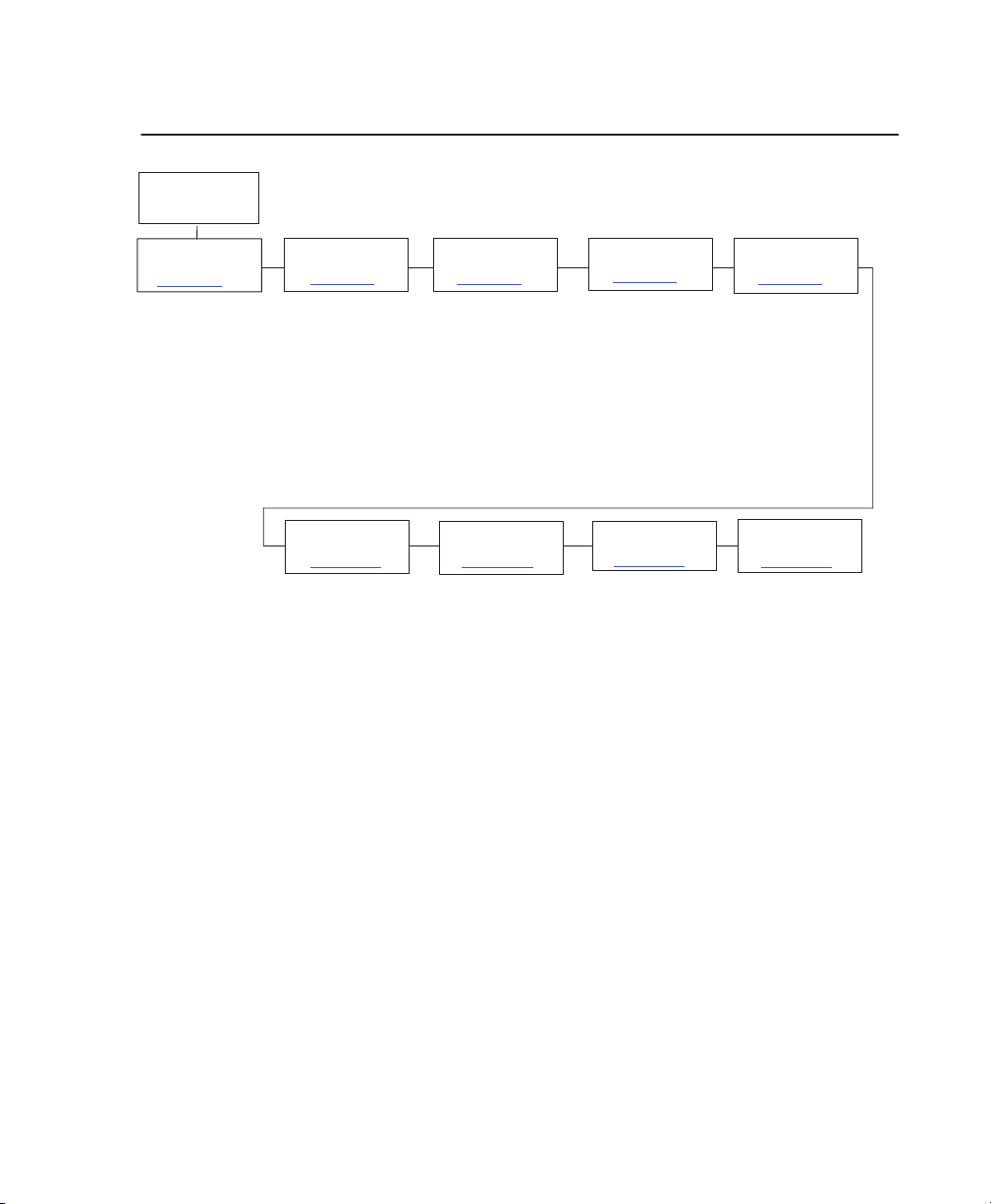
Configuration Main Menu
OFFLINE
CONTROL
page 4–15
Load Config.
Save Config.
Print Config.
Delete Config.
Power–up Config.
Protect Configs.
Name Configs.
Reset Cfg Names
1
If installed.
ACTIVE IGP
1
EMUL
page 4–17
PGL*
VGL
ETHERNET
PARAMS
page 4–1
12
IP Address
Gateway Address
Subnet Mask
MAC Address
* = Factory default
EMULATION HOST
page 4–39
1
CTHI
1
LinePrinter+
44/48XX–ANSI
IGP/PGL
IGP/VGL
IPDS
PRINTER
CONTROL
page 4–1
Unidirectional
PMD Fault
Open Platen @ BOF
Slow Paper Slew
Power Saver T
ear Bar Dist.
T
Shuttle T
1
1
1
13
imeout
1
ime
MAINT/MISCCONFIG.
page 4–91
Hex Dump Mode
Alarm
Power–up State
Display Language
Cancel Key
Eject Function
Power Stacker
Auto Locking
Set Lock Key
Ptx Setup Option
Accented Chars.
File System
Set Sharing
DIAGNOSTICS
page 4–1
Printer T
est Width
T
Paper Out Dots
System Memory
Print Statistics
ests
INTERF
ACE
page 4–97
1
T
winax
1
Coax
Auto Switching
Centronics
Dataproducts
Serial
1
IEEE 1284
Ethernet
RIBBONMINDER
16
page 4–1
New Ribbon
Ribbon Action
Ribbon Size
Ribbon Adjust
Fault Action
1
1
19
Brief descriptions follow for the first–level configuration menu options:
• CONFIG. CONTROL – These options allow you to save, print, load,
delete, name, and reset entire sets of configuration parameters.
• ACTIVE IGP EMUL – This menu allows you to select the PGL or VGL
emulation from the menu if IGP is installed.
• EMULATION – This menu allows you to select the LinePrinter Plus
emulation as the operating emulation for your printer. If the CTHI, IPDS,
ANSI, IGP/PGL or IGP/VGL optional upgrade is installed, then Coax,
T
winax, IPDS, ANSI, IGP/PGL or IGP/VGL will be the active emulation.
Configuration Menus 4–13
Page 67

• MAINT / MISC – These options provide miscellaneous functions, such
as printing a hex dump, selecting a display language, setting the lock
key, and choosing whether the printer will power up in offline or online
mode.
• HOST INTERFACE – These options allow you to select either the Serial
RS–232, Serial RS–422, Centronics parallel, Dataproducts parallel,
Ethernet, IEEE 1284 parallel, Auto Switching, Coax or Twinax interface
for the printer (which must match the interface cabling you installed
while setting up your printer, described in Chapter 2). This menu also
allows you to configure several parameters for each interface.
•
ETHERNET P
IP Address, Gateway Address, and Subnet Mask. The MAC Address
may also be viewed.
• PRINTER CONTROL – These options allow you to select several
operating parameters for the printer, such as the speed at which paper
will advance when slewing.
• DIAGNOSTICS – These options include the diagnostic tests, system
memory, and statistics of the printer.
• RIBBONMINDER – The options in this submenu allow you to enable
the RibbonMinder feature and set its parameters.
ARAMS – This option allows you to view and change the
4–14 Configuration Menus
Page 68
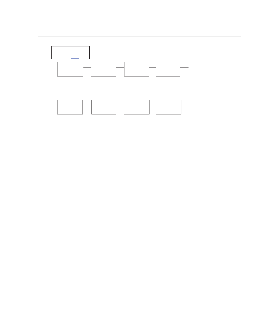
CONFIG. CONTROL Menu
CONFIG.
From
Load
Config.
Factory*
1–8
Power–up
Config.
CONTROL
4–13
Factory*
1–8
Save
Config.
1*–8
Protect
Configs.
Disable*
Enable
Print
Config.
Current*
Factory
Power–up
All
1–8
Name
Configs
1–8
* = Factory default
Delete
Config.
1*–8
Reset Cfg.
Names
1*–8
Load Config.
The printer can store numerous configurations in memory. This parameter allows
you to select and load a specific configuration. The factory default configuration
cannot be changed. It is always available for loading.
Save Config.
This option allows you to save up to eight unique configurations to meet different
print job requirements. This eliminates the need to change the parameter settings
for each new job. The configurations are stored in memory––they will not be lost if
you turn off the printer. If the Protect Configs. parameter is enabled, the new
configuration will not be saved unless the existing configuration has been deleted.
Print Config.
This option is used to output a listing of various stored printer configurations. It is
recommended you store a printout of the configurations in a safe place for quick
referral.
Delete Config.
You can delete one or all of your eight customized configurations.
Power–Up Config.
You can specify which of the nine configurations (Factory or 1–8) will be the
power–up configuration.
Configuration Menus 4–15
Page 69

Protect Configs.
You can specify whether or not a new configuration should overwrite an existing
configuration when you activate the Save Configs. parameter. When disabled
(default), the new configuration will overwrite the existing configuration. When
enabled, the new configuration will
not
overwrite the existing configuration, and
the message “CONFIG. EXISTS / Delete First” displays.
Name Configs.
You can specify a 15 character name which can be used to refer to a
configuration. The name you enter for a configuration will be used in the Load
Config., Save Config., Print Config., Delete Config., and Power–Up Config.
menus. The configuration names are special and apply to the printer rather than
a particular configuration. They are not saved as any part of a configuration, but
stored separately in NVRAM. The names can only be cleared by using the Reset
Cfg Names menu.
When you move into the Name Config menu, the top line of the display shows
the current configuration name string of that configuration. The second line of the
display is initially the same as the top line. You can modify the second line of the
display without affecting the top line until the ENTER key is pressed, selecting
the modified name as the current selection.
A
If you press the NEXT or PREV (
or " ) keys, the cursor will move to the next
or previous character, wrapping to the first or last character. The cursor indicates
the character in the string that will be modified when you press the UP or DOWN
Y or B ) keys. At this point, the UP and DOWN ( Y or B ) keys cycle through
(
the values available for that character at the cursor location. To select another
character to modify, press the PREV or NEXT (
A
or " ) key. Press the ENTER
key at any time to save the configuration name string as shown on the front panel
and move out of this menu. You can press any key other than the ENTER key to
move up and out of this menu. The configuration name string will revert to the
last saved value.
Reset Cfg Name
You can reset specific configuration names back to the default value of the
configuration number.
4–16 Configuration Menus
Page 70

ACTIVE IGP EMUL Menu
ACTIVE
(From
IGP/PGL*
IGP/VGL
IGP EMUL
4–13)
* = Factory default
This ACTIVE IGP EMUL function allows the user to activate either the PGL or the
VGL emulation. There are two methods for selecting the desired emulation. The
first is by selecting the emulation directly from the printer menu. The second is by
sending a host command which will switch the emulation automatically. To switch
from VGL mode to PGL mode, you must be in Graphic Mode.
The command to switch to PGL is SFCC I EMUL, PGL. To switch to VGL from
PGL, you must be in Normal Mode. The command to switch to VGL is SFCC
EMULATION; VGL.
When changing from one IGP emulation to the other, the printer will load the
saved configuration. Thus, any setting performed before selecting those
interfaces and not saved in NVRAM will be lost.
IMPORTANT
In order to configure an IGP emulation, the IGP emulation
must be selected in the ACTIVE IGP EMUL menu.
!
The IGP emulation that is not selected will not appear in
the emulation menu.
Configuration Menus 4–17
Page 71

IGP Configurations – PGL
Features
The PGL emulation is the software based Intelligent Graphics Processor (IGP)
for the line matrix family of Printronix printers. It is based upon, and is compatible
with, the Printronix IGP–100/200/400 board using the Printronix Graphics
Language (PGL). The IGP graphics processing features are detailed below.
On–Line Form and Label Generation makes it easy to create forms or labels
with a “preprinted” look for each application. IGP programs control all graphic
functions, dramatically reducing host computer programming and processing
time.
Graphic capabilities include boxes, vertical and horizontal lines with
user–selectable thickness, logos, and special alphanumeric print features. Forms
and graphic designs can be duplicated horizontally and vertically.
Alphanumeric data can appear as prepositioned “fixed” information (entered
when the form is created), be overlayed onto the form (positioned in a specific
location after the form is created), or may be dynamically merged with the form.
Selectable Bar Codes provide you with the appropriate bar code for your
application using standard wide–to–narrow ratios. A wide selection of bar codes
are available: Code 39, Interleaved 2 of 5, UPC–A, UPC–E, MSI A through D,
Code 128 Subset A, B, and C, EAN/UCC–128, EAN, EAN 13, POSTNET,
POSTBAR, ROY
add–on data.
Expanded and Compressed Character Print attract attention where needed.
Alphanumeric height and width are controlled independently for a wide range of
character sizes up to 113 times the standard character size (up to 11.3 inches
wide and tall). Compressed print sizes of 12, 13, 15, 17, and 20 characters per
inch (cpi) are available.
4–18 Configuration Menus
AL MAIL, and PDF417. UPC and EAN bar codes can specify
Page 72

Rotated Alphanumerics permit new concepts in form design. Normal,
expanded, and compressed character strings can be rotated 90 degrees
clockwise or counterclockwise, or they can be printed upside down.
Logos are created using alphanumeric commands and add many print and
shading features for a “customized” appearance to forms, reports, and labels.
Reversed Print permits highlighting and contrasting by printing white characters
on a dark background.
Automatic Increment/Decrement Capability allows batch form processing. You
can identify individual numeric and bar code data fields, which includes automatic
increment or decrement functions.
Scaling Capability permits graphic elements, such as corners or boxes, to retain
their physical shapes and sizes when printed in a horizontal and vertical density
other than the base density of 60 x 72 dpi.
Standard Character Sets
Standard Character Sets provide you with many different character sets. The
Based on the Multinational Character Set, you may create your own character
sets using characters defined and stored in flash memory.
Configuring the Emulations with the Control Panel
You can select PGL default parameters directly from the control panel, or by
control codes as explained in the
Pressing an invalid key to enter a parameter value may move you to another
level in the configuration or exit the configuration menu completely.
IMPORTANT
BEFORE you reconfigure the PGL, print a
configuration sheet to see all of the current settings.
Programmer’s Reference Manual.
!
Configuration Menus 4–19
Page 73

The IGP/PGL Emulation Submenu
Emulation
IGP/PGL
Define CR
Code
CR
= CR*
CR = CR + LF
Select Font
See
page 4–26
Ext Execute
Copy
Disable*
Enable
Optimized
Ratio
Disable*
Enable
Define LF
Code
LF = LF*
LF = CR + LF
Slash 0
Disable*
Enable
UPC
Descenders
Enable*
Disable
I-2/5
Selection
Leading Zero*
T
railing Space
X2 DPD
* = Factory default
Autowrap Select
Disable*
Enable
Select LPI
6* , 8, 9, 10
Compressed
CPI
Disable*
Light Font
Dark Font
T
rue Form
Slew
Enable*
Disable
Auto
Uppercase
Disable*
Enable
Ignore
Mode
Disable*
Enable
SFCC
1–125
126*
127–255
Ignore
Char.
Printer
PI Line
Enable*
Disable
Select
Char
0*
0–255
PI slew
range
16*
15
Skip Cmd
Prefix
Enable*
Disable
Compatbl.
Mode
None*
MVP
L150
P3000
P6000
P9000
CR edit
Disable*
Enable
Power On
IGP/PGL
Enable*
Disable
Expanded
Font
Scalable*
Block
Alt Block 1
Alt Block 2
Define CR Code (Carriage Return)
This parameter forces the printer to insert an automatic Line Feed code into the data
stream whenever a Carriage Return code occurs. This is to be used only if the host
computer does not send Line Feeds to the printer.
• CR = CR. Does not perform a line feed. The next print position will be
print position 1 of the current line.
• CR = CR + LF. Performs an automatic line feed. The next print position
will be print position 1 of the next line.
4–20 Configuration Menus
Page 74

Define LF Code (Line Feed)
This parameter forces the printer to insert an automatic Carriage Return code
into the data stream whenever a Line Feed code occurs. This can be used in
most installations, but it is required if the host computer does not send Carriage
Returns to the printer.
• LF = LF. Does not perform an automatic carriage return. The next print
position will be the current print position of the next line.
• LF = CR + LF. Performs an automatic carriage return. The next print
position will be print position 1 of the next line.
Autowrap
This parameter determines if text will wrap to the next line when the line of text
exceeds the right margin.
• Disable. Truncates the text beyond the right margin until a CR or CR +
LF is received.
• Enable. Automatically inserts a CR + LF after a full print line.
Select SFCC
You can specify which hex code (1–255) will be used as the Special Function
Control Character (SFCC). The factory default setting is 126. The SFCC denotes
that the following data is a PGL command.
PI Slew Range
You can specify how many lines the paper will feed.
• 15. A paper slew of 1–15 will move 1–15 lines. A paper slew of 0 will
move 1 line.
• 16. A paper slew of 0–15 will move 1–16 lines.
Configuration Menus 4–21
Page 75

CR Edit
This parameter determines if a carriage return will be followed by a line feed.
• Disable. The printer ignores all carriage returns that are not followed by
line feeds.
• Enable. The printer processes all carriage returns, even for those that
are not followed by line feeds.
Select Font
Select Font specifies which language is currently selected for use with the PGL.
Refer to page 4–26 for available selections.
Slash 0
This parameter allows you to print the numeral ‘0’ with or without the slash. This
option applies to all character sets except OCR A and OCR B.
• Disable. Zero is printed without a slash.
• Enable. Zero is printed with a slash.
Select LPI
This is the number of lines to be printed per inch. For example, at 6 lpi there is
1/6–inch from the top of one print line to the top of the next print line.
Auto Uppercase
This parameter enables the printer to print text in all uppercase when using the
ALPHA command.
• Disable. The printer will print text in upper and lowercase.
• Enable. The printer will print text in uppercase only.
Skip Command Prefix
This parameter determines if a data string before a PGL command will be
ignored.
• Disable. The printer will print any data before an IGP command.
• Enable. The printer ignores all text before an IGP command.
4–22 Configuration Menus
Page 76

Power On IGP/PGL
You can set the IGP feature so that it is enabled or disabled when the printer is
powered on.
• Disable. The PGL is disabled when the printer is powered on. (The PGL
feature is initialized to the Quiet mode.)
• Enable. The PGL is enabled when the printer is powered on. (The PGL
feature is initialized in the Normal mode.)
Extended Execute Copy
• Disable. Dynamic data, overlay data, etc. are not allowed if the optional
Form Count parameter (number of forms to print) is specified as part of
the Execute command. (This setting is IGP–100 compatible.)
• Enable. Dynamic data, overlay data, etc. are allowed within a form in
which the Form Count parameter is specified in the Execute command.
In this case, the exact same form (with identical dynamic data, etc.) is
printed for whatever the Form Count is. However, incremental data is
not
incremented since the page that is printing is exactly the same.
Also, each form is printed on a separate page.
UPC Descenders
This parameter allows you to print bar code descenders when human readable
data is not presented in the UPC/EAN bar codes.
• Disable. UPC/EAN bar codes are printed without descenders if there is
no human readable data.
• Enable. UPC/EAN bar codes are printed with descenders, even if there
is no human readable data.
Compressed CPI
This parameter allows you to choose a compressed character (60% shorter) for
17 or 20 CPI instead of the normal height character.
• Disable. The PGL does not use compressed 17 or 20 CPI font.
• Light Font. Uses the standard compressed 17 or 20 CPI font.
• Dark Font. Uses a darker compressed 17 or 20 CPI font compatible
with the IGP–X00 printers.
Configuration Menus 4–23
Page 77

Ignore Character
Ignore Mode
This parameter instructs the PGL to ignore the character selected under the
Select Character menu.
• Disable. The PGL does not ignore any characters.
• Enable. The PGL ignores the characters selected under the Selected
Character menu.
Select Character
This instructs the PGL which character to ignore from the host.
Compatibility Mode
This option instructs the PGL to behave similarly to older versions of the IGP with
respect to certain commands.
All new users with new applications should select the “None” option. Selecting
this mode insures the printer will behave as described in this manual.
When replacing an older product operating with an existing application, especially
those using the PMODE and SMODE commands, a compatibility mode may
need to be selected. In this case, select the printer model number option that
most closely matches the printer being replaced.
Expanded Font
This option defines the type of expanded characters the PGL will select.
• Scalable. These expanded characters have rounded edges.
• Block. These are block characters compatible with the IGP–X00 printers.
• Alt Block 1 / Alt Block 2. Reserved block sets used only for
compatibility purposes.
4–24 Configuration Menus
Page 78

Optimized Ratio
This option selects different bar code ratios for certain bar codes including Code 39
and Interleaved 2 of 5. It is included for compatibility with the IGP–X00 printers.
• Enable. Select the alternate bar code ratios.
• Disable. Use standard bar code ratios.
Interleaved 2/5 Selection
This option is added to be compatible with a special IGP-X00 customization.
Usually, if Interleaved 2/5 bar codes have an odd number of digits, a leading zero
is inserted in front of the data. However, this special IGP-X00 customization adds
a space character at the end of the bar code instead.
• Leading Zero. A leading zero is inserted in front of the data.
• Trailing Space. A space is inserted at the end of the data instead of a
leading zero.
X2 DPD.
•
the specially configured ratios 3:3:6:5 rather than 3:6:9:12 for
compatibility issues.
When selected, I–2/5 bar code with a magnification X2 will use
True Form Slew
This option is related to slewing within forms when using the P–Mode command.
Customers with new applications are advised to keep this option enabled.
• Enable. Form length is accurate according to the form length parameter
in the CREA
• Disable. Form length is IGP–X00 compatible when using P–Mode.
TE command.
Printer PI Line
This option enables the IGP to send down PI instructions to the printer to slew
the form.
• Enable. Send down the PI instructions to the printer (LinePrinter Plus)
during form slew. This is IGP–X00 compatible.
• Disable. Do not send PI instructions to the printer. LFs are sent instead.
Configuration Menus 4–25
Page 79

IGP/PGL Character Set Menu
Select Font
*
= Factory default
Standard Sets*
0) ASCII*
1) German
2) Swedish
3) Danish
4) Norwegian
5) Finnish
6) English
7) Dutch
8) French
9) Spanish
10) Italian
11) Turkish
12–23) Reserved
24–31) User Defined
Code Page 437
Code Page 850
Arabic Sets
ASMO 449*
ASMO 449+
ASMO 708
ASMO 708+
MS DOS CP710
MS DOS CP720
Sakr CP714
Aptec CP715
CP 786
Arabic CP 864
Arabic CP 1046
Arabic Lam One
Arabic Lam T
wo
Cyrillic Sets
Code Page 866*
Cyrillic CP 437
Cyrillic 1
13
Cyrillic 8859–5
ISO 915
Code Page 855
7–bit Cyrillic
European Sets
8859–2 Latin 2*
Latin 2 852
Mazovia
Kamenicky
Roman 8
Slovenian 437
Slovenian 1250
Code Page 865
Code Page 860
Latin 1 8859–1
Latin 5 8859–9
Greek Sets
DEC 256 Greek*
ELOT 928 Greek
Greek 3
ABY Greek
ABG Greek
ELOT 927 Greek
Greek 851
Greek 437
Greek 8859–7
T
urkish Sets Misc. Sets
Data Gen. T
DEC T
urkish
IBM T
urkish
Siemens T
PTT T
IBC T
Bull T
AS400 T
Unisys Turkish
NCR T
PST T
UNIS–1 T
Code Page 853
urkish
urkish
urkish
urkish
urkish
urkish
urkish
urkish
urk.*
Hebrew Sets
Hebrew Old*
Hebrew New
Hebrew DEC
Latin–1 Hebrew
Block–set 10CPI*
Italics Set
4–26 Configuration Menus
Page 80

IGP Configurations – VGL
Features
Code V Graphics language (VGL) is an Intelligent Graphics Printing (IGP)
software emulation designed for your line matrix printer. The IGP Code V
emulation of the QMS
on–line forms, bar codes, and alphanumeric text–generation. The graphics
processing features are detailed below.
On–Line Form and Label Generation
On–Line Form and Label Generation makes it easy to create forms or labels with
the “preprinted” look for each application. VGL programs control all graphics
functions, dramatically reducing host computer programming and processing
time. Graphics capabilities include boxes, vertical and horizontal, solid and
dashed lines with a variety of thickness, logos, and special alphanumeric print
features.
Variable Bar Codes
Variable Bar Codes allow the bar code for your application to print with standard
or user–defined ratios in vertical or horizontal orientations. Available bar codes
are: Codabar, Code 39, Code 93, Code 128 with Subsets A, B, and C, and Code
EAN/UCC 128, EAN 8, EAN 13, Interleaved 2 of 5, MSI, UPC–A, UPC–E,
POSTNET
, POSTBAR, ROY
only in the horizontal direction. A dark print mode is included for darker,
high–contrast bar codes. The IBARC bar code command prints bar codes in four
orientations: horizontal, rotated 90, rotated 180 or rotated 270 degrees.
R
Code Vt Version II programming language produces
AL MAIL, and UPC Shipping. POSTNET is available
Expanded and Compressed Print
Expanded and Compressed Print draws attention where needed. Alphanumeric
height and width are controlled independently for a tremendous range of
character sizes up to 9.9 inches wide and tall. Four compressed print sizes are
available – 12, 13.33, 15, and 17.65 (characters per inch), permitting up to 144
columns in an 8.5–inch printed area (17 cpi).
Configuration Menus 4–27
Page 81

Rotated Alphanumerics
Rotated Alphanumerics permit new concepts in form design. Normal, expanded,
and compressed character strings can be rotated 90 degrees clockwise,
counterclockwise, or printed upside down.
Logos
Logos are easily created using alphanumeric commands and a variety of print
and shading features, providing a “customized” appearance for forms, reports,
and labels. The registered trademark, copyright, TUV, GS–Mark, UL, and CSA
symbols are provided as standard designs on the VGL, and you can also define
custom symbols.
Reverse and Shaded Print
Reversed and Shaded Print permit highlighting and contrasting by printing white
characters on a dark background or white characters on a gray, shaded
background. Various levels or patterns of gray shading and reverse printing may
combine with the many other print features to create distinctive designs.
Automatic Increment/Decrement Capability
Automatic Increment/Decrement Capability allows batch form processing.
Individual alphabetic, numeric, and bar code data fields can be identified and
automatically incremented or decremented by any amount, beginning from a
specified reference point.
Standard Character Sets
Standard Character Sets provide you with many different character sets. The
Based on the Multinational Character Set, you may create your own character
sets using characters defined and stored in flash memory.
4–28 Configuration Menus
Page 82

Configuring the Emulation with the Control Panel
The settings, or configuration parameters, such as selecting the host interface
and parallel/serial data input, are adjusted according to the printer function key
descriptions in this manual. Configure the VGL as you would configure the printer
for other features.
You can select VGL default parameters directly from the control panel, or by
control codes as explained in the
The VGL parameters are described on the following pages. Parameters marked
with an asterisk (*) indicate the default value. The printer must be offline to enter
the configuration structure.
Pressing an invalid key to enter a parameter value may move you to another
level in the configuration or exit the configuration menu completely. Configure the
IGP/VGL according to your specific requirements.
IGP/VGL Programmer’s Reference Manual
.
IMPORTANT
!
BEFORE you reconfigure the IGP/VGL, print a
configuration sheet to see all of the current settings.
Configuration Menus 4–29
Page 83
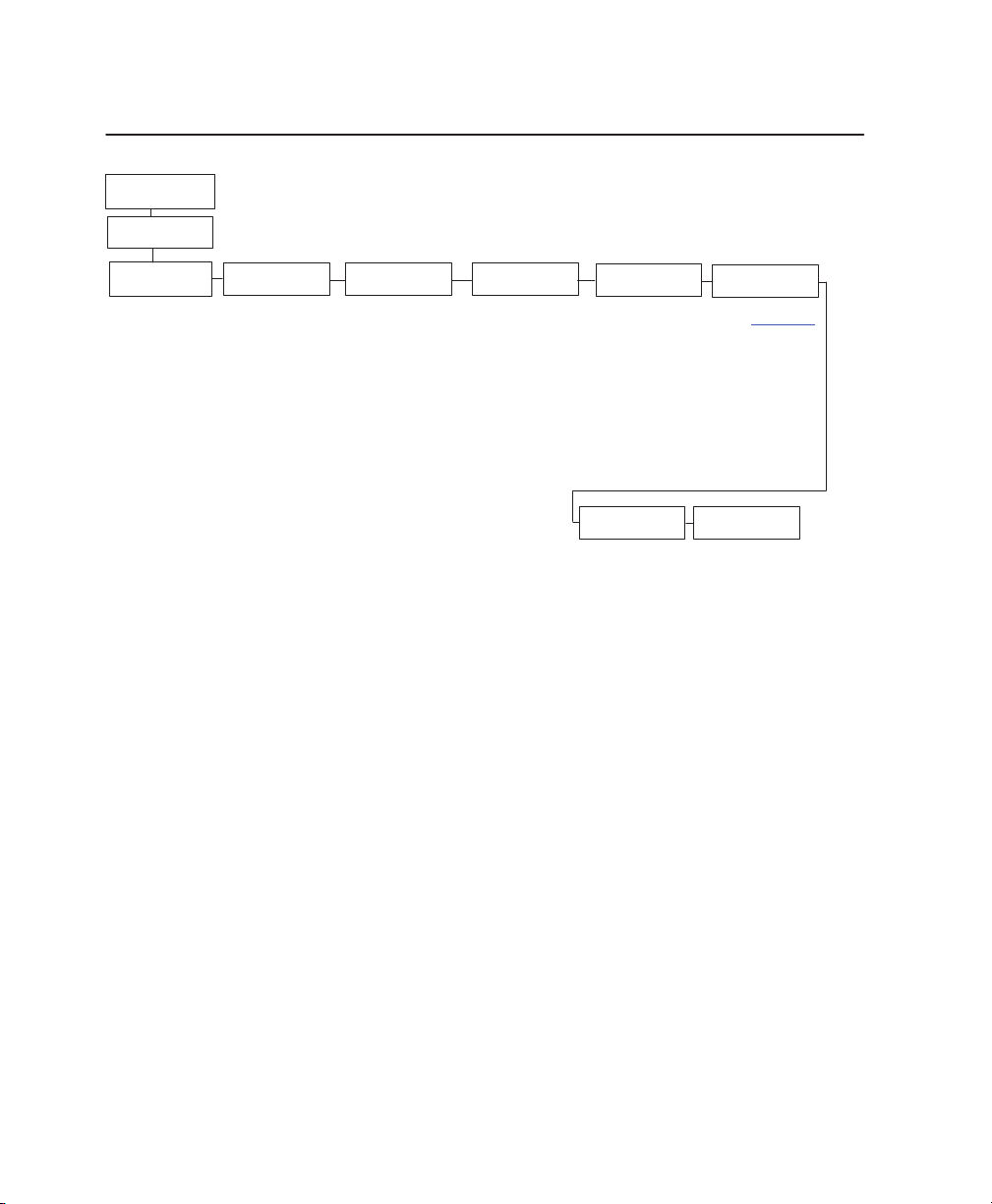
The IGP/VGL Emulation Submenu
EMULATION
IGP/VGL
SFCC
&
Pwrup
94* (range 17–255)
Power Up ^X
Disable*/Enable
Power Up^F
Disable*/Enable
Power Up ^PY
Disable*/Enable
* = Factory default
LPI
6*–10SFCC
Graphics
Options
Slash 0
Disable*/Enable
Ignore Dots
Disable*/Enable
Append Rotated
Disable*/Enable
runcate Alpha
T
Enable*/Disable
rue V
ert 1/10
T
Disable*/Enable
Absorb after ^PY
Absorb Motion*
Absorb All
Disable
UPC Descenders
Enable*/Disable
Rot. Char Size
Adjusted*/Not Adjusted
Ignore Spaces
Disable*/Enable
Midline PY
Disable*/Enable
Dark barcode
Disable*/Enable
Expanded Font
Scalable*
Block
Width Limit
Disable*/Enable
IGP 1
10 Compatbl.
Disable*
Enable
Error
Handling
Error msgs
Enable*/Disable
Error markers
Enable*/Disable
fpage errors
Of
Disable*/Enable
Barcode errors
Enable*/Disable
Ignore/DB8
Setup
Ignore chars
Disable*
Char 1
Char 2
Char 1 & 2
Ignore ch#1
0* –255
Ignore ch#2
0* –255
Data Bit 8
Enable*/Disable
PI Control
Printer PI
Disable*/Enable
Host PI
Disable*/Enable
Max PI 16
Enable*/Disable
Font Set
See
page 4–38
Prt to
Emulate
Disable*
MVP/MVP 150B
L150
P3040
P6000
P9000
SFCC & Pwrup
This option has several suboptions that determine the SFCC and power–up
configuration that will be used with VGL.
SFCC
This option selects the Special Function Control Character. The default value is
the caret ^ (decimal 94). Valid values are 17 through 255. Throughout this
manual, the caret is used as the SFCC. Obtain a configuration printout to
determine the currently selected SFCC.
4–30 Configuration Menus
Page 84

Power Up ^X
Enable selects the ignore mode as the power–up default, and selects the
graphics mode ^PY as the power–up default. All characters are ignored until a ^A
command is received.
Power Up ^F
Enable selects free format as the power–up default, and selects the graphics
mode ^PY as the power–up default. Free format causes the VGL to ignore
carriage returns, line feeds and all characters below 20 hex sent from the host.
Power Up PY
Enable selects the graphics mode ^PY as the power–up default.
LPI
This is the number of lines to be printed per inch. For example, at 6 lpi there is
1/6–inch from the top of one print line to the top of the next print line.
Graphics Options
Following are several options that configure printing output.
Slash 0
This parameter allows you to print the numeral ‘0’ with or without the slash. This
option applies to all character sets except OCR–A and OCR–B.
• Disable. Zero is printed without a slash.
• Enable. Zero is printed with a slash.
Ignore Dots
Enable causes the VGL to expect position values to be specified in only 1/10ths
of an inch. If the dot position is also given, it is treated as text.
Configuration Menus 4–31
Page 85

Append Rotated
Enable appends logos to an alphanumeric string rotated in a clockwise,
counterclockwise, or inverted orientation. Otherwise, the logo is treated as a
separate element.
Truncate Alpha
When enabled, this parameter prevents the printing of Error 48 (Element Off Page
Error) if alphanumeric data, including spaces, extends beyond the right side of the form.
T
rue V
ert 1/10
Determines if a vertical 1/10 of an inch parameter is used as 1/10 of an inch
(Enabled) or as 7/72 of an inch (Disabled). When used as 1/10 of an inch,
rounding will occur to the nearest 1/72 of an inch. This can cause vertical moves
that have the same value to differ by 1/72 of an inch. When used as 7/72 of an
inch, the absolute move is slightly smaller than expected. For example, a one
inch move would be 70/72 of an inch. Vertical moves that have the same value
will be identical in length.
Absorb after ^PY
Absorb motion prevents paper motion following a system terminator in a graphics
^PY command. When absorb all is selected, the system ignores all the data and
terminator until a host generated terminator is detected. When disabled, system
terminators following a graphics command are sent to the printer and result in
paper motion.
UPC Descenders
This parameter allows you to print bar code descenders for human readable data
in the UPC/EAN bar codes.
• Disable. UPC/EAN bar codes are printed without descenders if there is
no human readable data.
• Enable. UPC/EAN bar codes are printed with descenders, even if there
is no human readable data.
4–32 Configuration Menus
Page 86

Rot. Char Size
When the Rotated Character Size option is Adjusted, rotated
(clockwise/counter–clockwise), expanded characters have a different size than
an unrotated character with the same size parameters. If Not Adjusted, rotated,
expanded characters will be the same size as unrotated characters with the
same size parameters.
Ignore Spaces
When disabled, trailing spaces are NOT deleted from alphanumeric elements in a
graphics pass. When enabled, trailing spaces are deleted from alphanumeric
elements in a graphics pass.
Midline ^PY (includes ^PN)
When disabled, the Graphics mode Enabled command, ^PY, must be the first
three characters of a line. When enabled, the ^PY or ^PN can occur anywhere in
a line.
Dark barcode
When enabled, bar codes will be printed in dark mode no matter what the dark
mode is set for. If this option is disabled, dark mode printing will only occur if the
dark mode command is sent before the bar code command.
Expanded Font
• Scalable: These expanded characters have rounded edges.
• Block: These are block characters compatible with the IGP–X10
printers.
Width Limit
When enabled, the system will limit the length and width for expanded characters
to a limit shown in the following table. Table 4–1
allowed for a specific height in the range of 00 to 40 (0.0 to 4.0 inches).
Configuration Menus 4–33
shows the maximum width
Page 87

IGP 110 Compatible
This option instructs the VGL to behave similarly to the IGP–110 with respect to
certain commands. All new users with new applications should select the
“Disable” option. Selecting this mode insures the printer will behave as described
in this manual.
• Disable. The IGP does not emulate the IGP–110 mode.
• Enable. The IGP emulates the IGP–110 version.
Table 4–1. Width Limit Table
Height
Param.
00 99 21 51
01 99 22 53
02 3 23 56
03 6 24 58
04 8 25 61
05 11 26 63
06 13 27 66
07 16 28 68
08 18 29 71
09 21 30 73
10 23 31 76
11 26 32 78
12 28 33 81
13 31 34 83
14 33 35 86
15 36 36 88
16 38 37 91
17 41 38 93
18 43 39 96
19 46 40 98
20 48
Max. W
Allowed
idth
Height Param.
Max. W
Allowed
idth
Error Handling
Following are several options that configure how errors are reported.
Error msgs
When enabled, command syntax is checked and error messages printed when
command parameters are incorrect. When disabled, error checking and error
messages are suppressed.
4–34 Configuration Menus
Page 88

Error markers
Enable prints the following error markers for those elements that print beyond the
page boundaries:
>> for elements that begin off the right side of the page;
<< for elements that begin at the indicated position but end off the page;
◆ for elements where the starting position of the command contains
an error other than an off-page error.
Offpage Errors
When enabled, reports errors for elements that start or end beyond the right edge
of the page. When disabled, does not report these errors.
Barcode Errors
When enabled, an error message will print when invalid bar code data is
encountered. When disabled, VGL will not print an error for illegal bar code data;
the bar code will be skipped.
NOTE: When bar code error is disabled, VGL emulation will try to make the
best use of invalid data by either truncating extra digits or adding
zeros to the end of bar code data to meet minimum data length
requirements for some bar codes. Not all errors will be corrected.
Ignore / DB8 Setup
Determines if character filtering is enabled, or if one or both characters are
ignored.
• DISABLE. Character filtering is not enabled.
• Char 1. Character 1 will be filtered. Select the option Ignore ch#1 to
specify character 1.
• Char 2. Character 2 will be filtered. Select the option Ignore ch#2 to
specify character 2.
• Char 1&2. Characters 1 & 2 will be filtered. Select the options “Ignore
ch#1” and “Ignore ch#2“ to specify values for these characters.
Configuration Menus 4–35
Page 89

Ignore ch#1
Specifies character 1 for the character filtering option. Valid values for
0 through 255.
Ignore ch#2
Specifies character 2 for the character filtering option. Valid values for
0 through 255.
Data Bit 8
When data bit 8 is enabled, the PI line is not passed directly from host to printer;
all 8 bits are used for data bits, and characters in the 80–FF hex range can be
accessed.
When data bit 8 is disabled (and the host PI line is enabled), data bit 8 internally
indicates PI line status. To use the PI line, disable data bit 8, and enable the Host
PI configuration option (under the PI Control option on page 4–37
NOTE: Data bit 8 is interpreted as
both. When enabled as data bit 8, data bit 8 has priority over the PI
signal, and all data above 7F hex is used to access character data
and not to interpret PI line data.
either
data bit 8 or PI signal, but never
).
n
are from
n
are from
Conversely, when data bit 8 is disabled and the PI signal is used, data bit 8 of the
data is reserved for use as the PI function, and you cannot access characters in
the 80–FF hex range. Therefore, to access characters in the 80–FF hex range,
data bit 8
must
be enabled.
Font Set
The Font Set specifies which language is currently selected for use with the VGL.
Refer to page 4–38 for available selections.
4–36 Configuration Menus
Page 90

PI Control
Printer
Disable indicates that the ASCII emulation is configured with the PI line disabled.
Setting this option to Enable informs the VGL that the ASCII emulation is
configured with the PI line enabled.
Host PI
Disable indicates the host does not send PI signals. Setting this option to Enable
informs the VGL that the host sends PI signals. The Data Bit 8 configuration
option must be disabled to transmit the PI line to the printer.
Max PI 16
This parameter determines if the range for a paper slew is from 1 to 15 lines or 1
to 16 lines. If this option is set to enable, a paper slew of 0–15 will move 1–16
lines. If this option is set to disable, A paper slew of 1–15 will move 1–15 lines. A
paper slew of 0 will always move 1 line.
PI
Prt to Emulate
This option allows you to select an earlier model printer/IGP board combination to
emulate. When a printer emulation is selected, the scaling command causes the
printer to generate a graphic image in the same density as the printer emulation
chosen. Five types of printers can be emulated: MVP or MVP 150B, L150,
P3040, P6000, and P9000. Once a particular printer emulation is selected, it
remains active until the printer is turned off or another printer emulation is
selected. All new users with new applications should select the “Disable” option.
Selecting this mode insures the printer will behave as described in this manual.
The other compatibility modes are required to emulate the behaviors of older
printers that may be inconsistent with the documented VGL functionality. Proper
use of this feature requires the printer to be equipped with high resolution
hammer bank tips (12 mil).
Configuration Menus 4–37
Page 91
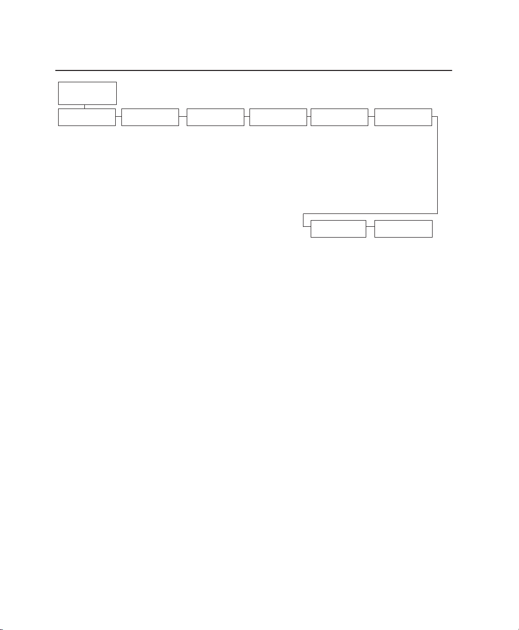
IGP/VGL Character Set Menu
Font Set
*
= Factory default
Standard*
0) ASCII*
1) German
2) Swedish
3) Danish
4) Norwegian
5) Finnish
6) English
7) Dutch
8) French
9) Spanish
10) Italian
11) Turkish
Code Page 437
Code Page 850
Arabic Sets
ASMO 449*
ASMO 449+
ASMO 708
ASMO 708+
MS DOS CP710
MS DOS CP720
Sakr CP714
Aptec CP715
CP 786
Arabic CP 864
Arabic CP 1046
Arabic Lam One
Arabic Lam T
wo
Cyrillic Sets
Code Page 866*
Cyrillic CP 437
Cyrillic 1
13
Cyrillic 8859–5
ISO 915
Code Page 855
7–bit Cyrillic
European Sets
8859–2 Latin 2*
Latin 2 852
Mazovia
Kamenicky
Roman 8
Slovenian 437
Slovenian 1250
Code Page 865
Code Page 860
Latin 1 8859–1
Latin 5 8859–9
Greek Sets
DEC 256 Greek*
ELOT 928 Greek
Greek 3
ABY Greek
ABG Greek
ELOT 927 Greek
Greek 851
Greek 437
Greek 8859–7
T
urkish Sets Misc. Sets
Data Gen. T
DEC T
urkish
IBM T
urkish
Siemens T
PTT T
IBC T
Bull T
AS400 T
Unisys Turkish
NCR T
PST T
UNIS–1 T
Code Page 853
urkish
urkish
urkish
urkish
urkish
urkish
urkish
urkish
urk.*
Hebrew Sets
Hebrew Old*
Hebrew New
Hebrew DEC
Latin–1 Hebrew
Block–set 10CPI*
Italics Set
4–38 Configuration Menus
Page 92

EMULATION Menu
* = Factory default
The
EMULATION
(From
CTHI
LinePrinter+*
Proprinter XL
Epson FX
P–Series*
P–Series XQ
Serial Matrix
44/48XX–ANSI
IGP/PGL
IGP/VGL
IPDS
1
Optional emulation
EMULA
4–13)
1
1
1
1
1
TION menu allows you to select the emulation to be used with your
printer. The Proprinter XL, Epson FX, P–Series, P–Series XQ, and Serial Matrix
emulations are all part of LinePrinter Plus. You can configure options for the
active emulation via the EMULATION menu. Emulation options are further
described in their corresponding programmer’s reference manual.
Configuration Menus 4–39
Page 93
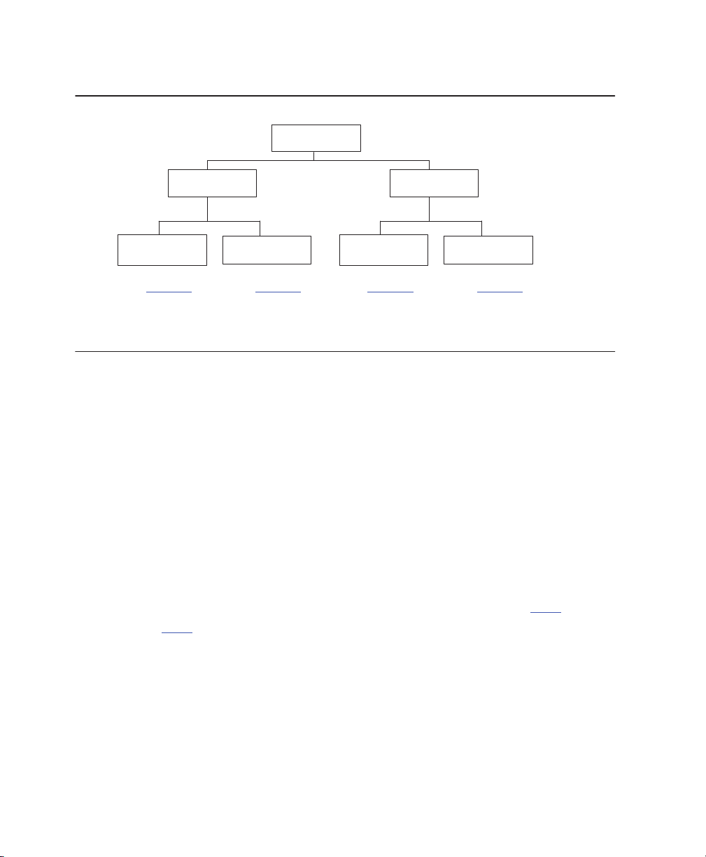
Coax/Twinax Menu Overview
CTHI
Coax Params
See
page 4–41
Standard*
T
winax Params
See
page 4–50
See
SPC Coax
Params
page 4–55
Simp Prot Conv
See
SPC T
Params
page 4–57
wx
Coax/Twinax Emulations
With a coax interface, the printer emulates the following IBM coax printer models:
• 3287 Models 1 and 2
• 4234 Models 1
With a twinax interface, the printer emulates the following IBM twinax printer
models:
• 4234 Models 2 and 12
• 5225 Models 1, 2, 3, and 4
These emulations are discussed on the following pages.
NOTE: The CTHI emulation selection will only be available if Coax or
Twinax is selected from the HOST INTERFACE menu. See page
4–97.
4–40 Configuration Menus
Page 94
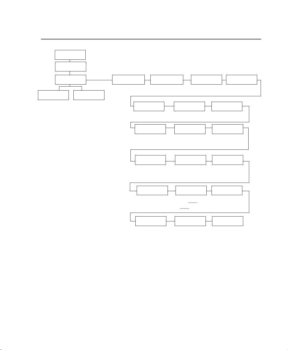
Coax Emulation Menu
Standard*
Coax Params
Char Set Select
0037 English US*
0037 Eng Nether
0285 English UK
0273 Austr/Germ
0274 Belg. Old
0275 Brazilian
0260 Canad Fren
0277 Danish
0287 Danish Alt
0278 Finnish
0288 Finn. Alt
0297 French
0500 Internat 5
0280 Italian
0281 Japan. Eng
0282 Portuguese
0284 Span Speak
0289 Span. Alt
0500 Swiss Bil
0500 Belg. New
0803 Hebrew Old
0424 Hebrew
0892 OCR A
0893 OCR B
0420 Arabic
0880 Cyril. Old
0423 Greek Old
0875 Greek New
0871 Icelandic
0290 Japan Kata
0870 Latin 2
0838 Thai
1026 T
urkish
0890 Y
ugos. Old
1097 Farsi
1025 Cyrillic
0905 T
urk. Old
0256 Intern. 1
Secondary SetsPrimary Sets
English US*
English UK
Austrian/German
German (Alt)
Belgian
Brazilian
Canadian French
Danish/Norweg.
Danish (Alt)
Finnish/Swedish
Finnish (Alt)
French
International
Italian
Japanese Eng.
Japanese Katak.
Portuguese
Portug. (Alt)
Spanish
Spanish (Alt)
Spanish Speak.
Swiss Fren/Ger
Old Hebrew
Hebrew
Farsi/Latin
Greek Old
Greek New
Arabic
Turkish
urkish Old
T
Latin2/ROECE
Yugoslavian
*
= Factory default
T
ranslation Tbl Prt Partial Line
.
Active Char Set
Secondary Set*
Primary Set
PA2
Early Print Cmpl
Disable*
Enable
Change Case
Dual Case*
Mono Case
Intervention
Req
Send to Host*
Do Not Send
Host Override
Disable*
Enable
Enable*
Disable
Buf
fer Reprint
Cancel
IGP/DCU
Enable*
Disable
Set T
ext
Orientn
Control By Host*
Left to Right
Right to Left
Compatibility
Op
See
page
4–47
Format Control
Disable*
Enable
Device ID
4234*
3287
PTX
Transparent
Set 1 <%>*
Set 2
þþ$
Set 3 _%_
Image Buf Size
4K*
2K
Translate
Table
Default*
Downloaded
Buf
fer Print
Disable*
Enable
PA1
Configuration Menus 4–41
Page 95

Char Set Select
CHAR SET SELECT specifies the print language used by the printer. Character
sets are shown in detail in the
Character Sets Reference Manual
.
Translation Table
TRANSLATION TABLE prints out SCS and DSC/DSE tables of coax interface’s
current character set. This operation is valid only when coax interface is the
current interface.
Active Char Set
This option selects which group of character sets will be active.
Prt Partial Line
When this option is enabled, it forces the printer to print if a partial line is in the
printer (i.e. line not ending with a LF). When disabled, the last partial line of data
will not be printed.
PA1
PA1 is only valid when the printer is in the NOT READY state and the coax
System Network Architecture Character Set (SCS) data stream is active. This
function displays the “PA1 ENABLED” message when the ENTER key is pressed
and sends a special operator request to the host when the printer is made
READY. Refer to the
about SCS.
Programmer’s Reference Manual
for more information
NOTE: Selecting the PA1 menu item again (“PA1 DISABLED” appears on
the operator panel) or selecting the PA2 menu item will reset the
pending PA1 function.
PA2
PA2 is only valid when the printer is in the NOT READY state and the coax SCS
data stream is active. This function displays the “PA2 ENABLED” message when
the ENTER key is pressed and sends a special operator request to the host
when the printer is made READY.
4–42 Configuration Menus
Page 96

NOTE: Selecting the PA2 menu item again (“PA2 DISABLED” appears on
the operator panel) or selecting the PA1 menu item will reset the
pending PA2 function.
Buffer Reprint
This option is valid only when the printer is printing in SCS mode. When the
ENTER key is pressed, “Buffer Reprint Enabled” is displayed and an Intervention
Required status is sent to the host. Pressing ENTER again cancels the Buffer
Reprint function and “Buffer Reprint Disabled” is displayed.
Device ID
This parameter defines the printer emulation, as follows:
• 3287
• 4234
After the emulation has been changed, a POR status is sent to the host.
Early Print Complete
Early Print Complete capability allows the printer to send print (order) complete
status to the host before the printer is actually done printing all data. This option
is valid only when the printer is in DSC/DSE mode.
• ENABLE means the printer will send an acknowledgement to the host
when it is able to accept more data.
• DISABLE means the printer will suppress the Early Print Complete
response until all printing is complete.
NOTE: When an Early Print Complete is enabled and an error occurs,
there may be data loss experienced.
Cancel IGP/DCU
• ENABLE cancels all buffers when a job is put on hold from the host or
when the CANCEL key is pressed.
• DISABLE does not cancel any internal buffer in the printer when a job is
put on hold from the host, or when the CANCEL key is pressed.
Configuration Menus 4–43
Page 97

PTX Transparent Control
You can enable additional printer features that are not accessible through
standard Coax emulations. To access these features, send text commands in the
data stream. The commands must have a start and end code. Three sets (each
containing a start and end code) are available:
• Set 1: start code =<%
end code = >
• Set 2: start code =
end code = $
• Set 3: start code = _%
end code = _
þþ
Change Case
CHANGE CASE specifies the font as MONO or DUAL case. It is available only in
non-SCS mode. The host will be notified of the change when the printer is made
READY. If the character set is one of the following ‘right to left’ sets, MONO
CASE prints the same as DUAL CASE: Katak., Hebrew, Old Hebrew, and Farsi.
SCS (System Network Architecture Character String) Mode is controlled by the
host computer.
Set Text Orientn
SET TEXT ORIENTATION specifies the direction in which characters are printed
on the page. This allows the printer to print languages which are printed right to
left instead of left to right.
• CONTROL BY HOST
• LEFT TO RIGHT
• RIGHT TO LEFT
The “CONTROL BY HOST” option allows printers configured as a 4234 to use
the “SET TEXT ORIENTATION” command from the host. When a RIGHT TO
LEFT language is selected, the host will be notified of print direction changes
when the printer is made READY.
4–44 Configuration Menus
Page 98

Image Buf Size
IMAGE BUFFER SIZE (screen buffer size) allows you to select the following
image buffer sizes. This option is only valid when printer emulates 3287. For the
4234 emulation, the buffer size is fixed at 4k. A POR status is sent to the host
when the printer is made READY.
• 2K
• 4K
Intervention Req
Select from SEND TO HOST or DO NOT SEND. If SEND TO HOST is selected,
the printer sends a signal to the host computer when any of the following occur:
• Printer faults occur.
• Hold mode time-out occurs.
Translate Table
This parameter defines which translate table to use for printing. The following
options are available:
• DEFAULT translates data by using the default table of the current
character set.
• DOWNLOADED translates data from EBCDIC to internal code by using
the downloaded translate table.
Host Override
HOST OVERRIDE determines whether the printer accepts certain commands
sent by the host, or continues to use the current operator panel settings. The
following host commands are ignored when HOST OVERRIDE is enabled: line
length, forms length, lines per inch (LPI), characters per inch (CPI), print quality,
and text orientation (i.e. left to right). When HOST OVERRIDE is enabled, these
settings retain their operator panel settings.
Configuration Menus 4–45
Page 99

• DISABLE allows certain host commands (line length, forms length, LPI,
CPI, print quality, and text orientation) to override operator panel
settings. Note that the information appearing on the message display
may
not
match the data stream setting. No values will change upon
initial selection of the disable option.
• ENABLE permits operator panel settings to override host data stream
commands.
Format Control
FORMAT CONTROL enables the printer to reflect the same spacing as CTPC
model printers after absolute and relative move commands are executed. The
following options are available:
• DISABLE reflects distance, generated by the IGP/VGL feature, IGP/PGL
feature, and Hex Transparent control code sequence, in the new
position (after horizontal and vertical tabs are executed).
• ENABLE does not reflect distance, generated by the IGP/VGL feature,
IGP/PGL feature, and Hex Transparent control code sequence, in the
new position (after horizontal and vertical tabs are executed).
Buffer Print
When enabled, the BUFFER PRINT parameter prints the EBCDIC data and
control codes received from the host as hex values. Refer to Chapter 6 for
information on how to obtain a hex code printout.
NOTE: Use of this parameter may alter print attributes set by the host
computer. A power cycle may be required after changing BUFFER
PRINT from enable to disable.
4–46 Configuration Menus
Page 100
Compatibility Options Menu (Coax Only)
The Compatibility Options menu allows you to select special printer functions in
the non-SCS mode, based on the capabilities of the printer emulated.
Compatibility
From
page 4–41
CR at MPP +1
On*
Off
Op
NL at MPP +1
On*
Off
V
alidity
FF
Off*
On
(4234 only)
Position Aft FF
Off*
On
Auto
Skip
at End
Off*
On
* = Factory default
Last Char=FF
On*
Off
FF After Job
Off*
On
Null
Suppression
Off*
On
(3287 only)
CR, EM, & NL
On*
Off
CR at MPP+1
MPP is Maximum Print Position, which is also known as line length. This option
controls a carriage return at the end of a print line and at MPP+1.
• OFF produces a carriage return to the first print position of the current
line.
• ON produces a carriage return to the first print position of the next line.
NL at MPP+1
NL AT MPP+1 controls how many lines are skipped when the carriage returns to
a new line.
• OFF moves to the first print position of the next print line.
• ON moves to the first print position two lines down from the current
position.
Configuration Menus 4–47
 Loading...