

Page 1
ODV2D-V2 Installation Instructions
1
Page 2

Table of Contents
1. ODV2D-V2 Installation ..................................................................... 3
2. Preparing the Printer ........................................................................ 4
3. Replace Original Peel/Tear Door Assembly ..................................... 5
4. Install ODV2D-V2 Interface PCBA and Cable .................................. 5
5. Installing ODV2D-V2 and Mounting Bracket to Printer ................... 11
6. Coarse Mechanical Alignment ....................................................... 13
7. Prepare for Alignment/Calibration .................................................. 17
8. Alignment ....................................................................................... 27
9. Calibration ..................................................................................... 33
10. Functional Testing ..................................................................... 37
11. Options ...................................................................................... 39
12. Maintenance .............................................................................. 39
13. Spare Parts ............................................................................... 39
14. Troubleshooting ........................................................................ 40
2
Page 3

1. ODV2D-V2 Installation
Field Installation
This procedure is for use with the ODV2D-V2 assembly. The ODV2D-V2 is a precise measurement device. Once
properly installed, it will perform well in even harsh environments with reasonable care. Installation must be done by
trained service personal. This requires special tools and knowledge of the calibrating system with the printer.
Parts Included in the Field Kit (P/N P220340-001)
• ODV2D-V2 Validator (P/N P220342-001) w/Mounting Bracket (P/N P220343-001)
• Mounting Bracket Screws (3 ea. M4x10mm)
• ODV2D-V2 Peel/Tear Door Assembly (P/N P220293-001)
• ODV2D-V2 Interface PCBA (P/N P220141-001/spare P220291-001)
• ODV2D-V2 Power/Data Ribbon Cable Assembly (P/N P200026-001)
• Ferrite Core
• Wire Saddle
• Split Grommet
• Cap for center-line access hole
• Printronix Calibration Plaque (P/N P220237-001/spare P220292-001)
• Package of 4x6 inch Direct Thermal Liner Gap Fanfold Media
• Alcohol wipes (P/N P200016-002)
Required Tools and Materials
• Static Wrist Strap
• Long Nose Pliers
• Flat Blade Screwdriver
• Metric Hex Keys (2, 2.5, and 3mm – P200080-001, P200081-001, P200083-001)
• Metal Square, 6in w/Bubble Level (P200084-001)
• All special tools available in ODV2D Tool Kit (P/N P220329-001)
• T8 Administrator’s Manual (P/N 258745-001)
• ODV2D User’s Manual (P/N P180045-000)
T8X04 Printer Requirements
• T8204 and T8304 4-inch wide printer only.
• Media thickness range supported = 0.0025 – 0.010 inches.
• Upgrading an older printer will require downloading new printer software.
• Supports Continuous, Tear-Off Strip, Tear-Off, Peel-Off, Cutter*, and Batch Rewind Media Handling Modes.
NOTE: *A Cutter option is available using the Cutter assembly designed specifically for use with the ODV2D-V2 (P/N
P220348-001)
3
Page 4

2. Preparing the Printer
NOTE: If the Peel/Tear door, ODV2D-V2 Interface PCBA and Data/Power ribbon cable are pre-installed, skip forward to
section 5. Installing Mounting Bracket to Printer
1. Set the printer power switch to O (Off). Switch located on rear of printer.
WARNING Always unplug the printer power cord from the printer or the power outlet before doing any
installation procedure. Failure to remove power could result in injury to you and damage the
equipment. You will be instructed when to apply power.
2. Unplug the printer power cord from the printer or the AC power source.
4
Page 5
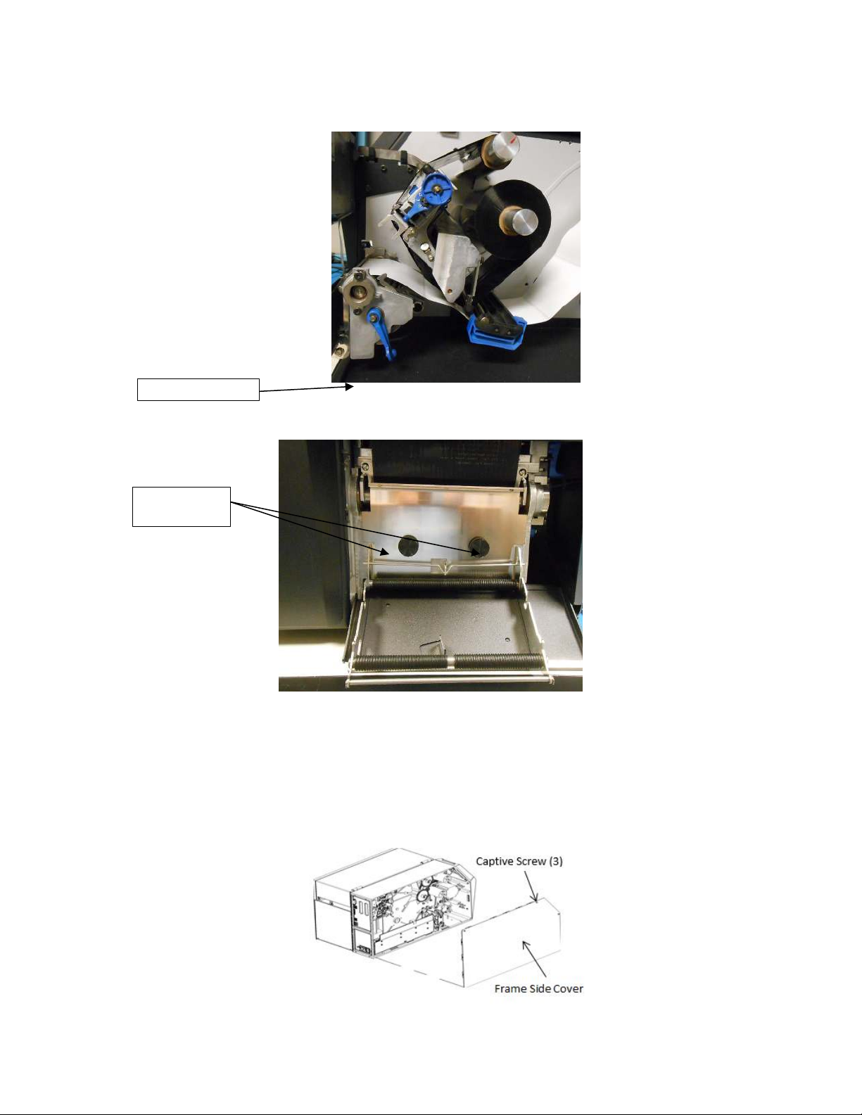
3. Replace Original Peel/Tear Door Assembly
Deck Lock Lever
M5x16mm
Thumb Screws
Figure 3: Removing the Frame Side Cover
1. Open the pivoting deck on the printer by rotating the deck lock lever fully clockwise. Remove the two thumbscrews
on the existing Peel/Tear Door assembly and remove the assembly from the printer and set it aside.
Figure 1: Open Deck Locking Lever, remove Peel/Tear plate
2. Install the ODV2D-V2 Peel/Tear Door Assembly, provided in the kit, to the front of the printer. Secure the door to the
printer with the two M5x16mm thumb screws provided. Bias the door downwards while tightening the screws.
Figure 2: Install new Peel/Tear plate using thumb screws provided
4. Install ODV2D-V2 Interface PCBA and Cable
1. Use a 2.5mm hex key to loosen the three captive screws securing the frame side cover.
2. Tilt the side cover out from the top and lift it up until the tabs along the lower edge disengage from the slots in the
base of the printer.
5
Page 6
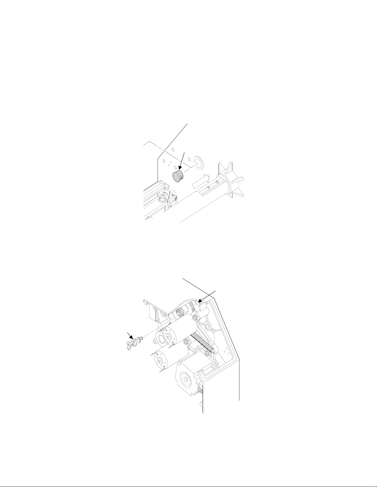
Frame Boss
Wire Saddle
Plastic Plug
CAUTION: To prevent electrostatic damage to electronic components, always wear a properly grounded static
wrist strap when you work around the printed circuit boards.
3. Put on a static wrist strap and ground it to an unpainted part of the printer frame. Touch the frame with the hand
wearing the wrist strap.
4. Raise the media cover and remove the plastic plug from the frame opening and set it aside.
Figure 4: Removing the Plastic Plug
5. On the electronics side of the printer, use long nose pliers to hold and insert the provided wire saddle into the
frame boss opening.
Figure 5: Installing the New Wire Saddle
6
Page 7
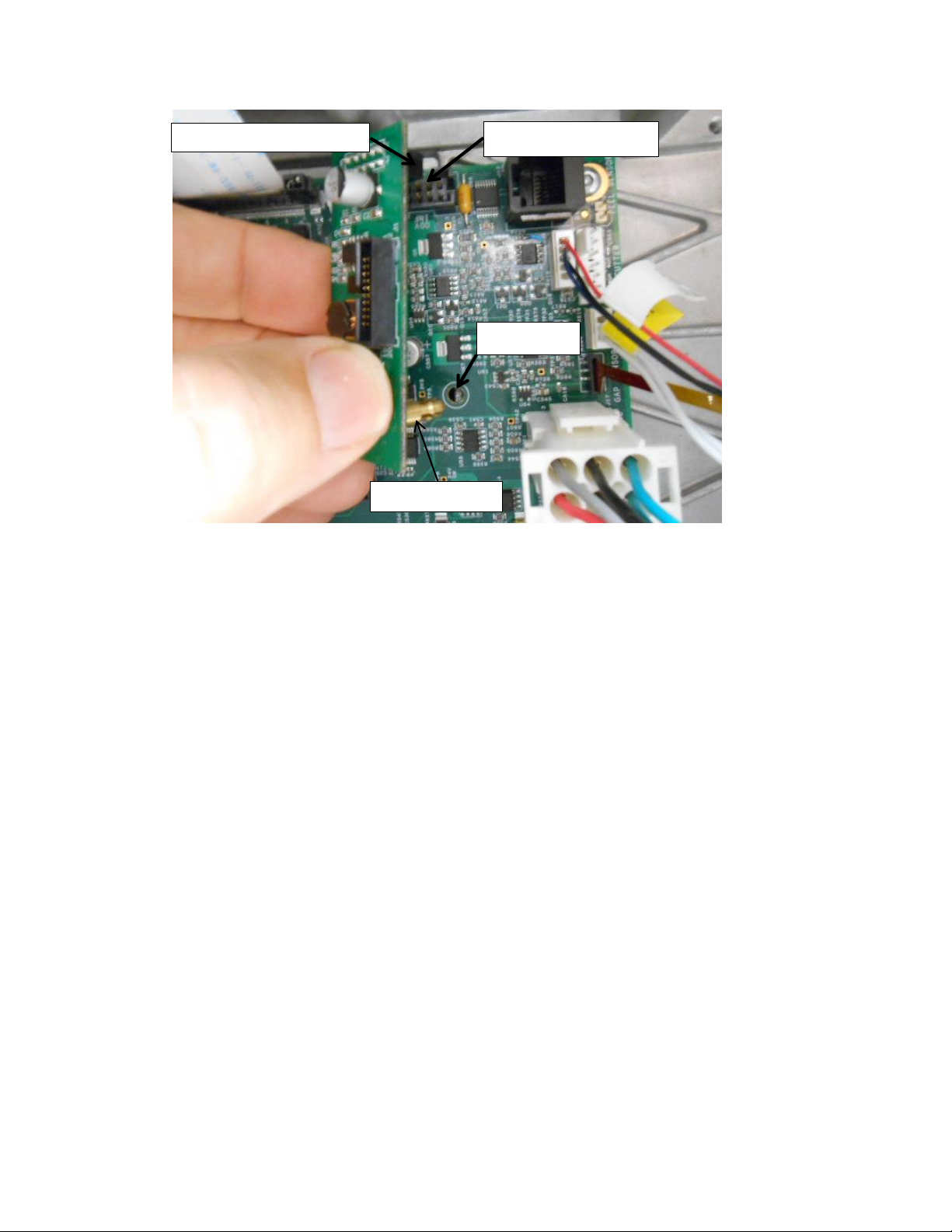
6. Install the provided ODV2D-V2 Interface PCBA by plugging its connector into J10 at the top right side of the
J10 Controller PCBA
Brass Standoff
PCBA Hole
ODV2D-V2 I/F PCBA
Controller PCBA and its brass standoff into the mating hole in the Controller PCBA.
Figure 6: Installing the ODV2D-V2 Interface PCBA
7
Page 8
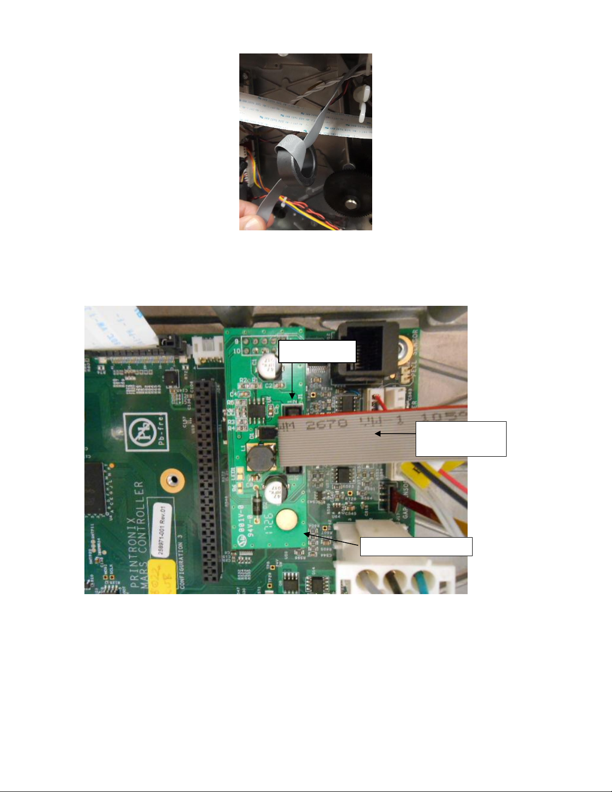
7. Wrap the ODV power/data flat cable one time around the ferrite core provided in the kit.
ODV2D-V2
Power/Data Cable
ODV2D-V2 I/F PCBA
J1 Connector
Figure 7: Wrapping the Power/Data Cable around the Ferrite Core
8. Plug the Power/Data cable into J1 of the ODV2D-V2 Interface PCBA.
Figure 8: Plugging the Power/Data Cable into the ODV2D-V2 Interface PCBA
8
Page 9

New Wire Saddle
ODV Power/Data Cable
next to ribbon motor
ODV Power/
Data Cable
ODV Power/Data
Cable through ferrite
core. Secure with tiewrap to wire saddle.
Control Panel Cable
Figure 9: Routing the Power/Data Cable through Two Wire Saddles and Ferrite core
9. On the electronics side of the printer, route the ODV2D power/data flat cable through the existing wire saddle on
the left that holds the lower media, label taken and pivoting deck lock sensor cables, then through the new wire
saddle. Lock the ends of the wire saddles to constrain the cables. Secure the Ferrite Core to the wire saddle
using a tie-wrap.
CAUTION: In step 9 route the Power/Data cable where it cannot contact any of the ribbon motor gears.
9
Page 10
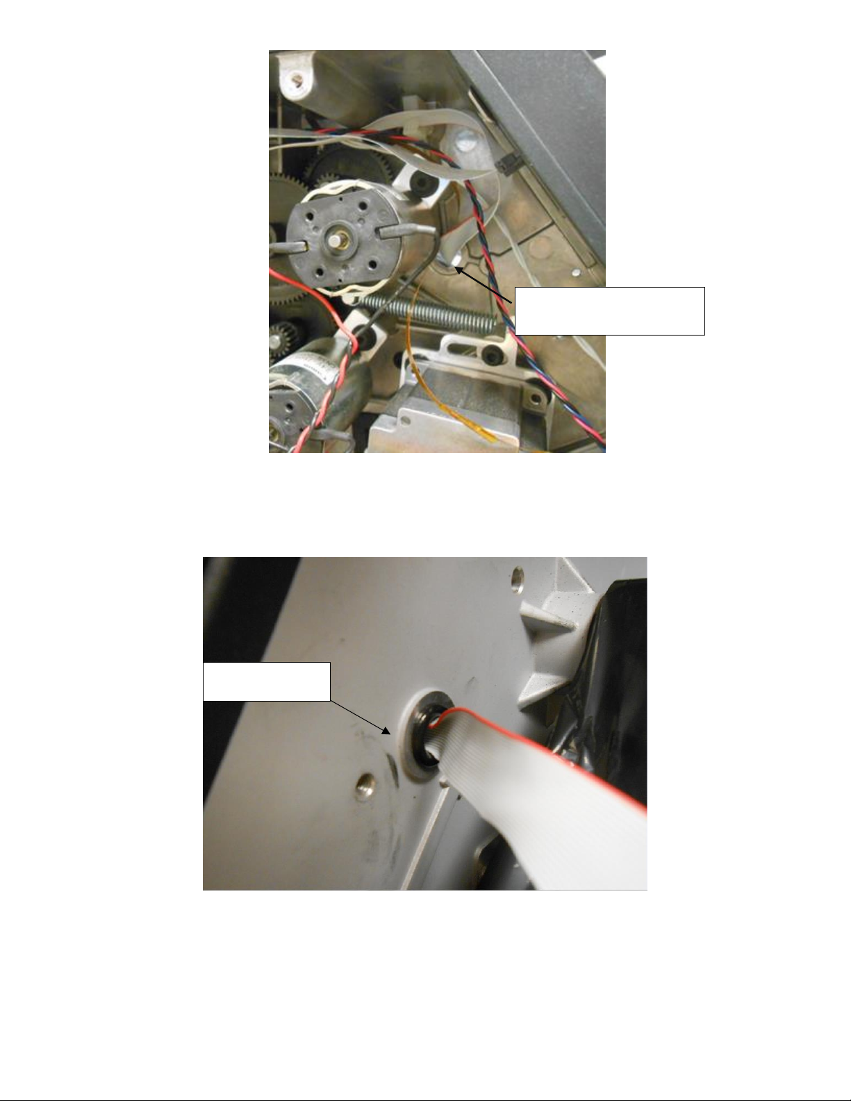
Split Grommet
Route ODV Data Cable
through Large Hole in Frame
Figure 10: Routing the Power/Data Cable through large hole in frame
10. Route the ODV Data Cable through large hole in frame next to ribbon motor.
11.
On the media side of the printer, install Split Grommet over ODV Power Data Cable. Squeeze and press into large
hole on frame.
Figure 11: Install Split Grommet
10
Page 11
5. Installing ODV2D-V2 and Mounting Bracket to Printer
Lock Levers
Power/Data Cable
M4x10mm Flanged
Mounting Screws (3)
IMPORTANT: The ODV2D-V2 unit comes with a protective plastic film over the scan glass to protect from finger
prints. Be sure this cover remains in place when handing the assembly. Do not remove it until
instructed later in this procedure.
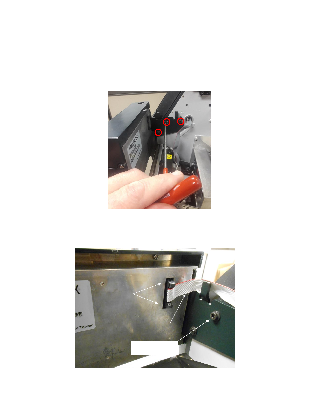
1. On the media side of the printer, hold the ODV2D-V2 using your left hand with your fingers under the top recessed
area at the back of the unit. Align the three holes on the mounting bracket with the threaded holes in the printer
frame. Thread the three M4x10mm flanged SHC screws provided and then use a 3mm hex key to firmly secure the
ODV bracket against the printer frame.
Figure 12: Installing the ODV2D-V2 w/Bracket to the Printer Frame
2. Plug the power/data ribbon flat cable into the connector at the back of the ODV.
NOTE: Be sure the plug is oriented the same direction as shown in Figure 12 and secure the plug using the connector
Lock Levers.
11
Page 12
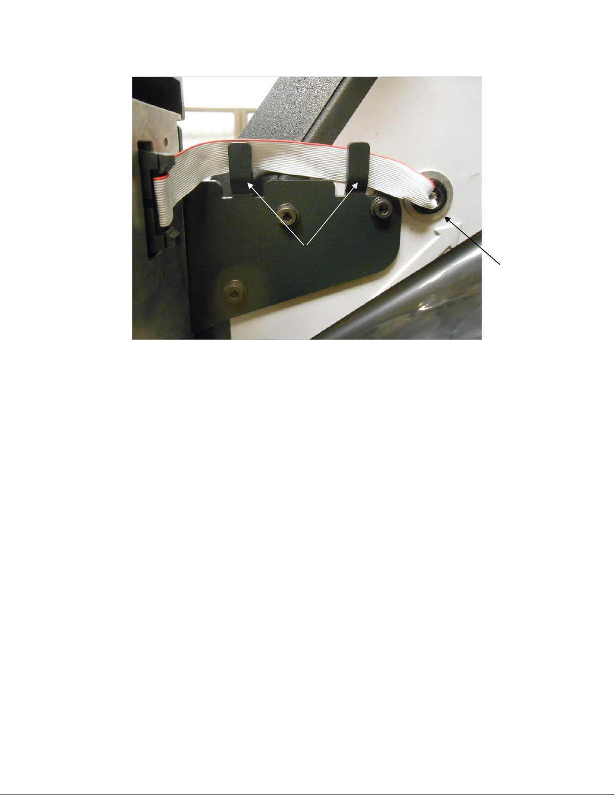
Figure 13: Plugging the Power/Data Cable into the ODV2D-V2
Split Grommet
ODV2D-V2 Bracket Tabs
Figure 14: Routing the Power/Data Cable on the Bracket and into the Frame Opening
3. Route the Power/Data cable between the printer frame and both ODV2D-V2 bracket tabs shown in Figure 14.
Make sure the cable is not pinched between the bracket and the frame.
12
Page 13
6. Coarse Mechanical Alignment
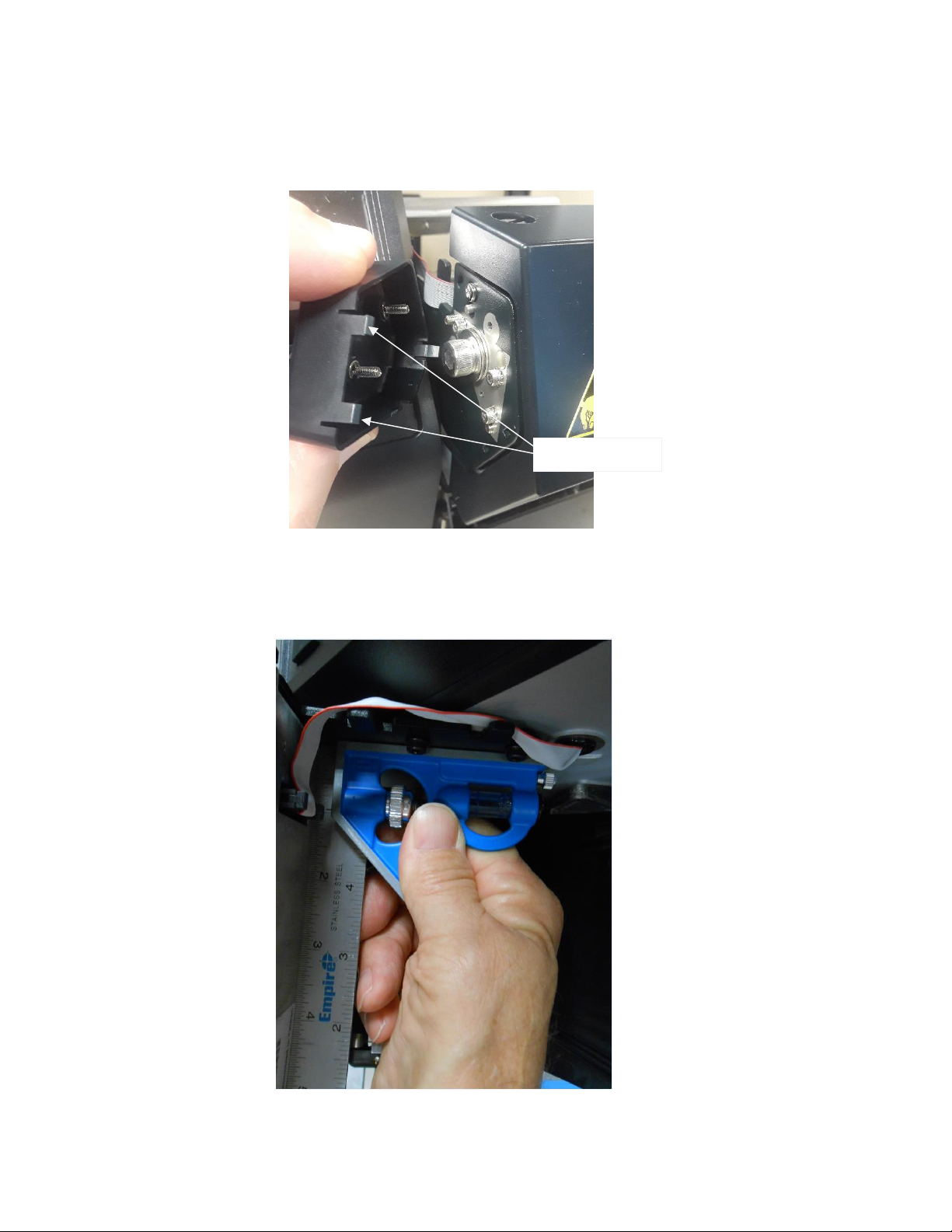
Locking Tabs (3)
1. Loosen the two captured screws securing the side plastic cover located on the inboard side of the ODV, then
squeeze the top and bottom of the cover to release its 3 locking tabs and remove the cover to access the locking
and adjustment screws. Set the cover aside.
Figure 15: Removing the Plastic Cover on the ODV2D-V2
2. Place a 6 inch square between the ODV2D-V2 and the mounting bracket to verify that the back of the ODV is at
an exact 90 degree angle with the ODV mounting bracket. There should be no gaps on either edge of the square.
Proceed to Step 3 if adjustment is needed.
Figure 16: Verifying a 90 Degree Angle Exists Between the ODV and Bracket
13
Page 14
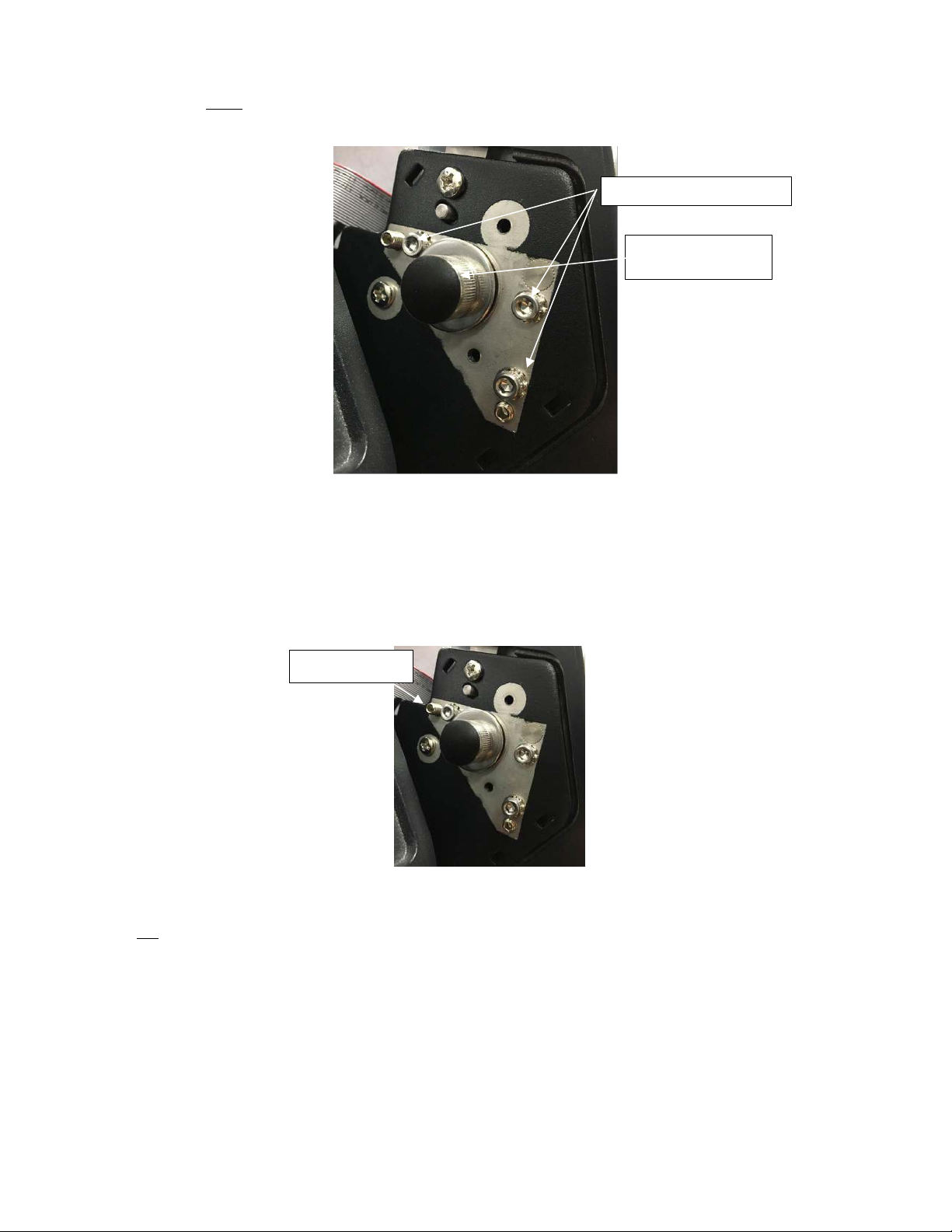
Small Locking Cap Screws
Setscrew ‘A’’
Large Cap Screw
DO NOT TOUCH
3. Loosen the 3 small Locking Cap Screws by turning each one 1/2 turn CCW (Counterclockwise) using a 2.5mm
hex key.
Figure 17: ODV2D-V2 Locking Screws
NOTE: The Large Cap Screw torque value is factory set. DO NOT TIGHTEN OR LOOSEN THIS SCREW. The screw
captures a compression spring that provides tension between the ODV2D and the mounting bracket, preventing
the ODV2D from moving freely when the small locking screws are loosened.
4. Then while holding the square in place (See Figure 16), adjust Setscrew ‘A’ CW using a 2mm hex key to move
the ODV2 forward or CCW to move it back until each edge of the square is flush against the ODV and the
mounting bracket.
Figure 18: ODV2D-V2 Adjustment Setscrew A
NOTE: Do not tighten any of the locking screws at this time. You will be instructed to do so in a later step.
14
Page 15
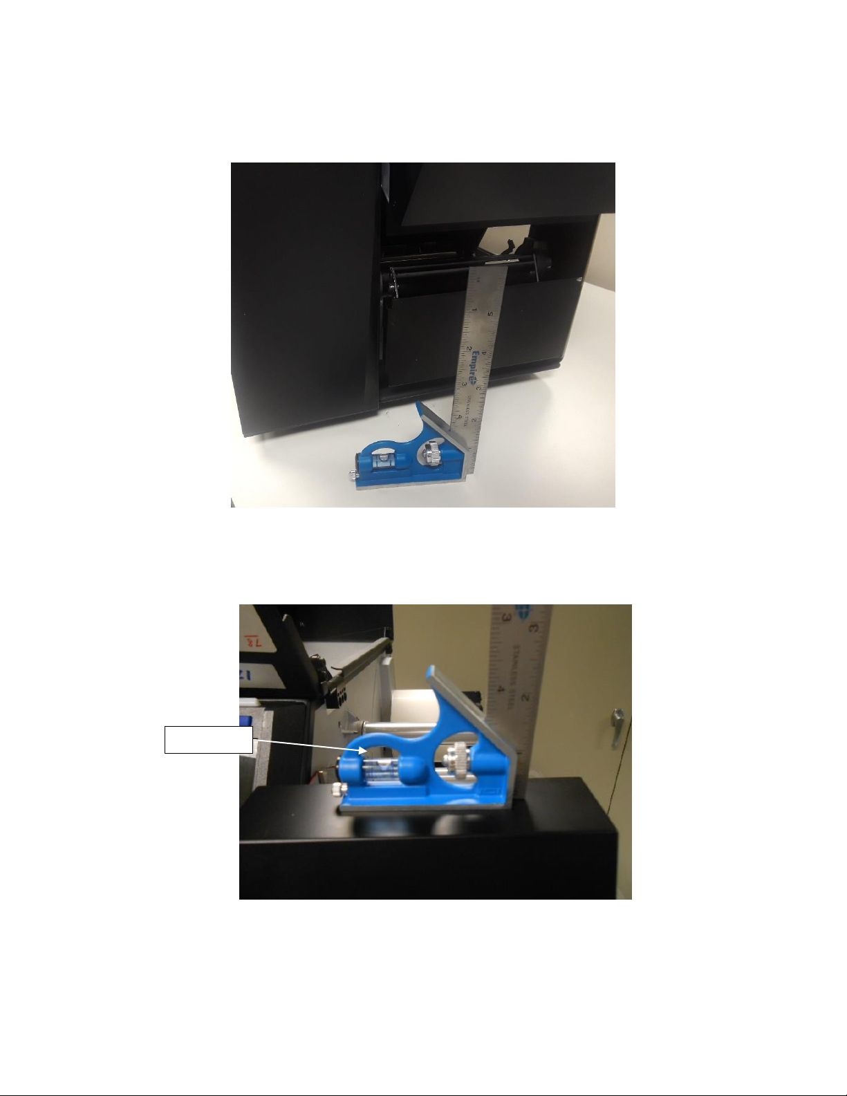
Bubble Level
5. Place the bubble level edge of the 6 inch square on the same flat surface that the printer is on and note the
position of the bubble.
Figure 19: Bubble Level Adjustment
NOTE: The bubble may NOT be centered in the level. It is not necessary that the table, the printer or the ODV2D be
perfectly level, only that the angles of these surfaces be match.
Figure 20: ODV2D-V2 Bubble Level Adjustment
6. Next rest the square on the top surface of the ODV2D-V2. The bubble should be at the same position as noted in
step 5.
15
Page 16
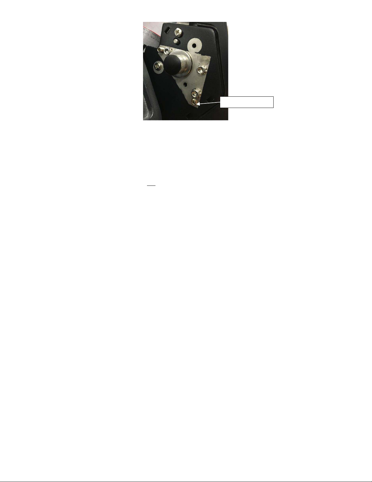
Setscrew ‘B’
Figure 21: ODV2D-V2 Level Adjustment Setscrew B
7. If ODV2D-V2 needs to be adjusted refer to Figure 20 and do the following: Use a 2mm hex key and turn
Setscrew ‘B’ CW to move the bubble to the right or CCW to move the bubble to the left.
NOTE: After leveling the ODV2D-V2, do not tighten any of the locking screws at this time. You will be instructed to
do so in a later step.
16
Page 17

7. Prepare for Alignment/Calibration
Figure 22: Power Cord, On/Off Switch location
1. Plug the power cord into the AC receptacle located on the rear of the printer.
2. Turn the power switch located on the rear of the printer ON (I) position.
Control Panel Special Key’s
The image below displays the names of the special key’s Soft Key #1 - Menu/Home, Enter/Navigation, Soft Key #2 Cancel/Back, PAUSE - Online/Offline and Feed keys.
Figure 23: Control Panel Special key’s
17
Page 18

Enable Validator
1. Press PAUSE key to take printer OFF-LINE.
2. Press UP and DOWN keys on control panel simultaneously and control will display:
“ATTENTION”
“ENTER SWITCH”
“ UNLOCKED“ OR “LOCKED”
If LOCKED then press both keys again to UNLOCK.
3. Press the ENTER key control panel will display .
4. Press the LEFT ARROW until .
5. Press the ENTER key and the control panel will display .
6. Press the ENTER key and the control panel will display .
7. Press the ENTER key and the control panel will display .
8. Press the DOWN key to select “Enable” .
9. Press the ENTER key to enter selection .
10. Press PAUSE key to take printer ON-LINE .
11. Press the ENTER key to save.
Viewing Printer / ODV2D-V2 Software Versions
NOTE: It is important to ensure that the printer and ODV2D-V2 have the latest software installed. Check with Printronix
Auto ID for current software revisions to be used. The following steps will show you how to check the software
versions in both printer and ODV2D-V2
Unlock Control Panel
1. Press PAUSE key to take printer OFF-LINE .
2. Press UP and DOWN keys on control panel simultaneously and control will display:
“ATTENTION”
“ENTER SWITCH”
“ UNLOCKED“ OR “LOCKED”
If LOCKED then press both keys again to UNLOCK.
18
Page 19

View Printer Software Version
1. Press PAUSE key to take printer OFF-LINE .
2. Press the right Soft Key #2 Cancel / Back, panel should display .
3. Press the RIGHT ARROW until Program File version and Part No. appear .
View ODV2D-V2 System / APP / DSP
1. Press the LEFT ARROW and DOWN keys until control panel displays ODV2D-V2 system
2. Press the LEFT Soft Key #1 Menu / Home to return to home menu .
3. Press PAUSE key to take printer ON-LINE .
4. Contact Printronix Auto ID for the latest Printer and ODV2D-V2 software versions needed for best performance.
Refer to the T8000 Administrator’s Manual for software download instructions.
Verifying T8 Printhead Element Functionality
IMPORTANT All T8 printhead elements must be functioning in order to support the ODV2D-V2 validator.
19
Page 20

1. Prior to doing the ODV2D Calibration Adjustments, enter the Tools menu and print a Grey test pattern to verify all
printhead elements are functioning correctly (no vertical white lines or voids).
2. Press PAUSE key to take printer OFF-LINE .
3. Press the ENTER key control panel will display, panel should display .
4. Press the right Soft Key #2 Cancel / Back, panel will display .
5. Press the RIGHT ARROW key until “Tools” have been selected .
6. Press the ENTER key control panel will display .
7. Press the ENTER key control panel will display .
8. Press the ENTER key control panel will display .
9. Press the DOWN key until “Grey” is selected .
10. Press the Press the ENTER key, and Grey test pattern will begin to print. To stop the printing press the
Press the ENTER key and printing will stop.
Figure 24: Grey Test Pattern
11. Press PAUSE key to take printer ON-LINE .
12. If white vertical lines or voids are present, use a Thermal Printer Cleaning Pen and thoroughly clean the brown
element area of the printhead, perform a re-test. If cleaning does not resolve voids or white lines during the retest, the printhead should be replaced.
20
Page 21

Removing Network Port Cover
Ethernet Port
ODV SD Card
1. Set the printer power switch to O (Off).
2. Use a 2.5mm hex key and loosen the two captured screws that secure the plastic cover on the right side of the
ODV and set the cover aside.
Figure 25: Removing the ODV2D-V2 Right Side Cover
Network Connection Type
Note: Refer to the ADDENDUM at end of this document for information on Dynamic or Static connection setup’s.
Dynamic Connection (DHCP)
1. Refer to “Dynamic Connection Ethernet Port” for Lap Top setup WITH ROUTER.
Static Connection
2. Refer to “Static Connection Ethernet Port” for Lap Top setup NO ROUTER.
3. Default IP Address 10.20.30.40
4. Plug an Ethernet CAT5 cable for the Dynamic connection, or an Ethernet crossover cable for the Static
connection into the port at the right side of the ODV2D-V2.
NOTE: A Crossover Cable for Ethernet is used to connect computing devices together directly. This type cable must be
used to connect the ODV2D-V2 directly to a laptop or PC when following the Static connection method.
21
Page 22

Ethernet Cable/Crossover
Cable to ODV
Figure 26: Plugging the Ethernet cable/crossover cable into the ODV2D-V2
Get ODV2D-V2’s IP Address
1. Press PAUSE key to take printer OFF-LINE, panel will display .
2. Press the Press the ENTER key control panel will display .
3. Press the LEFT ARROW until ODV2D-V2 .
4. Press the ENTER key control panel will display .
5. Press the DOWN key until “Statistics” is selected .
6. Press the ENTER key control panel will display .
7. Press the UP key until “IP Address” is selected .
8. Note the IP Address - it will be used later in ODV2D-V2 Calibration. Example 192.168.201.197.
9. Press PAUSE key to take printer ON-LINE, panel will display .
Preparing the T8X04 Prior to Printing the “Bullseye” Pattern
Ribbon:
Remove ribbon from the printer Take-up and Supply spindles if installed.
Media:
Install the 4”W x 6”L Direct Thermal fanfold media provided in the kit.
22
Page 23

T8x04 Mechanical Settings:
Head Pressure = 4
Pressure Block Settings on Pivoting Deck Scale – Left Block = 10cm, Right Block = 100cm
T8x04 Menu Option Settings:
Handling
Print Mode = Direct
1. Press PAUSE key to take printer OFF-LINE, panel will display .
2. Press the ENTER key control panel will display .
3. Press the left Soft Key #1 Menu/Home PREV .
4. Press the LEFT ARROW until Media .
5. Press the ENTER key control panel will display .
6. Press the DOWN key until “Handling” is selected .
7. Press the ENTER key control panel will display .
8. Press the ENTER key control panel will display
9. Press the DOWN key until “Direct” is selected .
10. Press the ENTER key control panel will display .
11. Press PAUSE key to continue .
Energy Star
Power Saver Active = Disable
12. Press the ENTER key control panel will display .
13. Press the RIGHT ARROW until “System” .
14. Press the ENTER key control panel will display .
23
Page 24

15. Press the DOWN to select “Energy Star” .
16. Press the ENTER key control panel will display .
17. Press the DOWN to select “PWR Saver Action” .
18. Press the ENTER key control panel will display .
19. Press the UP key until “Disable” is selected .
20. Press the ENTER key control panel will display .
21. Press the left Soft Key #1 Menu/Home to return to home menu .
22. Press PAUSE key take printer ON-LINE, panel will display .
23. Press the ENTER key control panel will display .
NOTE: Direct thermal mode will need to be changed back to Transfer when installation is complete.
24
Page 25

Print Speed Limits
The print speed limits of 2-10 IPS are based on steady paper motion and the ability of the ODV2D-V2 camera system to
gather and process the data effectively in real-time. No higher than 8 IPS is recommended.
Print Bullseye Pattern
Peel/Tear Door Assembly
IMPORTANT The door on the ODV2D-V2 Peel/Tear Door Assembly must be in the CLOSED position when doing
any Field Calibration adjustments using the “Bullseye” pattern.
Figure 27: Close Peel/Tear Door Assembly
Navigating Control Panel to Print “Bullseye”
Unlock Control Panel
1. Press PAUSE key to take printer OFF-LINE, panel will display .
Note: If C/P has been already un-locked, skip to Select “Bullseye” pattern now.
2. Press UP and DOWN keys on control panel simultaneously and control will display:
“ATTENTION”
“ENTER SWITCH”
“UNLOCKED“ OR “LOCKED”
If LOCKED, then press again to UNLOCK.
Select “Bullseye” Test Pattern
1. Press the ENTER key control panel will display .
2. Press RIGHT ARROW key until ODV2D-V2 menu is selected.
3. Press the ENTER key and the following will be displayed .
4. Press the DOWN key to select Diagnostic .
5. Press the ENTER key and the following will be displayed .
6. Press the DOWN key until “Print Bullseye” is selected .
25
Page 26

7. Press the ENTER key to print Bullseye as shown in figure 21 below.
NOTE: Reprint the “Bullseye” pattern if it printed over any part of the media liner gap.
Figure 28: “Bullseye” Pattern Printout
8. Tear off any extra labels. Leave only one label protruding from the printer exit.
Web Browsers
NOTE: Use the Chrome or Fire Fox web browser. IE may not work correctly.
1. Open the web browser and enter the ODV IP Address that was found in “Get ODV2D-V2s IP Address” in
previous steps.
Static IP Address
Dynamic IP Address
26
Page 27

8. Alignment
IMPORTANT: The ODV2D-V2 unit comes with a protective cover over the glass to protect from finger prints. Be
sure to remove it before starting the calibration process. Failure to do this will result in failure
during the calibration. Make sure the glass is clean before proceeding.
About Alignment
There are four inter-dependent mechanical adjustments that affect the alignment and calibration of the ODV2D: Height,
Tilt, Slope and Center-Line. They need to be set in the order shown.
The Height is factory set and should not need adjustment. Tilt and Slope are set independently, but may affect each other
(as one is changed, the other may move too) requiring an iterative adjustment. The Center-Line adjustment is done last.
Alignment Web Page
1. From ODV2D-V2 Dashboard, select Field Calibration.
NOTE: You may select which style ODV2D or ODV2D-V2 to be installed. The default web page is for the ODV2D-V2.
These installation instructions are for the ODV2D-V2 version. If you are installing an ODV2D, follow the on-screen
instructions for alignment and calibration.
Figure 29: Web Browser “ODV2D-V2 Dashboard”
27
Page 28

Figure 30: Web Browser “Field Calibration - Alignment”
Slope Adjustment Screw
Tilt Adjustment Screw
1. Select Alignment tab.
2. Press Calibration key.
1) Height Adjust
1. The height should not need adjustment, but if the dial is not in the “Green”, loosen the three M4 bracket
mounting screws and bias the ODV2D-V2 straight up or down in the mounting holes until the dial reaches the
“Green”. Be careful not to touch the scan glass as you grip the ODV2D-V2 assembly.
2. Re-tighten the three mounting screws. Confirm that the dial is in the “Green”.
3. If the dial is in the “Red”, contact Printronix Auto ID Customer Service for a replacement unit.
2) Slope Adjustment
Figure 31: Slope / Tilt Adjustment screws
28
Page 29

1. Adjust Slope setscrew to get the indicator into the “green”, as close to “0” as possible. The display on the web
page will indicate which direction to turn the screw.
Figure 32: Web Browser “Field Calibration, Target”
Figure 33: Slope / Tilt Dials
3) Tilt
1. For the Tilt adjustment, place the bubble level on the top of the ODV2D-V2 to make sure it is the same as
measured previously, and turn the setscrew so that it looks as straight as possible, while still keeping the dial in
the “green”. It may be necessary to return to the Slope setscrew, turning one, then the other to get them both into
the “green”.
29
Page 30

Small Locking Cap Screws
Figure 34: Tighten Mounting Screws
2. Slowly tighten the three small locking cap screws until secure, keeping both of the settings in the green. They do
not need to be perfectly aligned with the zero.
4) Center-Line Adjustment
Figure 35: Center-Line Adjustment
30
Page 31

Figure 36: Height / Center-Line Indicators
1. While looking at the Center-line Indicator on the web browser, use a flat blade driver, or a 3mm hex wrench, to
turn the Adjustment Screw on the top of the ODV2D per the “Right Hand Rule” – counter-clockwise turn, Centerline goes up. Clockwise turn, Center-line goes down, until the dial shows in the “Green”. It is not necessary to be
perfectly aligned with the zero.
Figure 37: Web Browser “Field Calibration, Target PASS”
31
Page 32

Save Button
Once the calibrations are complete, it is important to press the save button to set the center position to the correct
value. When performing label analysis and if the boxes are not aligned around the barcodes, this will be because of
not pressing the save button.
Tap Test
When unit is tight, and unit is still ON, tap on ODV unit and verify the dial gages all return into the green area.
32
Page 33

9. Calibration
Barcode Plaque
Calibration
White Gain
Calibration
Rmax= 89 Rmin = 3
Values (example)
Handle card here only
White Gain Calibration
Calibration Card
Figure 38: Calibration Card
Purpose:
1. The Calibration Card is used to ensure that the ODV2D-V2 is reporting reflectance values accurately.
When to use the Calibration Card:
2. Must be used when the ODV2D-V2 unit is first mounted on the printer.
3. Should be used if the printer is moved to a different lighting environment or there is a high barcode failure rate
noticed.
General Guidelines:
1. CLEAN !! CLEAN !! CLEAN !! It is important that the ODV2D-V2 glass is clean and free from fingerprints,
smudges, dust, and any debris in order to avoid calibrating the unit with imperfections on glass.
2. Printer cover should be down to reduce interference from ambient light.
3. Peel/Tear door must be open.
4. Only the Calibration Card should be placed in the scan line during calibration. Media should be removed from the
tear bar to prevent uneven calibration surface. Remove the ribbon if it is installed.
5. The Calibration Card should be kept clean from damage, scratches, smudges, dirt and other debris and should
always be stored in the plastic sleeve it was shipped in. Any Calibration Card that is dirty or damaged should not
be used and must be replaced.
6. The Calibration Card should only be handled by the edges, or the center section (“TOUCH HERE ONLY”)
Installing White Gain Calibration Card:
IMPORTANT The door on the ODV2D-V2 Peel/Tear Door Assembly must be in the open (down) position
1. Press the White Gain button.
2. With the white (no barcode) side of the card facing inward (see Figure 39), center the calibration card in the media
path and slide in until it stops.
33
Page 34

Figure 39: Install White Gain Calibration Card
Figure 40: White Gain Calibration Image Web Page
3. Press Setup Camera button. The following image should be displayed.
4. Press Calibrate button and the following message will be displayed.
34
Page 35

Figure 41: White Gain Calibration in progress message
5. When the White Gain Calibration is done, the following message will be displayed.
Figure 42: White Gain Calibration SUCCESS message
Reflectance Calibration
Installing Barcode Calibration card:
1. Press the Reflectance button.
Figure 43: Install Barcode Calibration Card
2. Install the barcode side of the calibration card facing inward, center the calibration card in the media path and slide in
until it stops.
Figure 44: Install Barcode Calibration Card
3. Press Setup button.
35
Page 36

4. Enter the Rmax and Rmin values located on the calibration card as shown below
Note: Values above are Example only. Your card will have it’s own value printed on it.
5. Press Calibrate button. The following message will be displayed.
Figure 45: Barcode Calibration in progress message
6. When the barcode calibration has finished, the following message will be displayed.
Figure 46: Barcode Calibration SUCCESS message
7. Power printer OFF / ON before performing the Functional Testing.
36
Page 37

10. Functional Testing
1. Power printer OFF / ON before performing the Functional Testing.
2. Make sure there is sufficient media installed to perform this test.
3. Close the Tear Bar Door.
2D Validation Demo Page
1. Press key to take printer OFF-LINE .
2. Press the key control panel will display, panel should display .
3. Press the key until “Tools” have been selected .
4. Press the key control panel will display .
5. Press the key control panel will display .
6. Press the key control panel will display .
7. Press the key until “Barcode Demo 2D” is selected .
8. Press the Press the key, and Barcode Demo 2D test pattern will begin to print a 1 Page 2D barcode image
and grade it.
NOTE: See (figure 40) below for screen image results.
Figure 47: Proper Rectangle Alignment Around Barcodes & Barcode Grades Image
37
Page 38

9. All grades must be an A or B.
10. Verify that the failure is not due to print quality, ribbon wrinkle, smudging or a bad ribbon. If the error is due to
poor print quality, correct the problem and try printing again.
Restoring the Printer Back to Normal Operation
1. Power Off the printer and remove the Ethernet cable from the right side of the ODV and remove any special
labels that were used to do the Field Calibration.
Install the required media and ribbon used to print labels and power On the printer. If required, configure the T8 to
print mode transfer, see below:
Handling
Print Mode = Transfer
2. Place the Peel/Tear door assembly in the operating (Up) position,
3. Reinstall the covers on the right and left sides of the ODV2D-V2.
4. Insert the plastic round cap into the center-line adjustment hole on the top of the ODV2D-V2.
38
Page 39

11. Options
Item
No.
PTX Part No.
Printronix Auto ID Description
1
P220348-001
Field Kit, Cutter,T8X04, ODV2D-V2
2
172444-001
Field Kit, Cutter Tray, 4in
3
P220338-901
Kit, Extended Media Cover
Item
No.
PTX Part No.
Printronix Auto ID Description
1
P200026-001
CABLE,RIBBON,0.05IN,20POS,22.00IN
2
P220141-001
PCBA,INTERTIE,ODV2D-V2
3
P220292-001
PLAQUE,CALIBRATION,ODV2D-V2
4
P220293-001
PEEL/TEAR ASSY,ODV2D-V2
5
P220287-001
ASSY,COVER,DUST,SD/RJ,ODV2D-V2
6
P220344-001
COVER,GIMBAL,ODV2D-V2
7
P220289-001
KIT,HARDWARE,ODV2D-V2
8
P220343-001
MOUNT BRACKET,MAIN,ODV2D-V2
9
P220283-001
RE-SHIP KIT,MODULE,ODV2D-V2
10
P220284-001
RESHIP KIT,4IN,T8000,ODV2D-V2
The following hardware options for the T8000 printer are compatible with the ODV2D-V2 assembly:
Make sure that the calibration routines are done with all options installed.
12. Maintenance
The ODV2D-V2 is a self-contained unit that requires only periodic cleaning. On every service call, power
down the printer and use Microfiber Glass and Mirror Cloth and Sight Savers Lens Cleaner Spray or
equivalent to clean the glass.
There are no serviceable parts within the ODV2D-V2 assembly. Replace any components that are
damaged or not operating per the spares list below:
13. Spare Parts
ODV2D-V2 Validator
Table 4. ODV2D-V2 Spares Parts List
39
Page 40

Table 5. Troubleshooting the Validator
Symptom
Solution
The ODV2D-V2 beam does not
come on.
1. Make sure the power/data cable is plugged
into the ODV2D-V2 and the controller board
on the printer.
2. Make sure the validator has not been disabled
in the ODV2D-V2 > Control > Validator Active
menu. See “Enable Validator” on page 15.
3. Print a bar code 2D Validation Demo page on
page 33.
4. Call your service representative if the problem
persists.
The ODV2D-V2 beam does not
cover the entire width of the
labels being printed.
There is something wrong with the LED array.
Call your service representative if the problem
persists.
The printer pauses after scanning
each label.
For complex labels with 2-D or several 1-D
barcodes, the printer might be waiting for the
ODV2D-V2 to complete analysis. Try reducing the
print speed to minimize pausing.
Printing less than 10 mil (0.010
inch) x-dimension width bar
codes constantly causes error
messages.
The validator does not recognize x-dimensions
smaller than10 mil. If you must print bar codes
this size, disable the validator to prevent error
reports. See “Enable Validator” on page 15.
The printed labels look clean, but
the validator is still reporting an
error message.
The validator glass may be dirty, distorting the
report results. Power down the printer and clean
the glass using Microfiber Glass and Mirror Cloth
and Sight Savers Lens Cleaner Spray or
equivalent.
14. Troubleshooting
If you are having problems with the validator, consult Table 5 for a list of symptoms and possible
solutions.
40
Page 41

Table 5. Troubleshooting the Validator
Symptom
Solution
The printed bar codes are
causing error conditions.
There are several factors which could be causing
validation errors:
• The ODV2D-V2 is not properly aligned with
the printer. See “Calibration” on page 22.
• The ODV2D-V2 White Gain / Reflectance may
need to be calibrated. Complete White Gain
calibration on page 29 and Reflectance on
page 32.
• Make sure the entire bar code passes
completely under the scanning beam.
• The validator and printer are not properly
communicating. Test the validator operation
without using a host. See 2D Validation Demo
page on page 33.
• Bar code width. The validator can recognize
x-dimensions as narrow as 10 mils.
• Bar code size. A minimum height of 0.10 inch
is required for validation. If problems persist,
increase the bar code height.
41
Page 42

Table 5. Troubleshooting the Validator
Symptom
Solution
The printed bar codes are
causing error conditions.
(continued)
• Bar code type. The validator only recognizes
the following linear, picket fence bar codes:
Codabar, Code 39, Code 93, Code 128,
Interleaved 2 of 5, and UPC/EAN, PDF417
and Data Matrix.
• Bar code spacing. The validator requires a
minimum distance of 1/2 inch or 20 times the
minimum element width, whichever is greater,
between bar codes.
Printer speed. See “
• Print Speed Limits” on page 22. If problems
persist, decrease the Media > Speed > Print
Speed.
• Be sure the bar code is not printing on the
extreme edges of the label.
• Clean the printhead. See “Cleaning” in the
Administrator’s Manual.
• Check that paper and ribbon are clean,
unwrinkled, and installed correctly.
• Check the number of bar codes being
validated concurrently. The validator can track
the performance of up to 50 barcodes at one
time.
If your application is not acting reliably, there are other possible factors including the reflectivity of the media and/or
ambient light affecting the camera’s ability to capture an image. Users should decrease the print speed in these situations
to see if this improves performance.
42
Page 43

ADDENDUM
Static Connection Ethernet Port
Note: All examples below are for the Windows 7 operating system.
Control Panel
Select Control Panel from START selection . The followig screen will be displayed.
Select “Network and Sharing Center” as shown above. And the following screen will be displayed.
43
Page 44

Select “Change Adapter settings” as shown above. The following screen should be displayed.
Select “Local Area Connection” as shown above. The following screen should be displayed.
44
Page 45

Select the “Properties” button as shown above. The following screen should be displayed.
Select “Internet Protocol Version 4(TCP / IPv4)” as shown above. The following screen should be displayed.
45
Page 46

Select “Use the following IP address” as shown above. The following screen will be displayed.
46
Page 47

Enter IP Address
Enter Subnet Mask
Enter Default Gateway
Press OK button when done.
Close all open windows.
This completes the configuration process.
Return to [ Preparing the T8X04 Prior to Printing the “Bullseye” Pattern ] now.
47
Page 48

Dynamic Connection Ethernet Port
Select Control Panel from START selection . The followig screen will be displayed.
Select “Network and Sharing Center” as shown above. And the following screen will be displayed.
Select “Change Adapter settings” as shown above. The following screen should be displayed.
48
Page 49

Select “Local Area Connection” as shown above. The following screen should be displayed.
Select the “Properties” button as shown above. The following screen should be displayed.
49
Page 50

Select “Internet Protocol Version 4(TCP / IPv4)” as shown above. The following screen should be displayed.
Select “Obtain an IP address automatically” as shown above. The following screen will be displayed.
Close all windows.
Return to [Preparing the T8X04 Prior to Printing the “Bullseye” Pattern] now.
50
Page 51

Contact Information
Americas
(844) 307-7120
Service@PrintronixAutoID.com
Europe, Middle East, and Africa
+31 (0) 24 3030 340
EMEA_support@PrintronixAutoID.com
Asia Pacific
+886 3 990 6155
APAC_support@PrintronixAutoID.com
China
+86 755 2398 0479
CHINA_support
@PrintronixAutoID.com
Printronix Customer Support Center
IMPORTANT Please have the following information available prior to calling the
Support Center:
• Model number
• Serial number (located on the back of the printer)
• Installed options (i.e., interface and host type if applicable to the problem)
• Configuration printout: Refer to the Administrator’s Manual.
• Is the problem with a new install or an existing printer?
• Description of the problem (be specific)
• Good and bad samples that clearly show the problem (faxing or emailing
may be required)
Printronix Customer
of these samples
Printronix Auto ID Support:
Printronix Auto ID Consumables: http://PrintronixAutoID.com/products/consumables/
http://PrintronixAutoID.com/support/
51
Page 52

Corporate Offices
Printronix Auto ID
3040 Saturn Street, Suite 200, Brea, CA
92821
U.S.A.
Phone: (844) 307-7120
Fax: (657) 258-0817
Printronix Auto ID,
Georg-Wimmer-Ring 8b D-85604 Zorneding
Germany
Phone: +49 (0) 8106 37979-23
Fax: +49 (0) 8106 37979-05
Printronix Auto ID, Asia Pacific Head Office
Taiwan
9F, No. 95, Minquan Rd.
Xindian Dist., New Taipei City
231 Taiwan (R.O.C)
Phone: +886 3 990 6155
Fax: +886 3 990 6215
Printronix Auto ID, China Head Office
Shenzhen
New World Center 2510 room
No. 6009, Yitian road
Futian District, Shenzhen
518000
China
EMEA Head Office
Phone: +86 755 2398 0479
Fax: +86 755 2398 0773
Visit the Printronix web site at
P180118-000 Rev B
www.PrintronixAutoID.com
52
 Loading...