

Page 1
15 Discovery Way, Acton, MA 01720
Phone: (978)263-3584, Fax: (978)263-5086
Web Site:
www.piacton.com
Operating Instructions
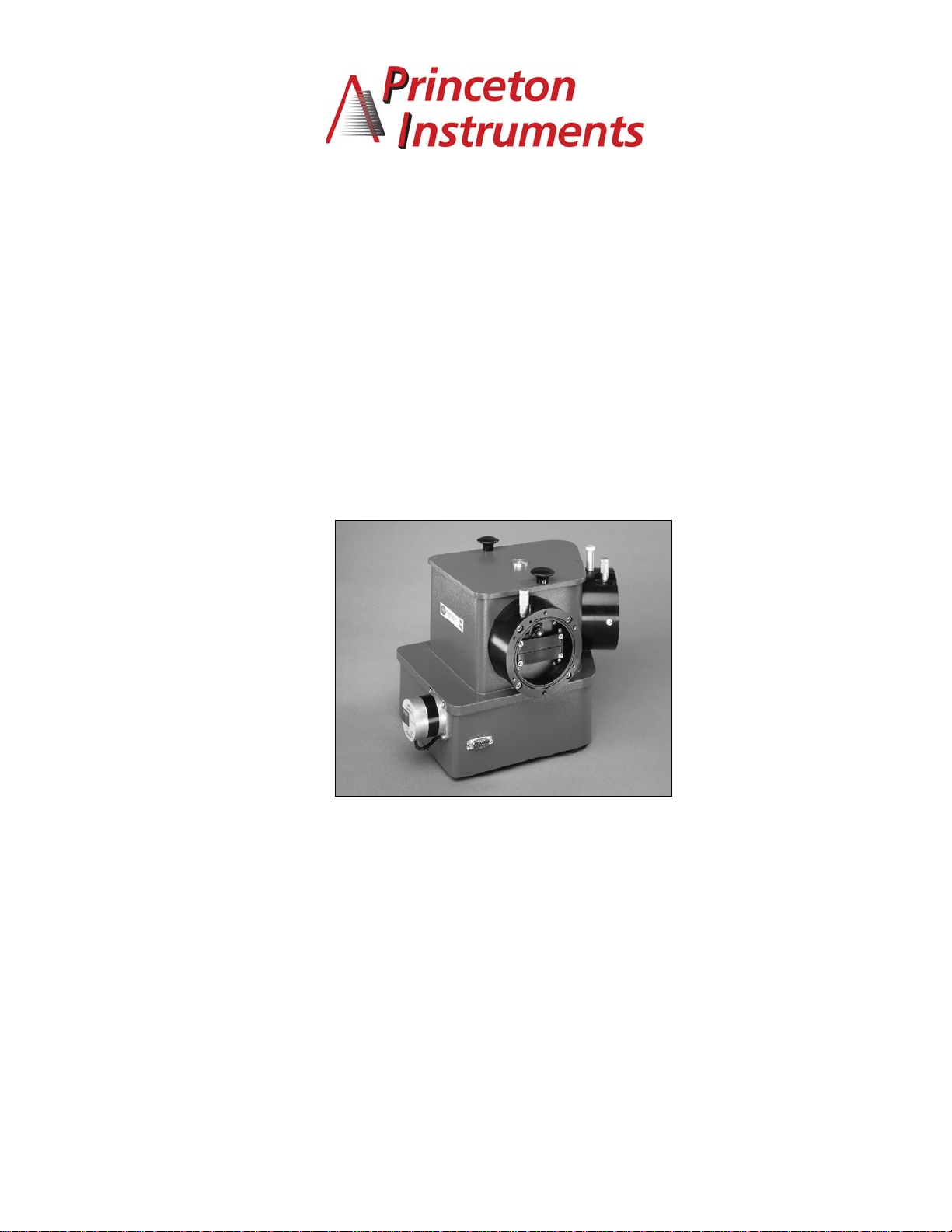
Princeton Instruments Model VM-502
0.2 Meter Vacuum Monochromator
VM-502 s/n: Rev. 5.0
SD3 s/n:
Page 2

PRINCETON INSTRUMENTS CORPORATION
VM-502
Operating Instructions
CONTENTS
Section I. General Description ................................................................................................1
1.1 Description.......................................................................................................................1
1.2 Specifications...................................................................................................................1
Section II. Instrument Setup....................................................................................................3
2.1 General Description: ........................................................................................................ 3
2.2 Unpacking and Inspection: ..............................................................................................3
2.3 Removal of Protective Cover and Shipping Ties:.............................................................3
2.4 Pumping System Mounting:.............................................................................................4
2.5 SD3 Connections:............................................................................................................4
2.6 Software Installation: .......................................................................................................6
2.7 System Operation ............................................................................................................7
Section III. Instrument Operation............................................................................................8
3.1 Bilateral Slit Assemblies: .................................................................................................8
3.2 Fixed Width Slit Assemblies: (optional)............................................................................8
3.3 Grating and Holder Assembly:.........................................................................................8
3.4 Air Inlet Valve: (optional).................................................................................................9
3.5 Movable Diverter Mirror: (optional) .................................................................................9
3.6 Slit Chamber Isolation Valves: (optional) ........................................................................9
3.7 Slit Chamber Air Inlet Valves: (optional) ........................................................................10
3.8 Slit Chamber Roughing Valves: (optional) .....................................................................10
Section IV. Controlling the VM-502 with the SD3 SpectraDrive Controller .......................11
4.1 Description..................................................................................................................... 11
4.2 Controlling the VM-502 Monochromator with Acton Software......... ............................... 11
4.3 Controlling the VM-502 Monochromator with User-Generated Software or LabVIEW...11
4.4 Controlling the VM-502 Monochromator at the Command Level ...................................11
Section V. Care of the Instrument......................................................................................... 16
5.1 Main Chamber (Instrument)...........................................................................................16
5.2 Bilateral Slits..................................................................................................................16
5.3 Scanning Mechanism ....................................................................................................16
5.4 Optical Surfaces ............................................................................................................16
Appendix A. Drawings and Schematics............................................................................... 17
VM-502 Pictorial................................................................................................................... 18
Pumping Port Size ...............................................................................................................19
Schematic (SpectraDrive Units only).................................................................................... 20
Page 3

Section I. General Description
1.1 Description
The Princeton Instruments Model VM-502 is a nominal 0.2 meter vacuum scanning
monochromator, with an optimum wavelength range in the vacuum ultraviolet region.
However, with other gratings and coatings, the instrument is useful from the extreme UV to
the infrared.
The Model VM-502 is designed to use an aberration-corrected concave holographic grating,
which provides and aperture ratio of f/4.5.
The Model VM-502 is set up as specified in the conventional “V” configuration (Model VM-502V), in a straight through configuration (Model VM-502-S), or a combination of both
(Model VM-502).
1.2 Specifications
Specifications are with standard 1200 G/mm gratings unless otherwise noted.
Focal Length: Nominal 0.2 meters
Optical System: Aberration-corrected concave holographic grating
Aperture Ratio: Nominal f/4.5
Reciprocal Linear Dispersion: Nominally 4.0 nm/mm, with 1200 G/mm grating in the first
order
Wavelength Range: Mechanical scanning range is zero order to 546.1 nm, with a 1200
G/mm grating. Low wavelength limit is dependent upon light source and detector; typically
less than 30 nm
Grating Coating: Standard coating is Princeton Instruments #1200 VUV Aluminum and MgF2,
with reflectance of 80% typical at 121.6 nm. Iridium coatings are optional for the extreme UV,
and are supplied if specified
Grating Holder: The grating holder is kinematically mounted in the instrument, allowing
gratings to be interchanged without requiring realignment. Each grating holder contains the
classical grating adjustments for initial alignment of the grating to the instrument
Scanning Mechanism: A sine drive mechanism provides a linear wavelength change with the
rotation of a precision lead screw. A Model SD3 controller is provided for scanning drive
control using a computer (customer provided).
Slits: Standard bilateral slits are supplied and are adjustable from 5 micrometers to 3
millimeters. A precision micrometer provides for slit adjustment under vacuum conditions, and
is graduated in 10 micrometer increments. The slit height is adjustable from 0 to 20 mm.
1
Page 4

If specified, standard fixed width slits 1m high are supplied to customer’s specified width.
Movable Diverter Mirror (optional): A movable diverter mirror is provided to divert the beam
from the V slit position to the straight through position. A knob in the instrument cover allows
the mirror to be moved under vacuum conditions
Slit Chamber Isolation Valve (optional): Vacuum valves are provided to isolate the slit
chambers form the main instrument chamber. Ports (1/8 NPT) are provided in the slit
chambers for gauge and roughing accessories
Air Inlet Valve (optional): An air inlet valve is located in the instrument housing to vent the
instrument to atmospheric pressure.
2
Page 5

Section II.
Instrument
2.1 General Description:
The instrument is shipped completely assembled, tested and ready for immediate installation. If
the instrument is to be stored before use, contact Princeton Instruments for storage instructions.
For shipping purposes, some optical components are covered, and mechanical components
are tied or placed in specific positions. The following procedure is recommended to prepare
the instrument for use.
2.2 Unpacking and Inspection:
Carefully unpack and examine both the VM-502 monochromator and the scan controller
unit. If there is any indication of physical damage, report the condition immediately to
the carrier and Princeton Instruments. Save all packing material.
2.3 Removal of Protective Cover and Shipping Ties:
To remove the protective cover on the optical component and the shipping tie, the instrument
must be vented and the cover removed. This should be done only by personnel familiar with
optical surfaces and instrumentation.
Setup
1. Locate the air inlet valve in the instrument housing. Remove the protective cap.
Connect the air inlet valve to a dry nitrogen tank if possible. Open the air inlet valve
slowly by rotating the handle until it is in line with the valve body.
2. Remove the instrument cover by rotating the two cover knobs until they are loose, and
lift off the cover.
--------------------------------------------------------------------------------------------------------------------CAUTION: THE OPTICAL SURFACE IS NOW EXPOSED--DO NOT TOUCH, TALK, OR
BREATHE OVER THE OPTICAL SURFACES!
---------------------------------------------------------------------------------------------------------------------
3. If the instrument is equipped with a movable diverter mirror, it is held in position with
rubber bands for shipment. Locate the rubber bands holding the movable diverter
mirror in position; cut and remove these rubber bands.
4. A protective cover is attached to the grating mask with rubber bands. Verify that all
rubber bands are removed from the chamber. Remove the shipping grating cover.
NOTE: Save this cover to protect the grating if interchanging gratings.
5. Replace the instrument cover after checking the o-ring and mating surface for
cleanliness.
NOTE: If the instrument has a movable diverter mirror, make sure that the diverter
mirror and the control knob on the cover align before replacing the instrument cover.
Refer to Section 3.5 for more information
6. Close the air inlet valve by rotating the handle 90º to the valve body.
3
Page 6
2.4 Pumping System Mounting:
The instrument is now ready for mounting to a pumping system. The VM-502 and Pumping
Port Size drawings (pages 18 and 19, respectively) show the location and dimensions of a
pumping port in the instrument base. The instrument may be supported by the pumping port or
by the three pads provided.
--------------------------------------------------------------------------------------------------------------------------CAUTION: DO NOT APPLY EXCESS PRESSURE BETWEEN THE PUMPING PORT AND
THE THREE PADS PROVIDED ON THE BASE OF THE INSTRUMENT!
---------------------------------------------------------------------------------------------------------------------------
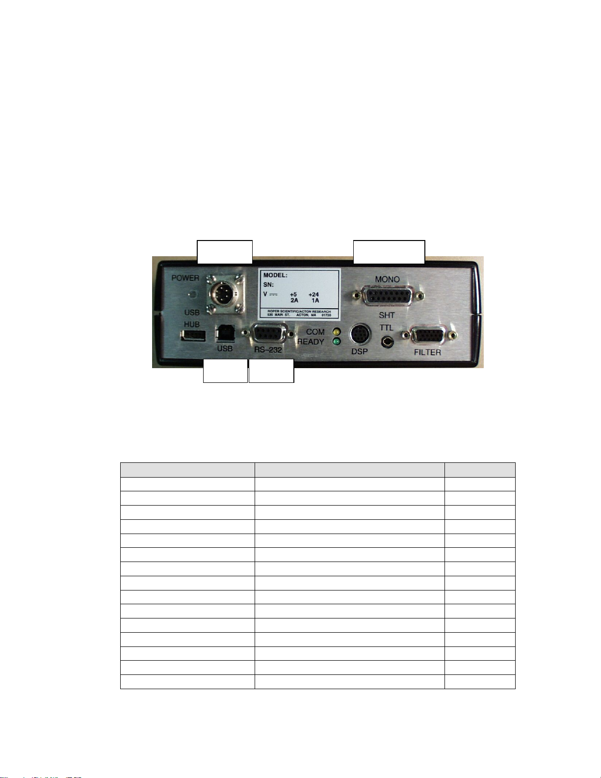
2.5 SD3 Connections:
The figure below shows the cable connections necessary for operation from a computer
through the RS-232 or USB port.
Power
Connection
USB
Interface
RS-232
Interface
Monochromator
Connection
1. Locate the SD3 controller, two interconnecting cables, the power supply and power
cable.
2. Connect the motor drive cable between the 15 pin D connector (J1) on the
monochromator and the 15 pin D connector (MONO) on the SD3-502.
Pin #-Monochromator Description Pin #-SD3
1 Motor – A1 1
2 Motor – A2 2
3 Motor – B1 3
4 Motor – B2 4
5 Open 5
6 Shield–(Controller Only) 6
7 Interrupt Module +5V 7
8 Interrupt Module GND 8
9 Interrupt Module 1 LED K 9
10 Interrupt Module 2 LED K 10
11 Interrupt Module 1 LED A 11
12 Interrupt Module 1 OUT WORM 12
13 Interrupt Module 2 LED A 13
14 Interrupt Module 2 OUT MOTOR 14
15 Open
4
Table 1: J1 - Motor Drive Connector at Monochromator and SD3-502
Page 7
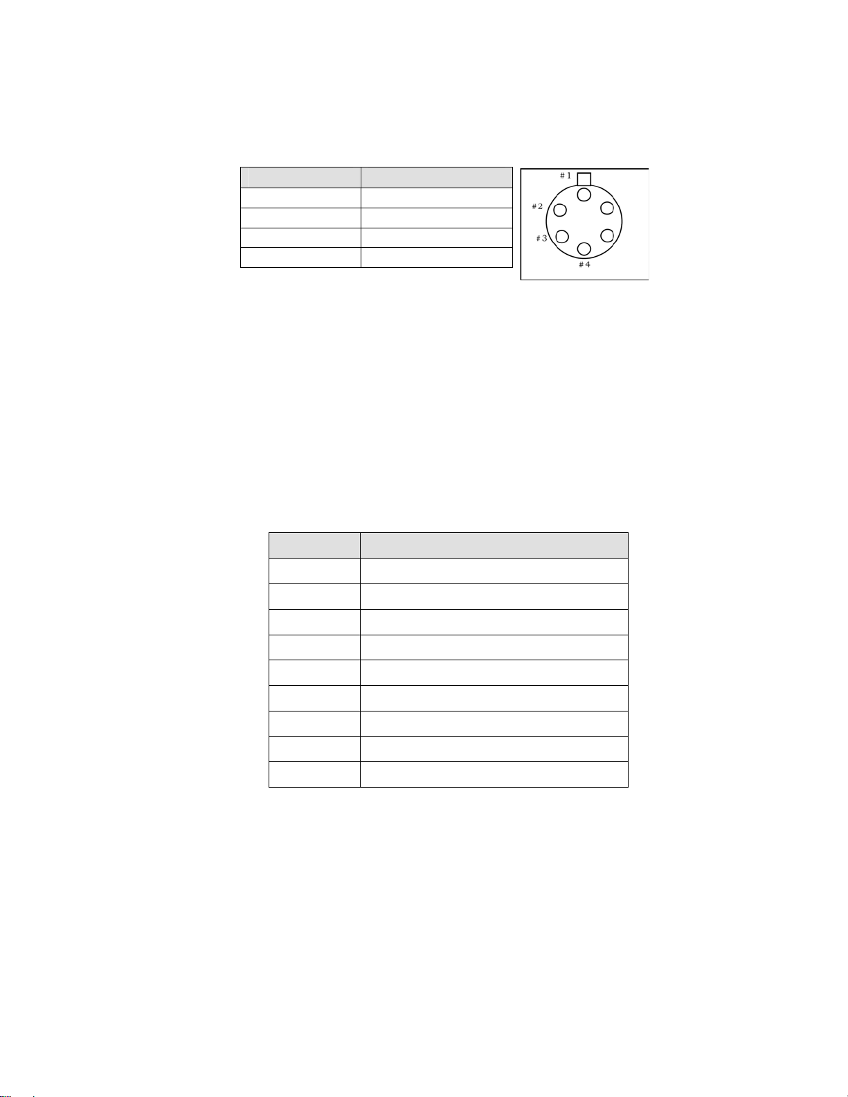
3. Make sure that power supply is switched OFF and connect it to POWER connector on
the SD3. Connect the line cord provided with the SD3 to the power supply and the AC
line. The power supply will operate with line voltages between 100 and 250 volts AC
50/60 Hz and provides +5 volts DC for the SD3 control logic and +24 volts DC for the
motor drives.
Pin # Description
1 +5V
2 GND
3 GND
4 +24V
Table 2: Power Input Pin Arrangement:
4. Connect the SD3 to a computer.
Computer: Use one of the two-supplied computer cables:
RS-232 IBM PC or compatible 9-pin female (DB9S) connector to 9-pin male
connector ( DB9P).
USB USB Cable Type A to Type B.
NOTE: If neither of these cables is compatible with your system, consult Princeton
Instruments for a custom cable. If you have facilities for constructing a custom cable,
use the RS232 pin arrangement shown in Table 3.
Pin # Description
1 open
2 RD data from SD3 to computer
3 TD data from computer to SD3
4 open
5 ground
6 open
7 RTS
8 CTS
9 open
Table 3: RS232 Computer Interface Pin Arrangement:
5. For RS232 communication, set up the terminal or RS232 computer port as follows:
9600 baud, 8 data bits, no parity, 1 start bit, 1 stop bit.
5
Page 8

2.6 Software Installation:
Each VM-502 monochromator ships with the Actono Monochromator Control Software CD
CD. If you have not purchased Princeton Instruments' SpectraSense or WinSpec/32 software,
use this CD to install the Monochromator Control Software on your computer. The following
instructions briefly describe the installation process. For greater detail, refer to the
Monochromator Control Software manual on the CD.
1. Locate your Monochromator Control Software CD.
2. Exit any programs you are running to avoid conflicts during the installation.
3. Insert the CD. Windows should automatically detect the autostart program and begin
the installation process. If it does not, click on the Start button and go up to Run. Click
on the Browse button, find the directory that contains Autorun.exe, and then click on
Open. Click on OK.
4. Install Acton Control.
5. After the installation is complete, restart your computer.
If you have received SpectraSense and are planning to use it to control the system, the
following instructions briefly describe the software installation process. For greater detail, refer
to the SpectraSense manual on the CD.
1. Locate the SpectraSense Software CD (it is not necessary to install the Monochromator
Control Software since it has been incorporated into the SpectraSense software).
2. Exit any programs you are running to avoid conflicts during the installation.
3. Place the SpectraSense CD-ROM in the drive. Click on the Start button, go up to Run.
Click on the Browse button and find the drive and directory that contains Autorun.exe.
Click on Autorun.exe and then Open. Click on OK.
4. An installation panel will appear. Click on the install button that is appropriate for your
operating system.
5. Follow the directions on the screen to complete the installation.
6. After the installation is complete, restart your computer.
If you will be using Princeton Instruments WinSpec/32 software, the following instructions
briefly describe the software installation process. For greater detail, refer to the WinSpec
and the Monochromator Control Software manuals.
1. Locate your WinSpec/32 CD and your Monochromator Control Software CD.
2. To avoid conflicts during the installation, exit any programs you are running.
3. Insert the WinSpec/32 CD. Windows should detect the autostart program and begin the
installation process.
4. Click on the program you want to install. In most cases, this will be WinSpec/32.
5. When asked, choose “AutoPCI” as the communications type.
6. After the installation is complete, restart your computer.
7. After restart, insert the Mono Control Software CD and install the monochromator
control software.
8. After the installation is complete, restart the computer.
6
Page 9

2.7 System Operation
It is important that the VM-502 be connected to the computer and be initialized before the
controlling software is started.
If the VM-502 is part of a system that includes a Princeton Instruments SpectraHub
Detector Interface and a single point detector such as a PMT or a Silicon Diode detector,
then the entire system will be controlled through the Princeton Instruments SpectraSense
software. The software automatically detects the VM-502 and sets up all necessary
parameters for its operation.
If the VM-502 is part of a system that includes a Princeton Instruments CCD camera,
the system is then controlled either through SpectraSense software mentioned above
or through Princeton Instruments WinSpec software. If using WinSpec, you must set
up the Spectrograph parameters by selecting AM505 in "Define Spectrograph" and by
setting the focal length to 200 mm, the included angle to 64 degrees and the detector
angle to 32.5 degrees in calibration. Follow the instructions in the WinSpec manual for
CCD calibration.
Now that you have completed the hardware and software installations, refer to
Instrument Operation
for information about operating, adjusting, or changing various VM-502
Section III.
hardware assemblies and components. See Section IV. Controlling the VM-502 with the SD3
SpectraDrive Controller
and the Monochromator Control Software for software-control
information. For additional information about maintaining the VM-502, see Section V Care of
the Instrument
.
7
Page 10

3.1 Bilateral Slit Assemblies:
Section III.
Instrument
Operation
1. Slit
2. Slit
3. Optional Adapters are available for use with Princeton Instruments CCD Cameras. Cameras
Width: The slit width of each bilateral slit assembly is adjustable from 0.005 millimeters
to 3 millimeters (5 to 3,000 micrometers) by a micrometer knob located on the slit housing.
The micrometer knob is graduated in 0.01 millimeter (10 micrometer) increments.
One counterclockwise revolution of the micrometer knob increases the slit width 0.25
millimeters (250 micrometers). For maximum reproducibility, the slit width should be set in
a counterclockwise direction (increasing slit widths) each time it is changed.
The micrometer knob should not be rotated below a reading 0.00 or above a reading of
3.00. A micrometer setting of less than 0.005 millimeters (5 micrometers) cannot be used,
because a stop is provided to prevent the slit jaws from touching each other.
Height: The slit height is controlled by a pair of horizontal baffles located in the slit
housing, and must be set up prior to mounting a pair of graduated blocks, located in the slit
housing. The graduations on the blocks are 1 mm apart, with the center graduation being
the widest. To adjust the baffles, loosen the screws at each end of the horizontal baffles,
loosen the screws at each end of the horizontal baffle and set the baffles to 1/2 the total
desired slit height above and below the center graduation.
are available that will allow operation down to the VM-502 lower wavelength limit of 3 0 nm.
NOTE: In most optical systems, resolution deteriorates with increasing slit height;
therefore, if maximum resolution is required, slits of one to four millimeters should be used.
3.2 Fixed Width Slit Assemblies: (optional)
Slit apertures 1 cm high and with a fixed width are provided. The width of each slit is marked
on each fixed slit assembly. The fixed slit assemblies are removable from the slit housing and
are precisely aligned to a master slit for each interchange and precise alignment.
3.3 Grating and Holder Assembly:
The grating holder assembly is kinematically mounted onto a rotary table in the instrument
vacuum chamber. Therefore, after initial alignment, the assembly can be removed and
replaced without alignment.
To remove the grating holder assembly from the instrument, the following procedure is
recommended:
1. Make sure that the instrument is at atmospheric pressure.
2. Remove the instrument cover by rotating the two cover knobs counterclockwise until the
screws are loose. Remove the cover.
---------------------------------------------------------------------------------------------------------------------
CAUTION: THE GRATING IS NOW EXPOSED--DO NOT TOUCH, TALK, OR
BREATHE ON THE GRATING!
---------------------------------------------------------------------------------------------------------------------
8
Page 11

3. Place the shipping grating cover supplied over the face of the grating. Loosen the one
8-32 clamp screw in the base of the grating assembly and remove the
complete grating holder assembly.
Reverse the procedure when reinstalling the grating assembly.
NOTE: To ensure proper positioning, make sure that the grating assembly is properly seated
before tightening the 8-32 clamp screw. The clamp screw should be tightened the same
torque to ensure proper positioning.
-----------------------------------------------------------------------------------------------------------------------------CAUTION: If the instrument has a movable diverter mirror, make sure that the diverter mirror
and the control knob on the cover align before replacing the instrument cover. Refer to
Section 3.5 for more information.
------------------------------------------------------------------------------------------------------------------------------
3.4 Air Inlet Valve: (optional)
An air inlet valve is supplied to bring the main instrument chamber to atmospheric pressure,
and is located in the instrument housing. The valve is open when the handle is in line with the
valve body, and closed when the handle is at 90º to the valve body.
--------------------------------------------------------------------------------------------------------CAUTION: Make sure that the vacuum system is in the proper mode
before opening air inlet valve!
---------------------------------------------------------------------------------------------------------
3.5 Movable Diverter Mirror: (optional)
A movable diverter mirror diverts the beam from the “V” slit position to the straight through slit
position. A knob on the instrument cover indexes the mirror to either the “S” or “V” position.
The “V” position, positions the mirror out of the beam, and the “S” position diverts the beam to
the straight through slit position. To change the mirror position, gently rotate the knob to the
desired “S” or “V” position; a click will be heard and felt when the mirror indexes into position.
NOTE: When the instrument cover is replaced, make sure that the diverter mirror and its
control knob are set to the same “S” or “V” position for proper engagement of the mirror and
knob control arm.
3.6 Slit Chamber Isolation Valves: (optional)
Vacuum valves are located in the slit housing to isolate the slit chamber from the main
instrument chamber. A valve control knob is located on the top of each slit housing. The valve
is open when the knob is in line with the optical beam and closed when the knob is in line with
the silver dot on the slit housing. (approximately 80 degrees to the beam).
--------------------------------------------------------------------------------------------------------------------CAUTION: Never vent the main instrument chamber with the slit chamber isolation valves
closed. Never open the slit chamber isolation valve with the main instrument chamber under
vacuum and the slit chambers at atmospheric pressure. When the main instrument chamber is
under vacuum, the slit chambers must be evacuated to 200 Torr or less before the slit
chamber isolation valves can be opened.
---------------------------------------------------------------------------------------------------------------------
9
Page 12

3.7 Slit Chamber Air Inlet Valves: (optional)
An air inlet valve is supplied to bring the slit chamber to atmospheric pressure and is located
on the side of the slit housing. The valve is open when the handle is in line with the valve
body, and closed when the handle is 90 degrees to the valve body.
--------------------------------------------------------------------------------------------------------------------CAUTION: Make sure that the isolation valve is closed
before opening slit chamber air inlet valve!
---------------------------------------------------------------------------------------------------------------------
3.8 Slit Chamber Roughing Valves: (optional)
A slit chamber roughing valve is supplied for connection to an auxiliary mechanical pump for
rough pumping of the slit chamber. The valve is open when the handle is in line with the valve
body, and closed when the handle is 90 degrees to the valve body.
---------------------------------------------------------------------------------------------------------------------
CAUTION: Make sure that the isolation valve and the air inlet valve are closed
before opening roughing valve!
---------------------------------------------------------------------------------------------------------------------
10
Page 13

Section IV.
Controlling
4.1 Description
The Princeton Instruments SD3 SpectraDrive Controller is used with the Acton
VM Monochromators in conjunction with Acton Monochromator Control
Software to provide the electronic drive for wavelength positioning, diverter mirror control and
filter positioning. The SD3 also provides the link between the monochromator and the
computer. Both USB and RS-232 are supplied as standard interfaces.
4.2 Controlling the VM-502 Monochromator with Acton Software
The Monochromator Control Software is normally installed in the directory C:\Program
Files\Acton. This directory contains the subdirectory Bin. The Bin directory contains the
executable code. There will normally be a Acton icon on the desktop that can be used
for starting the software. If this icon is not on the desktop, go to the Acton Bin directory
and start the software. When the Monochromator Control software loads, there is a main
screen with selections for operating the monochromator and various setup functions. Click on
the Operation box and a screen will come up which allows for basic control of the
monochromator wavelength. All functions of this software are described in the Monochromator
Control Software manual supplied on the Monochromator Control Software install CD.
4.3 Controlling the VM-502 Monochromator with User-Generated Software or LabVIEW
the VM-502 with the SD3 SpectraDrive Controller
The Monochromator Control Software install disk contains a folder named Acton_SDK.
This folder contains DLLs with example code in Delphi, Visual Basic, C++ and LabVIEW as
well as a folder with examples for use of the COM interface.
4.4 Controlling the VM-502 Monochromator at the Command Level
Although it requires more programming on the user’s part, the SD3 can also be controlled with
direct commands through its USB port or RS-232 port. The same command set, listed below,
is used for both RS232 and USB.
Commands can be sent as single commands or grouped in strings of commands. All
commands are single words (contain no spaces) and all commands in a string are separated
by at least one space. Parameters, if needed, precede the command and are separated from
the command by at least one space (e.g. 546.7 GOTO).
For RS232 operation, the port setup is 9600 baud, 8 data bits, 1 stop bit and no parity. A
convenient tool for trying out this mode of operation is the program HyperTerminal supplied
with the Windows operating system. The USB port with the driver supplied also shows up as
and is treated like a com port – although a very fast one. All commands or strings of
commands must be terminated with a carriage return (0D hex). The SD3 responds to a
command when the command has been completed by returning the characters OK followed by
carriage return and line feed (hex ASCII sequence 20 6F 6B 0D 0A). The default condition is to
echo each character that is sent to the SD3 with the RS-232 interface and to not echo the
commands when using the USB interface. When sending a command or string of commands,
it is important to wait for the SD3 to complete the processing of that command string before
sending another command.
11
Page 14

Monochromator Wavelength Movement Commands
GOTO
Goes to a destination wavelength at maximum motor speed. Accepts
destination wavelength in nm as a floating point number with up to 4
digits after the decimal point or whole number wavelength with no
decimal point.
<GOTO>
NM
<NM>
>NM
?NM
MONO-?DONE
MONO-STOP
Same as GOTO (For compatibility with software written for previous Acton
models.)
Goes to a destination wavelength at constant nm/min rate specified by
last NM/MIN command. Accepts destination wavelength in nm as a
floating point number with up to 4 digits after the decimal point or
whole number wavelength with no decimal point.
Same as NM (For compatibility with software written for previous Acton
models.)
Similar to NM except it returns control to user immediately rather than
waiting for Completion of monochromator wavelength move. Can be
used with? NM or MONO-?DONE below. This command must be
terminated with MONO-STOP listed below. NOTE: Use the NM
command when communication with the monochromator during the
scan is not required.
Returns present wavelength in nm to 0.01 nm resolution with units nm
appended. e.g. ?NM 300.00 nm
Used with >NM command to determine if monochromator has reached
the destination. Returns 0 if move is not complete, 1 if move is
complete.
Stops the monochromator wavelength move after use of the >NM
command.
NM/MIN
Sets constant scan rate in nm/min to 0.01 nm/min resolution. e.g. 10.0
NM/MIN
?NM/MIN
Returns present scan rate in nm/min to 0.01 nm/min resolution with
units nm/min appended. e.g. ?NM/MIN 100.00 nm/min
Grating Control Commands:
NOTE: These Grating Control Commands are used for all Acton series Monochromators. The
VM-502 has a limited selection of concave gratings. When manually changing gratings, it is
necessary to also select the grating number in Monochromator Control software,
SpectraSense, or WinSpec to allow the correct grating parameters to be used.
GRATING
Recalls parameters for the specified grating from non-volatile memory.
Up to nine (9) gratings are allowed. This command takes a grating
number from 1 - 9. e.g. 3 GRATING
?GRATING
?GRATINGS
Returns the number of the grating presently being used numbered 1-9.
Returns the list of installed gratings with position, groove density and
blaze. The present grating is specified with an arrow.
12
Page 15

The following command is used for grating installation by Acton part #:
INSTALL
Installs new grating parameters into the non-volatile memory of the
monochromator. Uses the part # of the grating to specify the
parameters.
e.g. 1-120-500 5 INSTALL places a 1200 g/mm grating blazed at
500 nm into the second grating position on #5.
The following commands are used for grating installation by grating parameters:
SELECT-GRATING
G/MM
Specifies the grating number to be installed 1 - 9.
Specifies groove density of grating to be installed in g/mm.
e.g. 1200 G/MM
BLAZE
Specifies the blaze wavelength and units of the grating to be installed
with 7 characters of the user’s choice. Unlike other commands, this
command is issued before the parameters. After the command is
issued, the SD3 responds with “ “ . Seven characters are then entered
(these may be numbers, letters, spaces or special characters).
UNINSTALL
Used to remove a grating and its parameters from the SD3 non-volatile
memory e.g. 3 UNINSTALL
13
Page 16

Calibration Commands:
INIT-OFFSET
Sets the offset value for the designated grating. Default
values are 25600 for all gratings. The grating designator
used with this command is grating# - 1.
e.g. 25590. 0 INIT-OFFSET for setting offset on grating #1.
NOTE: This command requires a decimal point after the
offset value.
For the new parameters of this command to take effect, the
monochromator must be initialized with the MONO-RESET
command or by turning the power off and back on.
INIT-GADJUST
MONO-EESTATUS
RESTORE
FACTORY
SETTINGS
MONO-RESET
Sets grating adjustment value for the designated grating.
Default values are 10000 for all gratings. The limits on the
parameter for this command are +/- 1000 for all gratings.
The grating designator used with this command is the
grating # - 1.
e.g. 9993 1 INIT-GADJUST for setting gadjust on the
second grating.
NOTE: No decimal point is used with this command. For the
new parameters of this command to take effect, the
monochromator must be initialized with the MONO-RESET
command or by turning the power off and back on.
Returns setup and grating calibration parameters for all
gratings.
Returns all parameters including grating calibration
parameters to the original factory calibrated settings.
NOTE: This command will overwrite any calibration
parameters set by the user.
Initializes the monochromator. Necessary after using INIT-
OFFSET or INIT-GADJUST.
HELLO
MODEL
SERIAL
14
Same as MONO-RESET. Used to maintain compatibility
with existing applications.
Returns model number of the monochromator.
e.g. MODEL VM-502
Returns serial number of the monochromator.
e.g. SERIAL 37480263
Page 17

The following are the Start-Up parameters and their default values:
Default Values:
GRATING #1
WAVELENGTH 0.0 nm
SCAN SPEED
INIT-
WAVELENGTH
INIT-SRATE
200.0 nm/min
Sets an initial wavelength for the SD3 after initialization.
e.g. 435.84 INIT-WAVELENGTH
Sets an initial scan rate for the SD3.
e.g. 200.0 INIT-SRATE
15
Page 18

Section V.
Care
5.1 Main Chamber (Instrument)
The main chamber should be kept sealed at all times, and under vacuum if possible. Only
vacuum-compatible material should be exposed to the vacuum of the instrument. When
operating the instrument in the vacuum ultraviolet region, the vacuum should be better than 5 x
-5
10
Torr.
5.2 Bilateral Slits
The knife edges that form the slit aperture are mounted on Ball Slides and therefore require no
lubrication. Nothing should contact the slit jaws directly; the slides are spring-loaded to
prevent damage, thus their positions can be changed if they are contacted directly.
5.3 Scanning Mechanism
The precision drive screw is located in the instrument base and should be lubricated every 6
months with the oil supplied.
5.4 Optical Surfaces
of the Instrument
The optical surfaces are extremely delicate and can be permanently damaged by mechanical
contact with anything. Do not touch, talk or breathe over the optical surfaces. After long
periods of use, the optical surfaces become contaminated and therefore have a drastically
reduced efficiency. Princeton Instruments can generally re-coat the optical components and
obtain their original efficiency, depending of course on the condition of the surfaces. Please
contact Princeton Instruments directly if you believe the optical surfaces are contaminated
or damaged.
16
Page 19

Appendix A.
Drawings
and Schematics
17
Page 20

Page 21

Page 22

 Loading...