

Page 1
ProEM-HS
Camera System
4411-0149
Issue 2
July 6, 2015
Page 2

Revision History
Issue Date List of Changes
Issue 2 July 6, 2015 Issue 2 of this document incorporates the following changes:
• Added ProEM-HS: 1024BX3
• General cleanup and document reorganization.
Issue 1 December 11, 2014 This is the initial release of this document.
Copyright 2014-2015 Princeton Instruments, a division of Roper Scientific, Inc.
3660 Quakerbridge Rd
Trenton, NJ 08619
TEL: 800-874-9789 / 609-587-9797
FAX: 609-587-1970
All rights reserved. No part of this publication may be reproduced by any means without the written permission of Princeton
Instruments, a division of Roper Scientific, Inc. (“Princeton Instruments”).
Printed in the United States of America.
BASE, IntelliCal, OptiCAL, PICam, PINS, and Unichrome are trademarks of Roper Scientific, Inc.
eXcelon, LightField, ProEM, and PVCAM are registered trademarks of Roper Scientific, Inc.
Intel is a registered trademark of Intel Corporation or its subsidiaries in the United States and other countries.
LabVIEW is a registered trademark of National Instruments, Inc.
LEMO is a registered trademark of INTERLEMO HOLDING SA
Scientific Imaging ToolKit and SITK are trademarks of R Cubed Software Consultants, LLC.
Windows and Windows Vista are registered trademarks of Microsoft Corporation in the United States and/or other countries.
The information in this publication is believed to be accurate as of the publication release date. However, Princeton Instruments does
not assume any responsibility for any consequences including any damages resulting from the use thereof. The information contained
herein is subject to change without notice. Revision of this publication may be issued to incorporate such change.
Page 3

Table of Contents
Chapter 1: About this Document . . . . . . . . . . . . . . . . . . . . . . . . . . . . . . . . . . . 11
1.1 Intended Audience. . . . . . . . . . . . . . . . . . . . . . . . . . . . . . . . . . . . . . . . . . . . . . . . . . . .11
1.2 Related Documentation . . . . . . . . . . . . . . . . . . . . . . . . . . . . . . . . . . . . . . . . . . . . . . . .11
1.3 Document Organization . . . . . . . . . . . . . . . . . . . . . . . . . . . . . . . . . . . . . . . . . . . . . . .12
1.4 Conventions. . . . . . . . . . . . . . . . . . . . . . . . . . . . . . . . . . . . . . . . . . . . . . . . . . . . . . . . .13
1.5 Safety Information. . . . . . . . . . . . . . . . . . . . . . . . . . . . . . . . . . . . . . . . . . . . . . . . . . . .14
1.5.1 Safety Related Symbols Used in this Manual . . . . . . . . . . . . . . . . . . . . . . . . .14
1.6 Precautions . . . . . . . . . . . . . . . . . . . . . . . . . . . . . . . . . . . . . . . . . . . . . . . . . . . . . . . . .15
1.6.1 UV Coating . . . . . . . . . . . . . . . . . . . . . . . . . . . . . . . . . . . . . . . . . . . . . . . . . . .15
Chapter 2: ProEM-HS Camera System . . . . . . . . . . . . . . . . . . . . . . . . . . . . . . 17
2.1 ProEM-HS Camera . . . . . . . . . . . . . . . . . . . . . . . . . . . . . . . . . . . . . . . . . . . . . . . . . . .18
2.1.1 EMCCD Technology and On-Chip Multiplication Gain . . . . . . . . . . . . . . . .18
2.1.2 Integrated Controller . . . . . . . . . . . . . . . . . . . . . . . . . . . . . . . . . . . . . . . . . . . .19
2.1.3 Power. . . . . . . . . . . . . . . . . . . . . . . . . . . . . . . . . . . . . . . . . . . . . . . . . . . . . . . .19
2.1.4 CCD Arrays . . . . . . . . . . . . . . . . . . . . . . . . . . . . . . . . . . . . . . . . . . . . . . . . . . .19
2.1.5 Cooling . . . . . . . . . . . . . . . . . . . . . . . . . . . . . . . . . . . . . . . . . . . . . . . . . . . . . .20
2.1.5.1 Internal Fan . . . . . . . . . . . . . . . . . . . . . . . . . . . . . . . . . . . . . . . . . . . .20
2.1.5.2 External Cooling Circulator . . . . . . . . . . . . . . . . . . . . . . . . . . . . . . .20
2.1.5.3 Coolant Ports. . . . . . . . . . . . . . . . . . . . . . . . . . . . . . . . . . . . . . . . . . .20
2.1.6 Rear-Panel Connectors . . . . . . . . . . . . . . . . . . . . . . . . . . . . . . . . . . . . . . . . . .21
2.2 Cables . . . . . . . . . . . . . . . . . . . . . . . . . . . . . . . . . . . . . . . . . . . . . . . . . . . . . . . . . . . . .22
2.3 Certificate of Performance . . . . . . . . . . . . . . . . . . . . . . . . . . . . . . . . . . . . . . . . . . . . .23
2.4 ProEM-HS System User Manual . . . . . . . . . . . . . . . . . . . . . . . . . . . . . . . . . . . . . . . .23
2.5 Application Software. . . . . . . . . . . . . . . . . . . . . . . . . . . . . . . . . . . . . . . . . . . . . . . . . .23
2.6 Minimum Host Computer Specifications . . . . . . . . . . . . . . . . . . . . . . . . . . . . . . . . . .25
2.6.1 LightField Requirements. . . . . . . . . . . . . . . . . . . . . . . . . . . . . . . . . . . . . . . . .25
2.6.2 WinX Requirements . . . . . . . . . . . . . . . . . . . . . . . . . . . . . . . . . . . . . . . . . . . .25
2.7 Accessories . . . . . . . . . . . . . . . . . . . . . . . . . . . . . . . . . . . . . . . . . . . . . . . . . . . . . . . . .26
2.7.1 CoolCUBE
2.7.2 Spectroscopy Mounts . . . . . . . . . . . . . . . . . . . . . . . . . . . . . . . . . . . . . . . . . . .27
2.8 ProEM-HS Camera and System Maintenance . . . . . . . . . . . . . . . . . . . . . . . . . . . . . .28
2.8.1 Camera. . . . . . . . . . . . . . . . . . . . . . . . . . . . . . . . . . . . . . . . . . . . . . . . . . . . . . .28
2.8.2 Optical Surfaces. . . . . . . . . . . . . . . . . . . . . . . . . . . . . . . . . . . . . . . . . . . . . . . .28
2.8.3 Repairs. . . . . . . . . . . . . . . . . . . . . . . . . . . . . . . . . . . . . . . . . . . . . . . . . . . . . . .28
Coolant Circulator . . . . . . . . . . . . . . . . . . . . . . . . . . . . . . . . . . .26
II
Chapter 3: System Installation. . . . . . . . . . . . . . . . . . . . . . . . . . . . . . . . . . . . . 29
3.1 System Configuration Diagrams . . . . . . . . . . . . . . . . . . . . . . . . . . . . . . . . . . . . . . . . .30
Page 4

4 ProEM-HS User Manual Issue 2
Chapter 4: System Setup. . . . . . . . . . . . . . . . . . . . . . . . . . . . . . . . . . . . . . . . . . 33
4.1 Unpack the System . . . . . . . . . . . . . . . . . . . . . . . . . . . . . . . . . . . . . . . . . . . . . . . . . . 33
4.2 Verify Equipment and Parts Inventory . . . . . . . . . . . . . . . . . . . . . . . . . . . . . . . . . . . 34
4.3 Attaching a Lens to a C-Mount Adapter . . . . . . . . . . . . . . . . . . . . . . . . . . . . . . . . . . 34
4.3.1 Mounting the Lens . . . . . . . . . . . . . . . . . . . . . . . . . . . . . . . . . . . . . . . . . . . . . 35
4.3.2 Adjusting the C-Mount Adapter. . . . . . . . . . . . . . . . . . . . . . . . . . . . . . . . . . . 35
4.4 Mounting the Adjustable C- to Spectroscopy-Mount Adapter . . . . . . . . . . . . . . . . . 36
4.4.1 Procedure . . . . . . . . . . . . . . . . . . . . . . . . . . . . . . . . . . . . . . . . . . . . . . . . . . . . 37
4.5 Positioning ProEM-HS Masks. . . . . . . . . . . . . . . . . . . . . . . . . . . . . . . . . . . . . . . . . . 38
4.6 Opening/Closing ProEM-HS Manual Shutter . . . . . . . . . . . . . . . . . . . . . . . . . . . . . . 39
4.7 Connect a CoolCUBEII Circulator . . . . . . . . . . . . . . . . . . . . . . . . . . . . . . . . . . . . . . 39
4.8 Application Software Installation . . . . . . . . . . . . . . . . . . . . . . . . . . . . . . . . . . . . . . . 40
4.8.1 LightField. . . . . . . . . . . . . . . . . . . . . . . . . . . . . . . . . . . . . . . . . . . . . . . . . . . . 40
4.8.2 WinX Application . . . . . . . . . . . . . . . . . . . . . . . . . . . . . . . . . . . . . . . . . . . . . 42
4.9 Configure Default Camera System Parameters . . . . . . . . . . . . . . . . . . . . . . . . . . . . . 43
4.9.1 LightField. . . . . . . . . . . . . . . . . . . . . . . . . . . . . . . . . . . . . . . . . . . . . . . . . . . . 43
4.9.2 WinX (Versions 2.6.10 or later). . . . . . . . . . . . . . . . . . . . . . . . . . . . . . . . . . . 44
Chapter 5: LightField First Light. . . . . . . . . . . . . . . . . . . . . . . . . . . . . . . . . . . . 45
5.1 Imaging Applications. . . . . . . . . . . . . . . . . . . . . . . . . . . . . . . . . . . . . . . . . . . . . . . . . 47
5.1.1 System Set Up and Configuration . . . . . . . . . . . . . . . . . . . . . . . . . . . . . . . . . 47
5.1.2 Data Acquisition. . . . . . . . . . . . . . . . . . . . . . . . . . . . . . . . . . . . . . . . . . . . . . . 49
5.2 Spectroscopy . . . . . . . . . . . . . . . . . . . . . . . . . . . . . . . . . . . . . . . . . . . . . . . . . . . . . . . 51
5.2.1 System Set Up and Configuration . . . . . . . . . . . . . . . . . . . . . . . . . . . . . . . . . 52
5.2.2 Rotational Alignment and Focus . . . . . . . . . . . . . . . . . . . . . . . . . . . . . . . . . . 54
5.2.2.1 Acton Series Spectrograph . . . . . . . . . . . . . . . . . . . . . . . . . . . . . . . 55
5.2.2.2 IsoPlane SCT-320 Spectrograph . . . . . . . . . . . . . . . . . . . . . . . . . . . 58
5.2.3 Data Acquisition. . . . . . . . . . . . . . . . . . . . . . . . . . . . . . . . . . . . . . . . . . . . . . . 59
5.3 System Shutdown. . . . . . . . . . . . . . . . . . . . . . . . . . . . . . . . . . . . . . . . . . . . . . . . . . . . 59
Chapter 6: WinX/32 First Light . . . . . . . . . . . . . . . . . . . . . . . . . . . . . . . . . . . . . 61
6.1 Power On Sequencing . . . . . . . . . . . . . . . . . . . . . . . . . . . . . . . . . . . . . . . . . . . . . . . . 62
6.2 Imaging Applications. . . . . . . . . . . . . . . . . . . . . . . . . . . . . . . . . . . . . . . . . . . . . . . . . 63
6.2.1 Equipment Setup . . . . . . . . . . . . . . . . . . . . . . . . . . . . . . . . . . . . . . . . . . . . . . 63
6.2.2 Configure ProEM-HS Parameters . . . . . . . . . . . . . . . . . . . . . . . . . . . . . . . . . 64
6.2.3 Focus the System . . . . . . . . . . . . . . . . . . . . . . . . . . . . . . . . . . . . . . . . . . . . . . 67
6.2.4 Acquire Data . . . . . . . . . . . . . . . . . . . . . . . . . . . . . . . . . . . . . . . . . . . . . . . . . 67
6.3 Spectroscopy Applications. . . . . . . . . . . . . . . . . . . . . . . . . . . . . . . . . . . . . . . . . . . . . 68
6.3.1 Equipment Setup . . . . . . . . . . . . . . . . . . . . . . . . . . . . . . . . . . . . . . . . . . . . . . 69
6.3.2 Configure ProEM-HS Parameters . . . . . . . . . . . . . . . . . . . . . . . . . . . . . . . . . 69
6.3.3 Configure Spectrograph Parameters . . . . . . . . . . . . . . . . . . . . . . . . . . . . . . . 73
6.3.4 Verify Shutter Operation . . . . . . . . . . . . . . . . . . . . . . . . . . . . . . . . . . . . . . . . 74
6.3.5 Rotational Alignment. . . . . . . . . . . . . . . . . . . . . . . . . . . . . . . . . . . . . . . . . . . 75
6.3.5.1 Acton Series Spectrograph . . . . . . . . . . . . . . . . . . . . . . . . . . . . . . . 76
6.3.5.2 IsoPlane SCT-320 Spectrograph . . . . . . . . . . . . . . . . . . . . . . . . . . . 77
6.3.6 Focus the System . . . . . . . . . . . . . . . . . . . . . . . . . . . . . . . . . . . . . . . . . . . . . . 78
6.3.6.1 Acton Series Spectrograph . . . . . . . . . . . . . . . . . . . . . . . . . . . . . . . 79
6.3.6.2 IsoPlane SCT-320 Spectrograph . . . . . . . . . . . . . . . . . . . . . . . . . . . 79
6.3.7 Data Acquisition. . . . . . . . . . . . . . . . . . . . . . . . . . . . . . . . . . . . . . . . . . . . . . . 80
6.4 Power Down Sequencing. . . . . . . . . . . . . . . . . . . . . . . . . . . . . . . . . . . . . . . . . . . . . . 80
Page 5

Table of Contents 5
Chapter 7: Exposure and Signal . . . . . . . . . . . . . . . . . . . . . . . . . . . . . . . . . . . 81
7.1 Exposure Time . . . . . . . . . . . . . . . . . . . . . . . . . . . . . . . . . . . . . . . . . . . . . . . . . . . . . .81
7.2 Avalanche Gain {EM Gain} . . . . . . . . . . . . . . . . . . . . . . . . . . . . . . . . . . . . . . . . . . . .82
7.3 EM Gain Calibration . . . . . . . . . . . . . . . . . . . . . . . . . . . . . . . . . . . . . . . . . . . . . . . . . .83
7.4 CCD Temperature . . . . . . . . . . . . . . . . . . . . . . . . . . . . . . . . . . . . . . . . . . . . . . . . . . . .84
7.5 Dark Charge . . . . . . . . . . . . . . . . . . . . . . . . . . . . . . . . . . . . . . . . . . . . . . . . . . . . . . . .85
7.6 Bias Active Stabilization Engine (BASE™). . . . . . . . . . . . . . . . . . . . . . . . . . . . . . . .85
7.7 Clock Induced Charge (CIC). . . . . . . . . . . . . . . . . . . . . . . . . . . . . . . . . . . . . . . . . . . .85
7.8 Saturation. . . . . . . . . . . . . . . . . . . . . . . . . . . . . . . . . . . . . . . . . . . . . . . . . . . . . . . . . . .86
7.9 Cleaning. . . . . . . . . . . . . . . . . . . . . . . . . . . . . . . . . . . . . . . . . . . . . . . . . . . . . . . . . . . .87
7.10 Readout . . . . . . . . . . . . . . . . . . . . . . . . . . . . . . . . . . . . . . . . . . . . . . . . . . . . . . . . . . . .89
7.10.1 Dual-Readout Port Operation . . . . . . . . . . . . . . . . . . . . . . . . . . . . . . . . . . . . .90
7.10.2 Controller Gain {Analog Gain}. . . . . . . . . . . . . . . . . . . . . . . . . . . . . . . . . . . .91
7.10.3 Readout Rate . . . . . . . . . . . . . . . . . . . . . . . . . . . . . . . . . . . . . . . . . . . . . . . . . .92
7.10.4 Regions of Interest (ROI) . . . . . . . . . . . . . . . . . . . . . . . . . . . . . . . . . . . . . . . .92
7.10.4.1 LightField . . . . . . . . . . . . . . . . . . . . . . . . . . . . . . . . . . . . . . . . . . . . .93
7.10.4.2 WinX/32 . . . . . . . . . . . . . . . . . . . . . . . . . . . . . . . . . . . . . . . . . . . . . .93
7.10.4.3 WinX/32 Examples . . . . . . . . . . . . . . . . . . . . . . . . . . . . . . . . . . . . . .93
7.10.5 Binning . . . . . . . . . . . . . . . . . . . . . . . . . . . . . . . . . . . . . . . . . . . . . . . . . . . . . .94
7.10.5.1 Array Orientation . . . . . . . . . . . . . . . . . . . . . . . . . . . . . . . . . . . . . . .94
7.10.6 Exposure - Readout Modes . . . . . . . . . . . . . . . . . . . . . . . . . . . . . . . . . . . . . . .95
7.10.6.1 Frame Transfer Mode (Simultaneous Exposure-Readout) . . . . . . . .95
7.10.6.2 Full Frame (Sequential) Mode for Frame-Transfer EMCCD . . . . . .98
7.10.6.3 Full Frame Readout for Full Frame EMCCD . . . . . . . . . . . . . . . . . .99
7.10.7 Readout Time . . . . . . . . . . . . . . . . . . . . . . . . . . . . . . . . . . . . . . . . . . . . . . . .100
Chapter 8: Experiment Synchronization . . . . . . . . . . . . . . . . . . . . . . . . . . . . 101
8.1 Shutter Control Mode . . . . . . . . . . . . . . . . . . . . . . . . . . . . . . . . . . . . . . . . . . . . . . . .101
8.2 Timing Mode. . . . . . . . . . . . . . . . . . . . . . . . . . . . . . . . . . . . . . . . . . . . . . . . . . . . . . .102
8.2.1 Free Run {No Response} . . . . . . . . . . . . . . . . . . . . . . . . . . . . . . . . . . . . . . .102
8.2.2 External Sync {Readout Per Trigger} . . . . . . . . . . . . . . . . . . . . . . . . . . . . . .103
8.2.3 Bulb Trigger {Expose During Trigger Pulse} Timing . . . . . . . . . . . . . . . . .104
8.2.4 Trigger Start {Start On Single Trigger} . . . . . . . . . . . . . . . . . . . . . . . . . . . .105
8.3 Fast and Safe Modes . . . . . . . . . . . . . . . . . . . . . . . . . . . . . . . . . . . . . . . . . . . . . . . . .105
8.3.1 Fast Mode (LightField and WinX/32). . . . . . . . . . . . . . . . . . . . . . . . . . . . . .105
8.3.2 Safe Mode (WinX/32) . . . . . . . . . . . . . . . . . . . . . . . . . . . . . . . . . . . . . . . . . .107
8.4 LOGIC OUT Control . . . . . . . . . . . . . . . . . . . . . . . . . . . . . . . . . . . . . . . . . . . . . . . .107
Chapter 9: Kinetics Mode . . . . . . . . . . . . . . . . . . . . . . . . . . . . . . . . . . . . . . . . 109
9.1 Kinetics Readout . . . . . . . . . . . . . . . . . . . . . . . . . . . . . . . . . . . . . . . . . . . . . . . . . . . .110
9.2 Timing Modes and Shutter Control. . . . . . . . . . . . . . . . . . . . . . . . . . . . . . . . . . . . . .113
9.3 Triggered Operation . . . . . . . . . . . . . . . . . . . . . . . . . . . . . . . . . . . . . . . . . . . . . . . . .113
9.4 Cleaning the CCD . . . . . . . . . . . . . . . . . . . . . . . . . . . . . . . . . . . . . . . . . . . . . . . . . . .115
9.5 Configure a Kinetics Experiment . . . . . . . . . . . . . . . . . . . . . . . . . . . . . . . . . . . . . . .115
9.5.1 Configure LightField. . . . . . . . . . . . . . . . . . . . . . . . . . . . . . . . . . . . . . . . . . .116
9.5.2 Configure WinX/32 . . . . . . . . . . . . . . . . . . . . . . . . . . . . . . . . . . . . . . . . . . . .117
9.6 Spectra-Kinetics Option . . . . . . . . . . . . . . . . . . . . . . . . . . . . . . . . . . . . . . . . . . . . . .118
Chapter 10: Custom Chip Mode. . . . . . . . . . . . . . . . . . . . . . . . . . . . . . . . . . . . 121
10.1 Software Settings. . . . . . . . . . . . . . . . . . . . . . . . . . . . . . . . . . . . . . . . . . . . . . . . . . . .124
10.2 Custom Timing . . . . . . . . . . . . . . . . . . . . . . . . . . . . . . . . . . . . . . . . . . . . . . . . . . . . .126
Page 6

6 ProEM-HS User Manual Issue 2
Chapter 11: High Speed Camera Add-In . . . . . . . . . . . . . . . . . . . . . . . . . . . . . 129
11.1 Imaging Applications. . . . . . . . . . . . . . . . . . . . . . . . . . . . . . . . . . . . . . . . . . . . . . . . 129
11.2 Spectroscopy Applications. . . . . . . . . . . . . . . . . . . . . . . . . . . . . . . . . . . . . . . . . . . . 131
Chapter 12: Tips . . . . . . . . . . . . . . . . . . . . . . . . . . . . . . . . . . . . . . . . . . . . . . . . . 135
12.1 Counter the Effects of Aging. . . . . . . . . . . . . . . . . . . . . . . . . . . . . . . . . . . . . . . . . . 135
12.2 Maximize Throughput with the Right Vacuum Window Coating. . . . . . . . . . . . . . 135
12.3 Reduce Spectral Readout Time using Custom Chip Mode . . . . . . . . . . . . . . . . . . . 136
12.3.1 LightField Applications . . . . . . . . . . . . . . . . . . . . . . . . . . . . . . . . . . . . . . . . 137
12.3.2 WinX/32 Applications . . . . . . . . . . . . . . . . . . . . . . . . . . . . . . . . . . . . . . . . . 140
Chapter 13: Troubleshooting . . . . . . . . . . . . . . . . . . . . . . . . . . . . . . . . . . . . . . 143
13.1 Acquisition Started but Data Display is Empty. . . . . . . . . . . . . . . . . . . . . . . . . . . . 144
13.2 Acquisition Started but Viewer Contents Do Not Update. . . . . . . . . . . . . . . . . . . . 145
13.3 Baseline Signal Suddenly Changes . . . . . . . . . . . . . . . . . . . . . . . . . . . . . . . . . . . . . 145
13.4 Camera Not Found. . . . . . . . . . . . . . . . . . . . . . . . . . . . . . . . . . . . . . . . . . . . . . . . . . 146
13.5 Camera Stops Working . . . . . . . . . . . . . . . . . . . . . . . . . . . . . . . . . . . . . . . . . . . . . . 146
13.6 Camera1 (or similar name) in Camera Name field . . . . . . . . . . . . . . . . . . . . . . . . . 147
13.7 Cooling Troubleshooting . . . . . . . . . . . . . . . . . . . . . . . . . . . . . . . . . . . . . . . . . . . . . 148
13.7.1 Temperature Lock Cannot be Achieved or Maintained. . . . . . . . . . . . . . . . 148
13.7.2 Gradual Deterioration of Cooling Capability. . . . . . . . . . . . . . . . . . . . . . . . 149
13.8 Data Overrun Due to Hardware Conflict Message . . . . . . . . . . . . . . . . . . . . . . . . . 149
13.9 Device is Not Found . . . . . . . . . . . . . . . . . . . . . . . . . . . . . . . . . . . . . . . . . . . . . . . . 150
13.10Device is Occupied . . . . . . . . . . . . . . . . . . . . . . . . . . . . . . . . . . . . . . . . . . . . . . . . . 150
13.11Ethernet Network is Not Accessible . . . . . . . . . . . . . . . . . . . . . . . . . . . . . . . . . . . . 151
13.11.1WinX/32 Applications . . . . . . . . . . . . . . . . . . . . . . . . . . . . . . . . . . . . . . . . . 151
13.11.2LightField Applications . . . . . . . . . . . . . . . . . . . . . . . . . . . . . . . . . . . . . . . . 152
13.12Program Error Message . . . . . . . . . . . . . . . . . . . . . . . . . . . . . . . . . . . . . . . . . . . . . . 153
13.13Serial Violations Have Occurred. Check Interface Cable. . . . . . . . . . . . . . . . . . . . 154
13.14Smeared Images . . . . . . . . . . . . . . . . . . . . . . . . . . . . . . . . . . . . . . . . . . . . . . . . . . . . 154
13.15TEC Fault LED Comes On . . . . . . . . . . . . . . . . . . . . . . . . . . . . . . . . . . . . . . . . . . . 154
13.16WinX/32 or LightField Crashes When Adding GigE Camera to System . . . . . . . . 155
Appendix A: Technical Specifications. . . . . . . . . . . . . . . . . . . . . . . . . . . . . . . . 157
A.1 Mechanical Dimensions. . . . . . . . . . . . . . . . . . . . . . . . . . . . . . . . . . . . . . . . . . . . . . 157
A.2 CCD Specifications . . . . . . . . . . . . . . . . . . . . . . . . . . . . . . . . . . . . . . . . . . . . . . . . . 157
A.3 General Camera Specifications . . . . . . . . . . . . . . . . . . . . . . . . . . . . . . . . . . . . . . . . 158
A.3.1 Default Operating Temperatures . . . . . . . . . . . . . . . . . . . . . . . . . . . . . . . . . 158
A.3.2 Vacuum Window . . . . . . . . . . . . . . . . . . . . . . . . . . . . . . . . . . . . . . . . . . . . . 158
A.4 Input Power Specifications . . . . . . . . . . . . . . . . . . . . . . . . . . . . . . . . . . . . . . . . . . . 158
A.5 Environmental Specifications . . . . . . . . . . . . . . . . . . . . . . . . . . . . . . . . . . . . . . . . . 159
A.5.1 Ventilation . . . . . . . . . . . . . . . . . . . . . . . . . . . . . . . . . . . . . . . . . . . . . . . . . . 159
A.6 Mounts . . . . . . . . . . . . . . . . . . . . . . . . . . . . . . . . . . . . . . . . . . . . . . . . . . . . . . . . . . . 159
A.7 Optical Focal Distance. . . . . . . . . . . . . . . . . . . . . . . . . . . . . . . . . . . . . . . . . . . . . . . 160
A.8 CoolCUBE
Circulator Specifications . . . . . . . . . . . . . . . . . . . . . . . . . . . . . . . . . . 160
II
Appendix B: Outline Drawings . . . . . . . . . . . . . . . . . . . . . . . . . . . . . . . . . . . . . . 161
B.1 ProEM-HS Camera . . . . . . . . . . . . . . . . . . . . . . . . . . . . . . . . . . . . . . . . . . . . . . . . . 162
B.2 ProEM-HS Power Supply . . . . . . . . . . . . . . . . . . . . . . . . . . . . . . . . . . . . . . . . . . . . 164
B.3 CoolCUBEII Circulator . . . . . . . . . . . . . . . . . . . . . . . . . . . . . . . . . . . . . . . . . . . . . . 165
Page 7

List of Figures 7
Appendix C: Mounting a ProEM-HS to a Spectrograph . . . . . . . . . . . . . . . . . 167
C.1 Acton to ProEM-HS with 3.60” Flange-Mount . . . . . . . . . . . . . . . . . . . . . . . . . . . .168
C.1.1 Installation Procedure . . . . . . . . . . . . . . . . . . . . . . . . . . . . . . . . . . . . . . . . . .168
C.2 IsoPlane to ProEM-HS with 3.60” Flange Mount. . . . . . . . . . . . . . . . . . . . . . . . . . .169
C.2.1 Installation Procedure . . . . . . . . . . . . . . . . . . . . . . . . . . . . . . . . . . . . . . . . . .169
C.3 Acton to ProEM-HS with C- to Spectroscopy-Mount Adapter . . . . . . . . . . . . . . . .170
C.3.1 Installation Procedure . . . . . . . . . . . . . . . . . . . . . . . . . . . . . . . . . . . . . . . . . .170
C.4 Acton SP-2350/SP-2550 to ProEM-HS with Adjustable C- to Spectroscopy-Mount . .
172
C.4.1 Installation Procedure . . . . . . . . . . . . . . . . . . . . . . . . . . . . . . . . . . . . . . . . . .172
C.5 Acton SP-2150/SP-2750 to ProEM-HS with Adjustable C- to Spectroscopy-Mount . .
173
C.5.1 Installation Procedure . . . . . . . . . . . . . . . . . . . . . . . . . . . . . . . . . . . . . . . . . .173
Appendix D: WinX/LightField Cross Reference . . . . . . . . . . . . . . . . . . . . . . . . 175
D.1 WinX-to-LightField Terminology. . . . . . . . . . . . . . . . . . . . . . . . . . . . . . . . . . . . . . .175
D.2 LightField to WinX . . . . . . . . . . . . . . . . . . . . . . . . . . . . . . . . . . . . . . . . . . . . . . . . . .177
Declaration of Conformity . . . . . . . . . . . . . . . . . . . . . . . . . . . . . . 179
Warranty & Service. . . . . . . . . . . . . . . . . . . . . . . . . . . . . . . . . . . . 181
Limited Warranty . . . . . . . . . . . . . . . . . . . . . . . . . . . . . . . . . . . . . . . . . . . . . . . . . . . . . . . .181
Basic Limited One (1) Year Warranty . . . . . . . . . . . . . . . . . . . . . . . . . . . . . . . . . . .181
Limited One (1) Year Warranty on Refurbished or Discontinued Products. . . . . . .181
XP Vacuum Chamber Limited Lifetime Warranty . . . . . . . . . . . . . . . . . . . . . . . . . .181
Sealed Chamber Integrity Limited 12 Month Warranty . . . . . . . . . . . . . . . . . . . . . .182
Vacuum Integrity Limited 12 Month Warranty . . . . . . . . . . . . . . . . . . . . . . . . . . . .182
Image Intensifier Detector Limited One Year Warranty. . . . . . . . . . . . . . . . . . . . . .182
X-Ray Detector Limited One Year Warranty . . . . . . . . . . . . . . . . . . . . . . . . . . . . . .182
Software Limited Warranty. . . . . . . . . . . . . . . . . . . . . . . . . . . . . . . . . . . . . . . . . . . .182
Owner's Manual and Troubleshooting . . . . . . . . . . . . . . . . . . . . . . . . . . . . . . . . . . .183
Your Responsibility. . . . . . . . . . . . . . . . . . . . . . . . . . . . . . . . . . . . . . . . . . . . . . . . . .183
Contact Information . . . . . . . . . . . . . . . . . . . . . . . . . . . . . . . . . . . . . . . . . . . . . . . . . . . . . .184
List of Figures
Figure 2-1: Typical ProEM-HS System Components . . . . . . . . . . . . . . . . . . . . . . . .17
Figure 2-2: ProEM-HS Frame Transfer versus Kinetics EMCCD Array
Figure 2-3: ProEM-HS Rear-Panel Connectors . . . . . . . . . . . . . . . . . . . . . . . . . . . . .21
Figure 3-1: Typical Imaging Experiment Layout with Air-cooled Camera. . . . . . . .30
Figure 3-2: Typical Spectroscopy Experiment Layout with Air-cooled Camera. . . .31
Figure 3-3: Typical Spectroscopy Experiment Layout with Air-cooled Camera
Figure 3-4: Typical Imaging Experiment Layout with Air/Liquid-cooled Camera . .32
Figure 3-5: Typical Spectroscopy Experiment Layout with Air/Liquid-cooled
Figure 4-1: Adjustable C-Mount Adapter . . . . . . . . . . . . . . . . . . . . . . . . . . . . . . . . .35
Figure 4-2: Adjustable C- to Spectroscopy-Mount Adapter . . . . . . . . . . . . . . . . . . .37
Figure 4-3: Front View of ProEM-HS Camera . . . . . . . . . . . . . . . . . . . . . . . . . . . . .38
Figure 4-4: Front View of ProEM-HS Camera . . . . . . . . . . . . . . . . . . . . . . . . . . . . .39
Structures . . . . . . . . . . . . . . . . . . . . . . . . . . . . . . . . . . . . . . . . . . . . .18
and IsoPlane . . . . . . . . . . . . . . . . . . . . . . . . . . . . . . . . . . . . . . . . . . .31
Camera . . . . . . . . . . . . . . . . . . . . . . . . . . . . . . . . . . . . . . . . . . . . . . .32
Page 8

8 ProEM-HS User Manual Issue 2
Figure 4-5: Typical LightField InstallShield Wizard Dialog . . . . . . . . . . . . . . . . . . 41
Figure 4-6: Typical WinX Setup Dialog. . . . . . . . . . . . . . . . . . . . . . . . . . . . . . . . . . 42
Figure 4-7: LightField Experiment Workspace . . . . . . . . . . . . . . . . . . . . . . . . . . . . 43
Figure 4-8: Typical WinX Camera Detection Wizard Dialog . . . . . . . . . . . . . . . . . 44
Figure 5-1: Light Path Block Diagram for ProEM-HS Systems. . . . . . . . . . . . . . . . 45
Figure 5-2: Available Devices Area . . . . . . . . . . . . . . . . . . . . . . . . . . . . . . . . . . . . . 47
Figure 5-3: Experiment Devices Area. . . . . . . . . . . . . . . . . . . . . . . . . . . . . . . . . . . . 48
Figure 5-4: View Area . . . . . . . . . . . . . . . . . . . . . . . . . . . . . . . . . . . . . . . . . . . . . . . 49
Figure 5-5: View Area Displaying an Image . . . . . . . . . . . . . . . . . . . . . . . . . . . . . . 50
Figure 5-6: Available Devices Area . . . . . . . . . . . . . . . . . . . . . . . . . . . . . . . . . . . . . 52
Figure 5-7: Experiment Devices Area. . . . . . . . . . . . . . . . . . . . . . . . . . . . . . . . . . . . 53
Figure 5-8: View Area . . . . . . . . . . . . . . . . . . . . . . . . . . . . . . . . . . . . . . . . . . . . . . . 55
Figure 5-9: Spectrometer Alignment: Before Rotational Alignment . . . . . . . . . . . . 56
Figure 5-10: Spectrometer Alignment: After Rotational Alignment . . . . . . . . . . . . . 57
Figure 6-1: Block Diagram for a ProEM-HS System . . . . . . . . . . . . . . . . . . . . . . . . 61
Figure 6-2: Typical WinView/32 Hardware Setup Dialog: Controller/
Camera Tab . . . . . . . . . . . . . . . . . . . . . . . . . . . . . . . . . . . . . . . . . . . 64
Figure 6-3: Typical WinView/32 Detector Temperature Dialog . . . . . . . . . . . . . . . 65
Figure 6-4: Typical WinView/32 Experiment Setup Dialog: Timing Tab . . . . . . . . 66
Figure 6-5: Typical WinSpec/32 Hardware Setup Dialog: Controller/
Camera Tab . . . . . . . . . . . . . . . . . . . . . . . . . . . . . . . . . . . . . . . . . . . 70
Figure 6-6: Typical WinSpec/32 Detector Temperature Dialog. . . . . . . . . . . . . . . . 71
Figure 6-7: WinSpec/32 Experiment Setup Dialog: Timing Tab . . . . . . . . . . . . . . . 72
Figure 6-8: Typical Define Spectrograph Dialog . . . . . . . . . . . . . . . . . . . . . . . . . . . 73
Figure 6-9: Typical Install/Remove Spectrograph Dialog . . . . . . . . . . . . . . . . . . . . 73
Figure 7-1: Clean Cycles Timing Diagram. . . . . . . . . . . . . . . . . . . . . . . . . . . . . . . . 87
Figure 7-2: EMCCD Array Structure . . . . . . . . . . . . . . . . . . . . . . . . . . . . . . . . . . . . 89
Figure 7-3: Binning and Array Orientation. . . . . . . . . . . . . . . . . . . . . . . . . . . . . . . . 94
Figure 7-4: Frame Transfer Mode Timing Diagram: Exposure Time <
Readout Time . . . . . . . . . . . . . . . . . . . . . . . . . . . . . . . . . . . . . . . . . 96
Figure 7-5: Frame Transfer Mode Timing Diagram: Exposure Time >
Readout Time97
Figure 7-6: Typical EMCCD Array Structure . . . . . . . . . . . . . . . . . . . . . . . . . . . . . 98
Figure 7-7: Timing Diagram: Full Frame Mode. . . . . . . . . . . . . . . . . . . . . . . . . . . . 99
Figure 7-8: Full Frame at Full Resolution. . . . . . . . . . . . . . . . . . . . . . . . . . . . . . . . . 99
Figure 8-1: Free Run Timing Diagram . . . . . . . . . . . . . . . . . . . . . . . . . . . . . . . . . . 102
Figure 8-2: External Sync Timing Diagram . . . . . . . . . . . . . . . . . . . . . . . . . . . . . . 103
Figure 8-3: Timing Diagram: Bulb Trigger {Expose During Trigger Pulse}. . . . . 104
Figure 8-4: Flowchart: Safe Mode versus Fast Mode. . . . . . . . . . . . . . . . . . . . . . . 106
Figure 8-5: Timing Diagram: Logic Out Level Comparison . . . . . . . . . . . . . . . . . 108
Figure 9-1: Configuring Kinetics Readout in LightField . . . . . . . . . . . . . . . . . . . . 109
Figure 9-2: Configuring Kinetics Readout in WinX/32 . . . . . . . . . . . . . . . . . . . . . 110
Figure 9-3: Partial Illumination of CCD for Kinetics Mode in
ProEM-HS: 512BX3 . . . . . . . . . . . . . . . . . . . . . . . . . . . . . . . . . . . 111
Figure 9-4: Kinetics Data Acquired Based on Masked Images . . . . . . . . . . . . . . . 112
Figure 9-5: Timing Diagram: Kinetics Data Acquisition . . . . . . . . . . . . . . . . . . . 112
Figure 9-6: Experiment Setup Dialog: Timing Tab . . . . . . . . . . . . . . . . . . . . . . . . 114
Figure 9-7: Shutter and Trigger Expanders. . . . . . . . . . . . . . . . . . . . . . . . . . . . . . . 114
Figure 9-8: Kinetics Operation Example: Single Trigger {Readout Per Trigger} . 114
Figure 9-9: Kinetics Operation Example Multiple Trigger {Shift Per Trigger}. . . 115
Page 9

List of Figures 9
Figure 9-10: Typical Kinetics Experiment Hardware Configuration. . . . . . . . . . . . .115
Figure 9-11: Example of Masking for Spectra-Kinetics: 20 Rows Exposed . . . . . . .118
Figure 10-1: EMCCD Array: Custom Chip {Custom Sensor} Feature . . . . . . . . . . .121
Figure 10-2: Read Out Rates for ProEM-HS: 512BX3 Standard ROI vs.
Custom Chip . . . . . . . . . . . . . . . . . . . . . . . . . . . . . . . . . . . . . . . . . .122
Figure 10-3: Read Out Rates for ProEM-HS: 1024BX3 Standard ROI vs.
Custom Chip . . . . . . . . . . . . . . . . . . . . . . . . . . . . . . . . . . . . . . . . . .123
Figure 10-4: WinX Hardware Setup Dialog: Custom Chip Tab . . . . . . . . . . . . . . . .124
Figure 10-5: LightField Custom Sensor Pane . . . . . . . . . . . . . . . . . . . . . . . . . . . . . .125
Figure 10-6: LightField: Custom Timing. . . . . . . . . . . . . . . . . . . . . . . . . . . . . . . . . .126
Figure 10-7: WinX/32: Vertical Shift. . . . . . . . . . . . . . . . . . . . . . . . . . . . . . . . . . . . .127
Figure 11-1: Typical Add-ins Tab with High Speed Camera Expander . . . . . . . . . .129
Figure 11-2: High Speed Camera Configuration: Imaging Applications. . . . . . . . . .130
Figure 11-3: Typical Add-ins Tab with High Speed Camera Expander . . . . . . . . . .131
Figure 11-4: High Speed Camera Configuration: Spectroscopy Applications. . . . . .132
Figure 12-1: Anti-Reflective Coatings: Vacuum Window Transmission Data . . . . .136
Figure 12-2: LightField Settings. . . . . . . . . . . . . . . . . . . . . . . . . . . . . . . . . . . . . . . . .139
Figure 12-3: Typical Easy Bin Dialog.. . . . . . . . . . . . . . . . . . . . . . . . . . . . . . . . . . . .140
Figure 12-4: Typical Readout Time Dialog . . . . . . . . . . . . . . . . . . . . . . . . . . . . . . . .140
Figure 12-5: Typical Hardware Setup Dialog: Custom Chip Tab . . . . . . . . . . . . . . .141
Figure 12-6: Typical Readout Time Dialog . . . . . . . . . . . . . . . . . . . . . . . . . . . . . . . .141
Figure 12-7: Typical Hardware Setup Dialog: Custom Chip Tab, Skip
Serial Register Clean . . . . . . . . . . . . . . . . . . . . . . . . . . . . . . . . . . .142
Figure 12-8: Typical Readout Time Dialog . . . . . . . . . . . . . . . . . . . . . . . . . . . . . . . .142
Figure 13-1: Acquisition Display and Invalid ROI . . . . . . . . . . . . . . . . . . . . . . . . . .144
Figure 13-2: Acquisition Display . . . . . . . . . . . . . . . . . . . . . . . . . . . . . . . . . . . . . . . .145
Figure 13-3: Camera Not Found Dialog. . . . . . . . . . . . . . . . . . . . . . . . . . . . . . . . . . .146
Figure 13-4: Camera1 in Camera Name Field . . . . . . . . . . . . . . . . . . . . . . . . . . . . . .147
Figure 13-5: Editing Camera Name in Notepad. . . . . . . . . . . . . . . . . . . . . . . . . . . . .147
Figure 13-6: Editing Camera Name in Notepad. . . . . . . . . . . . . . . . . . . . . . . . . . . . .147
Figure 13-7: Data Overrun Due to Hardware Conflict Dialog. . . . . . . . . . . . . . . . . .149
Figure 13-8: Devices Missing Dialog. . . . . . . . . . . . . . . . . . . . . . . . . . . . . . . . . . . . .150
Figure 13-9: eBUS Driver Installation Tool Dialog. . . . . . . . . . . . . . . . . . . . . . . . . .151
Figure 13-10: eBUS Driver Installation Tool Dialog. . . . . . . . . . . . . . . . . . . . . . . . . .152
Figure 13-11: Program Error Dialog . . . . . . . . . . . . . . . . . . . . . . . . . . . . . . . . . . . . . .153
Figure 13-12: Serial Violations Have Occurred Dialog . . . . . . . . . . . . . . . . . . . . . . . .154
Figure 13-13: Windows Start Button . . . . . . . . . . . . . . . . . . . . . . . . . . . . . . . . . . . . . .155
Figure 13-14: Device Manager Dialog. . . . . . . . . . . . . . . . . . . . . . . . . . . . . . . . . . . . .155
Figure 13-15: Right-Click Menu . . . . . . . . . . . . . . . . . . . . . . . . . . . . . . . . . . . . . . . . .155
Figure 13-16: Settings Tab . . . . . . . . . . . . . . . . . . . . . . . . . . . . . . . . . . . . . . . . . . . . . .156
Figure 13-17: System Settings Change Dialog. . . . . . . . . . . . . . . . . . . . . . . . . . . . . . .156
Figure B-1: ProEM-HS Outline Drawing: C-Mount. . . . . . . . . . . . . . . . . . . . . . . . .162
Figure B-2: ProEM-HS Outline Drawing: Spec-Mount . . . . . . . . . . . . . . . . . . . . . .163
Figure B-3: ProEM-HS Power Supply Outline Drawing . . . . . . . . . . . . . . . . . . . . .164
Figure B-4: Outline Drawing: CoolCUBEII Circulator . . . . . . . . . . . . . . . . . . . . . .165
Figure C-1: Acton to ProEM-HS with 3.60” Flange Mount. . . . . . . . . . . . . . . . . . .168
Figure C-2: IsoPlane to ProEM-HS with 3.6: Flange Mount . . . . . . . . . . . . . . . . . .169
Figure C-3: Acton to ProEM-HS C- to Spectroscopy-Mount. . . . . . . . . . . . . . . . . .170
Figure C-4: Acton SP-2350/SP-2550 to ProEM-HS with Adjustable C- to
Spectroscopy-Mount [Kit Number: 7050-0104]. . . . . . . . . . . . . . .172
Page 10

10 ProEM-HS User Manual Issue 2
Figure C-5: Acton SP-2150/SP-2750 to ProEM-HS with Adjustable C- to
Spectroscopy-Mount [Kit Number: 7050-0107] . . . . . . . . . . . . . . 173
List of Tables
Table 1-1: Related Documentation. . . . . . . . . . . . . . . . . . . . . . . . . . . . . . . . . . . . . . . 11
Table 2-1: ProEM-HS Rear-Panel Connectors . . . . . . . . . . . . . . . . . . . . . . . . . . . . . 21
Table 2-2: Standard ProEM-HS Camera System Cables . . . . . . . . . . . . . . . . . . . . . . 22
Table 2-3: Cooling Port Coupling Information . . . . . . . . . . . . . . . . . . . . . . . . . . . . . 26
Table 2-4: Available Spectroscopy Mounts for the ProEM-HS. . . . . . . . . . . . . . . . . 27
Table 3-1: System Installation . . . . . . . . . . . . . . . . . . . . . . . . . . . . . . . . . . . . . . . . . . 29
Table 6-1: WinView/32 Hardware Setup Configuration . . . . . . . . . . . . . . . . . . . . . . 64
Table 6-2: WinView/32 Target Temperature Configuration . . . . . . . . . . . . . . . . . . . 65
Table 6-3: WinView/32 Experiment Setup Configuration. . . . . . . . . . . . . . . . . . . . . 66
Table 6-4: WinSpec/32 Hardware Configuration . . . . . . . . . . . . . . . . . . . . . . . . . . . 70
Table 6-5: WinSpec/32 Target Temperature Configuration . . . . . . . . . . . . . . . . . . . 71
Table 6-6: WinSpec/32 Experiment Setup Configuration . . . . . . . . . . . . . . . . . . . . . 72
Table 7-1: Comparison of Clock-Induced Charge and Dark Current . . . . . . . . . . . . 85
Table 7-2: Clean Cycle Configuration Parameters. . . . . . . . . . . . . . . . . . . . . . . . . . . 87
Table 7-3: Typical Controller Gains . . . . . . . . . . . . . . . . . . . . . . . . . . . . . . . . . . . . . 91
Table 8-1: ProEM-HS LOGIC OUT Levels . . . . . . . . . . . . . . . . . . . . . . . . . . . . . . 107
Table 9-1: LightField Kinetics Parameter Configuration. . . . . . . . . . . . . . . . . . . . . 116
Table 9-2: WinX/32 Hardware Parameter Configuration for Kinetics . . . . . . . . . . 117
Table 9-3: WinX/32 Experiment Setup Configuration for Kinetics . . . . . . . . . . . . 117
Table 9-4: Comparison of Kinetics and Spectra-Kinetics . . . . . . . . . . . . . . . . . . . . 118
Table 12-1: LightField Default Configuration Values: Custom Chip/
Custom Timing . . . . . . . . . . . . . . . . . . . . . . . . . . . . . . . . . . . . . . . . . 137
Table 13-1: Issues with Recommended Troubleshooting Procedures . . . . . . . . . . . . 143
Table A-1: CCD Array Specifications . . . . . . . . . . . . . . . . . . . . . . . . . . . . . . . . . . . 157
Table A-2: Default Operating Temperature . . . . . . . . . . . . . . . . . . . . . . . . . . . . . . . 158
Table A-3: ProEM-HS Environmental Specifications . . . . . . . . . . . . . . . . . . . . . . . 159
Table A-4: Focal Distance by Camera Mount . . . . . . . . . . . . . . . . . . . . . . . . . . . . . 160
Table C-1: Spectrograph Adapter Kit and Installation Information . . . . . . . . . . . . . 167
Table C-2: Required Hardware: Acton to ProEM-HS,3.60” Flange Mount. . . . . . . 168
Table C-3: Required Hardware: IsoPlane to ProEM-HS with 3.6” Flange Mount. . 169
Table C-4: Required Hardware: Acton to ProEM-HS C- to Spectroscopy-Mount . 170
Table C-5: Required Hardware: Acton SP-2350/SP-2550 to ProEM-HS with
Adjustable C- to Spectroscopy-Mount . . . . . . . . . . . . . . . . . . . . . . 172
Table C-6: Acton SP-2150/SP-2750 to ProEM-HS with Adjustable C- to
Spectroscopy-Mount. . . . . . . . . . . . . . . . . . . . . . . . . . . . . . . . . . . . . 173
Table D-1: WinX-to-LightField Cross Reference. . . . . . . . . . . . . . . . . . . . . . . . . . . 175
Table D-2: LightField-to-WinX Cross Reference. . . . . . . . . . . . . . . . . . . . . . . . . . . 177
Page 11

Chapter 1: About this Document
Thank you for purchasing a ProEM®-HS high-speed EMCCD camera system from
Princeton Instruments. Your system has been thoroughly tested to meet Princeton
Instruments’ exacting standards and to meet the demanding requirements of many low light
level imaging applications.
Please read the manual carefully before operating the camera. This will help you optimize
the many features of this camera to suit your research needs.
If you have any questions about the information contained in this manual, contact the
Princeton Instruments customer service department. Refer to Contact Information on
page 184 for complete contact information.
1.1 Intended Audience
This user manual is intended to be used by scientists and other personnel responsible for the
installation, setup, configuration, and acquisition of imaging data collected using an
ProEM-HS system.
This document provides all information necessary to safely install, configure, and operate
the ProEM-HS, beginning with the system’s initial installation.
1.2 Related Documentation
Table 1-1 provides a list of related documentation and user manuals that may be useful
when working with the ProEM-HS camera system. To guarantee up-to-date information,
always refer to the current release of each document listed.
Table 1-1: Related Documentation
Document Number Document Title
4411-0046 WinView Imaging Software User Manual
4411-0048 WinSpec Spectroscopy Software User Manual
– LightField 5 Online Help
4411-0125 LightField 4 User’s Manual
– ProEM-HS Camera System Data Sheet
Varies Spectrograph User Manual
Tech Note 14
a. Available for viewing or download at www.princetoninstruments.com/Uploads/Princeton/Docu-
ments/Whitepapers/onchipgain.pdf.
On-Chip Multiplication Gain
a
Current issues of Princeton Instruments and Acton manuals are available for downloaded
from the following sites:
ftp://ftp.piacton.com/Public/Manuals/Princeton Instruments
ftp://ftp.piacton.com/Public/Manuals/Acton
11
Page 12

12 ProEM-HS User Manual Issue 2
1.3 Document Organization
This manual includes the following chapters and appendices:
• Chapter 1, About this Document
This chapter provides information about the organization of this document, as well
as related documents, safety information, and conventions used throughout the
manual.
• Chapter 2, ProEM-HS Camera System
This chapter provides information about the components included with a standard
ProEM-HS camera system, as well as options that are available for purchase from
Princeton Instruments.
• Chapter 3, System Installation
Cross-references system setup actions with the relevant manuals and/or manual
pages. It also contains system layout diagrams.
• Chapter 4, System Setup
Provides detailed directions for mounting the detector to a spectrometer and for
interconnecting the system components.
• Chapter 5, LightField First Light
Provides a step-by-step procedure for placing a ProEM-HS camera system in
operation for the first time when using Princeton Instruments’ LightField 64-bit data
acquisition software.
• Chapter 6, WinX/32 First Light
Provides a step-by-step procedure for placing a ProEM-HS camera system in
operation for the first time when using Princeton Instruments’ WinSpec/32 data
acquisition software.
• Chapter 7, Exposure and Signal
This chapter discusses the various factors that affect the signal acquired on the
array, including array architecture, exposure time, temperature, and saturation.
• Chapter 8, Experiment Synchronization
Discusses standard timing modes, Fast and Safe speed modes, Logic Level control,
and Kinetics mode.
• Chapter 9, Kinetics Mode
Provides information necessary to configure the ProEM-HS for Kinetics and
Spectra-Kinetics operation.
• Chapter 10, Custom Chip Mode
Provides information necessary to configure custom chip modes on the ProEM-HS.
• Chapter 11, High Speed Camera Add-In
Provides information necessary to use the High Speed Camera Add-In with the
ProEM-HS.
• Chapter 12, Tips
Provides tips about CCD aging, maximizing throughput, and reducing readout time.
• Chapter 13, Troubleshooting
Provides recommended troubleshooting information for issues which may be
encountered while working with a ProEM-HS camera system.
Page 13

Chapter 1 About this Document 13
• Appendix A, Technical Specifications
Provides CCD, system, and other basic specifications for a ProEM-HS system.
• Appendix B, Outline Drawings
Provides outline drawings of the various ProEM-HS cameras, the camera power
supply, and the CoolCUBEII circulator.
• Appendix C, Mounting a ProEM-HS to a Spectrograph
Provides the information and procedures necessary to mount a ProEM-HS camera
system to a spectrograph.
• Appendix D, WinX/LightField Cross Reference
Provides cross reference information for terminology used within the WinX and
LightField application software packages.
• Declaration of Conformity
Provides a copy of the Declaration of Conformity for the ProEM-HS.
• Warranty & Service
Provides warranty information for the ProEM-HS. Contact information is also
provided.
1.4 Conventions
The following conventions are used throughout this manual:
•WinX/32 is a generic term that is used to indicate one or more of the following data
acquisition software packages:
— WinSpec/32;
— WinView/32;
— WinXTest.
• WinX/32 and LightField often employ different terms for the same functions or
parameters. Unless a topic pertains only to WinX/32 or LightField, the following
conventions are used:
— Curly Brackets {} denote LightField-specific terms or locations.
— When a topic pertains to both WinX/32 and LightField, the WinX/32 term is
immediately followed by the LightField term encased in curly brackets
For example:
Continuous Cleans {Clean Until Trigger}
—
Similarly, when a location for setting a parameter is mentioned, the WinX/32
location is immediately followed by the LightField location encased in curly
brackets
{}.
For example:
Exposure Time is set on the Experiment Setup —> Main tab
{
Common Acquisition Settings expander}.
{}.
Page 14

14 ProEM-HS User Manual Issue 2
WARNINGS!
WARNING!
CAUTION!
!
WARNING! RISK OF ELECTRIC SHOCK!
1.5 Safety Information
Before turning on the power supply, the ground prong of the power cord plug must be
properly connected to the ground connector of the wall outlet. The wall outlet must have a
third prong, or must be properly connected to an adapter that complies with these safety
requirements.
1. If the ProEM-HS camera system is used in a manner not
specified by Princeton Instruments, the protection
provided by the equipment may be impaired.
2. If the wall outlet is damaged, the protective grounding
could be disconnected. Do not use damaged equipment
until its safety has been verified by authorized personnel.
Disconnecting the protective earth terminal, inside or
outside the apparatus, or any tampering with its operation
is also prohibited.
Inspect the supplied power cord. If it is not compatible with the power socket, replace the
cord with one that has suitable connectors on both ends.
Replacement power cords or power plugs must have the same
polarity and power rating as that of the original ones to avoid
hazard due to electrical shock.
1.5.1 Safety Related Symbols Used in this Manual
The use of this symbol on equipment indicates that one or more
nearby items should not be operated without first consulting
the manual. The same symbol appears in the manual adjacent
to the text that discusses the hardware item(s) in question.
The use of this symbol on equipment indicates that one or more
nearby items pose an electric shock hazard and should be
regarded as potentially dangerous. This same symbol appears
in the manual adjacent to the text that discusses the hardware
item(s) in question.
Page 15

Chapter 1 About this Document 15
CAUTION!
!
1.6 Precautions
To prevent permanently damaging the ProEM-HS system, observe the following
precautions at all times:
• The CCD array is very sensitive to static electricity. Touching the CCD can destroy
it. Operations requiring contact with the device can only be performed at the
factory.
• When using high-voltage equipment (e.g., an arc lamp,) with the camera system, be
sure to turn the camera power ON LAST and turn the camera power OFF FIRST.
• When turning off and on the power supply, wait at least 10 seconds before
switching it on. the
is switched too quickly.
• Use caution when triggering high-current switching devices near the system (e.g.,
an arc lamp.) The CCD can be permanently damaged by transient voltage spikes. If
electrically noisy devices are present, an isolated, conditioned power line or
dedicated isolation transformer is highly recommended.
• Do not block air vents on the camera. Preventing the free flow of air overheats the
camera and may damage it.
1.6.1 UV Coating
TEC Fault LED might come on if the power supply on/off state
If you have a camera with a UV (Lumogen or Unichrome™)
coated CCD, protect it from unnecessary exposure to UV
radiation. This radiation slowly bleaches the coating, reducing
sensitivity.
Page 16

16 ProEM-HS User Manual Issue 2
This page is intentionally blank.
Page 17
Chapter 2: ProEM-HS Camera System
4411-0149_0001
PROEM-HS CAMERA
ETHERNET CARD
COOLANT HOSES
POWER SUPPLY AND CABLE
CERTIFICATE OF PERFORMANCE
PROEM-HS MANUAL WITH
CAT 5E/6 GIGABIT CABLE
MCX TO BNC CABLES
(100V/240V)
(L
ENGTHS VARY)
(5
M STANDARD)
S
OFTWARE MANUAL AND CD
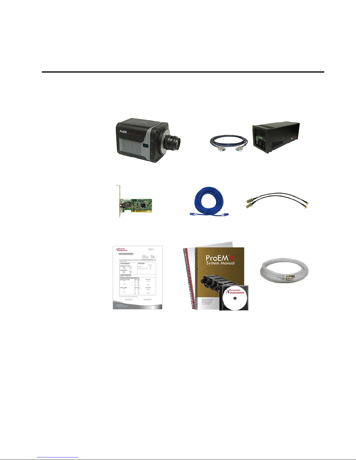
This chapter provides in introduction to, and overview information about, Princeton
Instrument’s ProEM-HS camera system. Figure 2-1 shows those items that are typically
included as part of a standard ProEM-HS Camera System.
Figure 2-1: Typical ProEM-HS System Components
Standard items include:
• ProEM-HS Camera and Users Manual;
• Power Supply and Cable;
• Ethernet Card;
• Gigabit Ethernet cable;
• MCX to BNC Cable(s);
• Certificate of Performance;
• Data Acquisition Software;
• Coolant Hoses.
17
Page 18
18 ProEM-HS User Manual Issue 2
Low Noise
For standard, high dynamic
range applications
Multiplication Gain
For high speed, low
light level applicationsapplications
Readout
Amplifier
Output or Sensor Node
Output or Sensor Node
Extended Multiplication Register
d Serial Register
Frame-transfer Area
Sensor Area
High Voltage Clock
Readout
Amplifier
Normal Voltage Clock
Standar
4411-0149_0002
2.1 ProEM-HS Camera
The ProEM-HS camera features on-chip multiplication gain, a technology that enables the
multiplication of photon generated charge right on the CCD. This approach offers an
effective alternative to traditional ICCD cameras for many non-gated, low-light
applications.
The back-illuminated EMCCDs with dual amplifiers ensure optimal performance not only
for applications that demand the highest available sensitivity but also for those requiring a
combination of high quantum efficiency and wide dynamic range.
Deep thermoelectric cooling and state-of-the-art electronics are employed to help suppress
system noise. Imaging cameras can be operated at up to 30 MHz for high-speed imaging
(20 MHz for ProEM-HS:512BX3 systems,) or slower for high-precision photometry.
Spectroscopy cameras can be operated at up to 8 MHz. Increased frame rates are achievable
via subregion readout.
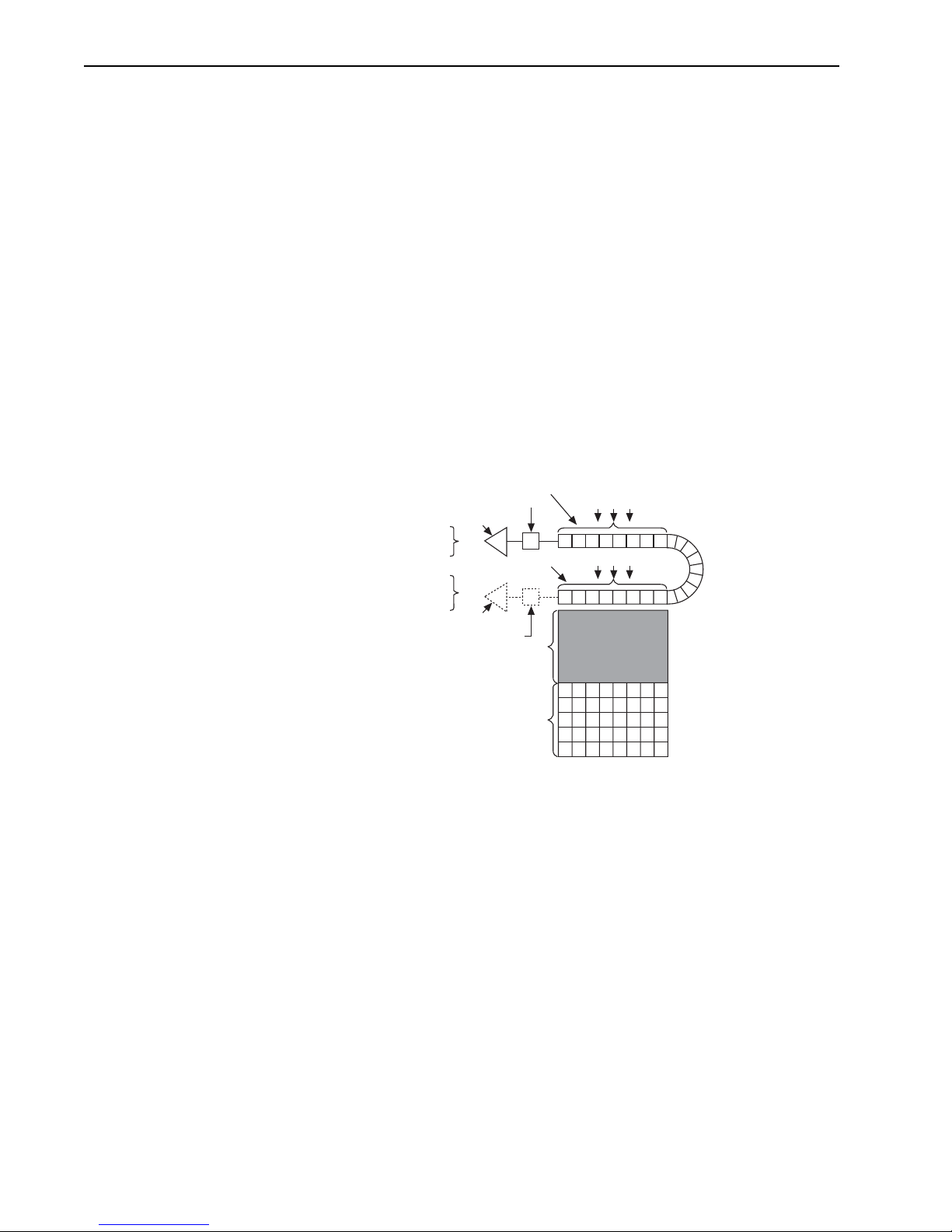
2.1.1 EMCCD Technology and On-Chip Multiplication Gain
The primary difference between an Electron-Multiplying CCD (EMCCD) and a traditional
CCD is an extended serial register in the EMCCD device. See Figure 2-2.
Figure 2-2: ProEM-HS Frame Transfer versus Kinetics EMCCD Array Structures
Electrons are accelerated from pixel to pixel in the extended portion of the serial register
(also referred to as a multiplication register) by applying higher-than-typical CCD clock
voltages. This causes secondary electrons to be generated in the silicon by impact
ionization. The degree of multiplication gain is controlled by increasing or decreasing the
clock voltages for this register (gain is exponentially proportional to the voltage.) Although
the probability of generating secondary electrons is fairly low (typically 0.01 per stage,)
over the large number of stages of a typical multiplication register, the total gain can be
quite high.
Page 19

Chapter 2 ProEM-HS Camera System 19
NOTE:
CAUTION!
!
This technology combines the ease of use and robustness of a traditional CCD with the gain
capabilities of an intensified CCD in a single device. The combination of this technology
with frame-transfer readout makes the ProEM-HS cameras excellent choices for
experiments where fast framing and low light sensitivity are required.
As the on-chip multiplication introduces additional noise, it is
recommended that the multiplication be used only as required.
For more information, refer to the “On-Chip Multiplication
Gain” technical note available for viewing or download here:
www.princetoninstruments.com/Uploads/Princeton/
Documents/Whitepapers/onchipgain.pdf
2.1.2 Integrated Controller
The ProEM-HS camera is regulated by an internal controller which converts input signals
from the host computer to appropriate control signals for the camera. These signals include
extensive capabilities for synchronizing the operation of the ProEM-HS system with the rest
of an experiment. The controlling electronics also collect analog signals from the CCD,
digitize them, and sends them to the host computer.
The ProEM-HS allows read rates, binning parameters, and regions of interest to be
configured and controlled by the data acquisition software. For instance, if an experiment
requires rapid image acquisition, then the CCD’s on-chip binning can be set to increase
frame rates.
2.1.3 Power
All voltages required by ProEM-HS cameras are generated and delivered by an external
power supply included with each ProEM-HS camera.
Refer to Section A.4, Input Power Specifications, on page 158 for complete specification
information.
2.1.4 CCD Arrays
The ProEM-HS camera systems are the most advanced EMCCD cameras available on the
market today, utilizing the latest low-noise read out electronics and back-illuminated
EMCCDs to deliver single photon sensitivity. In addition, these cameras feature, for the first
time, the latest Gigabit Ethernet (GigE) interface that allows remote operation over a single
cable without the need for custom frame grabbers. The all metal, hermetic vacuum seals
used in the ProEM-HS cameras are warrantied for life, the only such guarantee in the
industry. The EMCCD with eXcelon3 technology offers the lowest etaloning in the NIR,
and enhanced QE in blue and red.
For complete specifications and information about CCDs used in ProEM-HS cameras, refer
to Table A - 1, CCD Array Specifications, on page 157.
Use of a power supply other than that provided with the
ProEM-HS camera will void the camera warranty. For specific
power supply requirements, contact Princeton Instruments.
Refer to Contact Information on page 184 for complete
information.
Page 20

20 ProEM-HS User Manual Issue 2
NOTE:
2.1.5 Cooling
Dark current is reduced in ProEM-HS camera systems through thermoelectric cooling of the
CCD arrays. Cooling by this method uses a Peltier cooler in combination with air
circulation provided by an internal fan and/or circulating coolant. To prevent condensation
and contamination from occurring, cameras cooled this way are evacuated. Due to CCD
size/packaging differences, the lowest achievable temperature can vary from one
ProEM-HS model to the next. Refer to Tab l e A - 2 , Default Operating Temperature, on
page 158 for specific cooling information.
A feature of air-cooled ProEM-HS cameras is software control of the fan On/Off status.
When vibration may affect results, the user can turn off the fan operation while making sure
that the coolant is circulating through the camera to maintain the CCD cooling temperature.
When operating a ProEM-HS camera at or above 20 MHz and
binning is used, it is recommended that the camera be
configured for a slightly lower temperature set point than
usual. Heat generated by the CCD may result in the camera's
temperature drifting/warming and not remaining in a locked
temperature state. The recommended temperature is -50°C.
2.1.5.1 Internal Fan
The ProEM-HS camera is equipped with an internal cooling fan that:
• Removes heat from the Peltier device that cools the CCD array, and
• Cools the electronics.
An internal Peltier device directly cools the cold finger on which the CCD is mounted. Air
drawn into the camera through the back of the camera removes the heat produced by the
Peltier device and then vents out through the slots on the side panels. By default, the fan is
always in operation and air-cooling of both the Peltier and the internal electronics takes
place continuously. In most cases, the low-vibration fan action does not adversely affect the
image. However, if vibration would reduce image quality and the ProEM-HS is also being
cooled via a coolant circulator, the fan can be turned off.
For the fan to function properly, uninhibited air circulation must be maintained between the
sides of the camera and the laboratory atmosphere.
2.1.5.2 External Cooling Circulator
In addition to using an internal fan to remove heat, ProEM-HS cameras can be cooled by
circulating coolant to provide a low vibration system for data acquisition. Although the
coolant circulator can be any commercially available circulator provided it is capable of
continuously pumping a 50:50 mixture of room temperature (23ºC) water and ethylene
glycol at 1 liter per minute, Princeton Instruments’ CoolCUBE
to Section 2.7.1, CoolCUBE
desired, contact Princeton Instruments for additional recommendations.
is an ideal solution. Refer
II
Coolant Circulator, on page 26 for additional information. If
II
2.1.5.3 Coolant Ports
Two inlet/outlet ports on the side of the ProEM-HS camera allow it to be connected to a
Princeton Instruments CoolCUBE
Circulator.
II
Page 21
Chapter 2 ProEM-HS Camera System 21
4411-0149_0003
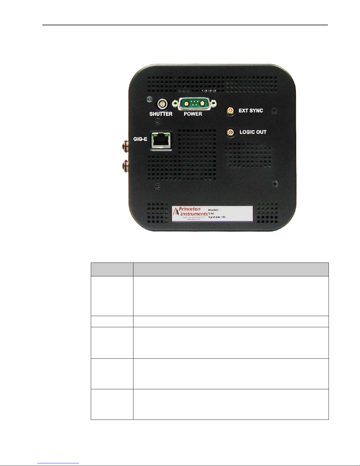
2.1.6 Rear-Panel Connectors
Figure 2-3 illustrates the rear-panel connectors on a ProEM-HS camera.
Figure 2-3: ProEM-HS Rear-Panel Connectors
Refer to Table 2-1 for information about each rear-panel connector.
Table 2-1: ProEM-HS Rear-Panel Connectors
Label Description
Shutter
Power Power input from external power supply provided with the ProEM-HS system
EXT SYNC 0-+3.3 V
LOGIC OUT 0 to +3.3 V programmable TTL-compatible logic level output. The output of this
Gig-E Gigabit Ethernet connector. Used with the Cat 5e/6 Gigabit Ethernet cable (supplied)
LEMO® connector for driving an external shutter equipped with a 25 mm connector. Stop
data acquisition and turn off the power supply before connecting to or disconnecting from
this connector.
NOTE: When an internal shutter is installed, this connector cannot drive an external
shutter.
TTL-compatible logic level input with a 10 k pull-up resistor. Allows data
DC
acquisition and readout to be synchronized with external events. Positive or negative
(default) edge triggering can be selected. For information about Synchronization and
Timing Modes, refer to Chapter 8, Experiment Synchronization, on page 101.
connector can be programmed and can also be inverted via the application software. For
complete information about each output signal, refer to Section 8.4, LOGIC OUT
Control, on page 107.
interconnecting the camera and the GigE interface card in the host computer. A high
quality cable must be used to preserve data integrity during transmission. The cable can
extend the distance between camera and the host computer by more than 50 m.
Page 22
22 ProEM-HS User Manual Issue 2
2.2 Cables
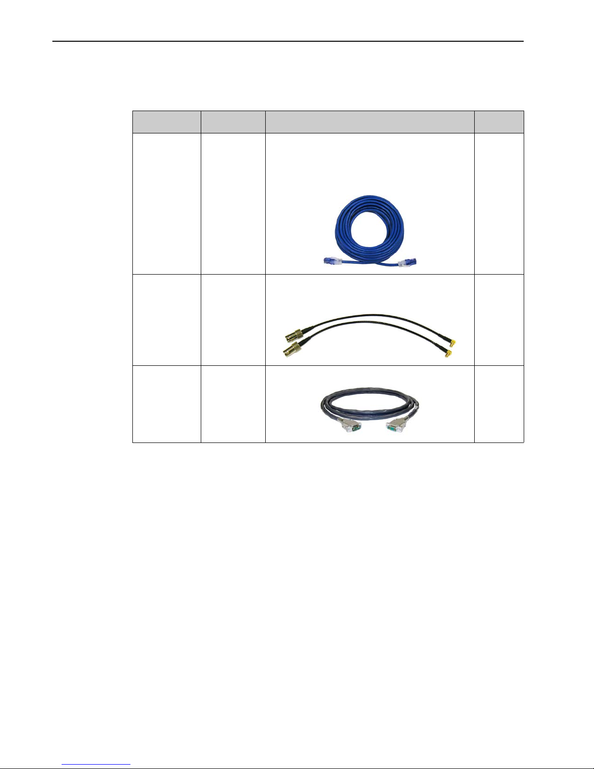
Table 2-2 describes the cables included with a standard ProEM-HS Camera System.
Table 2-2: Standard ProEM-HS Camera System Cables
Cable Part Number Description/Purpose Length
Ethernet 6050-0621 Cat 5e/6 Ethernet cable. Connects the ProEM-HS
camera to the host computer.
The detector and the computer may be more than
50 meters apart. Contact the factory to order longer
cables.
MCX to BNC 6050-0540 Two MCX to BNC adapter cables are included. These
connect to the EXT SYNC and the LOGIC OUT
connectors on the rear of the ProEM-HS.
Power 6050-0673 Connects the ProEM-HS detector to the power supply. 3 m
5 m
[16.4 ft]
Va ri e s
[9.8 ft]
Page 23

Chapter 2 ProEM-HS Camera System 23
2.3 Certificate of Performance
Each ProEM-HS camera is shipped with a Certificate of Performance which states that the
camera system has been assembled and tested according to approved Princeton Instruments
procedures. It documents the camera’s performance data as measured during the testing of
the ProEM-HS and lists the following camera- and customer-specific information:
• Sales Order Number;
• Purchase Order Number;
• Camera Serial Numbers
This information is useful when contacting Princeton Instruments Customer Support.
2.4 ProEM-HS System User Manual
The ProEM-HS System User Manual describes how to install, configure, and use a
ProEM-HS camera and its components.
2.5 Application Software
Princeton Instruments offers a number of data acquisition software packages for use with
ProEM-HS camera systems, including:
• LightField
The ProEM-HS camera can be operated using LightField,
Princeton Instruments’ 64-bit Windows
package. LightField combines complete control over Princeton
Instruments’ cameras and spectrographs with easy-to-use tools
for experimental setup, data acquisition and post-processing.
LightField makes data integrity priority #1 via automatic saving
to disk, time stamping and retention of both raw and corrected
data with full experimental details saved in each file. LightField
works seamlessly in multi-user facilities, remembering each
user’s hardware and software configurations and tailoring options
and features accordingly. The optional, patent-pending
IntelliCal™ package is the highest-performance wavelength
calibration software available, providing up to 10X greater
accuracy across the entire focal plane than competing routines.
A PDF version of the LightField User Manual is provided on the installation CD.
The manual describes how to install and use the LightField application program.
Additional information is available in the program's online help.
• PICam™
The standard 64-bit software interface for cooled CCD cameras from Princeton
Instruments. PICam is an ANSI C library of camera control and data acquisition
functions. Currently, the interface supports Windows Vista and Windows 7.
• Scientific Imaging ToolKit™ (SITK™)
A collection of LabVIEW
third party software can be purchased from Princeton Instruments.
®
®
7 compatible software
®
VIs for scientific detectors and spectrographs. This
Page 24

24 ProEM-HS User Manual Issue 2
NOTE:
• WinX
The ProEM-HS camera can be operated by using either WinView/
32 or WinSpec/32, Princeton Instrument's 32-bit Windows®
software packages designed specifically for high-end imaging and
spectroscopy, respectively. The Princeton Instruments' software
provides comprehensive image/spectral capture and display
functions. The package also facilitates snap-ins to permit
advanced operation. Using the optional built-in macro record function, you can also
create and edit your own macros to automate a variety of operations. WinView and
WinSpec take full advantage of the versatility of the ProEM-HS camera and even
enhance it by making integration of the detection system into larger experiments or
instruments an easy, straightforward endeavor.
The WinX User Manual describes how to install and use the application program. A
PDF version of the manual is provided on the installation CD. Additional
information is available in the program's online help.
• PVCAM
®
A standard software interface for cooled PDA, FPA, and CCD detectors from Roper
Scientific. It is a library of functions that can be used to control and acquire data
from the detector when a custom application is being written. For example, in the
case of Windows, PVCAM is a Dynamic Link Library (DLL.) Also, it should be
understood that PVCAM is solely for detector control and image acquisition, not
for image processing. PVCAM places acquired images into a buffer, where they can
then be manipulated using either custom written code or by extensions to other
commercially available image processing packages.
ProEM-HS cameras may also be operated by several other
third-party software packages. Please check with the providers
of the packages for compatibility and support information.
Page 25

Chapter 2 ProEM-HS Camera System 25
NOTE:
2.6 Minimum Host Computer Specifications
Computers and operating systems experience frequent updates.
Therefore, the following sections are intended to provide
minimum system requirements for operating a ProEM-HS
camera.
A faster computer with 5 GB or larger memory (RAM)
greatly enhance the software performance during live mode
operations.
Contact the factory to determine specific requirements.
2.6.1 LightField Requirements
• Windows
• 2 GHz dual core processor
• 4 GB RAM (or greater)
• CD-ROM drive
• Super VGA monitor and graphics card supporting at least 65535 colors with at least
128 MB of memory. Memory requirement is dependent on desired display
resolution.
• Hard disk with a minimum of 1 GB available for installation. Additional space is
required for data storage: the amount of space required depends on the number and
size of images/spectra collected. Disk level compression programs are not
recommended. Drive speed of 10,000 RPM recommended.
• Mouse or other pointing device.
®
7/8 (64-bit)
will
2.6.2 WinX Requirements
• Windows
• 2 GHz Pentium
• 1 GB RAM (or greater)
• CD-ROM drive
• At least one unused PCI card slot (PCI 2.3 compliant 32-bit 33/66 MHz bus)
• Super VGA monitor and graphics card supporting at least 65535 colors with at least
128 MB of memory. Memory requirement is dependent on desired display
resolution.
• Hard disk with a minimum of 1 GB available. A complete installation of the
program files takes about 50 MB and the remainder is required for data storage,
depending on the number and size of images/spectra collected. Disk level
compression programs are not recommended. Drive speed of 10,000 RPM
recommended.
• Mouse or other pointing device.
®
XP (32-bit with SP3 or later)
®
4 (or greater)
Page 26
26 ProEM-HS User Manual Issue 2
CAUTION!
!
WARNING!
2.7 Accessories
Princeton Instruments offers a number of optional accessories that are compatible with
ProEM-HS. This section provides information about each of them. For complete ordering
information, contact Princeton Instruments.
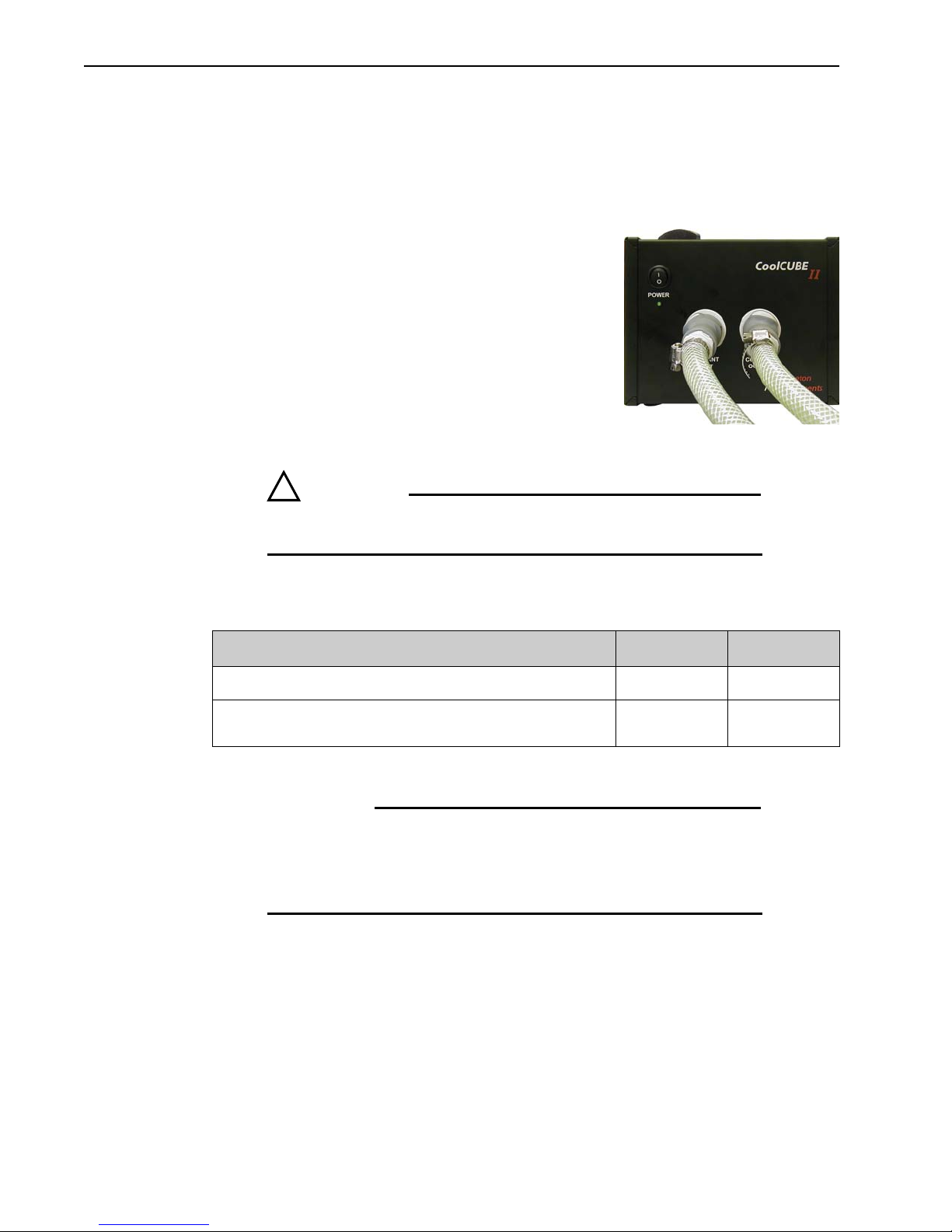
2.7.1 CoolCUBEII Coolant Circulator
Princeton Instruments’ CoolCUBEII circulator can be
used to cool the ProEM-HS by continuously pumping
coolant that is a 50:50 mixture of:
• Room temperature water, and
• Ethylene glycol.
This mixture is pumped through the ProEM-HS chamber
at a rate of 1 liter per minute.
Two 10 mm (3/8”) ID, 3 meter (10 ft) long coolant hoses
are supplied with each system. These hoses mate with the
ProEM-HS fittings (part number 2550-0630.) Additional
hoses can be ordered separately from Princeton Instruments.
To prevent voiding the ProEM-HS warranty, only use the
circulator and hoses that have been provided with the system.
Table 2-3 provides information about the nozzles and barbs that comprise the coolant ports.
Table 2-3: Cooling Port Coupling Information
Description Manufacturer Part Number
QDC (Low Profile) Male Shutoff Nozzles
VL2 Quick Disconnect Low-Spill Coupling, Female Panel Barb for
ID 10mm (3/8in)
a. www.koolance.com
Koolance
Koolance VL2-F10B-P
a
VL2-MG
When using a third-party chiller, it is imperative that the
coolant temperature never falls below the Dew Point in order
to avoid permanent damage to the ProEM-HS camera.
Contact Princeton Instruments for further information.
Page 27
Chapter 2 ProEM-HS Camera System 27
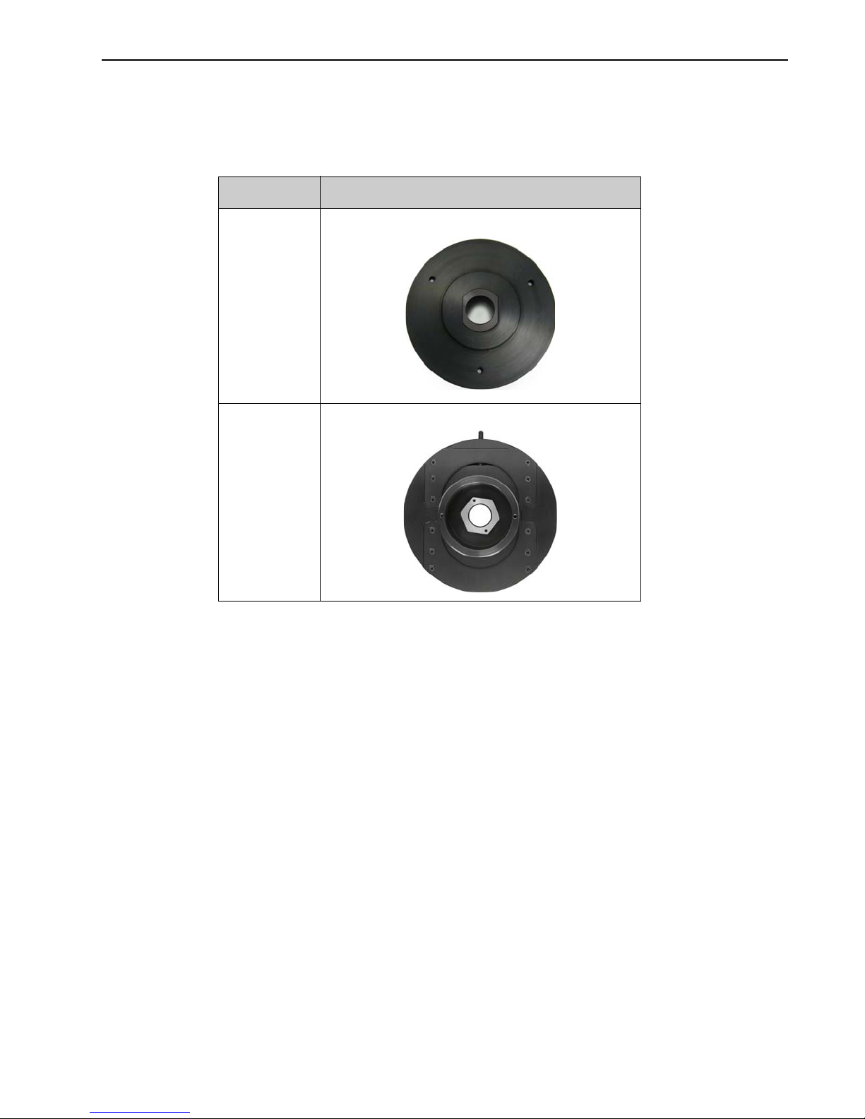
2.7.2 Spectroscopy Mounts
Refer to for information about available spectroscopy mounts for the ProEM-HS camera
system.
Table 2-4: Available Spectroscopy Mounts for the ProEM-HS
Part Number Description
7050-0083 C- to Spectroscopy-Mount Adapter
7050-0107
Adjustable C- to Spectroscopy-Mount Adapter
Page 28

28 ProEM-HS User Manual Issue 2
WARNING!
2.8 ProEM-HS Camera and System Maintenance
Turn off all power to the equipment and secure all covers
before cleaning the units. Otherwise, damage to the equipment
or injury to you could occur.
2.8.1 Camera
Although there is no periodic maintenance that is required for a ProEM-HS camera, users
are advised to wipe it down with a clean damp cloth from time to time. This operation
should only be done on the external surfaces and with all covers secured. In dampening the
cloth, use clean water only. No soap, solvents or abrasives should be used. Not only are they
not required, but they could damage the finish of the surfaces on which they are used.
2.8.2 Optical Surfaces
The ProEM-HS camera has an integrated shutter that protects the camera window from dust
when not in use. Should a need to clean the optical window arise due to the accumulation of
atmospheric dust, we advise that the drag-wipe technique be used. Before starting the
procedure, run the camera and disable the shutter open to get access to the window. Then,
dip a clean cellulose lens tissue into clean anhydrous methanol and drag the dampened
tissue over the optical surface to be cleaned. Do not allow any other material to touch the
optical surfaces. Pay extra attention if the optical window is coated with AR (antireflection) materials as they can be susceptible to scratches. Please contact factory if you
have any questions.
2.8.3 Repairs
Because the ProEM-HS camera system contains no user-serviceable parts, repairs must be
performed by Princeton Instruments. Should your system need repair, contact Princeton
Instruments customer support for instructions. Refer to Contact Information on page 184 for
complete contact information.
Save all original packing materials and use them whenever shipping the system or system
components.
Page 29

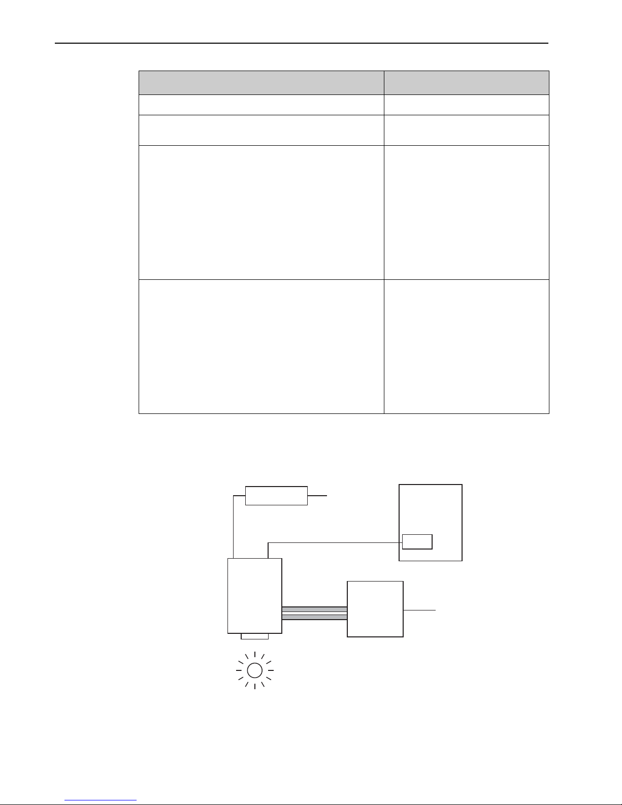
Chapter 3: System Installation
Perform the following procedure to install the system and prepare to collect data. Refer to
the indicated references for detailed information:
Table 3-1: System Installation (Sheet 1 of 2)
Action Refer to…
1. If the system components have not already been
unpacked, unpack them and inspect their carton(s)
and the system components for in-transit damage.
2. Verify that all system components have been
received.
3. If the components show no signs of damage, verify
that the appropriate power cord has been supplied
with the power supply.
4. If the Ethernet adapter card provided with the system
is not already installed in the host computer, install
it.
5. If the application software is not already installed in
the host computer, install it.
6. Depending on application, attach lens to the camera
or mount the camera to a spectrograph.
Section 4.1, Unpack the System, on
page 33.
Section 4.2, Verify Equipment and Parts
Inventory, on page 34.
–
Refer to the manufacturer's instructions.
Section 4.8, Application Software
Installation, on page 40, and relevant
software manuals.
Section 4.3, Attaching a Lens to a CMount Adapter, on page 34;
Section 4.4, Mounting the Adjustable Cto Spectroscopy-Mount Adapter, on
page 36;
Appendix C, Mounting a ProEM-HS to a
Spectrograph, on page 167.
7. With the power supply disconnected from the
camera, connect the Ethernet cable to the GigE
connector on the rear of the camera and to the
Ethernet port on the installed Ethernet card.
8. Air-Cooled System: Plug the power supply into the
rear of the camera and plug the power supply into the
power source.
Liquid Cooling (optional): Make the hose
connections to the camera and plug the circulator
into the power source. Add coolant if necessary.
Turn on the circulator.
9. Turn the camera on.
10. Turn on the computer and launch the data acquisition
software.
–
–
Section 4.7, Connect a CoolCUBEII
Circulator, on page 39.
–
Relevant software manual
29
Page 30
30 ProEM-HS User Manual Issue 2
4411-0149_0004
POWER SUPPLY
ETHERNET CABLE
POWER CABLE
GIGE
G
IG-E CARD
COOLANT
COOLANT CIRCULATOR
COOLANT
COOLANT
100-240 V
S
AMPLE
CAMERA
HOST COMPUTER
100-240 V
H
OSES
Table 3-1: System Installation (Sheet 2 of 2)
Action Refer to…
11. Enter the hardware setup information.
12. Set the target array temperature.
13. When the system reaches temperature lock, wait an
additional 20 minutes before beginning data
acquisition in focus mode.
14. Adjust the focus for the best image or spectral lines.
• LightField: Use the Align Spectrometer
function.
• WinX: Use the Focus Helper function for
spectroscopy applications.
Relevant software manual
Section 7.4, CCD Temperature, on
page 84.
LightField:
• Imaging: Section 5.1.2, Data
Acquisition, on page 49;
• Spectroscopy: Section 5.2.3, Data
Acquisition, on page 59;
WinX:
• Imaging: Section 6.2.3, Focus the
System, on page 67;
• Spectroscopy: Section 6.3.6,
Focus the System, on page 78;
•
Imaging: Section 5.1.2, Data
Acquisition, on page 49;
• Spectroscopy: Section 5.2.3, Data
Acquisition, on page 59;
• Imaging: Section 6.2.3, Focus the
System, on page 67;
• Spectroscopy: Section 6.3.6,
Focus the System, on page 78;
3.1 System Configuration Diagrams
This section provides block diagrams of typical system configurations.
Figure 3-1: Typical Imaging Experiment Layout with Air-cooled Camera
Page 31

Chapter 3 System Installation 31
4411-0149_0005
POWER SUPPLY
ETHERNET CABLE
POWER CABLE
GIGE
G
IG-E CARD
SPECTROMETER
100-240 V
S
AMPLE
CAMERA
HOST COMPUTER
4411-0149_0006
POWER
ETHERNET CABLE
POWER
GIGE
G
IG-E CARD
SPECTROGRAPH
100-240 V
S
AMPLE
CAMERA
HOST COMPUTER
OPTIONAL
SHUTTER
CONNECTION
GIGE
SUPPLY
CABLE
Figure 3-2: Typical Spectroscopy Experiment Layout with Air-cooled Camera
Figure 3-3: Typical Spectroscopy Experiment Layout with Air-cooled Camera and
IsoPlane
Page 32

32 ProEM-HS User Manual Issue 2
Figure 3-4: Typical Imaging Experiment Layout with Air/Liquid-cooled Camera
Figure 3-5: Typical Spectroscopy Experiment Layout with Air/Liquid-cooled Camera
Page 33

Chapter 4: System Setup
NOTE:
To minimize risk to users or to system equipment, turn the
system OFF before any cables are connected or disconnected.
A ProEM-HS camera system includes the following items:
• ProEM-HS Camera;
• Power supply;
• GigE adapter card;
• Cables:
— Ethernet;
— Power;
— MCX-to-BNC.
All required items should be included with the shipment. The ProEM-HS system has been
specially configured and calibrated to match the camera options specified at the time of
purchase. The CCD window and coatings that were ordered have been installed in the
camera head.
Keep all the original packing materials so that the ProEM-HS system can be easily and
safely to another location or returned for service if necessary. If assistance is required at any
time, call Princeton Instruments Customer Support. For contact information, refer to
Contact Information on page 184.
Hardware installation consists of:
• Installing a dedicated GigE interface card.
• Attaching a lens to a C-mount on the camera or to a C- to F-mount adapter.
• Mounting the camera to a spectrograph (for spectroscopy applications).
Software installation depends on the specific data acquisition software being used. Refer to
the manual supplied with the software for information about installation and configuration.
4.1 Unpack the System
When unpacking the system, examine the system components for possible signs of shipping
damage. If there are any, notify Princeton Instruments and file a claim with the carrier. Be
sure to save the shipping carton for inspection by the carrier. If damage is not apparent but
system specifications cannot be achieved, internal damage may have occurred in shipment.
Please save the original packing materials so you can safely ship the camera system to
another location or return it to Princeton Instruments for repairs if necessary.
33
Page 34

34 ProEM-HS User Manual Issue 2
CAUTION!
!
4.2 Verify Equipment and Parts Inventory
Verify that all equipment and parts required to set up the ProEM-HS system have been
delivered. A typical system consists of:
• Camera
• Power Supply
• Host Computer: Can be purchased from Princeton Instruments or provided by user.
For enhanced performance, a fast hard drive (10,000 rpm) and 2 GB RAM is
recommended.
• Operating System:
— WinView/32 or WinSpec/32: Windows XP, 32-bit, SP3 or later
— LightField: Windows 7 (64-bit)
• Computer Interface Components:
— Ethernet Cable: 15 ft (5 meter) cable (6050-0621) is standard.
— GigE Interface Card (provided with the ProEM-HS system)
• External Sync and Logic Out Cables: MCX-to-BNC adapter cables.
• Hoses: Two coolant hoses with ProEM-HS-compatible quick-disconnects.
• ProEM-HS System User Manual
• Application Software:
— WinView/32 or WinSpec32 (Ver. 2.6.10 or later) CD-ROM (optional)
— LightField CD-ROM (optional)
• Software User Manual (provided with application software)
4.3 Attaching a Lens to a C-Mount Adapter
Overexposure protection: Cameras exposed to room light or
other continuous light sources will quickly become saturated.
Set the lens to the smallest aperture (i.e., largest f-number,) and
cover the lens with a lens cap to prevent overexposure.
ProEM-HS cameras for imaging applications incorporate an integrated C-mount adapter.
Other mounts may be available. Consult the factory for specific information relating to
specific requirements. Refer to Contact Information on page 184 for complete contact
information.
Page 35

Chapter 4 System Setup 35
NOTES:
4.3.1 Mounting the Lens
C-mount lenses screw into the front of the ProEM-HS camera. Tighten the lens by hand only.
1. If the CCD is cooled to low temperatures (below -50°C),
exposure to ambient light will over-saturate it. This may
increase dark charge significantly. If the camera remains
saturated after all light sources are removed, you may have
to bring the camera back to room temperature to restore
dark charge to its original level.
2. Saturation is not harmful to a non-intensified camera, but it
should be avoided.
4.3.2 Adjusting the C-Mount Adapter
Figure 4-1: Adjustable C-Mount Adapter
Page 36

36 ProEM-HS User Manual Issue 2
NOTE:
CAUTION!
!
The ProEM-HS features an adjustable C-mount adapter that allows you to change the focal
depth. Use the hex key supplied with your system (or a 0.050" hex key) to loosen the
setscrew securing the adapter. Using a spanner wrench or equivalent (distance between
holes is 3.85” [97.8 mm]), rotate the ring to the desired height. Tighten the screw to lock the
adapter in place.
To lock the setscrew, the face of the adapter should be no
further than 0.1" (2.5 mm) out from the front surface of the
camera nose.
The C-mount lens thread-depth should be 0.21" (5.33 mm) or
less. Otherwise, depending on the adapter in-out location, the
lens could bottom out and damage the shutter. If you are not
certain of the thread depth, remove the adapter from the camera
nose, thread the lens into the adapter until the lens threads are
flush with the back surface of the adapter. Note the depth at the
front surface, remove the lens, and then re-insert the adapter
into the camera nose.
4.4 Mounting the Adjustable C- to Spectroscopy-Mount Adapter
The adjustable C- to spectrograph-mount adapter allows you to move the camera vertically
at the exit plane of an Acton Series spectrograph in order to align the kinetics rows at the
middle of the focal plane for the best spectral quality. The adapter is mounted to the front of
a ProEM-HS camera and is secured to the camera by a threaded insert screwed into the
camera’s C-mount opening. See Figure 4-2 when mounting the adapter to the camera.
• Tools Required:
— 0.050” Hex key
— 3/32” hex key
— Flat screwdriver
— Spanner wrench (1.17”/29.7 mm between 0.094”/2.38 mm diameter holes)
• Equipment:
— Acton Series Spectrograph with light source at entrance port
— Kinetics Adapter
• SP-2150 and SP-2750 Spectrographs: Use the Model 7050-0107 adapter
• SP-2350 and SP-2550 Spectrographs: Use the Model 7050-0104 adapter
— Camera with C-mount nose
Page 37

Chapter 4 System Setup 37
REFERENCES:
4.4.1 Procedure
Perform the following procedure to mount an adjustable C- to Spectroscopy-Mount adapter:
1. If a light baffle is mounted to the front of the adapter, remove the two 2-56 screws
securing it and set the baffle aside.
2. Orient the adapter with the setscrew at the top as shown in Figure 4-2 and, using a
spanner wrench or equivalent (distance between holes is 1.17” [29.7 mm]), tighten the
threaded insert into the C-mount opening on the camera.
Figure 4-2: Adjustable C- to Spectroscopy-Mount Adapter
3.
When using a light baffle, mount the light baffle to the front of the adapter.
4. Gently rotate the camera and sliding tube assembly as you insert it into the
spectrograph’s exit port.
5. With the spectrograph, camera, and light source powered on and connected to the
computer (as required), start the application software.
Refer to the following sections for information about focusing
and rotationally aligning the ProEM-HS camera to the
spectrograph optics:
• LightField: Section 5.2.2, Rotational Alignment and
Focus, on page 54;
• WinSpec/32: Section 6.3.5, Rotational Alignment, on
page 75, and Section 6.3.6, Focus the System, on
page 78.
6. When you have finished with focusing and rotational alignment, secure the sliding tube
in place with the spectrograph setscrews.
Page 38

38 ProEM-HS User Manual Issue 2
NOTE:
7. If they have already been installed, loosen the adapter’s two recessed locking setscrews
(use a 0.050 hex key). If they have not been installed, insert the setscrews into the holes
at the sides of the adapter and screw them in a couple of turns.
8. When the camera opening is centered within the sliding tube, you can adjust the camera
up or down 0.4” (4.06 mm) by tightening or loosening the vertical adjustment setscrew
(use a 3/32” hex key.)
9. After you have completed the adjustment, tighten the recessed locking setscrews in the
adapter flange to lock the position.
4.5 Positioning ProEM-HS Masks
This option is not available for ProEM-HS: 1024B cameras.
The ProEM-HS camera has a kinetics nose that provides built-in precision masking
capability and manual shutter adjustment. After using the pull-push sliders to coarsely set
the position of the top and bottom masks, you can then use the micro-adjust screws while
viewing images being acquired by the application software to fine tune the masking. The
pull-push knob for the manual shutter allows you to block all light from the camera while
you are acquiring a background.
Figure 4-3: Front View of ProEM-HS Camera
Page 39

Chapter 4 System Setup 39
NOTES:
4.6 Opening/Closing ProEM-HS Manual Shutter
ProEM-HS cameras include a built-in manual shutter that allows you to block all light from
the camera while you are acquiring a background. To operate the shutter, pull the knob out
to close the shutter and push it in to open it.
Figure 4-4: Front View of ProEM-HS Camera
4.7 Connect a CoolCUBEII Circulator
For liquid-cooled cameras, the CoolCUBEII circulator provides a
vibration-free method of heat removal.
1. Make sure the camera and the circulator power switches are
turned off.
2. Make sure the circulator is 6 inches (150 mm) or more below
the camera. The vertical distance should not exceed 10 feet
(3 m). Typically, the camera is at table height and the
circulator is on the floor.
3. Make the coolant connections between the circulator and the camera. It does not matter
which hose from the circulator is plugged into a coolant port on the camera.
4. It is recommended that hoses be secured to the camera hose barbs with the clamp
supplied.
1. Make sure that there are no kinks in the hoses that impede
the coolant flow. Lack of sufficient flow can seriously
harm the camera and any resulting damage is not covered
under warranty.
2. Damage caused by water leaking into the ProEM-HS voids
the warranty.
5. Unscrew the reservoir cap (on top of the CoolCUBE
sure that the coolant reservoir contains coolant. If additional coolant
is required, fill with a 50:50 mixture of water and ethylene glycol.
6. Screw the reservoir cap back in.
7. Plug the circulator into a 100-240 V
) and make
II
, 50-60 Hz power source.
AC
Page 40

40 ProEM-HS User Manual Issue 2
NOTE:
NOTE:
8. Turn the circulator on. Make sure there are no leaks or air bubbles in the hoses.
Small air bubbles (about the size of bubbles in soda) are
common in the CoolCUBE
especially at start up and do not
II
prevent proper operation.
a. If there are no problems, continue to Step 9.
b. If there are leaks or air bubbles, turn the circulator off and correct the problem(s) by
securing the hoses or adding more coolant to the reservoir. Turn the circulator back
on. Recheck and if there are no problems, continue to Step 9.
9. Turn the camera on.
10. Launch the application software.
4.8 Application Software Installation
This section provides detailed procedures for the installation of supported application
software.
4.8.1 LightField
This section provides the installation procedure for LightField application software.
Install the GigE Adapter card BEFORE installing the
LightField application software.
Before beginning to install LightField, verify that:
• The operating system on the desired host computer is either Windows Vista (64-bit)
or Windows 7 (64-bit);
• A GigE adapter card has been installed;
• The host computer is connected to the Internet. Internet connection may be required
for product activation.
Page 41

Chapter 4 System Setup 41
4411-0149_0006
Perform the following procedure to install LightField on the host computer:
1. Insert the LightField Installation CD into the CD drive on the host computer, and follow
the on-screen prompts.
Figure 4-5 illustrates a typical InstallShield Wizard dialog.
Figure 4-5: Typical LightField InstallShield Wizard Dialog
2.
After the installation has been completed, reboot the computer.
3. Connect the ProEM-HS system components to the host computer and apply power.
4. Launch LightField, activate it, and begin setting up your experiment.
Page 42

42 ProEM-HS User Manual Issue 2
NOTES:
4411-0149_0005
4.8.2 WinX Application
This section provides the installation procedure for WinX application software.
1. Install the GigE Adapter card BEFORE installing the
WinX application software.
2. The interface cable should remain disconnected from the
camera until after WinX (Ver. 2.6.10 or later) has been
successfully installed.
Perform the following procedure to install WinX on the host computer:
1. Insert the WinX software installation CD into the CD drive on the host computer. The
installation program will automatically launch.
2. When the Select Installation Type dialog is displayed, select the desired type of
installation.
• Typical installs all required drivers and the most commonly installed program
files;
• Complete installs all available application drivers and features;
• Custom is used to select specific features and drivers for installation, as well as
specifying a custom installation directory. This is only recommended for use by
advanced users.
Figure 4-6 illustrates a typical WinView/32 Setup dialog.
Figure 4-6: Typical WinX Setup Dialog
Click Next > to continue the installation. Follow on-screen prompts.
3.
4. Once the installation has been completed, connect the camera to the host computer and
turn on the camera’s power supply.
5. Reboot the host computer.
Windows will automatically detect the newly-installed GigE card.
Page 43

Chapter 4 System Setup 43
REFERENCES:
4.9 Configure Default Camera System Parameters
This section describes the initial configuration of default camera parameters.
4.9.1 LightField
Perform the following procedure to configure default LightField system parameters:
1. Verify the ProEM-HS (and spectrograph, if this is a spectroscopy system) is connected
to the host computer and that the camera (and spectrograph) power supply is turned on.
2. Launch LightField.
3. While LightField is starting up, it will detect the available device(s) and load the
appropriate icons into the Available Devices area in the Experiment workspace.
4. When an icon is dragged into the Experiment Devices area, the appropriate
expanders will be loaded into the Experiment Settings stack on the left-hand side of
the window. See Figure 4-7.
Figure 4-7: LightField Experiment Workspace
Because this is a new experiment, the default settings will automatically be entered for
5.
the experiment device(s). These settings will allow you to begin previewing (Run
button) or acquiring (Acquire button) data.
For information about basic system operation for Imaging and
Spectroscopic applications refer to Chapter 5, LightField First
Light, on page 45.
Page 44
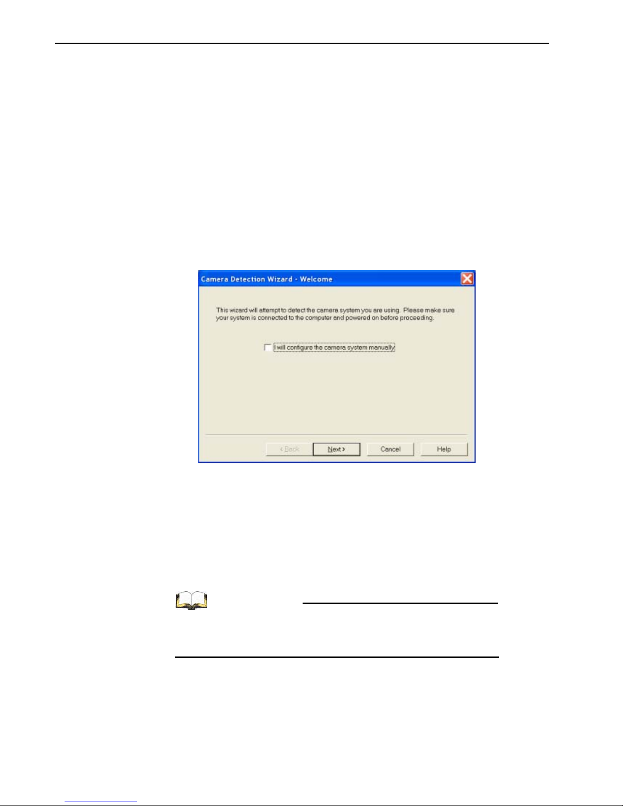
44 ProEM-HS User Manual Issue 2
REFERENCES:
4411-0149_0008
4.9.2 WinX (Versions 2.6.10 or later)
Perform the following procedure to configure default WinX system parameters:
1. Make sure the ProEM-HS (and spectrograph if configuring a spectroscopy system,) is
connected to the host computer and that its power supply is turned ON.
2. Launch the WinX application.
• The Camera Detection Wizard will automatically run if this is the first time a
Princeton Instruments WinX application (WinView/32, WinSpec/32, or WinXTest/
32) has been installed with a supported camera.
• If simply installing a new camera type, click on the Launch Camera
Detection Wizard…
3. When the Welcome dialog is displayed, the check box should remain unchecked. Click
Next.
See Figure 4-8.
Figure 4-8: Typical WinX Camera Detection Wizard Dialog
button on the Controller/CCD tab to launch the wizard.
Follow the on-screen prompts to perform the initial hardware setup.
4.
The wizard automatically enters default parameter on the Hardware Setup dialog and
provides the opportunity to acquire a test image to verify the system is working
properly. Note that this is a test image and it is not acquired using the settings needed
for true data acquisition.
When performing spectroscopy, the spectrograph must be defined by selecting Define
from the Spectrograph menu, highlighting the correct spectrograph name, and
clicking on Install Selected Spectrograph.
For information about basic system operation for Imaging and
Spectroscopic applications refer to Chapter 6, WinX/32 First
Light, on page 61.
Page 45

Chapter 5: LightField First Light
Incoming Photons
Camera
EMCCD
Preamp Electronics
Analog to Digital
Converter
Digital Processor
GigE Interface
Computer
GigE Interface
Display Storage
4411-0149_0007
Once a ProEM-HS camera has been installed as described in preceding chapters, acquiring
data using LightField is straightforward. For most applications simply:
• Establish optimum performance using Preview mode;
• Set a target camera temperature;
• Wait until the system’s temperature has stabilized;
• Acquire live data in Acquire mode.
Additional considerations regarding experiment setup and equipment configuration are
addressed in the LightField Users Manual. Refer to Table 1 -1 for document numbers
information.
During data acquisition, the CCD array is exposed to a source and charge accumulates in the
pixels. After the defined exposure time, the accumulated signal is read out of the array,
digitized, and transferred to the host computer. Upon data transfer, the data are displayed
and/or stored using LightField. This sequence is illustrated by the block diagram shown in
Figure 5-1.
Figure 5-1: Light Path Block Diagram for ProEM-HS Systems
45
Page 46

46 ProEM-HS User Manual Issue 2
REFERENCES:
NOTE:
REFERENCES:
Whether or not the data are displayed and/or stored depends on the data collection operation
that has been selected in the application software:
• Preview
This mode is typically used when setting up the system during the First Light
procedure.
For application-specific First Light procedures, refer to:
• Section 5.1, Imaging Applications, on page 47;
• Section 5.2, Spectroscopy, on page 51.
In Preview mode, the number of frames is ignored. A single frame is acquired and
displayed, another frame is acquired and overwrites the currently displayed data,
and so on until
Stop is selected.
The last frame acquired before Stop is selected cannot be
stored.
Preview mode is particularly convenient for familiarization and setting up. For ease
in focusing, the screen refresh rate should be as rapid as possible, achieved by
operating with axes and cross-sections off, and with Zoom 1:1 selected.
• Acquire
Acquire
mode is typically used for the collection and storage of data. In Acquire
mode, every frame of data collected can be automatically stored, so the completed
dataset may include multiple frames with one or more set of accumulations. This
mode is typically selected during actual data collection.
One limitation of Acquire mode operation is that if data acquisition continues at too
fast a rate for it to be stored, data overflow may occur.
For information about synchronizing data acquisition with
external devices, refer to Chapter 8, Experiment
Synchronization, on page 101.
Page 47

Chapter 5 LightField First Light 47
4411-0149_0008
5.1 Imaging Applications
This section provides step-by-step instructions for acquiring an image in LightField for the
first time. The intent of this procedure is to gain familiarity with the operation of the system
and to show that it is functioning properly. Once basic familiarity has been established,
additional, more complex configurations can be performed.
This procedure assumes:
• The system has been set up in accordance with the instructions in the previous
chapters.
• Familiarity with LightField.
If this is not the case, review the software manual or have it available while
performing this procedure.
• The camera has a frame transfer array and a software-controlled internal shutter.
• The system is being operated in imaging mode.
• The target is a sharp image, text, or a drawing that can be used to verify that the
camera is seeing and can be used to maximize focus.
5.1.1 System Set Up and Configuration
Perform the following procedure to set up and configure the system to acquire an image:
1. Mount a test target in front of the camera.
2. Power ON the camera.
3. Turn on the host computer power.
4. Launch LightField.
5. Once LightField has started, a ProEM-HS camera icon will be shown in the Available
Devices
area. See Figure 5-2.
Figure 5-2: Available Devices Area
Page 48

48 ProEM-HS User Manual Issue 2
4411-0149_0009
6. Drag the icon into the Experiment Devices area.
The
Experiment Settings stack on the left includes several expanders. Since this is a
new experiment, the default configuration settings for the camera are used. See
Figure 5-3.
Figure 5-3: Experiment Devices Area
The Status bar across the bottom of the window includes icons for temperature status
and orientation.
• Temperature Status reports the current system temperature and whether the set
temperature has been reached. Clicking on the icon, opens the
Sensor expander in
which the desired temperature can be configured.
• Orientation is displayed because the default readout port is Electron Multiplied.
Clicking on the icon opens a panel that describes how the image orientation has
been corrected.
Page 49

Chapter 5 LightField First Light 49
4411-0149_0010
5.1.2 Data Acquisition
Perform the following procedure to acquire live data:
1. Click on the View tab located above Experiment Devices: to change focus to the View
area. See Figure 5-4
Figure 5-4: View Area
2.
Click Run to initiate Preview mode.
In this mode, images are continuously acquired and displayed. See Figure 5-5.
Page 50

50 ProEM-HS User Manual Issue 2
NOTE:
4411-0149_0011
Figure 5-5: View Area Displaying an Image
3.
Adjust the lens aperture, intensity scaling, and focus for the best image as viewed on the
computer monitor.
Imaging tips include:
• Begin with the lens blocked off and then set the lens at the smallest possible
aperture (i.e., the largest f-stop number.)
• Verify there is a suitable target in front of the lens. An object with text or graphics
works best.
• Inspect the brightest regions of the image to determine if the A/D converter is at
full-scale.
A 16-bit A/D is at full scale when the brightest parts of an
image reach an intensity of 65535.
Adjust the aperture so that it is slightly smaller (i.e., a higher f-stop,) than the
setting where maximum brightness occurs on any spot of the image.
• Set the focus adjustment of the lens for maximum sharpness in the viewed image.
4. After the camera has been successfully focused, either:
• Exit/stop Preview mode;
• Continue Preview mode;
• Begin Acquire mode;
• Wait for the CCD to reach the operating temperature before starting Acquire mode;
• Shut down the system.
Refer to Section 5.3, System Shutdown, on page 59, for the recommended
shutdown procedure.
Page 51

Chapter 5 LightField First Light 51
REFERENCES:
CAUTION!
!
5.2 Spectroscopy
This section provides step-by-step instructions for acquiring a spectrum in LightField for
the first time. The intent of this procedure is to gain familiarity with the operation of the
system and to show that it is functioning properly. Once basic familiarity has been
established, additional, more complex configurations can be performed.
This procedure assumes:
• The system has been set up in accordance with the instructions in the previous
chapters. This includes mounting the camera to the spectrograph.
Refer to Appendix C, Mounting a ProEM-HS to a
Spectrograph, on page 167, for mounting instructions.
• Familiarity with LightField.
If this is not the case, review the software manual or have it available while
performing this procedure.
• The camera has full frame array and a manual shutter.
• The system is being operated in spectroscopy mode.
• The spectrograph has an entrance slit shutter that is controlled by the ProEM-HS via
the
Shutter connector.
An underlying assumption of this procedure is that the camera is to be operated with a
spectrograph (e.g., an Acton Series 2300 or IsoPlane,) on which it has been properly
installed. A suitable light source, such as a mercury pen-ray lamp, should be mounted in
front of the entrance slit of the spectrograph. Any light source with line output can be used.
Standard fluorescent overhead lamps have good calibration lines as well. If there are no line
sources available, it is possible to use a broadband source such as tungsten for the
alignment. If this is the case, use a wavelength setting of 0.0 nm for alignment purposes.
Overexposure Protection
Cameras that are exposed to room light or other continuous
light sources will quickly become saturated. If the camera is
mounted to a spectrograph, close the entrance slit of the
spectrograph to reduce the incident light.
Page 52

52 ProEM-HS User Manual Issue 2
5.2.1 System Set Up and Configuration
Once the ProEM-HS has been mounted to the spectrograph of choice, perform the following
procedure to set up and configure the system to acquire a spectrum:
1. Set the spectrograph entrance slit width to minimum (10 µm if possible.)
2. Power ON the spectrograph.
3. Mount a light source such as a Princeton Instruments IntelliCal™ Hg/Ne-Ar Dual
Switchable light source in front of the entrance slit.
4. Connect the shutter cable between the entrance slit shutter and the ProEM-HS Shutter
connector.
Verify the shutter knob for the ProEM-HS’s manual shutter is pushed in (i.e., manual
shutter is open.)
• External Slit Shutter
A shutter assembly mounted externally to the spectrograph has shutter cable that
plugs into the
• Internal Slit Shutter
A shutter mounted internally has an external shutter connector in the sidewall of the
spectrograph. Connect a shutter cable from the ProEM-HS
that connector.
5. Power on the camera.
6. Turn on the host computer power.
7. Launch LightField
8. Once LightField has started, a ProEM-HS camera icon as well as a spectrograph icon
will be shown in the
Shutter connector.
Shutter connector to
Available Devices area. See Figure 5-6
Figure 5-6: Available Devices Area
Page 53

Chapter 5 LightField First Light 53
9. Drag these two icons into the Experiment Devices area.
The
Experiment Settings stack on the left includes several expanders. Since this is a
new experiment, the default configuration settings for the camera are used. See
Figure 5-7.
Figure 5-7: Experiment Devices Area
The Status bar across the bottom of the window includes icons for temperature status
and orientation.
• Temperature Status reports the current system temperature and whether the set
temperature has been reached. Clicking on the icon, opens the
Sensor expander in
which the desired temperature can be configured.
• Orientation is displayed because the default readout port is Electron Multiplied.
Clicking on the icon opens a panel that describes how the image orientation has
been corrected.
10. On the Shutter expander, select Shutter Mode: Normal.
11. Open the Spectrometer expander and select the appropriate grating.
In this case, the 300g/mm (Blaze: 750) grating was selected and the center wavelength
was set to 507.3 nm for a mercury lamp. Use 0.0 nm if using a broadband source.
12. Turn on the light source at the spectrograph’s entrance slit.
13. Click Run to begin previewing the data.
Depending on the display settings, either a spectral band (image) or a graph will be
displayed. Background noise will decrease as the camera cools to its default
temperature.
Page 54

54 ProEM-HS User Manual Issue 2
14. Turn off the light source. The data display should change to a background noise pattern
or low intensity graph.
If the background changes as expected, it has been confirmed that light entering the
spectrograph is being seen by the camera. Proceed to Section 5.2.2, Rotational
Alignment and Focus, on page 54.
If there is little or no difference between the data displayed when the light source is on
or off:
a. Verify that the camera’s manual shutter is open (i.e., the shutter knob should be
pushed in.)
b. Verify that the light source has power and is turned on.
c. Verify that the entrance slit is open at least 10 µm.
d. Verify the Exposure Time on the Common Acquisition Settings expander.
e. Confirm Shutter Mode is set to Normal on the Shutter expander.
f. Verify the shutter cable connections.
g. Verify shutter operation. The shutter should be heard opening and closing while
Run is active.
• If you hear a shutter operating and you have performed step a through step f,
turn the light source on, wait a minute and then turn the light off while viewing
the data display. If the problem is fixed, stop acquisition or proceed to
Section 5.2.2, Rotational Alignment and Focus, on page 54.
• If you do not hear a shutter operating and you have performed step a through
step f,
stop data acquisition and proceed to step h.
h. Make sure the spectrograph has an entrance slit shutter. An externally mounted
shutter is easily confirmed. Verifying an internally mounted shutter requires access
to the inside of the spectrograph: refer to the spectrograph manual for instructions.
15. If you need more help, contact Customer Support. Refer to Contact Information on
page 184 for complete contact information.
5.2.2 Rotational Alignment and Focus
The camera mounting hardware provides two degrees of freedom:
• Rotation
Rotation is the physical rotation of a camera while watching a live display on the
monitor until spectral lines are perpendicular to the rows on the array.
• Focus
Focus is the process of moving the camera back and forth through the
spectrograph’s focal plane while watching a live display until the optimal focus is
achieved.
Procedures included in this section assume that the ProEM-HS camera and corresponding
spectrograph have already been turned on and their icons have been dragged into the
Experiment Devices area as shown in Figure 5-7.
Page 55

Chapter 5 LightField First Light 55
TIP:
5.2.2.1 Acton Series Spectrograph
Perform the following procedure to rotationally align and focus the ProEM-HS system with
an Acton Series spectrograph:
1. Click on the View tab, just above Experiment Devices, to change to the display area.
2. If you have not already done so, mount a light source such as a Princeton Instruments
Hg and Ne/Ar Dual Switchable light source in front of the entrance slit. Any light
source with line output can be used. Standard fluorescent overhead lamps have good
calibration lines as well. If there are no line sources available, it is possible to use a
broadband source such as tungsten for the alignment. If this is the case, use a
wavelength setting of 0.0 nm for alignment purposes.
Figure 5-8: View Area
3.
Open the Spectrometer expander, select the grating and set the center wavelength to
507.3 nm if using a mercury lamp or to 0.0 nm if using a broadband source.
Overhead fluorescent lights produce a mercury spectrum. Use
a white card tilted at 45 degrees in front of the entrance slit to
reflect overhead light into the spectrograph. Select 435.833 as
the spectral line.
4. Verify that the slit is set to 10 µm. If necessary, adjust the Exposure Time to maintain
optimum, near full-scale signal intensity.
5. Wait until the camera temperature locks at its default temperature.
6. Verify that the spectroscopy-mount adapter moves freely at the spectrograph. It may be
necessary to loosen the two set screws that lock the sliding tube in place.
Page 56

56 ProEM-HS User Manual Issue 2
7. Select Align Spectrometer… from the Experiment Options menu. Review the
displayed information and then click on the
Begin button. Typically, this feature creates
three 1-row high ROIs (one near the top of the array, one in the middle, and one near the
bottom) and begins data acquisition. Data will be continuously acquired and displayed
but will not be stored.
Figure 5-9: Spectrometer Alignment: Before Rotational Alignment
Adjust the rotational alignment. You do this by rotating the camera while watching a
8.
live display of the line. Click on the peak you want to monitor during the rotational
alignment. This positions the large cursor to provide a vertical reference line across all
of the ROIs. Rotate the camera until the selected peak is aligned horizontally in all of
the ROIs.
Alternatively, take an image, display the horizontal and vertical cursor bars, and
compare the vertical bar to the line shape on the screen. Rotate the camera until the line
shape on the screen is parallel with the vertical bar.
Page 57

Chapter 5 LightField First Light 57
NOTE:
Figure 5-10: Spectrometer Alignment: After Rotational Alignment
When aligning other accessories, such as fibers, lenses, optical
fiber adapters, first align the spectrograph to the slit. Then
align the accessory without disturbing the camera position. The
procedure is identical to that used to focus the spectrograph
(i.e., do the focus and alignment operations while watching a
live image).
9. Slowly move the camera in and out of focus. You should see the spectral peak (or
peaks) go from broad to narrow and back to broad. Maximize the intensity level and
minimize the FWHM of the selected peak or peaks. Note that the Peak Finding
function is active for the center graph to allow you to monitor the FWHM information
to achieve the narrowest line width.
The way focusing is accomplished depends on the spectrograph, as follows:
• Long focal-length spectrographs such as the Acton SP-2300: The
mounting adapter includes a tube that slides inside another tube to move the camera
in or out as required to achieve optimum focus.
• Short focal-length spectrographs: There is generally a focusing mechanism
on the spectrograph itself which, when adjusted, will move the optics as required to
achieve proper focus.
• No focusing adjustment: If there is no focusing adjustment, either provided by
the spectrograph or by the mounting hardware, then the only recourse will be to
adjust the spectrograph’s focusing mirror.
10. Tighten the two spectrograph set screws to secure the spectrograph sliding tube and stop
data acquisition.
Page 58

58 ProEM-HS User Manual Issue 2
5.2.2.2 IsoPlane SCT-320 Spectrograph
Because the ProEM-HS is mounted directly to the mounting plate on the IsoPlane, the
rotational alignment and focusing operations are different from the way that rotational
alignment and focusing are performed for an Acton Series spectrograph. The following
information assumes that you are familiar with the locations of the mounting plate,
Micrometer Compartment, and the locking set screw. If not, refer to the IsoPlane manual
supplied with the spectrograph.
The initial alignment also assumes that you have already connected and turned on the
camera and spectrograph, have opened LightField, and have dragged the camera and
spectrograph icons into the
Experiment Devices area. After the optics have been initially
aligned, it is recommended that the process be repeated to fine tune the alignment.
Perform the following procedure to rotationally align and focus the ProEM-HS system with
an IsoPlane SCT-320 spectrograph:
1. Mount a light source such as a Princeton Instruments Hg and Ne/Ar Dual Switchable
light source in front of the entrance slit.
2. Set the spectrograph to 507.3 nm if using a mercury source or to 0.0 nm if using a
broadband source.
3. Wait until the camera locks at its default temperature.
4. Loosen the four screws at the corners of the camera mounting plate.
5. Select the Align Spectrometer function from the Experiment menu to open the
Spectrometer Alignment dialog. This dialog describes the changes that LightField will
make to the current setup to assist you in performing rotational alignment of the array to
the spectrograph's optics. When the
Begin button is clicked, the modifications are made
and continuous live data will be displayed as you rotate the camera.
6. Click on the peak being monitored for the alignment. This will display the data cursor
that you can position at the top of the peak. Since the data cursor spans the ROIs, you
can use the data cursor as your vertical reference.
7. Slowly rotate the camera until the peaks align in all of the ROIs.
Alternatively, you can acquire an image, display the large data cursor, and compare the
vertical bar to the line shape on the screen. Rotate the camera until the line shape on the
screen is parallel with the vertical bar.
8. After completing the rotational alignment, click on the Stop button.
9. Re-tighten the four mounting plate screws.
10. Next, remove the cover from the Micrometer Compartment.
11. Using a 3/32” hex wrench, loosen the locking set screw.
12. Click on Run, and while continuously acquiring data, adjust the micrometer until you
maximize the intensity level and minimize the FWHM of a selected peak or peaks. You
may want to use the
13. Tighten down the locking set screw.
14. Place the Micrometer Cover on the spectrograph. Replace and tighten all of the cover
Peak Find function to identify peaks and display FWHM widths.
screws.
15. Stop acquisition.
Page 59

Chapter 5 LightField First Light 59
5.2.3 Data Acquisition
Perform the following procedure to acquire live data:
1. After the system has been focused, stop running in Alignment mode.
2. Make any required changes to the experiment setup and software parameters.
Changes may include:
• Adjusting the exposure time;
• Setting up an entrance slit shutter;
• Changing the timing mode to External Sync;
• Lowering the temperature.
3. Begin running Acquire mode. Data will be acquired and displayed/stored based on the
experiment settings.
4. Once data acquisition is complete, either:
• Leave the camera power on so the array temperature will remain locked for
subsequent data acquisition;
• Shut down the system. Refer to Section 5.3, System Shutdown, for proper
shutdown procedures.
5.3 System Shutdown
Perform the following procedure to shutdown the ProEM-HS system when using
LightField:
1. Close LightField.
2. Turn off the light source and, if used, the spectrograph.
3. Turn off the camera power.
Page 60

60 ProEM-HS User Manual Issue 2
This page is intentionally blank.
Page 61

Chapter 6: WinX/32 First Light
Incoming Photons
Camera
EMCCD
Preamp Electronics
Analog to Digital
Converter
Digital Processor
GigE Interface
Computer
GigE Interface
Display Storage
4411-0149_0007
Once a ProEM-HS camera has been installed as described in preceding chapters, acquiring
data using WinX/32 is straightforward. For most applications simply:
• Establish optimum performance using Focus mode;
• Set a target camera temperature;
• Wait until the system’s temperature has stabilized;
• Acquire live data in Acquire mode.
Additional considerations regarding experiment setup and equipment configuration are
addressed in the software manual. Refer to Table 1-1 for document number information.
During data acquisition, the CCD array is exposed to a source and charge accumulates in the
pixels. After the defined exposure time, the accumulated signal is read out of the array,
digitized, and transferred to the host computer. Upon data transfer, the data are displayed
and/or stored using WinX/32. This sequence is illustrated by the block diagram shown in
Figure 6-1.
Figure 6-1: Block Diagram for a ProEM-HS System
61
Page 62

62 ProEM-HS User Manual Issue 2
REFERENCES:
NOTE:
REFERENCES:
How data are displayed and/or stored depends on the data collection operation that has been
selected in the application software:
• Focus
Focus is typically used when setting up the system during the First Light procedure.
For application-specific First Light procedures, refer to:
• Section 6.2, Imaging Applications, on page 63;
• Section 6.3, Spectroscopy Applications, on page 68.
In Focus mode, the number of frames is ignored. A single frame is acquired and
displayed, another frame is acquired and overwrites the currently displayed data,
and so on until
Stop is selected.
The last frame acquired before Stop is selected can be stored.
Focus is particularly convenient for familiarization and setting up. For ease in
focusing, the screen refresh rate should be as rapid as possible, achieved by
operating with axes and cross-sections off, and with Zoom 1:1 selected.
• Acquire
Acquire is typically used for the collection and storage of data. In Acquire mode,
every frame of data collected can be automatically stored, so the completed dataset
may include multiple frames with one or more set of accumulations. This mode is
typically selected during actual data collection.
One limitation of Acquire mode when operating in Fast Mode is that if data
acquisition continues at too fast a rate for it to be stored, data overflow may occur.
For information about synchronizing data acquisition with
external devices, refer to Chapter 8, Experiment
Synchronization, on page 101.
All procedures in this chapter assume:
• The ProEM-HS system has been installed and setup in accordance with the
instructions in previous chapters.
• WinX/32 has been previously installed on the host computer.
• Basic familiarity with WinX/32.
If necessary, review the appropriate software manual or have it accessible while
performing procedures in this chapter.
6.1 Power On Sequencing
The ProEM-HS camera must be powered on before WinX/32 is launched in order to
establish and maintain communication between the ProEM-HS camera and the host
computer.
If WinX/32 is launched before the ProEM-HS has been powered on, many of the functions
will be disabled. Only previously saved data can be retrieved and/or examined.
Page 63

Chapter 6 WinX/32 First Light 63
NOTE:
NOTE:
6.2 Imaging Applications
This section provides information about acquiring an image in WinView/32 for the first
time. The intent of this section is to gain familiarity with the basic operation of a ProEM-HS
system as well as to determine that it is functioning properly. Once basic familiarity has
been established, additional, more complex configurations can be performed.
Although WinSpec/32 may be used for imaging applications,
procedures within this section have been written based on
using WinView/32.
The procedures included in this section assume:
• The ProEM-HS includes a frame transfer array and a software-controlled internal
shutter.
• The ProEM-HS system is operating in imaging mode.
• The target image being used is either a clear image, text, or a drawing that will
verify that the camera is seeing. Additionally, this image will be used to focus the
system.
Refer to the following sections to prepare a ProEM-HS camera for imaging applications:
• Section 6.2.1, Equipment Setup;
• Section 6.2.2, Configure ProEM-HS Parameters on page 64;
• Section 6.2.3, Focus the System on page 67.
6.2.1 Equipment Setup
Perform the following procedure to setup the equipment required for imaging applications:
1. Mount a test target in front of the ProEM-HS camera.
2. Turn on the ProEM-HS’s power supply.
The ProEM-HS must be turned on before WinView/32 is
launched.
3. Turn on the host computer.
4. Launch WinView/32.
Page 64

64 ProEM-HS User Manual Issue 2
SELECT FRAME TRANSFER
READOUT MODE
4411-0149_0017
6.2.2 Configure ProEM-HS Parameters
Perform the following procedure to configure WinView/32 with appropriate ProEM-HS
configuration parameters:
1. From the WinView/32 menu bar, select Setup —> Hardware to display the Hardware
Setup
dialog.
Select the
Figure 6-2: Typical WinView/32 Hardware Setup Dialog: Controller/Camera Tab
Controller/Camera tab. See Figure 6-2.
Verify and/or configure the parameters indicated in Table 6 -1 .
Table 6-1: WinView/32 Hardware Setup Configuration
Parameter Value Notes
Controller Type — This information is read from the camera.
Camera Type — This information is read from the camera.
Shutter Type Custom System dependent.
Readout Mode Frame Transfer Available modes are read from the camera.
Page 65

Chapter 6 WinX/32 First Light 65
NOTE:
4411-0149_0018
2. From the WinView/32 menu bar, select Setup —> Detector Temperature. See
Figure 6-3.
Figure 6-3: Typical WinView/32 Detector Temperature Dialog
Configure the detector temperature parameters as indicated in Table 6-2.
Table 6-2: WinView/32 Target Temperature Configuration
Parameter Value Notes
Target Temperature This information is read from the camera.
Cooling Fan ON
When the array temperature reaches the configured target temperature, the
Temperature
dialog will report that the temperature is LOCKED.
Detector
Some overshoot may occur. This could cause temperature lock to be briefly lost and
then quickly re-established. When reading the actual temperature reported by the
application software, there may be a small difference between the configured and
reported temperature when lock is established. This is normal and does not indicate a
system malfunction.
Once temperature lock has been established, the temperature will be stable to within
±0.05°C.
The Detector Temperature dialog does not display temperature
information during data acquisition.
Page 66

66 ProEM-HS User Manual Issue 2
SELECT
4411-0149_0019
FAST MODE
3. From the WinView/32 menu bar, select Acquisition —> Experiment Setup….
Verify and/or configure the parameters as indicated in Table 6 - 3 .
Table 6-3: WinView/32 Experiment Setup Configuration
Parameter Value Notes
Main Tab
Exposure Time 50 ms
Accumulations & Number of Images 1
ROI Tab
These parameters define the region of interest (ROI).
Imaging Mode When using WinSpec, Imaging Mode must be
selected.
Full Loads the full size of the chip into the edit
boxes.
Timing Tab (see Figure 6-4)
Timing Mode Free Run
Shutter Control Disabled Open In Frame Transfer mode, the shutter must be
Disabled Open for imaging applications.
Fast Mode/Safe Mode Fast Mode
Figure 6-4: Typical WinView/32 Experiment Setup Dialog: Timing Tab
Page 67

Chapter 6 WinX/32 First Light 67
NOTE:
6.2.3 Focus the System
Perform the following procedure to focus the system:
1. Verify that an appropriate lens has been installed on the ProEM-HS camera.
2. Verify there is an appropriate test target in front of the ProEM-HS lens. An object with
text or graphics is ideal.
3. Set the lens to its smallest possible aperture (i.e., the largest f-stop number.)
4. From the WinView/32 menu bar, select Acquisition —> Focus.
A series of images will be displayed on the host computer’s monitor as quickly as they
are being acquired.
5. Select an appropriate intensity scale by clicking the button in the lower left-hand
corner of the data window.
6. Adjust the lens aperture until a suitable setting is achieved and the image is visible on the
monitor.
7. If desired, select a slightly lower aperture setting to improve contrast.
8. Examine the brightest regions of the image to determine if the A/D converter is at
full-scale.
Adjust the aperture so that it is slightly smaller (i.e., higher f-stop,) than the setting
where maximum brightness on any part of the image occurs.
9. Adjust the lens focus for maximum sharpness in the viewed image.
6.2.4 Acquire Data
Once the camera has been properly focused, perform the following procedure to acquire
data:
1. Halt Focus mode.
2. Make any required changes to the experiment setup and software parameters.
Changes may include:
• Adjusting the exposure time;
• Changing the image;
• Changing the target temperature.
3. If the target temperature has been changed, wait until the CCD has achieved the new
operating temperature.
4. From the WinView/32 menu bar, select Acquisition —> Acquire to begin data
acquisition.
5. Once all data have been acquired and, if desired, saved, shutdown the system.
Refer to Section 6.4, Power Down Sequencing, on page 80 for the proper shutdown
procedure.
A 16-bit A/D is at full scale when the brightest parts of the
image reach an intensity of 65535.
Page 68

68 ProEM-HS User Manual Issue 2
REFERENCES:
CAUTION!
!
6.3 Spectroscopy Applications
This section provides information acquiring a spectroscopic image in WinSpec/32 for the
first time. The intent of this section is to gain familiarity with the operation of a ProEM-HS
system as well as to determine that it is functioning properly. Once basic familiarity has
been established, additional, more complex configurations can be performed.
The procedures included in this section assume:
• The ProEM-HS has been mounted to a compatible spectrograph (e.g., an Acton
Series 2300 or IsoPlane.)
Refer to Appendix C, Mounting a ProEM-HS to a
Spectrograph, on page 167, for mounting instructions.
• The ProEM-HS has a full frame array and a manual shutter.
• The ProEM-HS system is operating in spectroscopy mode.
• The spectrograph has an entrance slit shutter that is controlled by the ProEM-HS via
the
Shutter connector.
• A suitable light source (e.g., Princeton Instruments’ IntelliCal,) has been mounted
in front of the entrance slit of the spectrograph.
Any light source with line output can be used. Standard fluorescent overhead lamps
provide good calibration lines as well. If no line source is available, it is possible to
use a broadband source such as tungsten for the alignment. If this is the case, use a
wavelength setting of 0.0 nm for alignment purposes.
Overexposure Protection
Cameras that are exposed to room light or other continuous
light sources will quickly become saturated. When the
ProEM-HS is mounted to a spectrograph, close the entrance slit
on the spectrograph to reduce incident light.
Refer to the following sections to prepare a ProEM-HS camera for spectroscopic
applications:
• Section 6.3.1, Equipment Setup on page 69;
• Section 6.3.2, Configure ProEM-HS Parameters on page 69;
• Section 6.3.3, Configure Spectrograph Parameters on page 73;
• Section 6.3.4, Verify Shutter Operation, on page 74;
• Section 6.3.5, Rotational Alignment on page 75;
• Section 6.3.6, Focus the System on page 78;
• Section 6.3.7, Data Acquisition on page 80.
Page 69

Chapter 6 WinX/32 First Light 69
NOTE:
NOTE:
NOTE:
6.3.1 Equipment Setup
Perform the following procedure to set up the equipment required for spectroscopic
applications:
1. Set the spectrograph entrance slit width to minimum (10 µm if possible.)
2. Turn on the spectrograph.
3. Mount a light source such as a Princeton Instruments IntelliCal Hg/Ne-Ar Dual
Switchable light source in front of the entrance slit.
4. Connect the shutter cable between the entrance slit shutter and the ProEM-HS’s Shutter
connector.
Verify the manual shutter is open (i.e., shutter knob is pushed in.)
If using a spectrograph with an internal shutter, refer to the
manufacturer’s user manual for information about operating
the shutter.
5. Turn on the ProEM-HS’s power supply.
The camera must be turned on before WinSpec/32 is launched.
6. Turn on the host computer.
7. Launch WinSpec/32.
6.3.2 Configure ProEM-HS Parameters
Perform the following procedure to configure WinSpec/32 with appropriate ProEM-HS
configuration parameters:
1. From the WinSpec/32 menu bar, select Setup —> Environment to display the
Environment dialog.
Review the DMA Buffer size information and make any changes that are necessary.
Large arrays (e.g., 2048 x 2048,) require a buffer size on the order of 32 MB. If the
buffer size needs to be changed, the host computer must be rebooted in order for the
new memory allocation to take effect.
After rebooting the host computer, WinSpec/32 must be
launched again.
Page 70

70 ProEM-HS User Manual Issue 2
SELECT
4411-0149_0020
FULL FRAME
2. From the WinSpec/32 menu bar, select Setup —> Hardware to display the Hardware
Setup
dialog. Select the Controller/Camera tab. See Figure 6-5.
Figure 6-5: Typical WinSpec/32 Hardware Setup Dialog: Controller/Camera Tab
Verify and/or configure the parameters as indicated in Table 6 - 4 .
Table 6-4: WinSpec/32 Hardware Configuration
Parameter Value Notes
Controller Type — This information is read from the camera.
Camera Type — This information is read from the camera.
Shutter Type Custom System dependent.
Readout Mode Full Frame Available modes are read from the camera.
Page 71

Chapter 6 WinX/32 First Light 71
NOTES:
4411-0149_0018
3. From the WinSpec/32 menu bar, select Setup —> Detector Temperature. See
Figure 6-6.
Figure 6-6: Typical WinSpec/32 Detector Temperature Dialog
Configure the detector temperature parameters as indicated in Table 6-5.
Table 6-5: WinSpec/32 Target Temperature Configuration
Parameter Value Notes
Target Temperature This information is read from the camera.
Cooling Fan ON
When the array temperature reaches the configured target temperature, the
Temperature
dialog will indicate that the temperature is Locked (see Figure 6-6.)
Detector
Once temperature lock has been established, the temperature will remain stable to
within ±0.05°C.
1. Some overshoot may occur which may cause temperature
lock to be lost briefly and then quickly re-established.
When reading the actual temperature reported by the
application software, there may be a small difference
between the configured and reported temperature when
lock is established. This is normal and does not indicate a
system malfunction.
2. The Detector Temperature dialog does not display
temperature information during data acquisition.
Page 72

72 ProEM-HS User Manual Issue 2
SELECT
4411-0149_0019
FAST MODE
4. From the WinSpec/32 menu bar, select Acquisition —> Experiment Setup…. Verify
and/or configure the parameters as indicated in Table 6- 6.
Table 6-6: WinSpec/32 Experiment Setup Configuration
Parameter Value Notes
Main Tab
Exposure Time 50 ms
Accumulations & Number of Images 1
ROI Tab
These parameters define the region of interest (ROI).
Spectroscopy Mode
Full Loads the full size of the chip into the edit
boxes.
Timing Tab (see Figure 6-7)
Timing Mode Free Run
Shutter Control Disabled Open In FT mode, the shutter must be disabled
open for regular imaging.
Fast Mode/Safe Mode Fast Mode
Figure 6-7: WinSpec/32 Experiment Setup Dialog: Timing Tab
Page 73

Chapter 6 WinX/32 First Light 73
4411-0149_0021
4411-0149_0022
6.3.3 Configure Spectrograph Parameters
Perform the following procedure to configure WinSpec/32 with appropriate spectrograph
configuration parameters:
1. From the WinSpec/32 menu bar, select Spectrograph —> Define. The Define
Spectrograph
Figure 6-8: Typical Define Spectrograph Dialog
dialog is displayed. See Figure 6-8.
2.
Select Install/Remove Spectrograph. See Figure 6-9.
Figure 6-9: Typical Install/Remove Spectrograph Dialog
Page 74

74 ProEM-HS User Manual Issue 2
NOTES:
NOTE:
NOTE:
3. Review the list of Supported Spectrographs and select the appropriate device.
For example:
• When using an Acton SP-2300i, select Acton SP-300i.
• When using an IsoPlane, select Acton SCT320.
4. Click Install Selected Spectrograph.
5. From the WinSpec/32 menu bar, select Spectrograph —> Move.
6. Select the grating to be moved, and set it to:
• 507.3 nm when using a mercury light source, or
• 0.0 nm when using a broadband source.
7. Turn on the light source at the spectrograph entrance slit.
6.3.4 Verify Shutter Operation
Perform the following procedure to verify the shutter is operating properly and light is being
received at the ProEM-HS camera:
1. From the WinSpec/32 menu bar, select Acquisition —> Focus to begin data
acquisition.
1. Depending on the display settings, either a spectral band
image or a graph will be displayed.
2. Background noise will decrease as the camera cools to its
default temperature.
2. Turn off the light source at the spectrograph’s entrance slit.
Does the displayed image change to a background noise pattern or low intensity graph?
•Yes
Light entering the spectrograph is being seen by the camera and the system is
operating properly.
Proceed to Section 6.3.5, Rotational Alignment, on page 75.
•No
There is no observable difference in the displayed data.
Click
Stop to halt Focus mode, and proceed to step 3.
3. Verify the spectrograph has an entrance slit shutter installed.
When using a spectrograph with an internal shutter, refer to the
manufacturer’s user manual for information about shutter
access and operation.
4. Verify that the shutter is open (i.e., the shutter knob is pushed in.)
When using a spectrograph with an internal shutter, refer to the
manufacturer’s user manual for information about shutter
access and operation.
Page 75

Chapter 6 WinX/32 First Light 75
NOTE:
NOTE:
5. Verify that the light source has power and is turned on.
6. Verify that the entrance slit is open a minimum of 10 µm.
7. From the WinSpec/32 menu bar, select Acquisition —> Experiment Setup.
8. Click on the Timing tab and verify the following configuration settings:
• The system is configured for an appropriate Exposure Time.
• Verify that Shutter Control is set to Normal.
Make any necessary configuration changes, and click
9. Verify all shutter cable connections are secure.
10. From the WinSpec/32 menu bar, select Acquisition —> Focus to resume data
OK to save and apply the changes.
acquisition.
11. Determine if the shutter is operating properly. While running in Focus mode, it should
be possible to hear the shutter opening and closing.
• If the shutter can be heard opening and closing, and step 3 through step 9 have all
been performed, turn on the light source and observe the data being displayed.
After approximately one minute turn off the light source while viewing the data
display. Does the displayed image change to a background noise pattern or low
intensity graph?
—Yes
Proceed to Section 6.3.5, Rotational Alignment, on page 75.
—No
Stop data acquisition.
Contact Customer Support for assistance. Refer to Contact Information on
page 184 for complete contact information.
6.3.5 Rotational Alignment
The ProEM-HS mounting hardware can be physically rotated while acquiring live data.
This enables spectral lines to be displayed perpendicular to the rows of the array.
Once the optics have been initially aligned, it is recommended
that the process be repeated to fine-tune the alignment.
Detailed rotational alignment procedures vary based on the specific spectrometer being
used. Refer to the following sections for the rotational alignment procedures for two
Princeton Instruments spectrographs:
• Section 6.3.5.1, Acton Series Spectrograph, on page 76;
• Section 6.3.5.2, IsoPlane SCT-320 Spectrograph, on page 77.
If using a spectrograph that is not listed, refer to the manufacturer-supplied user manual for
their recommended rotational alignment procedure.
When aligning accessories (e.g., fibers, lenses, fiber optic
adapters,) first align the spectrograph to the slit. Then, without
disturbing the camera’s position, align the accessory using the
same technique (i.e., while watching a live image).
Page 76

76 ProEM-HS User Manual Issue 2
TIP:
6.3.5.1 Acton Series Spectrograph
Perform the following procedure to rotationally align the ProEM-HS system when using an
Acton Series spectrograph:
1. If not already in place, mount a light source such as a Princeton Instruments IntelliCal
Hg/Ne-Ar Dual Switchable light source in front of the entrance slit.
Any light source with line output can be used. Standard fluorescent overhead lamps
have good calibration lines as well. If there are no line sources available, a broadband
source such as tungsten can be used. If this is the case, use a wavelength setting of
0.0 nm for alignment purposes.
2. Select the grating and set it to:
• 507.3 nm when using a mercury lamp, or
• 0.0 nm when using a broadband source.
Refer to Section 6.3.1, Equipment Setup, step 1 through step 5, for information.
Overhead fluorescent lights produce a mercury spectrum. Use
a white card tilted at 45 degrees in front of the entrance slit to
reflect overhead light into the spectrograph. Select 507.3 as the
spectral line.
3. Verify that the slit is set to 10 µm. If necessary, adjust the Exposure Time to maintain
optimum, near full-scale signal intensity.
4. Wait until the camera temperature locks at its default temperature.
5. Verify that the spectroscopy-mount adapter moves freely at the spectrograph. It may be
necessary to loosen the two set screws that lock the sliding tube in place.
6. From the WinSpec/32 menu bar, select Acquisition —> Focus to begin data acquisition.
Data will be continuously acquired and displayed but will not be stored.
7. Rotationally align the system using one of the following methods:
a. Rotate the camera while watching a live display of the spectral line.
Select a peak to monitor during the rotational alignment. This peak will go from
broad to narrow and back to broad. Leave the camera rotation set for the narrowest
achievable peak.
b. Acquire live images, and display the horizontal and vertical cursor bars.
Compare the vertical cursor bar to the spectral line displayed on the screen.
Rotate the camera until the spectral line on the screen is parallel with the vertical
cursor bar.
c. Define and configure three ROIs:
— One at the top of the array;
— One in the middle of the array;
— One at the bottom of the array
From the WinSpec/32 menu bar, select
click on the
ROI Setup tab. Configure each ROI to bin 10 rows.
Acquisition —> Experiment Setup and
Page 77

Chapter 6 WinX/32 First Light 77
TIP:
From the WinSpec/32 menu bar, select Display —> Layout and configure the
parameters as follows:
— General tab: 3d Graph is selected;
— 3D Layout tab: Z Axis Endpoints are %X = 0 and % Y = 40;
— Save as Default check box is checked.
Click
OK to display the three stacked graphs.
Align the large cursor with a prominent peak and rotate the detector until the peak
aligns with the cursor in all three ROIs.
6.3.5.2 IsoPlane SCT-320 Spectrograph
The ProEM-HS attaches directly to a mounting plate on the IsoPlane. Therefore, the
rotational alignment procedure is slightly different from that for an Acton Series
spectrograph.
Perform the following procedure to rotationally align aProEM-HS camera with an IsoPlane
spectrograph:
1. If not already in place, mount a light source such as a Princeton Instruments IntelliCal
Hg/Ne-Ar Dual Switchable light source in front of the entrance slit.
Any light source with line output can be used. Standard fluorescent overhead lamps
have good calibration lines as well. If there are no line sources available, a broadband
source such as tungsten can be used. If this is the case, use a wavelength setting of
0.0 nm for alignment purposes.
2. Choose the grating and set the grating to:
• 507.3 nm when using a mercury source, or
• 0.0 nm when using a broadband source.
Refer to Section 6.3.1, Equipment Setup, step 1 through step 5, for information.
Overhead fluorescent lights produce a mercury spectrum. Use
a white card tilted at 45 degrees in front of the entrance slit to
reflect overhead light into the spectrograph. Select 507.3 as the
spectral line.
3. Set the slit to a minimum of 10 µm.
4. If necessary, adjust the Exposure Time to maintain optimum, near full-scale signal
intensity.
5. Wait until the camera temperature locks at its default temperature.
6. From the WinSpec/32 menu bar, select Acquisition —> Focus to begin data acquisition.
Data will be continuously acquired and displayed but will not be stored.
7. Use a 9/64” hex wrench to loosen the four (4) screws at the corners of the camera
mounting plate.
Page 78

78 ProEM-HS User Manual Issue 2
NOTE:
8. Rotationally align the system using one of the following methods:
a. Rotate the camera while watching a live display of the spectral line.
Select a peak to monitor during the rotational alignment. This peak will go from
broad to narrow and back to broad. Leave the camera rotation set for the narrowest
achievable peak.
b. Acquire live images, and display the horizontal and vertical cursor bars.
Compare the vertical cursor bar to the spectral line displayed on the screen.
Rotate the camera until the spectral line on the screen is parallel with the vertical
cursor bar.
c. Define and configure three ROIs:
— One at the top of the array;
— One in the middle of the array;
— One at the bottom of the array
From the WinSpec/32 menu bar, select
click on the
ROI Setup tab. Configure each ROI to bin 10 rows.
From the WinSpec/32 menu bar, select
Acquisition —> Experiment Setup and
Display —> Layout and configure the
parameters as follows:
— General tab: 3d Graph is selected;
— 3D Layout tab: Z Axis Endpoints are %X = 0 and % Y = 40;
— Save as Default check box is checked.
Click
OK to display the three stacked graphs.
Align the large cursor with a prominent peak and rotate the detector until the peak
aligns with the cursor in all three ROIs.
9. Once the system has been aligned, use the 9/64” hex wrench to tighten the four (4)
mounting plate screws.
6.3.6 Focus the System
Focusing is the process of moving the camera back and forth through the spectrograph’s
focal plane while watching a live display in order to determine the optimal focus.
Detailed focusing procedures vary based on the specific spectrometer being used. Refer to
the following sections for the focusing procedures for two Princeton Instruments
spectrographs:
• Section 6.3.6.1, Acton Series Spectrograph, on page 79;
• Section 6.3.6.2, IsoPlane SCT-320 Spectrograph, on page 79.
If using a spectrograph that is not listed, refer to the manufacturer-supplied user manual for
their recommended focusing procedure.
When focusing the system after installing an accessory (e.g.,
fibers, lenses, optical fiber adapters,) first focus the system.
Then, without disturbing the camera’s position, focus the
accessory using the same technique (i.e., while watching a live
image).
Page 79

Chapter 6 WinX/32 First Light 79
REFERENCES:
6.3.6.1 Acton Series Spectrograph
When focusing a system spectral lines should visibly go from broad to narrow and back to
broad. A system is focused when, for a selected peak (or peaks):
• The intensity level is maximized, and
• FWHM is minimized.
The technique required to focus the ProEM-HS system depends on the specific Acton Series
spectrograph being used.
• Long focal-length spectrographs (e.g., Acton SP-2300)
The mounting adapter includes a tube that slides inside another tube to move the
camera in or out as required to achieve optimum focus.
• Short focal-length spectrographs
Typically a focusing mechanism is provided on the spectrograph itself which, when
adjusted, will move the optics as required to achieve proper focus.
• No focusing adjustment
If no focusing adjustment is provided by the spectrograph or by the mounting
hardware, the only option is to adjust the spectrograph’s focusing mirror.
Refer to the manufacturer’s supplied user manual for the spectrograph.
Perform the following procedure to focus an Acton Series spectrograph:
1. From the WinSpec/32 menu bar select Process —> Focus Helper… to activate the
Focus Helper function.
The Focus Helper can be used to determine the narrowest line width by automatically
locating peaks as well as generating a report about peak characteristics during live data
acquisition. Refer to WinSpec/32’s on-line help for additional information.
2. Slowly slide the mounting adapter tube in and out so that the camera goes in and out of
focus so that the optimal position can be determined.
3. Once focused, tighten the spectrograph set screws to secure the spectrograph adapter.
4. Click Stop to halt data acquisition.
6.3.6.2 IsoPlane SCT-320 Spectrograph
This procedure requires familiarity with the location of:
• The mounting plate;
• The micrometer compartment; and
• The locking set screw.
Refer to the IsoPlane User Manual supplied with the
spectrograph for complete information.
Perform the following procedure to focus the ProEM-HS with an IsoPlane spectrograph:
1. Remove the cover from the Micrometer Compartment.
2. Using a 3/32” hex wrench, loosen the locking set screw.
3. While continuously acquiring data, adjust the micrometer until you maximize the
intensity level and minimize the FWHM of a selected peak or peaks.
Page 80

80 ProEM-HS User Manual Issue 2
4. Tighten down the locking set screw.
5. Place the Micrometer Cover on the spectrograph.
6. Replace and tighten all cover screws.
7. Then stop acquisition.
6.3.7 Data Acquisition
Once the system has been successfully aligned and focused, perform the following
procedure to begin live data acquisition:
1. Click Stop to halt operating in Focus mode.
2. Make any required changes to the experiment configuration and software parameters.
Changes may include:
• Adjusting the exposure time;
• Setting up an entrance slit shutter;
• Changing timing mode to External Sync;
• Lowering the temperature.
3. From the WinSpec/32 menu bar, select Acquisition —> Acquire to begin data
acquisition. Data are then acquired, displayed, and stored based on specific
configuration settings.
4. Once data acquisition is complete, available options include:
• Leave the camera power on to allow the array temperature to remain locked for
future acquisitions;
• Shut down the system.
Refer to Section 6.4, Power Down Sequencing, on page 80 for the proper shut down
procedure.
6.4 Power Down Sequencing
WinX/32 must be closed before turning off the power to the ProEM-HS camera. If the
ProEM-HS is turned off before closing WinX/32, the communication link with the camera
will be broken and data loss may occur.
Perform the following procedure to safely shut down the ProEM-HS system:
1. Close WinX/32.
2. Turn off power to the light source.
3. Turn off power to the spectrograph (when applicable.)
4. Turn off power to the ProEM-HS camera.
Page 81

Chapter 7: Exposure and Signal
NOTE:
REFERENCES:
This chapter discusses the various factors that affect the signal acquired on an array,
including exposure time, temperature, and saturation.
7.1 Exposure Time
Exposure time is the time between commands sent by the data acquisition software to start
and stop signal accumulation on the sensor.
Exposure time is configured on the Experiment Setup —>
Main tab {Common Acquisition Settings expander}.
In combination with triggers these commands control when continuous cleaning of the CCD
stops and when the accumulated signal will be read out.
Cleaning prevents the buildup of dark current and unwanted signal before the start of the
exposure time. At the end of the exposure time, the CCD is readout and cleaning starts
again.
The effective exposure time of an array depends on the active readout mode that has been
configured:
• Frame Transfer
In this mode, the effective exposure time depends on the frame readout time. When
the set exposure time is greater than or equal to the frame readout time, the effective
exposure time is the set exposure time. However, if the set exposure time is less
than the frame readout time, the first exposure will be the set exposure time and
subsequent exposures in a sequence will be exposed for the frame readout time.
• Full Frame
In this mode, the effective exposure time is the set exposure time.
For additional information about these modes, refer to
Section 7.10.6, Exposure - Readout Modes, on page 95.
81
Page 82

82 ProEM-HS User Manual Issue 2
NOTE:
7.2 Avalanche Gain {EM Gain}
As described previously, the ProEM-HS uses a unique EMCCD capable of multiplying the
charge generated in the pixels. When the multiplication is sufficiently high, it is possible to
see extremely low-light events. The amount of multiplication is controlled by the voltage
applied to multiplication register clocks.
When
Multiplication Gain {Electron Multiplied} is selected on the Experiment Setup —>
ADC
tab {Analog to Digital Conversion expander}, Avalanche {EM Gain} can be
specified by entering the desired gain value on the
to Digital Conversion
expander}.
A Gain setting of one (1) corresponds to a no-gain state where the camera behaves like a
standard high speed CCD with rather high read noise. As the result of EM gain calibration,
values 1 to ~1000 are mapped linearly to the internal serial clock voltages that vary the
multiplication gain for a one-to-one relationship between entered gain value and actual gain.
Although the ProEM-HS is capable of delivering large multiplication gain factors, EM gain
should be used only as needed to preserve as much dynamic range as possible.
Since on-chip multiplication introduces increased noise and
reduces effective dynamic range, it is recommended that the
multiplication only be used as required. Typically, only <100x
EM gain is required to achieve <1 e
Using higher EM gain does not improve signal-to-noise ratio,
but can accelerate sensor EM gain aging while lowering
effective dynamic range. For additional information, refer to
technical note “On-Chip Multiplication Gain.” Refer to
Table 1-1 for document information.
Experiment Setup —> Main tab {Analog
-
rms effective read noise.
Page 83

Chapter 7 Exposure and Signal 83
CAUTION!
!
NOTE:
7.3 EM Gain Calibration
Each ProEM-HS camera is factory-calibrated to provide linearized EM gain. Over time,
however, aging of the EMCCD array may degrade gain linearity. Because aging appears to be a
strong function of the amount of charge that flows through the multiplication register, users who
consistently operate the camera at high gain at high light levels may need to recalibrate EM gain
more frequently than those who are looking at lower light levels at lower gain.
To compensate for aging, each ProEM-HS contains a built-in shutter and light source that
enables on-demand EM Gain Calibration to be performed. Once the EM gain calibration has
been performed, the gain value entered in software will be the actual multiplication gain
applied to the input signal.
Perform the following procedure to perform EM Gain Calibration in WinX/32 or
LightField:
Never operate the ProEM-HS or access other applications
while EM Gain Calibration is in progress.
1. Verify the camera has been turned on and is the only ProEM-HS camera connected to
the host computer.
2. If running, close the data acquisition program (i.e., WinView/32, WinSpec/32, or
LightField.)
3. If the ProEM-HS camera uses a manual shutter, close the shutter.
If the ProEM-HS includes an internal shutter, the calibration program will automatically
shut it before starting the calibration.
4. On the host computer, navigate to the data acquisition program’s program directory and
locate the desired program. Supported calibration programs are:
• LightField: EmGainCalibration.exe
•WinX: EMCalibUtility.exe
5. Launch the desired program.
6. When the EM Gain Calibration dialog is displayed, the default temperature will be
automatically entered in the
7. When the Current temperature reaches the Target temperature, the Calibrate button
will become active.
8. Press the Calibrate button.
If the ProEM-HS includes an internal shutter:
• The shutter will close;
• The internal light turn on and illuminate the sensor;
• A succession of data frames will be acquired;
• The calibration map will be calculated.
Target field.
9. Once the calibration has been completed, close the Calibration dialog before launching
the data acquisition program.
A progress indicator is displayed during the calibration which
may require up to 30 minutes to complete.
Page 84

84 ProEM-HS User Manual Issue 2
NOTE:
NOTE:
7.4 CCD Temperature
Cooling a CCD generally enhances the quality of an acquired signal by reducing dark noise.
In EMCCD cameras, lower temperatures also result in higher EM gain.
• When using WinX/32, temperature control is configured on the Setup —>
Detector Temperature
• When using LightField, temperature control is configured on the Sensor expander.
Initially, the default temperature appropriate for ProEM-HS is displayed.
Once the
Target Array Temperature {Temperature Setpoint} has been set, the software
controls the camera's cooling circuits to reach set array temperature. Once that temperature
has been reached, the control loop locks to that temperature for stable and reproducible
performance. When temperature lock has been reached (i.e., temperature remains within
0.05°C of the configured value,) the current temperature is
indication allows easy verification of temperature lock.
The time required to achieve lock can vary over a considerable range, depending on various
factors such as:
• Camera type;
• CCD array type;
• Ambient temperature.
Although focusing can being as soon as lock occurs, waiting an additional 20 minutes
before taking quantitative data is strongly recommended to all the system to achieve
optimum thermal stability.
When vibration may affect results, the internal fan can be turned off as long as it has been
verified that coolant is circulating through the camera to maintain the CCD cooling
temperature. If the fan is turned off and there is no coolant circulating through the camera,
the built-in thermo-protection switch may shut the camera down to prevent thermal damage.
In the event that this occurs, wait about ten minutes, correct the situation that caused the
shutdown, and re-power the camera.
The deepest operating temperature for a system depends on the CCD array size and
packaging. Refer to Table A - 2 on page 158 for default cooling temperatures.
dialog.
Locked. The on-screen
If the CCD is cooled to low temperatures (i.e., colder than
-50°C,) exposure to ambient light will over-saturate it. This
may increase dark charge significantly. If the camera remains
saturated after all light sources are removed, the camera may
need to return to room temperature in order to restore dark
charge to its original level.
When operating a ProEM-HS camera at or above 20 MHz and
binning is used, it is recommended that the camera be
configured for a slightly higher temperature set point than
usual. Heat generated by the CCD may result in the camera's
temperature drifting/warming and not remaining in a locked
temperature state. The recommended temperature set point
-50°C.
Page 85

Chapter 7 Exposure and Signal 85
7.5 Dark Charge
Dark charge (or dark current) is the thermally induced buildup of charge in the CCD over
time. The statistical noise associated with this charge is known as dark noise. Dark charge
values vary widely from one CCD array to another and are temperature dependent.
With the light into the camera completely blocked, the CCD pixels accumulate thermally
generated electrons, dependent on the exposure time and camera temperature. The longer
the exposure time and the warmer the camera, the less uniform this background will appear.
Thus, to minimize dark-charge effects, the camera should operate at the default CCD
temperature.
7.6 Bias Active Stabilization Engine (BASE™)
All CCDs and EMCCDs produce a baseline output signal even when there is no incident
light and the exposure is zero. Camera electronics process this information to produce what
is known as a bias image. For quantitative applications, it is critical that the bias reference
values be above zero. This allows the reference to be above zero so that the variation (i.e.,
read noise,) can be measured. When quantifying input light level, the bias value must be
subtracted from the real signal frame.
In EMCCDs, due to complex nature of the sensor and its drive electronics, the bias can vary
frame to frame depending on parameters including but not limited to the temperature, speed,
and EM gain. To counter this, ProEM-HS has a built-in bias active stabilization engine or
BASE™. The camera reads “overscan” pixels (i.e., pixels outside the region of the CCD to
account for any change in bias,) and “actively” corrects bias frames. As a result, each bias
frame is self-corrected independent of camera settings and the bias value remains stable
over extended sequences.
Because active bias stabilization is enabled by default, no user input is required.
7.7 Clock Induced Charge (CIC)
Clock-induced charge (CIC) is a noise source that must be taken into account when
operating EMCCDs at single-photon levels. As charge is shifted from pixel to pixel during
readout, a random electron may be generated in the pixel purely due to clock transitions.
Once an electron is generated in the pixel, it undergoes the same multiplication process as a
photon-induced electron. Since this noise is generated during readout, it is independent of
exposure time. Empirical tests show that CIC is only weakly dependent on the temperature
of the sensor. Dark current, meanwhile, is a function of exposure time and is dependent on
temperature.
Table 7-1: Comparison of Clock-Induced Charge and Dark Current
Source of noise electronic thermal
Function of exposure time no yes
Temperature dependent no (or weakly) yes
Units of measure e-/pixel/frame e-/pixel/second
The presence of CIC creates an error in photon estimation. The state-of-the-art ProEM-HS
minimizes spurious charge by optimizing clock voltages and timing edges, down to
0.005 e
-
/pixel/frame.
CIC Dark Current
Page 86

86 ProEM-HS User Manual Issue 2
CAUTION!
!
NOTE:
7.8 Saturation
ProEM-HS uses a special EMCCD to amplify input signal (electrons) to achieve low read
noise. Although EMCCDs can withstand bright light sources (unlike intensified CCD
cameras,) care must be exercised not to:
• Overexpose the CCD;
• Use excessive EM gain.
If the camera is used in high light conditions and with excessive EM gain, the EM gain
rapidly degrades over time.
When signal levels in some part of the image are very high, charge generated in one pixel
may exceed the “well capacity” of the pixel, spilling over into adjacent pixels in a process
called “blooming.” In this case a shorter exposure is advisable, with signal averaging to
enhance S/N (Signal-to-Noise ratio) accomplished through the software.
For signal levels low enough to be readout-noise limited, longer exposure times, and
therefore longer signal accumulation in the CCD, will improve the S/N ratio approximately
linearly with the length of exposure time. There is, however, a maximum time limit for onchip accumulation, determined by either the saturation of the CCD by the signal or the loss
of dynamic range due to the buildup of dark charge in the pixels.
If a sudden change in the baseline signal is observed, there may
be excessive humidity in the camera vacuum enclosure. Turn
off the camera and contact Princeton Instruments Customer
Support. Refer to Contact Information on page 184 for
complete contact information.
Do not be concerned about the DC level of this background.
What is observed is not noise. It is a fully subtractable bias
pattern. Simply acquire and save a dark charge “background
image” under conditions identical to those used to acquire the
“actual” image. Subtracting the background image from the
actual image will significantly reduce dark-charge effects.
Page 87

Chapter 7 Exposure and Signal 87
NOTE:
7.9 Cleaning
The basic cleaning function is implemented by Clean Cycles. These cycles start when the
camera is turned on and a clean pattern is programmed into the camera. Their purpose is to
remove charge that accumulates on the array while the camera not acquiring data (i.e.,
exposing and reading out the array). Figure 7-1 illustrates the timing diagram for an
experiment set up to acquire four (4) images in Freerun {No Response} timing mode. In this
diagram clean cycles occur before the first exposure and after the last readout period.
Figure 7-1: Clean Cycles Timing Diagram
The start of the exposure is signaled by SCAN going high but
will not occur until the current clean cycle has finished.
Clean Cycles are configured on the
Cleaning —>
Sensor expander}. When the camera is set up for the first time, default
Hardware Setup —> Cleans/Skips tab {the Sensor
values are automatically inserted into these fields. These values will provide the best results
for most applications. Even so it is a good idea to know what these entries mean with regard
to cleaning.
Table 7-2 provides information about the parameters used to configure Clean Cycles.
Table 7-2: Clean Cycle Configuration Parameters (Sheet 1 of 2)
Parameter Name
Description
WinX/32 LightField
Number of Cleans Number of Clean Cycles Specifies additional clean cycles that may be
required after a start exposure signal has been
received and the current clean cycle has
finished. The maximum value for this entry
depends on the camera.
The typical value for this is 1.
Number of Strips per Clean Clean Cycle Height Configures the number of rows that are to be
shifted and discarded per clean cycle. Although
configuring a large number of rows may result in
the best cleaning of the array (e.g., the total
number of rows in the array,) the trade off is there
may be a significant delay between the receipt of a
start exposure signal and the beginning of the
actual exposure. This delay occurs because the
current clean cycle must be completed before a
start exposure signal received during the cycle will
be implemented.
The default setting is much smaller. For
time-critical experiments, set this to 1 or 2.
Page 88

88 ProEM-HS User Manual Issue 2
Table 7-2: Clean Cycle Configuration Parameters (Sheet 2 of 2)
Parameter Name
Description
WinX/32 LightField
Clean Before Exposure Clean Before Exposure This parameter is supported only by cameras
using a Frame Transfer CCD. It is only available
for selection when Full Frame mode is active.
Normally, cleaning occurs until the acquisition
starts. When Clean Before Exposure is active,
cleaning occurs until acquisition starts and the
entire CCD will be cleaned once following
readout. This is a clean operation for the next
exposure and matters only when multiple
images are taken with a short exposure time.
NOTE: Clean Before Exposure is not
supported when in a triggered mode.
Continuous Cleans Clean Until Trigger Supported when the start of an exposure is tied
to an external trigger.
• In WinX/32, this cleaning is active
when External Sync timing mode is
selected.
• In LightField, this cleaning is active
when Trigger Response is set to
Readout Per Trigger or Shift Per
Trigger.
Skip Serial Register Clean
(deselected)
Clean Serial Register The Top margin inactive parallel strips on a
CCD are made up of the dark pixels that come
before the active strips on a sensor as they exit
to the serial register
When these are available (i.e., Pre Dummies
{Top Margin} > 0), they serve the purpose of
cleaning the serial register before readout of the
active strips.
In LightField, if there are no inactive parallel
strips (i.e., {Top Margin} = 0), selecting Clean
Serial Register forces a clean of the serial
register before readout of the active strips.
Page 89
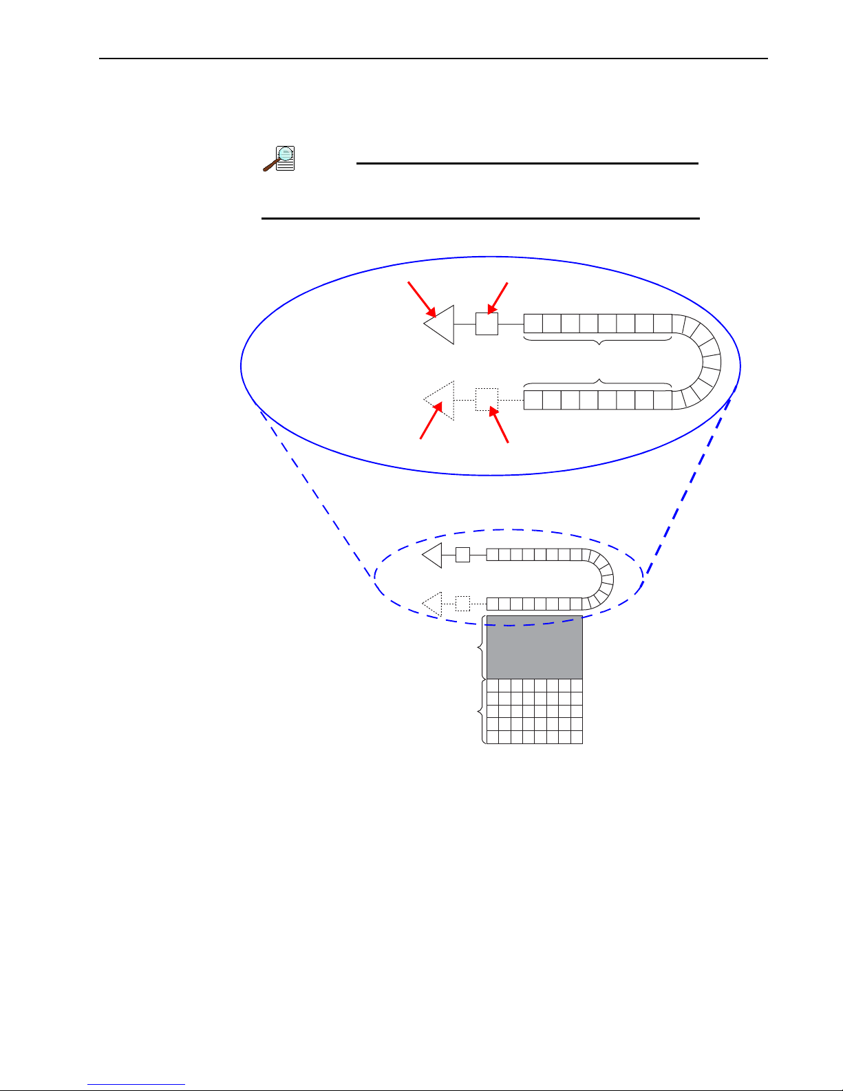
Chapter 7 Exposure and Signal 89
NOTE:
4411-0149_0051
MULTIPLICATION GAIN
LOW NOISE
HIGH-SPEED LOW LIGHT
STANDARD, HIGH DYNAMIC
APPLICATIONS
RANGE APPLICATIONS
FRAME-TRANSFER AREA
SENSOR AREA
STANDARD SERIAL REGISTER
READOUT AMPLIFIER
NORMAL VOLTAGE CLOCK
HIGH VOLTAGE CLOCK
OUTPUT OR SENSOR NODE
EXTENDED MULTIPLICATION REGISTER
READOUT AMPLIFIER OUTPUT OR SENSOR NODE
7.10 Readout
ProEM-HS cameras use frame transfer CCDs with an equal number of active pixels as
frame transfer, or masked, pixels as illustrated in Figure 7-2.
Typically there are additional rows and columns for internal
reference.
Figure 7-2: EMCCD Array Structure
In standard frame transfer mode, the sensor area is exposed for specified time. The acquired
image data are then transferred to frame transfer area before reading the data out via the
multiplication gain register or standard serial register.
Regions of Interest (ROI) and/or binning can be used to improve the time resolution, limited
to a millisecond regime. For more information about the CCD exposure-readout operations,
refer to Section 7.10.6, Exposure - Readout Modes, on page 95.
WinX and LightField allow you to specify the type of readout (full frame or binned), the
output amplifier, and the gain (the number of electrons required to generate an ADU).
Page 90

90 ProEM-HS User Manual Issue 2
REFERENCES:
NOTE:
NOTE:
7.10.1 Dual-Readout Port Operation
The ProEM-HS camera is configured with software-selectable dual-readout amplifiers,
also referred to as ports. See Figure 7-2.
If the camera is configured with two readout amplifiers, the software automatically supports
port selection.
Refer to your application-specific user manual for information
about readout amplifier/port selection. Refer to Tab le 1-1 for
specific document numbers and titles.
The two amplifiers/ports are:
• Multiplication Gain {Electron Multiplied}
When this port is selected, the EM gain value can be configured on the
Setup —> Main
tab {Analog to Digital Conversion expander}. Since the
multiplication gain can be used to overcome the read noise of the fast amplifier, this
mode is most useful in applications requiring low-light sensitivity at high frame
rates (e.g., Single molecule fluorescence, ion imaging, etc.). Only 25x - 100x EM
gain is required to overcome the read noise of the camera. Using excessive EM gain
will not improve the overall signal to noise ratio (SNR).
Experiment
An image read out of the Multiplication Gain {Electron
Multiplied} port is the mirror image of the same image read out
of the Low Noise port. Unless the application software
automatically corrects the orientation when the selected port
changes, it may be necessary to specify that the image be
flipped horizontally.
• Low Noise
When the camera is using this amplifier, electrons (i.e., signal,) generated in pixels
are clocked through the standard serial register. The amplifier is designed to take
advantage of the dynamic range of the CCD and is most useful when the frame rate
is not critical. (e.g., bright field, fixed cell fluorescence, etc.)
An image read out of the Low Noise port is the mirror image of
the same image read out of the Multiplication Gain {Electron
Multiplied} port. Unless the application software automatically
corrects the orientation when the selected port changes, it may
be necessary to specify that the image be flipped horizontally.
Page 91

Chapter 7 Exposure and Signal 91
7.10.2 Controller Gain {Analog Gain}
Controller Gain {Analog Gain} is software-selectable and is used to change the relationship
between the number of electrons acquired on the CCD and the Analog-to-Digital Units
(ADUs, or counts,) generated.
Selecting the amount of gain is done on the
tab {
Analog to Digital Conversion expander}.
Valid settings are:
• 1 {Low}
This setting is suitable for applications where high-level signals are measured. This
option allows the digitization of larger signals.
• 2 {Medium}
This setting is suitable for experiments within the mid-level intensity range.
• 3 {High}.
This setting is suitable for applications where low-level signals are continually
measured. This selection requires fewer electrons to generate an ADU and reduces
some sources of noise.
Table 7-3 summarizes typical controller gain values for a ProEM-HS camera.
Table 7-3: Typical Controller Gains
Acquisition —> Experiment Setup… —> ADC
Typical Gain
Readout Amplifier (Port)
Setting
Multiplication Gain {Electron Multiplied} 1 {Low} 12
2 {Medium} 6
3 {High} 3
Low Noise 1 {Low} 3.2
2 {Medium} 1.6
3 {High} 0.8
(e-/ADU)
The Certificate of Performance supplied with each ProEM-HS camera lists the measured
gain values at all settings.
Page 92

92 ProEM-HS User Manual Issue 2
REFERENCES:
NOTES:
7.10.3 Readout Rate
Refer to Table A-1, CCD Array Specifications, on page 157 for
specific readout rates for each ProEM-HS camera.
The Low Noise readout port is ideal when high speed acquisition is not required and/or long
integration times can be used to build up the signal. Lower readout speeds (e.g., 100 kHz,)
and lack of excess noise in this mode offers better signal to noise ratio when high frame rate
is not required.
Conversely, increased frame readout rate can be achieved by implementing a number of
techniques, including:
• Higher readout speed;
• Subregion selection;
• Binning.
7.10.4 Regions of Interest (ROI)
A Region of Interest (ROI) may be defined as an entire CCD array or it may be a
rectangular subregion of the array.
An ROI is defined in the X and Y direction by:
• A start pixel;
• An end pixel;
• A group/height (binning) factor.
After one or more regions have been defined and stored, the data acquisition software uses
these regions to determine which information is to be read out and displayed, and which
information is to be discarded.
1. For Flatfield Correction, Background Subtraction, etc., the
images must be exactly the same size.
2. References to X and Y axes assume that the shift register is
parallel to the X-axis and that the data are shifted to the
shift register in the Y direction.
3. Depending on the data acquisition software being used, the
horizontal axis may be called X or Wavelength.
Page 93

Chapter 7 Exposure and Signal 93
CAUTION!
!
7.10.4.1 LightField
The configuration of ROIs is done on the
Region of Interest expander.
When ROIs are used to acquire data, configuration information for all defined ROIs is
stored in the data file when the data are saved. The information for the active data display
can be reviewed using the
Viewer —> Data Options
Show File Information function accessed from the Comparison
menu.
7.10.4.2 WinX/32
Depending on the size of the ROI to be defined, it can be configured in one of two ways:
• The Easy Bin dialog;
This is accessed from the menu bar by selecting
Acquisition —> Easy Bin.
This is the simplest method of defining a single full-chip-width ROI.
• The ROI Setup tab,
This is accessed from the menu bar by selecting
Setup
.
Acquisition —> Experiment
ROI Setup allows ROIs to be created with greater flexibility in chip location and
width.
When ROIs are used to acquire data, configuration information for the first 10 ROIs is
stored in the data file when the data are saved. The information for the active data display
can be reviewed using the
Display Context menu.
File Information function accessed from either the File or
7.10.4.3 WinX/32 Examples
The following examples include partial frame ROIs with and without binning.
•X Start to End = 200 pixels, no grouping (binning).
Since 200/4=50, this is a valid ROI setup.
•X Start to End = 200 pixels and grouping (binning) is by 8.
The resulting number of super pixels is 25. Since 25/4=6.25, this is not a valid ROI
setting for the horizontal direction in WinX. However, this setting would be valid in
LightField.
•X Start to End = 240 pixels, no grouping (binning).
Since 240/4=60 this is a valid ROI setup.
•X Start to End = 240 pixels and grouping (binning) is by 3.
The resulting number of super pixels is 80. Since 80/4=20, this is a valid ROI setup.
•X Start to End = 240 pixels and grouping (binning) is by 16.
The resulting number of super pixels is 15. Since 15/4=3.75, this is not a valid ROI
setting for the horizontal direction in WinX. However, this setting would be valid in
LightField.
When configuring a partial frame ROI, the number of pixels in
the serial (horizontal) direction must be evenly divisible by 4,
even after binning.
Page 94
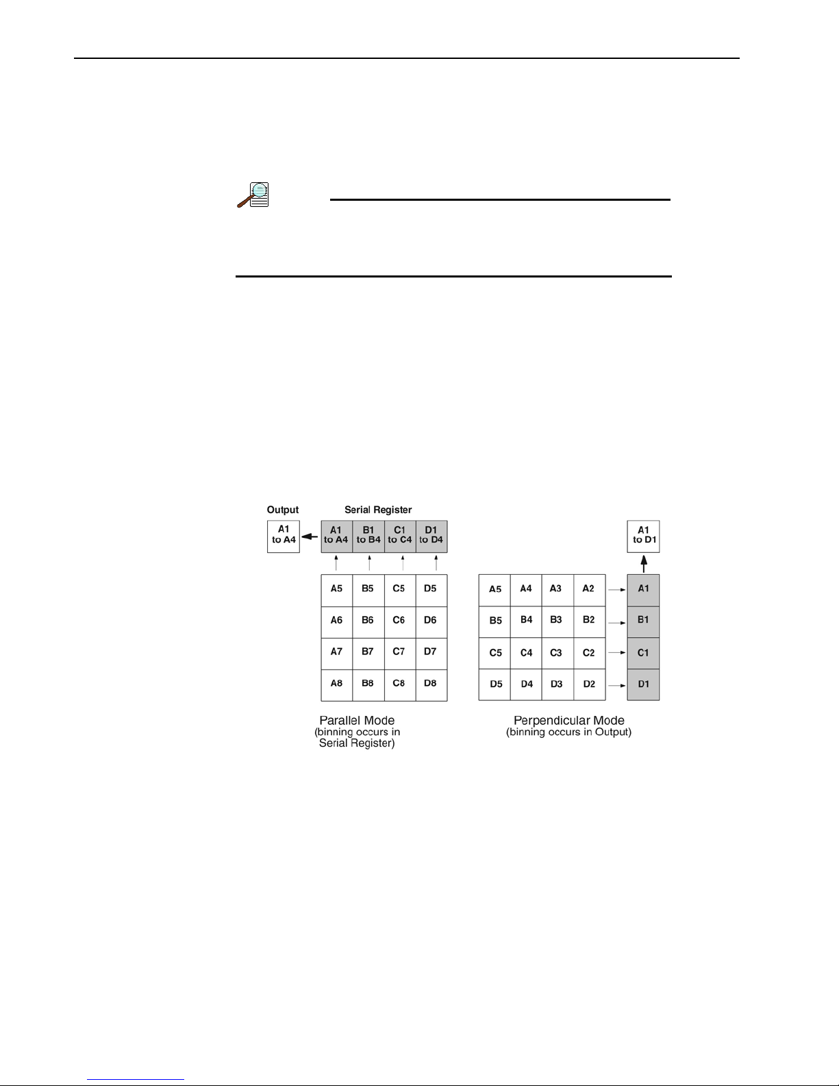
94 ProEM-HS User Manual Issue 2
NOTE:
7.10.5 Binning
Binning is the process of combining multiple pixels into one super pixel and can increase
sensitivity and frame rate. Conversely, binning also reduces spatial resolution.
The ProEM-HS supports flexible vertical binning as well as binning of 2x – 32x in the
horizontal direction.
When binning in WinX/32, the resulting number of super
pixels in the horizontal direction must be evenly divisible by 4.
This constraint does not apply to LightField.
7.10.5.1 Array Orientation
ProEM-HS cameras use square CCDs. Therefore, binning can be performed along either
direction of the CCD.
• Binning along columns (parallel mode) provides increased scan rates and improved
Signal-to-Noise Ratio (SNR.)
• Binning along the rows (perpendicular mode) minimizes crosstalk and is therefore
better for multi-spectral applications. The drawback to this method is that scanning
is slower and noise may increase somewhat.
See Figure 7-3.
Figure 7-3: Binning and Array Orientation
Switch between these orientations is easily achieved by rotating the camera 90° and
changing the binning parameters within the application software.
Page 95

Chapter 7 Exposure and Signal 95
NOTE:
REFERENCES:
NOTE:
7.10.6 Exposure - Readout Modes
The frame transfer CCD used by the ProEM-HS supports the following readout modes:
• Frame Transfer;
• Full Frame/sequential;
• Kinetics;
• Spectra-Kinetics.
When using Frame Transfer mode, be aware that the set
exposure time may not be the effective exposure time.
Kinetics and Spectra-Kinetics are typically options for the
frame transfer ProEM-HS cameras. For additional information
about these readout modes, refer to:
• Chapter 9, Kinetics Mode, on page 109;
• Section 9.6, Spectra-Kinetics Option, on page 118.
7.10.6.1 Frame Transfer Mode (Simultaneous Exposure-Readout)
Frame Transfer mode is extremely useful in applications requiring continuous imaging (i.e.,
100% duty cycle.) Once a frame has been exposed and transferred into the frame transfer
area, the next exposure starts immediately and continues until the previous frame has been
read out of the frame transfer area or until the exposure time has finished, whichever is
longer.
The minimum effective exposure time for this mode is the
readout time.
This mode of operation allows a specimen to be continuously imaged in order to obtain
better kinetic information about a process.
In both WinX/32 and LightField, Frame Transfer is the default mode of operation for
cameras with frame transfer CCDs. If necessary, the readout mode can be changed on the
Hardware Setup/Controller/Camera tab {Sensor expander}.
The simultaneous exposure-readout mechanism is illustrated in the following examples.
Page 96

96 ProEM-HS User Manual Issue 2
NOTE:
TIMING INFORMATION IS FOR ILLUSTRATION PURPOSE ONLY.
S
PECIFIC READOUT TIMES VARY DEPENDING ON THE MODEL.
Example 1: Frame Transfer Mode when Exposure Time < Readout Time
Consider an application where full frame readout is 30 ms, the exposure time is 10 ms, and
three frames are acquired in Frame Transfer mode.
The first frame is exposed precisely for the length of time entered into the software (i.e.,
10 ms,) and all subsequent frames are exposed for the readout time.
The total time necessary to acquire 3 frames is then:
(3 30ms) + 10ms = 100 ms
This is equivalent to a frame rate of 33.33 fps (i.e., 3 frames 0.100 seconds.)
Because the first frame is exposed for 10 ms and the others for
30 ms, the first frame may appear dimmer when compared
with the other frames that have been acquired.
In Frame Transfer mode when exposure time < readout time, the total time (T
) required to
N
capture N frames is calculated using the formula:
T
= (t
N) + t
N
R
exp
Where:
• T
• t
• N = total number of frames in a sequence
• t
= Total time required to capture a sequence of N frames
N
= readout time for one frame
R
= exposure time
exp
Figure 7-4 illustrates a typical timing diagram.
Figure 7-4: Frame Transfer Mode Timing Diagram: Exposure Time < Readout Time
Page 97

Chapter 7 Exposure and Signal 97
TIMING INFORMATION IS FOR ILLUSTRATION PURPOSE ONLY.
S
PECIFIC READOUT TIMES VARY DEPENDING ON THE MODEL.
Example 2: Frame Transfer Mode when Exposure Time > Readout Time
If the exposure time is set to 50 ms with the readout time remaining at 30 ms, the time
required to acquire three frames is:
(3 50 ms) + 30 ms = 180 ms
This is equivalent to a frame rate of 16.67 fps.
In Frame Transfer mode when exposure time > readout time, the total time (T
) required to
N
capture N frames is calculated using the formula:
= (t
T
N
exp
N) + t
R
Where:
• T
• t
• N = total number of frames in a sequence
• t
= Total time taken to capture a sequence of N frames
N
= exposure time
exp
= readout time for one frame
R
From the timing diagram shown in Figure 7-5, it can be seen that because the exposure time
is greater than the readout time, all frames are precisely exposed for the duration entered
into the software and have similar intensities.
Figure 7-5: Frame Transfer Mode Timing Diagram: Exposure Time > Readout Time
Page 98

98 ProEM-HS User Manual Issue 2
NOTE:
7.10.6.2 Full Frame (Sequential) Mode for Frame-Transfer EMCCD
Full Frame mode allows an array to be exposed for the exposure time specified in the
software and is similar in performance to a normal, full-frame CCD device. See Figure 7-6.
Figure 7-6: Typical EMCCD Array Structure
The operational sequence for this mode is:
1. Clean the CCD.
2. Expose for the specified exposure time.
3. Shift the image from the sensor area to the frame-transfer area.
4. Read out the CCD.
These four steps are repeated for each frame in a sequence. Both step 1 and step 3 require
minimal time and do not significantly affect the frame rate.
In WinX/32, Full Frame mode is selected from
Hardware Setup —> Controller/Camera
tab.
In LightField, Full Frame mode is selected on the
Example: Full Frame Mode for Frame-Transfer EMCCD
Sensor expander.
In this example, the exposure time is 10 ms and the readout time is 30 ms. The total time
required to acquire three frames is:
This is equivalent to a frame rate of 25 fps (i.e., 3 frames 0.120 seconds.
The exposure and readout times listed are for illustration
purpose only. Actual values may vary. Refer to the ProEM-HS
data sheet for actual readout times.
As shown in Figure 7-7, exposure and readout are carried out in a sequential fashion. As a
result, each frame in the sequence is precisely exposed for the time specified (i.e., 10 ms.)
Figure 7-7 illustrates the timing diagram when operating in Full Frame mode.
(3 10 ms) + (3 30 ms) = 120 ms
Page 99

Chapter 7 Exposure and Signal 99
NOTE:
TIMING INFORMATION IS FOR ILLUSTRATION PURPOSE ONLY.
S
PECIFIC READOUT TIMES VARY DEPENDING ON THE MODEL.
Figure 7-7: Timing Diagram: Full Frame Mode
7.10.6.3 Full Frame Readout for Full Frame EMCCD
In Figure 7-8, the diagram in the upper-left corner represents a full frame EMCCD after
exposure but before the beginning of readout. The capital letters represent different amounts
of charge, including both signal and dark charge. This section explains readout at full
resolution, where every pixel is digitized separately. In this drawing, the charge is being
read out of the Low Noise port.
The Multiplication {Electron Multiplied} port is not shown in
this drawing.
Figure 7-8: Full Frame at Full Resolution
Page 100

100 ProEM-HS User Manual Issue 2
Readout of the CCD begins with the simultaneous shifting of all pixels one row toward the
“shift register,” in this case the row on the top. The shift register is a single line of pixels
along the edge of the EMCCD, not sensitive to light and used for readout only. Typically the
shift register pixels hold twice as much charge as the pixels in the imaging area of the CCD.
After the first row is moved into the shift register, the charge now in the shift register is
shifted toward the output node, located at one end of the shift register. As each value is
“emptied” into this node it is digitized. Only after all pixels in the first row are digitized is
the second row moved into the shift register. The order of shifting in our example is
therefore A1, B1, C1, D1, A2, B2, C2, D2, A3.... After charge is shifted out of each pixel,
the remaining charge is zero, meaning that the array is immediately ready for the next
exposure.
A subsection of the CCD can be read out at full resolution, sometimes dramatically
increasing the readout rate while retaining the highest resolution in the region of interest
(ROI).
7.10.7 Readout Time
Readout time is calculated based on the current ROI/Binning/Vertical shift rate settings.
• In WinX/32, Readout Time is viewed by going to the Acquisition menu and
selecting
• In LightField, Readout Time is reported on the Sensor expander.
Readout Time….
 Loading...