

Page 1

4411-0133
Version 2
November 15, 2013
*4411-0133*
Page 2

Copyright 2011-2013 Princeton Instruments, a division of Roper Scientific, Inc.
3660 Quakerbridge Rd
Trenton, NJ 08619
TEL: 800-874-9789 / 609-587-9797
FAX: 609-587-1970
All rights reserved. No part of this publication may be reproduced by any means without the written
permission of Princeton Instruments, a division of Roper Scientific, Inc. ("Princeton Instruments").
Printed in the United States of America.
IntelliCal and PICam are trademarks, and LightField and PVCAM are registered trademarks of Roper
Scientific, Inc.
LabVIEW is a registered trademark of National Instruments, Inc.
LEMO is a registered trademark of INTERLEMO HOLDING SA
Scientific Imaging ToolKit and SITK are trademarks of R Cubed Software Consultants, LLC.
SpectraPro is a trademark of Acton Research Corporation.
UNIBLITZ is a registered trademark of VA, Inc. Corporation
Windows and Windows Vista are registered trademarks of Microsoft Corporation in the United States
and/or other countries.
The information in this publication is believed to be accurate as of the publication release date. However,
Princeton Instruments does not assume any responsibility for any consequences including any damages
resulting from the use thereof. The information contained herein is subject to change without notice.
Revision of this publication may be issued to incorporate such change.
Page 3

Table of Contents
Chapter 1 Introduction .........................................................................................7
PIXIS-XB ..................................................................................................................... 7
Advanced Design ......................................................................................................... 7
Grounding and Safety ................................................................................................... 7
Precautions ................................................................................................................... 8
Cleaning ....................................................................................................................... 8
Repairs .......................................................................................................................... 9
Princeton Instruments Customer Support ..................................................................... 9
About this Manual ........................................................................................................ 9
Chapter 2 System Component Descriptions .................................................. 11
System Components ................................................................................................... 11
PIXIS-XB Camera ...................................................................................................... 12
PIXIS-XB Power Supply............................................................................................ 13
Coolant Hoses (Liquid-cooled Systems) .................................................................... 14
Cables ......................................................................................................................... 14
Certificate of Performance ......................................................................................... 14
User Manuals .............................................................................................................. 14
Optional Components ................................................................................................. 15
Chapter 3 Initial System Verification ............................................................... 17
Chapter 4 System Setup ................................................................................... 19
Introduction ................................................................................................................ 19
Unpacking the System ................................................................................................ 19
Checking the Equipment and Parts Inventory ............................................................ 20
System Requirements ................................................................................................. 20
Installing the Application Software ............................................................................ 22
Mounting the Camera ................................................................................................. 24
Making the Camera-Circulator Connections for a CoolCUBEII ................................ 25
Entering the Default Camera System Parameters ...................................................... 26
Connecting an External Shutter .................................................................................. 28
Connecting/Disconnecting the PIXIS-XB USB Cable ............................................... 28
Chapter 5 Operation .......................................................................................... 29
Introduction ................................................................................................................ 29
System On/Off Sequences .......................................................................................... 30
WinX First Light Instructions .................................................................................... 30
LightField First Light Instructions ............................................................................. 33
Exposure and Signal ................................................................................................... 36
Readout....................................................................................................................... 39
Digitization (Rate) ...................................................................................................... 44
iii
Page 4

iv PIXIS-XB System Manual Version 2
Chapter 6 Advanced Topics ............................................................................. 47
Introduction ................................................................................................................ 47
Timing Modes ............................................................................................................ 48
Fast and Safe Modes................................................................................................... 54
LOGIC OUT Control ................................................................................................. 56
Kinetics Mode ............................................................................................................ 57
Custom Modes ............................................................................................................ 60
Chapter 7 Troubleshooting .............................................................................. 63
Introduction ................................................................................................................ 63
Acquisition Started but Viewer Contents Do Not Update .......................................... 64
Baseline Signal Suddenly Changes ............................................................................ 64
Camera Stops Working .............................................................................................. 64
Camera1 (or similar name) in Camera Name field .................................................... 65
Controller Is Not Responding..................................................................................... 66
CoolCUBEII: Low Coolant (Air in the Hoses) ........................................................... 66
Cooling Troubleshooting ............................................................................................ 67
Data Loss or Serial Violation ..................................................................................... 68
Data Overrun Due to Hardware Conflict message ..................................................... 68
Data Overrun Has Occurred message......................................................................... 69
Device Is Not Found................................................................................................... 69
Device is Occupied ..................................................................................................... 70
Error Creating Controller message ............................................................................. 70
Overexposed or Smeared Images ............................................................................... 70
Program Error message .............................................................................................. 71
Serial violations have occurred. Check interface cable. ............................................. 72
Shutter Failure ............................................................................................................ 72
Vignetting ................................................................................................................... 72
Declaration of Conformity ................................................................................ 73
Appendix A Basic Specifications .................................................................... 75
CCD Arrays ................................................................................................................ 75
Quantum Efficiency ................................................................................................... 75
Camera ....................................................................................................................... 76
Options ....................................................................................................................... 77
Appendix B Outline Drawings .......................................................................... 79
PIXIS-XB Camera ...................................................................................................... 79
Customer-Supplied Vacuum Interface Flange: Minimum Design
Requirements .............................................................................................................. 83
CoolCUBEII Circulator ............................................................................................... 84
Appendix C Cross-Referencing of WinX and LightField Terms ...................... 85
WinX-to-LightField.................................................................................................... 85
LightField-to-WinX.................................................................................................... 87
Page 5

Table of Contents v
Warranty & Service ........................................................................................... 89
Limited Warranty ....................................................................................................... 89
Contact Information ................................................................................................... 92
Index ................................................................................................................... 93
Figures
Figure 1. Typical System Components ............................................................................ 11
Figure 2. Initial System Checkout Imaging Experiment Layout (Air-cooled Camera) ... 18
Figure 3. Initial System Checkout Imaging Experiment Layout (Liquid-cooled Camera) ... 18
Figure 4. WinView Installation: Select Installation Type dialog .................................... 22
Figure 5. LightField Installation Wizard dialog .............................................................. 23
Figure 6. Position of Camera Mounting Hole .................................................................. 24
Figure 7. Camera Detection Wizard - Welcome dialog ................................................... 26
Figure 8. LightField Experiment Workspace................................................................... 27
Figure 9. Block Diagram of PIXIS-XB System .............................................................. 29
Figure 10. Initial System Checkout Imaging Experiment Layout ................................... 30
Figure 11. Example of WinView Data Acquired from First Light Procedure ................. 33
Figure 12. Available Devices Area .................................................................................. 34
Figure 13. Experiment Devices Area ............................................................................... 35
Figure 14. View Area....................................................................................................... 35
Figure 15. View Area Displaying an Image .................................................................... 36
Figure 16. Mechanical Shutter Operation and NOT SCAN Signal ................................. 37
Figure 17. WinX Detector Temperature dialog .............................................................. 37
Figure 18. Array Terms for a CCD with a Dual Output Amplifier ................................. 39
Figure 19. Full Frame at Full Resolution ......................................................................... 39
Figure 20. 2 × 2 Binning .................................................................................................. 41
Figure 21. Binning and Array Orientation ....................................................................... 42
Figure 22. Free Run {No Response} Timing Chart, part of the chart in Figure 30 ......... 49
Figure 23. Free Run {No Response} Timing Diagram.................................................... 49
Figure 24. Chart Showing Two External Sync Timing Options ...................................... 50
Figure 25. Timing Diagram for External Sync Mode (+ edge trigger) ............................ 51
Figure 26. Continuous Cleans {Clean Until Trigger} Flowchart .................................... 52
Figure 27. WinX Continuous Cleans Timing Diagram ................................................... 53
Figure 28. LightField Clean Until Trigger (CUT) Timing Diagram ............................... 53
Figure 29. Rear of PIXIS-XB Camera ............................................................................. 53
Figure 30. Chart of Safe and Fast Mode Operation ......................................................... 55
Figure 31. Comparison of NOT SCAN {Not Reading Out}, SHUTTER
{Shutter Open}, and NOT READY {Busy} Logic Output Levels ............... 56
Figure 32. Kinetics Readout ............................................................................................ 57
Figure 33. Hardware Setup dialog ................................................................................... 58
Figure 34. Experiment Setup dialog ................................................................................ 58
Figure 35. Readout expander: Kinetics Readout Mode .................................................. 58
Figure 36. Shutter and Trigger expanders........................................................................ 58
Figure 37. Free Run Timing Diagram.............................................................................. 59
Figure 38. Single Trigger Timing Diagram ..................................................................... 59
Figure 39. Multiple Trigger Timing Diagram.................................................................. 60
Figure 40. WinX: Custom Chip tab ................................................................................. 61
Figure 41. LightField: Custom Sensor pane .................................................................... 61
Figure 42. LightField: Custom Timing ............................................................................ 62
Page 6

vi PIXIS-XB System Manual Version 2
Figure 43. WinX: Vertical Shift ...................................................................................... 62
Figure 44. Acquisition Display ........................................................................................ 64
Figure 45. Camera1 in Camera Name Field .................................................................... 65
Figure 46. Data Overrun Due to Hardware Conflict dialog ............................................. 68
Figure 47. Devices Missing dialog .................................................................................. 69
Figure 48. Occupied Device icon ................................................................................... 70
Figure 49. Error Creating Controller dialog .................................................................... 70
Figure 50. Program Error dialog ...................................................................................... 71
Figure 51. Serial Violations Have Occurred dialog ......................................................... 72
Figure 52. PIXIS-XB Quantum Efficiency Curve ........................................................... 75
Figure 53. PIXIS-XB:400 and 1024 (Air-Cooled) .......................................................... 79
Figure 54. PIXIS-XB:400 and 1024 (Liquid-Cooled) ..................................................... 80
Figure 55. PIXIS-XB:1300 and 2048 (Air-Cooled) ........................................................ 81
Figure 56. PIXIS-XB:1300 and 2048 (Liquid-Cooled) ................................................... 82
Figure 57. Dimensional Drawing for Customer-Supplied Vacuum Interface Flange ..... 83
Figure 58. CoolCUBEII Circulator ................................................................................... 84
Tables
Table 1. USB Driver Files and Locations ........................................................................ 22
Table 2. Example of Controller Gain {Analog Gain} vs. Readout Port .......................... 43
Table 3. Camera Timing Modes ...................................................................................... 48
Table 4. Typical Deepest Operating Temperature ........................................................... 77
Page 7

Chapter 1
WARNING!
Introduction
PIXIS-XB
Thank you for purchasing a PIXIS-XB camera system
from Princeton Instruments. For over three decades
Princeton Instruments has been the legendary name behind
the most revolutionary spectroscopy and imaging products
for cutting edge research.
Among the many state of the art features are its integrated
controller, deep thermoelectric air-cooling, and compact
design. Currently the platform supports several imaging and spectroscopy CCDs. Please
visit www.princetoninstruments.com for the current list of supported CCDs.
Advanced Design
PIXIS-XB systems are designed specifically for applications like X-ray photon
correlation spectroscopy (XPCS), X-ray intensity fluctuation spectroscopy (XIFS), X-ray
diffraction, X-ray lithography, and X-ray spectroscopy. These cameras use deepdepletion CCDs for direct detection of X-rays between < 3 keV and 20 keV. A thin
beryllium window in front vacuum seals the unit for deep cooling, protects the CCD, and
reduces background by filtering low-energy X-rays. The thermoelectrically-cooled option
delivers maintenance-free operation. The software-selectable gains, output amplifiers,
and readout speeds offer users highly flexible configuration capabilities to optimize
system performance. USB 2.0 electronics provide the plug-and-play interface with the host
computer.
To utilize the full potential of the PIXIS-XB camera system, please read the manual
completely.
Grounding and Safety
Before turning on the power supply (air-cooled system or liquid-cooled system with a
CoolCUBEII circulator), the ground prong of the power cord plug must be properly
connected to the ground connector of the wall outlet. The wall outlet must have a third
prong, or must be properly connected to an adapter that complies with these safety
requirements.
If the equipment is damaged, the protective grounding could be disconnected. Do not use
damaged equipment until its safety has been verified by authorized personnel.
Disconnecting the protective earth terminal, inside or outside the apparatus, or any
tampering with its operation is also prohibited.
Inspect the supplied power cord. If it is not compatible with the power socket, replace the
cord with one that has suitable connectors on both ends.
7
Page 8

8 PIXIS-XB System Manual Version 2
WARNING!
WARNING!
Replacement power cords or power plugs must have the same polarity and power rating
as that of the original ones to avoid hazard due to electrical shock.
Precautions
To prevent permanently damaging the system, please observe the following precautions:
The CCD array is very sensitive to static electricity. Touching the CCD can
destroy it. Operations requiring contact with the device can only be performed at
the factory.
If you are using high-voltage equipment (such as an arc lamp) with your camera
system, be sure to turn the camera power ON LAST and turn the camera power
OFF FIRST.
Use caution when triggering high-current switching devices (such as an arc lamp)
near your system. The CCD can be permanently damaged by transient voltage
spikes. If electrically noisy devices are present, an isolated, conditioned power
line or dedicated isolation transformer is highly recommended.
Do not block air vents on the camera. Preventing the free flow of air overheats
the camera and may damage it.
Cleaning
If the PIXIS-XB camera system is used in a manner not specified by Princeton
Instruments, the protection provided by the equipment may be impaired.
Turn off all power to the equipment and secure all covers before cleaning the units.
Otherwise, damage to the equipment or injury to you could occur.
Camera
Although there is no periodic maintenance that needs to be performed on a PIXIS-XB
camera, users are advised to wipe it down with a clean damp cloth from time to time. This
operation should only be done on external surfaces other than the Beryllium window (water
can damage the window), all covers must be secured, and the camera must powered off. In
dampening the cloth, use clean water only. No soap, solvents or abrasives should be used. Not
only are they not required, but they could damage the finish of the surfaces on which they are
used.
Beryllium Window
Cleaning may be necessary to remove oil or other contaminants from the surface of the
window. Because a fingerprint left on the surface will disrupt the effectiveness of the
final etch or coating and because of the potential toxicity, protective gloves should be
worn when cleaning the window. To clean the window, wipe it down with isopropanol
and a lintless cloth. DO NOT use water. Beryllium is highly susceptible to localized
pitting when in contact with the chloride and sulfate ions contained in ordinary water.
Page 9

Chapter 1 Introduction 9
Repairs
Save the original packing materials. Because the PIXIS-XB camera system contains no
user-serviceable parts, Princeton Instruments must do repairs. Should your system need
repair, contact Princeton Instruments Customer Support for instructions (telephone,
e-mail, and address information are provided on page 92 of this manual).
Use the original packing materials whenever shipping the system or system components.
Princeton Instruments Customer Support
Refer to the contact information located on page 92 of this manual.
About this Manual
Manual Organization
This manual provides the user with all the information needed to install a PIXIS-XB
camera and place it in operation. Topics covered include detailed description of the
cameras in the PIXIS-XB family, installation, applications, cleaning, specifications and
more.
Notes:
1. "WinX" is a generic term for WinView/32, WinSpec/32, and WinXTest application
software.
2. In many instances, WinX and LightField use different terms for the same functions or
parameters. Unless the topic is specifically for WinX or LightField, curly brackets
{ } are used to denote a LightField term or location. When the topic applies to both
application programs, the WinX term will be followed by the {LightField term}: for
example, when Continuous Cleans is used, it will be followed by {Clean Until
Trigger}. This convention is also used when a location for setting a parameter is
mentioned: for example, Exposure Time is set on the Experiment Setup|Main tab
{Common Acquisition Settings expander}.
Chapter 1, Introduction provides an overview of the PIXIS-XB cameras.
Chapter 2, System Component Descriptions provides information about the
camera, interface card, cables and application software.
Chapter 3, Initial System Verification cross-references system setup actions
with the relevant manuals and/or manual pages. It also contains system layout
diagrams.
Chapter 4, System Setup provides detailed directions for setting up the camera
for imaging applications and presents over-exposure protection considerations.
Chapter 5, Operation includes step-by-step procedures for verifying system
operation and discusses operational considerations associated with exposure,
readout, and digitization.
Chapter 6, Advanced Topics discusses standard timing {Trigger Response}
modes (Free Run {No Response}, External Sync {Readout Per Trigger}, and
Continuous Cleans {Clean Until Trigger}), Fast and Safe modes, Logic Output
control, Kinetics mode, and Custom modes.
Page 10

10 PIXIS-XB System Manual Version 2
Caution! The use of this symbol on equipment indicates that one or
more nearby items should not be operated without first consulting the
manual. The same symbol appears in the manual adjacent to the text
that discusses the hardware item(s) in question.
Warning! Risk of electric shock! The use of this symbol on
equipment indicates that one or more nearby items pose an electric
shock hazard and should be regarded as potentially dangerous. This
same symbol appears in the manual adjacent to the text that discusses
the hardware item(s) in question.
Chapter 7, Troubleshooting provides courses of action to take if you should
have problems with your system.
Appendix A, Specifications includes camera specifications.
Appendix B, Outline Drawings includes outline drawings of the camera and the
CoolCUBEII circulator.
Appendix C, Cross-Referencing of WinX and LightField Terms includes
two alphabetically sorted tables (WinX to LightField and LightField to WinX)
that cross reference terms used in the two applications.
Declaration of Conformity contains the Declaration of Conformity for PIXIS-XB
systems.
Warranty & Service contains the warranty and customer support contact
information.
Safety Related Symbols Used in this Manual
Page 11

Chapter 2
System Component Descriptions
System Components
Standard Components
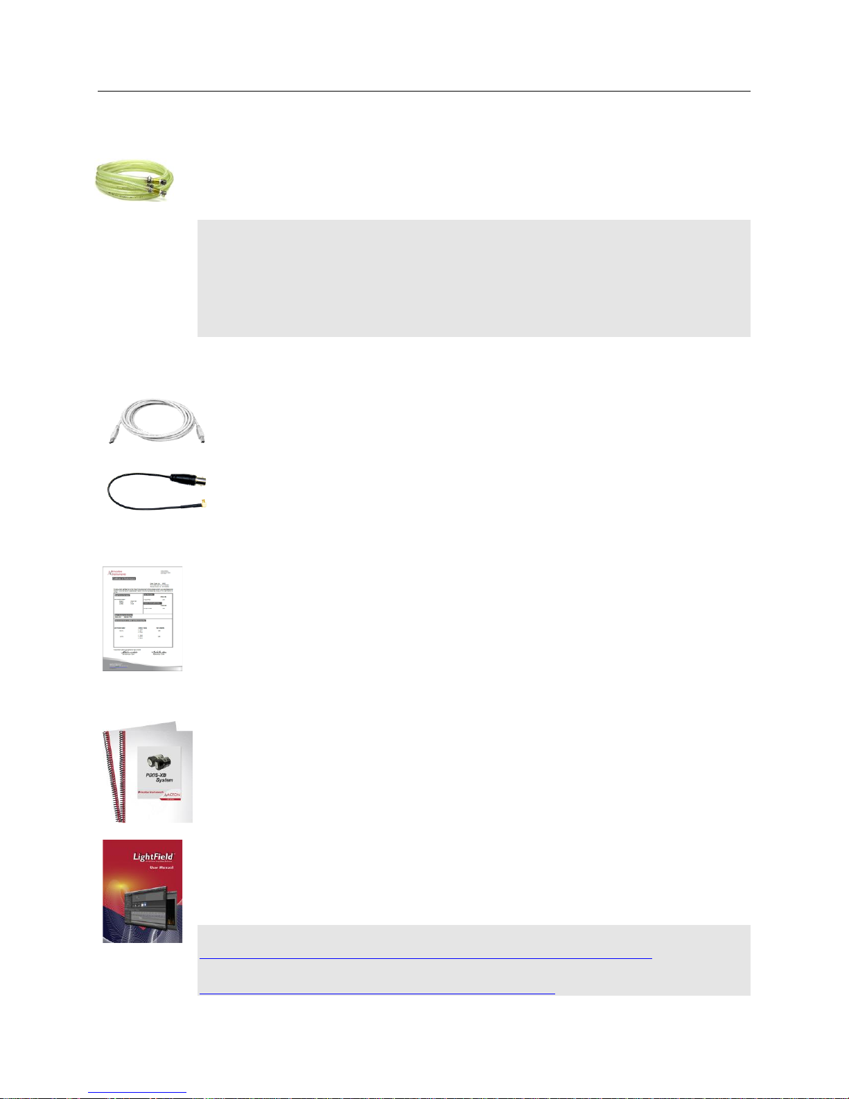
A typical air-cooled PIXIS-XB system consists of the camera with a Certificate of
Performance, a power supply, a USB 2.0 interface cable for your computer system, MCX
to BNC adapter cables, and the user manual. A typical liquid-cooled PIXIS-XB system
consists of the camera with a Certificate of Performance, a CoolCUBEII circulator with
hoses, a USB 2.0 interface cable for your computer system, MCX to BNC adapter cables,
and the user manual.
Optional System Components
Optional items include the WinX application software and manual, LightField application
software and manual, and Scientific Imaging ToolKit™ (SITK™) for LabVIEW®.
11
Figure 1. Typical System Components
Page 12

12 PIXIS-XB System Manual Version 2
PIXIS-XB Camera
CCD Array: The PIXIS-XB camera system offers back-illuminated, deep-depletion CCDs as
well as a front-illuminated, deep-depletion CCD (PIXIS:1300R). The variety of array
sizes allows you to precisely match the sensor to your application. Only scientific-grade
devices are used in order to ensure the highest image fidelity, resolution, and acquisition
flexibility required for scientific X-ray imaging and spectroscopy. Princeton Instruments
has developed exclusive CCDs with unmatched quantum efficiency and low noise to
offer the utmost in sensitivity. Large full wells, square pixels, and 100% fill factors
provide high dynamic range and excellent spatial resolution. Your choice of CCD is
already installed in the camera that you received and has been individually tested.
Cooling: Dark current is reduced in PIXIS-XB camera systems through thermoelectric
cooling of the CCD arrays. Cooling by this method uses a multi-stage Peltier cooler in
combination with air-circulation or circulating coolant. To prevent condensation and
contamination from occurring, cameras cooled this way should be mounted on a vacuum
chamber. Due to CCD size/packaging differences, the lowest achievable temperature can
vary from one PIXIS-XB model to the next. Please refer to the specific system’s data
sheet for cooling performance.
Connectors:
USB 2.0: Control signals and data are transmitted between the
camera and the host computer via the USB port located on the
rear of the camera. As of this printing, you can hot plug the
PIXIS-XB camera whenever the WinX application is not
running (i.e., connect or disconnect from the camera or the
host computer while the camera is powered ON). In the case
of cameras built before November 1, 2005, you must exit the
WinX application and turn the camera power OFF before
connecting the USB cable to or disconnecting it from the
camera or host computer.
Shutter: LEMO® connector provides the shutter drive pulses for driving a UNIBLITZ®
VS25 25 mm external shutter (small array cameras such as PIXIS-XB:400 and 1024) or a
UNIBLITZ CS45 45 mm external shutter (large array cameras such as PIXIS-XB:1300
and 2048). UNIBLITZ XRS6, XRS14, and XRS25 X-ray shutters are supported for
ONLY the large array cameras. Camera power must be OFF before connecting to or
disconnecting from this connector.
LOGIC OUT: 0 to +3.3V programmable logic level output (TTL-compatible). The
output of this connector can be programmed and can also be inverted via the
application software. For detailed information about each output signal, please see
“LOGIC OUT Control” (page 56).
EXT SYNC: 0 to +3.3V Logic level input (TTL-compatible) that has a 10 k pullup
resistor. Allows data acquisition and readout to be synchronized with external events.
Through software, positive or negative (default) edge triggering can be selected.
Power: Depending on the camera, the connector will be as follows:
DIN connector for PIXIS-XB:400 and 1024: 12 VDC (6.6A max) input from
power supply.
LEMO Connect for PIXIS-XB:1300 and 2048: 12 VDC (12.5A max) input
from power supply.
Page 13

Chapter 2 System Component Descriptions 13
Small Format PIXIS-XB: 400 and 1024
Maximum Power Output: 80 W
Input: 100-240 VAC, 47-63 Hz, 1.9A
Output: 12 VDC at 6.6 A maximum
Large Format PIXIS-XB: 1300 and 2048
Maximum Power Output: 150 W
Input: 100-240 VAC, 50/60 Hz, 2A
Output: 12 VDC at 12.5 A maximum
Fan: Air-cooled cameras contain an internal fan. Its purpose is:
to remove heat from the Peltier device that cools the CCD array and
to cool the electronics.
An internal Peltier device directly cools the cold finger on which the CCD is
mounted. The air drawn into the camera by the internal fan through the back slots on
the side panels and exhausted through the front slots on the side panels then removes
the heat produced by the Peltier device. The fan is always in operation and aircooling of both the Peltier and the internal electronics takes place continuously. The
fan is designed for low-vibration and does not adversely affect the image. For the fan
to function properly, free circulation must be maintained between the sides of the
camera and the laboratory atmosphere.
Coolant Ports: The camera coolant ports (located on side of the camera) are not
labeled. This is because coolant can flow through the camera in either direction. As is
the case with circulating air (see above), circulating coolant removes the heat
produced by the Peltier device. This means of heat removal is designed for vibrationfree data acquisition. For the circulating coolant to function properly, free air
circulation must be maintained between the sides of the CoolCUBEII and the
laboratory atmosphere. Use only the hoses and circulator shipped with your system.
Attaching any other hoses or circulator voids the warranty
PIXIS-XB Power Supply
The receptacle on the power supply should be compatible with the line-voltage line cords
in common use in the region to which the system is shipped. If the power supply
receptacle is incompatible, a compatible adapter should be installed on the line cord,
taking care to maintain the proper polarity to protect the equipment and assure user
safety.
Page 14
14 PIXIS-XB System Manual Version 2
USB 2.0 Cable: The standard 16.4' (5 m) cable (6050-0494) has USB connectors that
interconnect the "USB 2.0" connector on the rear of the PIXIS-XB with a USB card
installed in the host computer.
MCX to BNC Adapter Cables: Two MCX to BNC adapter cables are provided with
the PIXIS-XB system. These mount to the EXT SYNC and the LOGIC OUT connectors
on the rear of the PIXIS-XB.
Coolant Hoses (Liquid-cooled Systems)
Quick-disconnects that mate to the PIXIS-XB’s coolant ports have been installed on one
end of each hose. Refer to your coolant circulator’s specifications regarding circulator-
compatible hose fittings. If a Princeton Instruments CoolCUBE
circulator is ordered
II
with the camera, hoses are supplied with appropriate connectors on both ends.
Note: Part numbers for the hose, PIXIS-XB fittings, and CoolCUBEII fitting are:
McMaster# MCM 5238K748 (3/8 ID, 5/8 OD tubing);
CPC# MCD1004 (1/4 NPT Valved Coupling Body) and McMaster# MCM 5346K35
(barbed hose fitting adapter for 3/8" hose ID X 1/4" NPTF female pipe) at PIXIS end; and
CPC# NS6D17006 (3/8 hose barb valved in-line coupling body) at CoolCUBEII end.
Cables
Certificate of Performance
Each PIXIS-XB camera has a Certificate of Performance. This certificate states that the
camera system was assembled and tested according to approved Princeton Instruments
procedures. It documents the camera performance data as measured during the testing of
your PIXIS-XB and lists the Sales Order, Purchase Order, and Camera Serial numbers
(useful if you ever need to contact Princeton Instruments Customer Support).
User Manuals
PIXIS-XB System User Manual: This manual describes how to install and use the
PIXIS-XB system components.
WinView/32 or WinSpec/32 User Manual: This manual describes how to install and
use the application program. A PDF version of this manual is provided on the installation
CD. Additional information is available in the program's on-line help.
LightField® User Manual: This manual describes how to install and use the LightField
application program (for 64-bit Windows Vista
The manual is provided in PDF version on the installation CD and will be installed in the
Princeton Instruments/LightField/Documents subdirectory. Acrobat 7.0 or higher is
required. Additional information is available in the program's on-line help .
Note: You can download current versions of Princeton Instruments manuals at
ftp://ftp.princetoninstruments.com/Public/Manuals/Princeton Instruments/. The most
current versions of Acton manuals are located at
ftp://ftp.princetoninstruments.com/Public/Manuals/Acton/.
®
and Windows
®
7 operating systems).
Page 15

Chapter 2 System Component Descriptions 15
Optional Components
Application Software
WinX: The PIXIS-XB camera can be operated by using either WinView/32 or
WinSpec/32, Princeton Instrument's 32-bit Windows® software packages designed
specifically for high-end imaging and spectroscopy, respectively. The Princeton
Instruments' software provides comprehensive image/spectral capture and display
functions. The package also facilitates snap-ins to permit advanced operation. Using
the optional built-in macro record function, you can also create and edit your own
macros to automate a variety of operations. WinView and WinSpec take full
advantage of the versatility of the PIXIS-XB camera and even enhance it by making
integration of the detection system into larger experiments or instruments an easy,
straightforward endeavor.
PVCAM®: The standard software interface for cooled CCD cameras from Princeton
Instruments. It is a library of functions that can be used to control and acquire data
from the camera when a custom application is being written. For example, in the case
of Windows, PVCAM is a dynamic link library (DLL). Also, it should be understood
that PVCAM is solely for camera control and image acquisition, not for image
processing. PVCAM places acquired images into a buffer, where they can then be
manipulated using either custom written code or by extensions to other commercially
available image processing packages.
Scientific Imaging ToolKit™: SITK™ is a collection of LabVIEW® VIs for
scientific cameras and spectrographs. This third party software can be purchased
from Princeton Instruments.
LightField®: The PIXIS-XB can be operated using LightField, Princeton
Instrument’s 64-bit Windows Vista® and Windows® 7 compatible software package.
LightField combines complete control over Princeton Instruments’ cameras and
spectrographs with easy-to-use tools for experimental setup, data acquisition and
post-processing. LightField makes data integrity priority #1 via automatic saving to
disk, time stamping and retention of both raw and corrected data with full
experimental details saved in each file. LightField works seamlessly in multi-user
facilities, remembering each user’s hardware and software configurations and
tailoring options and features accordingly.
PICam™: The standard 64-bit software interface for cooled CCD cameras from
Princeton Instruments. PICam is an ANSI C library of camera control and data
acquisition functions. Currently, the interface supports Windows Vista and
Windows 7.
Note: PIXIS-XB may also be operated by several other third-party software
packages. Please check with the providers of the packages for compatibility and
support information.
Page 16

16 PIXIS-XB System Manual Version 2
Fiber Optic Extender Kit
The specially designed fiber optic data interface kit allows the computer and the USB2.0
camera head to be separated by up to 500 meters without the loss of data. The kit consists
of two compact, high speed transceivers (interface modules) for completely transparent
operation between the host computer and the camera. The FO kit is ideal for hazardous or
high EMI environments. This optional kit supports PIXIS, Spec-10, VersArray and
PI-MAX family of products as well Acton Series spectrographs with USB2.0 data
interface.
CoolCUBE
with PIXIS-compatible Hoses (PN 7567-0002)
II
Liquid-cooled PIXIS-XB cameras provide a low vibration system for data acquisition.
Instead of using a fan to remove heat, these cameras incorporate a closed loop system of
circulating fluid. The CoolCUBEII circulator unit continuously pumps the 50:50 mixture
of room temperature (23ºC) water and ethylene glycol. To prevent voiding the warranty,
use only the circulator and hoses shipped with your system.
Page 17

Chapter 3
Action
Reference
1. If the system components have not already been unpacked, unpack
them and inspect their carton(s) and the system components for
in-transit damage.
Chapter 4 System Setup,
page 19
2. Verify that all system components have been received.
Chapter 4 System Setup,
page 20
3. If the components show no signs of damage, verify that the
appropriate power cord has been supplied with the power supply.
Chapter 4 System Setup,
page 20
4. If the application software is not already installed in the host
computer, install it.
Chapter 4 System Setup,
page 22 & Software manual
5. If the USB2 interface card is not already installed in the host
computer, install it. Follow the manufacturer’s instructions
Manufacturer’s instructions
6. With the power supply disconnected from the camera, connect the USB
cable to the USB port at the rear of the camera and to the USB port at
the computer.
7. Air-Cooled System: Plug the power supply into the rear of the
camera and plug the power supply into the power source.
Liquid-Cooled System: Plug the power supply into the rear of the
camera and plug the power supply into the power source. Make the
hose connections to the camera. Plug the circulator into the power
source. Add coolant if necessary. Turn on the circulator.
Chapter 4 System Setup,
page 24
8. Turn the camera ON.
9. Turn on the computer and begin running the application software.
Software manual
10. Enter the hardware setup information or load the defaults from the
camera.
Chapter 5 Operation,
page 26
11. When the system reaches temperature lock, begin acquiring data in
focus mode.
Chapter 5 Operation,
page 32 or page 35
12. After verifying that the camera sees, turn the camera supply OFF. If
there is a circulator attached and running, turn it off as well.
Initial System Verification
The list and diagrams below briefly describe the sequence of actions required
to install your system and verify operation. Refer to the indicated references
for more detailed information.
17
Page 18

18 PIXIS-XB System Manual Version 2
Figure 2. Initial System Checkout Imaging Experiment Layout (Air-cooled Camera)
Figure 3. Initial System Checkout Imaging Experiment Layout (Liquid-cooled Camera)
Page 19

Chapter 4
System Setup
To minimize risk to users or to system equipment, turn the system OFF before any cables
are connected or disconnected.
Introduction
A PIXIS-XB camera system consists of three hardware components:
Camera head
Power supply
Cables
All of the components and cables required for your configuration are included with your
shipment. Your PIXIS-XB system has been specially configured and calibrated to match
the camera options specified at the time of purchase. The CCD and coating you ordered
have been installed in the camera head.
Keep all of the original packing materials so you can safely ship the PIXIS-XB system to
another location or return it for service if necessary. If you have any difficulty with any
step of the instructions, call Princeton Instruments Customer Support. For contact
information, refer to page 92.
Hardware installation may consist of:
Installing an interface card, if the appropriate card is not already resident.
Mounting to a vacuum chamber.
Connecting the camera to external triggering or monitoring equipment.
Software installation depends on the application software you will be using to run the
system. Refer to the manual supplied with the software for information about installing
and setting it up.
Unpacking the System
During the unpacking, check the system components for possible signs of shipping
damage. If there are any, notify Princeton Instruments immediately and file a claim with
the carrier. If damage is not apparent but the camera cannot be operated, internal damage
may have occurred in shipment. After unpacking the system, save the original packing
materials so you can safely ship the camera system to another location or return it to
Princeton Instruments for repairs if necessary.
19
Page 20

20 PIXIS-XB System Manual Version 2
Checking the Equipment and Parts Inventory
Confirm that you have all of the equipment and parts required to set up the PIXIS-XB
system. A complete system consists of:
Standard System:
Camera and Power Supply
CoolCUBEII Circulator and hoses (for liquid-cooled system)
Host Computer: Can be purchased from Princeton Instruments or provided by
user. For enhanced performance, a fast hard drive (10,000 rpm) and 2GB RAM is
recommended.
Operating System:
WinView/32 or WinSpec/32: Windows XP (32-bit, SP3 or later) or Vista
(32-bit required).
LightField: Windows Vista (64-bit) or Windows 7 (64-bit)
USB cable: Five (5) meter cable (6050-0494) is standard.
PIXIS-XB System User Manual
Options:
Application Software:
WinView/32 or WinSpec32 (Ver. 2.5.25 or later) CD-ROM (optional)
LightField CD-ROM (optional)
Software User Manual (provided with application software)
Fiber Optic Extender Kit
System Requirements
Environmental Requirements
Storage temperature: 55°C
Operating environment temperature: 5ºC to +30ºC; the environment temperature
range over which system specifications can be guaranteed is +18ºC to +23ºC
Relative humidity 50%; non-condensing
Note: The cooling performance may degrade if the room temperature is above
+23°C.
Ventilation: For the PIXIS-XB camera, allow at least one inch clearance for the side
air vents. Where the camera is inside an enclosure, > 30 cfm air circulation and heat
dissipation of 100 W is required.
Power: The PIXIS-XB camera receives its power from the supplied self-switching DC
power supply which in turn plugs into an AC power source.
Host Computer
Note: Computers and operating systems all undergo frequent revision. The following
information is only intended to give minimum computer requirements. Please contact the
factory to determine your specific needs.
Page 21

Chapter 4 System Setup 21
WinX Requirements
Windows® XP (32-bit with SP3 or later) or Vista (32-bit)
2 GHz Pentium® 4 (or greater).
Native USB 2.0 support on the mother board or USB 2.0 Interface Card (Orange
Micro 70USB90011 USB2.0 PCI is recommended for desktop; SIIG, Inc. USB
2.0 PC Card, Model US2246 for laptop)
Minimum of 1 GB RAM (or greater).
CD-ROM drive.
Hard disk with a minimum of 1 Gbyte available. A complete installation of the
program files takes about 17-50 Mbytes and the remainder is required for data
storage, depending on the number and size of images/spectra collected. Disk level
compression programs are not recommended. Drive speed of 10,000 RPM
recommended.
Super VGA monitor and graphics card supporting at least 65,535 colors with at
least 128 Mbyte of memory. Memory requirement is dependent on desired
display resolution.
Mouse or other pointing device.
LightField Requirements
Windows Vista® (64-bit) or Windows® 7 (64-bit)
2 GHz dual core processor
4 GB RAM (or greater)
CD-ROM drive
Super VGA monitor and graphics card supporting at least 65535 colors with at
least 128 Mbyte of memory. Memory requirement is dependent on desired
display resolution.
Hard disk with a minimum of 1 Gbyte available for installation. Additional space
is required for data storage: the amount of space required depends on the number
and size of images/spectra collected. Disk level compression programs are not
recommended. Drive speed of 10,000 RPM recommended.
Mouse or other pointing device.
Note: The above requirements are the minimum for operating a PIXIS-XB camera.
A faster computer with 5GB or larger memory (RAM) will greatly enhance the
software performance during live mode operations.
Page 22

22 PIXIS-XB System Manual Version 2
Windows Version
USB INF Filename
Located in
"Windows"/INF
directory*
USB Properties DLL
Located in
"Windows"/System32
directory
USB Device Driver Name
Located in
"Windows"/System32/Drivers
directory
Windows® XP
Vista (32-bit)
Windows 7 (32-bit)
rsusb2k.inf (in
WINDOWS/INF,
for example)
apausbprop.dll (in
WINDOWS/System32,
for example)
apausb.sys (in WINDOWS/
System32/Drivers, for example)
* The INF directory may be hidden.
Figure 4. WinView Installation:
Select Installation Type dialog
Installing the Application Software
Notes:
1. Before proceeding, please check to see if your computer supports USB 2.0. If it does
not, install a USB 2.0 interface card. Follow the manufacturer’s instructions.
2. Leave the USB cable disconnected from the camera until you have installed
WinView/32.
WinX
The following installation is performed via the WinView/32 or WinSpec/32 software
installation CD.
1. On the Select Installation Type
dialog (see Figure 4), click on the
Typical radio button to install the
required drivers and the most
installed program files. Select the
Custom button if you would like to
choose among the available program
files or do not want to install the
drivers. Complete installs all of the
application features.
The required INF, DLL, and USB
driver files will be placed in the
appropriate “Windows” directories (see
Table 1 for locations).
2. Make sure the camera is connected to the host computer and that the camera power
supply is turned on.
3. Reboot the computer.
4. At bootup, Windows will detect the Princeton Instruments USB2 Interface hardware
in the PIXIS-XB. You may be prompted to enter the directory path(s) for the
apausbprop.dll and/or the apausb.sys file(s), either by keyboard entry or by using the
browse function.
Table 1. USB Driver Files and Locations
Page 23

Chapter 4 System Setup 23
LightField
The following installation is performed via the LightField software installation CD.
1. Before starting the installation:
Verify that the computer operating system is Windows Vista (64-bit) or
Windows 7 (64-bit).
Confirm that your computer supports USB 2.0. If it does not, please refer to
the manufacturer’s instructions for installing a USB 2.0 interface card.
If a hard key was supplied with the software, internet connectivity is not
required. For earlier software releases, Internet connection was usually
required for product activation.
2. Insert the CD and follow the installation wizard prompts.
Figure 5. LightField Installation Wizard dialog
3. After the installation finishes, reboot the computer.
4. Connect the PIXIS system components to your computer and power them on.
5. Start LightField, activate it, and begin setting up your experiment.
Page 24

24 PIXIS-XB System Manual Version 2
Mounting the Camera
On the bottom of the camera near the front is a threaded hole (1/4″-20 tap,0.25″ deep)
that can be used to mount the camera. A ¼-20 to M6x0.8 thread adapter is also supplied.
Figure 6 shows the location of the hole. The distance of the hole from the front of the
camera is either 1.00” [25.4 mm] or 1.55” [39.2 mm].
Figure 6. Position of Camera Mounting Hole
Princeton Instruments does not supply a vacuum interface flange but has provided a
dimensioned drawing with the minimum design requirements for a customer-supplied
flange (see page 83, of Appendix B).
Page 25

Chapter 4 System Setup 25
Making the Camera-Circulator Connections for a CoolCUBEII
For liquid-cooled cameras, the CoolCUBEII circulator provides a
vibration-free method of heat removal.
1. Make sure the camera and the circulator power switches are
turned off.
2. Make sure the circulator is 6 inches (150 mm) or more below
the camera. The vertical distance should not exceed 10 feet (3
m). Typically, the camera is at table height and the circulator
is on the floor.
3. Make the coolant connections between the circulator and the camera. It does not
matter which hose from the circulator is plugged into a coolant port on the camera.
4. It is recommended that hoses be secured to the camera hose barbs with the clamp
supplied.
Notes:
1. Make sure that there are no kinks in the hoses that impede the coolant flow. Lack
of sufficient flow can seriously harm the detector and any resulting damage is not
covered under warranty.
2. Damage caused by water leaking into the PIXIS-XB voids the warranty.
5. Unscrew the reservoir cap (on top of the CoolCUBEII) and make
sure that the coolant reservoir contains coolant. If additional
coolant is required, fill with a 50:50 mixture of water and ethylene
glycol.
6. Screw the reservoir cap back in.
7. Plug the circulator into a 100-240 VAC, 47-63 Hz power source.
8. Turn the circulator on. Make sure there are no leaks or air bubbles in the hoses.
Note: Small air bubbles (about the size of bubbles in soda) are common in the
CoolCUBEII especially at start up and do not prevent normal operation.
If there are no problems, continue to Step 9.
If there are leaks or air bubbles, turn the circulator off and correct the problem(s)
by securing the hoses or adding more coolant to the reservoir. Turn the circulator
back on. Recheck and if there are no problems, continue to Step 9.
9. Turn the camera on.
10. Start the application software.
Page 26
26 PIXIS-XB System Manual Version 2
Entering the Default Camera System Parameters
The following instructions assume that you have performed the computer interface
installation.
WinX
1. Make sure the PIXIS-XB is connected to the host computer and that it is turned
on.
2. Run the WinX application. The Camera Detection wizard will automatically
run if this is the first time you have installed a Princeton Instruments WinX
application (WinView/32, WinSpec/32, or WinXTest/32) and a supported camera.
Otherwise, if you installing a new camera type, click on the Launch Camera
Detection Wizard… button on the Controller/CCD tab to start the wizard.
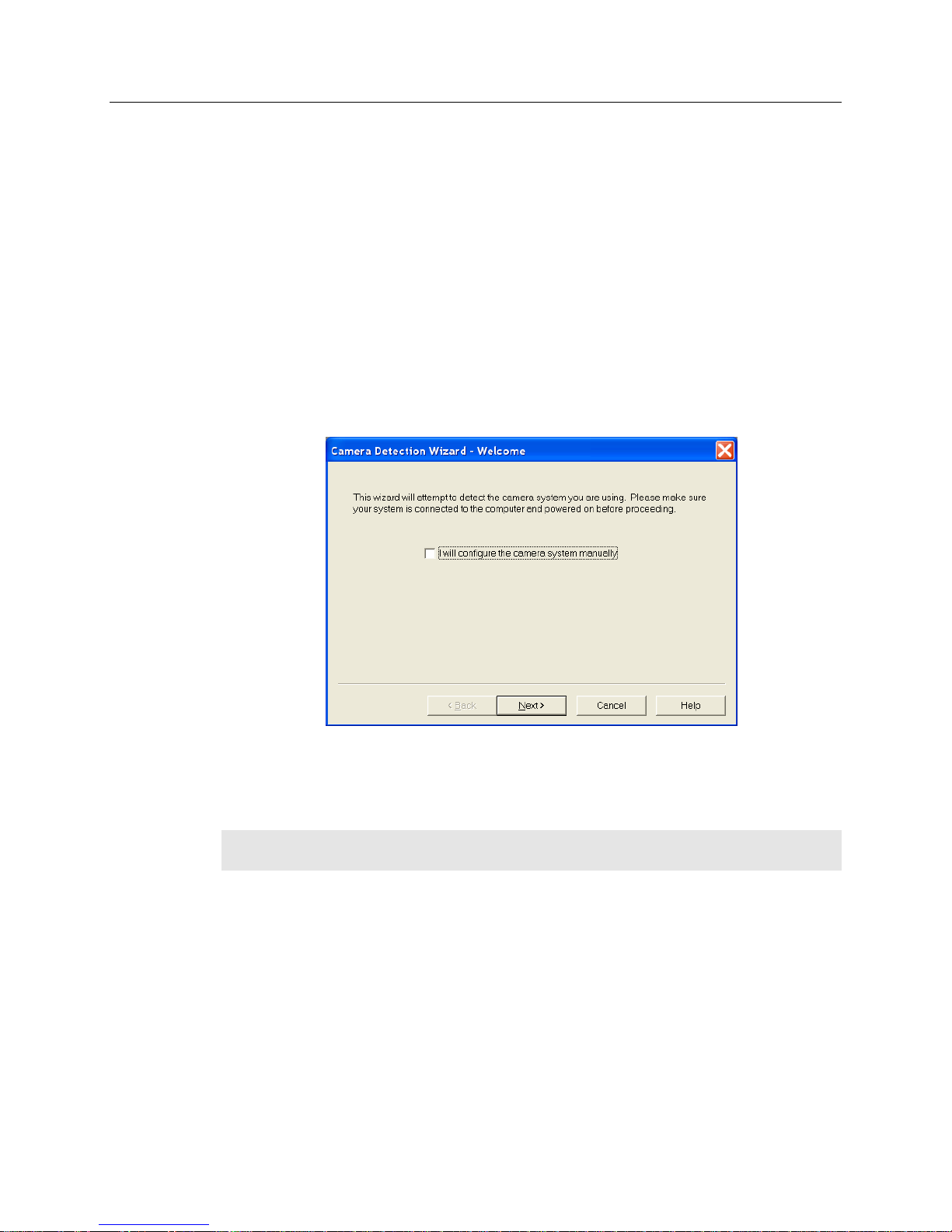
3. On the Welcome dialog (Figure 7), leave the checkbox unselected and click on
Next.
Figure 7. Camera Detection Wizard - Welcome dialog
4. Follow the instructions on the dialogs to perform the initial hardware setup: this
wizard enters default parameters on the Hardware Setup dialog tabs and gives
you an opportunity to acquire a test image to confirm the system is working.
Note: For a step-by-step procedure on basic system operation, refer to the "First Light"
section starting on page 30.
LightField
1. Make sure the PIXIS-XB is connected to the host computer and that the camera
power supply is turned on.
2. Start LightField.
3. While LightField is starting up, it will detect the available device(s) and load the
appropriate icons into the Available Devices area in the Experiment workspace.
4. When you drag an icon into the Experiment Devices area, the appropriate
expanders will be loaded into the Experiment Settings stack on the lefthand side
of the window.
Page 27

Chapter 4 System Setup 27
Figure 8. LightField Experiment Workspace
5. Because this is a new experiment, the default settings will automatically be
entered for the experiment device(s). These settings will allow you to begin
previewing (Run button) or acquiring (Acquire button) data.
Note: For a step-by-step procedure on basic system operation, refer to the "First Light"
section starting on page 32.
Page 28

28 PIXIS-XB System Manual Version 2
WARNING!
Caution
Connecting an External Shutter
Disconnecting or connecting the shutter cable to the camera while the camera is ON
can destroy the shutter or the shutter driver in the camera!
Introduction
While PIXIS-XB cameras do not have an internal shutter, there is provision for
connecting the following shutters to the Shutter connector on the rear of the specified
PIXIS-XB model:
PIXIS-XB:400 and 1024: UNIBLITZ VS25 (25 mm) external slit shutter.
PIXIS-XB:1300 and 2048: UNIBLITZ CS45 (45 mm) external slit shutter; and
UNIBLITZ XRS6, XRS14, and XRS25 X-ray shutters.
For the latest information on UNIBLITZ shutters by Vincent Associates, visit
www.uniblitz.com.
Electromechanical shutters typically have a lifetime of about a million cycles. Avoid
running the shutter unnecessarily. Also avoid using shorter exposure times and higher
repetition rates than are required.
External Shutter Cable Connection
1. Verify that the PIXIS-XB camera is turned OFF (i.e., the power supply is
switched OFF).
2. Connect the shutter cable from the external shutter (camera-dependent, see
Introduction, above) shutter to the LEMO® connector at the rear of the camera.
See page 76 for additional information.
3. Power the PIXIS-XB camera on.
Connecting/Disconnecting the PIXIS-XB USB Cable
As of November 1, 2005, you can hot plug the PIXIS-XB camera whenever the WinX
application is not running (i.e., connect or disconnect from the camera or the host computer
while the camera is powered ON). In the case of cameras built before November 1, 2005, you
must exit the WinX application and turn the camera power OFF before connecting the USB
cable to or disconnecting it from the camera or host computer.
Page 29

Chapter 5
Figure 9. Block Diagram of
PIXIS-XB System
Operation
Introduction
Once the PIXIS-XB camera has been installed as explained in
the preceding chapters, operation of the camera is
straightforward. In most applications you simply establish
optimum performance using the Focus mode (in
WinView/32, for example), set the target camera
temperature, wait until the temperature has stabilized, and
then do actual data acquisition in the Acquire mode.
Additional considerations regarding experiment setup and
equipment configuration are addressed in the software
manual.
During data acquisition, the CCD array is exposed to a
source and charge accumulates in the pixels. After the
defined exposure time, the accumulated signal is readout
of the array, digitized, and then transferred to the host
computer. Upon data transfer, the data are displayed
and/or stored via the application software. This sequence
is illustrated by the block diagram shown in Figure 9.
Whether or not the data are displayed and/or stored
depends on the data collection operation that has been
selected in the application software. In WinX and
LightField, the data collection operations use the
Experiment Setup parameters to establish the exposure
time (the period when signal of interest is allowed to accumulate on the CCD). Focus
{Preview} is more likely to be used in setting up the system (see the "First Light"
discussions) and Acquire is then used for the collection and storage of data. Briefly:
In Focus {Preview} mode, the number of frames is ignored. A single frame is
acquired and displayed, another frame is acquired and overwrites the currently
displayed data, and so on until Stop is selected. In WinX, the last frame acquired
before Stop is selected can be stored; in LightField, this frame cannot be stored.
Focus {Preview} mode is particularly convenient for familiarization and setting up.
For ease in focusing, the screen refresh rate should be as rapid as possible, achieved
by operating with axes and cross-sections off, and with Zoom 1:1 selected.
In Acquire mode, every frame of data collected can be automatically stored (the
completed dataset may include multiple frames with one or more accumulations).
This mode would ordinarily be selected during actual data collection. One limitation
of Acquire mode operation is that if data acquisition continues at too fast a rate for it
to be stored, data overflow may eventually occur. In WinX, this could only happen in
Fast Mode operation.
29
Page 30

30 PIXIS-XB System Manual Version 2
The remainder of this chapter is organized to first talk about the system on/off sequences.
Then "First Light" procedures for imaging and spectroscopy applications follow: these
procedures provide step-by-step instruction on how to initially verify system operation.
The last three sections discuss factors that affect exposure, readout, and digitization of the
incoming signal. By understanding these factors and making adjustments to software
settings you can maximize signal-to-noise ratio. For information about synchronizing
data acquisition with external devices, please refer to Chapter 6, Advanced Topics.
System On/Off Sequences
For WinView/32 and WinSpec/32, the following on/off sequences must be followed to
establish and maintain the communication link between the camera and the host computer:
1. The PIXIS-XB camera must be powered ON before the WinX application is
opened to ensure communication between the camera and the computer. If the
WinX application is opened and the PIXIS-XB is not powered ON, many of the
functions will be disabled and you will only be able to retrieve and examine
previously acquired and stored data. You must close the WinX application, power
the camera ON, and reopen the application before you can set up experiments and
acquire new data.
2. The WinX application must be closed before powering the camera OFF. If you
power the camera OFF before closing the application, the communication link with
the camera will be broken. You can operate the program in a playback mode (i.e.,
examine previously acquired data) but will be unable to acquire new data until you
have closed the application, powered the camera ON, and then reopened the
application.
WinX First Light Instructions
The following paragraphs provide step-by-step instructions for verifying the operation of
your PIXIS-XB system. The intent of this simple procedure is to help you gain basic
familiarity with the operation of your system and to show that it is functioning properly.
The procedure does not require an X-ray source. Once basic familiarity has been
established, then operation with other operating configurations, ones with more complex
timing modes, can be performed.
Once the PIXIS-XB system has been set up, operation of the camera is basically
straightforward. In most applications you simply establish optimum performance using the
Focus mode, select full frame, set the target camera temperature, and watch the dark charge
decrease as the CCD temperature approaches the set temperature.
Figure 10. Initial System Checkout Imaging Experiment Layout
Page 31

Chapter 5 Operation 31
Assumptions
The following procedure assumes that
1. You have already set up your system in accordance with the instructions in
Chapter 4 and are verifying the camera system operation.
2. You have read the previous sections of this chapter.
3. You are familiar with the application software.
4. The system is being operated in imaging mode.
Getting Started
1. If the system is liquid-cooled, double-check that the CoolCUBEII is filled with a
50:50 mixture of ethylene glycol and water and that the hose connections are
secure. Refer to “Making the Camera-Circulator Connections for a
CoolCUBEII” on page 25 for setup information. When satisfied that these
requirements are met, do the following.
a. Turn on the CoolCUBEII. It will power up and begin pumping coolant
through the camera.
b. Inspect the coolant hose connections to be sure there are no leaks.
2. Power ON the camera (the power switch is on the power supply).
Note: The camera must be turned on before WinX is opened, and WinX must be
closed before the camera is turned off.
3. Turn on the computer power and start the WinX application software.
Setting the Parameters
Note: The following procedure is based on WinView/32: you will need to modify it if
you are using a different application (for example, set up WinSpec/32 in imaging mode).
Basic familiarity with the WinX software is assumed. If this is not the case, you may
want to review the software manual or have it available while performing this procedure.
Set the software parameters as follows:
Environment dialog (Setup|Environment): Verify that the DMA Buffer size is
32 Mbytes (min.). Large arrays may require a larger buffer size. If you change
the buffer size, you will have to reboot the computer for this memory allocation
to be activated, and then restart WinView.
Controller|Camera tab (Setup|Hardware): Because the Camera Detection
wizard (Hardware Setup wizard for earlier software version) installed default
values appropriate for your system, verify the settings on this page.
Camera name: This information is read from the camera.
Controller type: This information is read from the camera.
Shutter type: None.
Readout mode: Select Full frame.
Page 32

32 PIXIS-XB System Manual Version 2
Detector Temperature (Setup|Detector Temperature…): Use the default
setting. When the array temperature reaches the set temperature, the Detector
Temperature dialog will report that the temperature is LOCKED. Note that
some overshoot may occur. This could cause temperature lock to be briefly lost
and then quickly re-established. If you are reading the actual temperature
reported by the application software, there may be a small difference between the
set and reported temperature when lock is established. This is normal and does
not indicate a system malfunction. Once lock is established, the temperature will
be stable to within ±0.05°C.
Note: The Detector Temperature dialog will not display temperature information
while you are acquiring data.
Cleans and Skips tab (Setup|Hardware): Click on Load Default Values and
click on Yes.
Experiment Setup Main tab (Acquisition|Experiment Setup…):
Exposure Time: 2 seconds
Accumulations & Number of Images: 1
Experiment Setup ROI tab (Acquisition|Experiment Setup…): Use this
function to define the region of interest (ROI).
* Imaging Mode: Select this mode if you are running WinSpec.
* Clicking on Full loads the full size of the chip into the edit boxes.
Experiment Setup Timing tab (Acquisition|Experiment Setup…):
* Timing Mode: Free Run
* Shutter Control: Normal
* Safe Mode vs. Fast Mode: Safe
Experiment Setup ADC tab (Acquisition|Experiment Setup…): Set the ADC
Rate to 2 MHz and verify CCD is not saturating at 2 seconds. If saturation is
occurring, further reduce ambient light. This will minimize smearing when
testing the performance of the camera without a shutter.
General tab (Display|Layout…): Select Horizontal and Vertical Cross Sections.
Confirming the Setup
If you are using a WinX application and the computer monitor for focusing, select Focus
from the Acquisition menu. Successive images will be sent to the monitor as quickly as
they are acquired. Since no X-ray source is being used, the acquired images will be of the
camera's dark charge. Signal changes may be more easily seen on the cross-section views.
Figure 11 shows the kind of image data you might see in WinView/32 (or in Image mode
for WinSpec/32). The horizontal and vertical cross sections have been turned on via the
General tab card (Display|Layout).
Page 33

Chapter 5 Operation 33
Figure 11. Example of WinView Data Acquired from First Light Procedure
Because the time to acquire and read out an image varies directly with the size of the
CCD, the observed frame rate will vary greatly depending on the CCD installed. With a
short exposure time, it is not uncommon for the frame readout time to be significantly
longer than the exposure time.
This completes First Light for WinX application software. If the system functioned as
described, you can be reasonably sure it has arrived in good working order. In addition,
you should have a basic understanding of how the system hardware is used.
LightField First Light Instructions
This section provides step-by-step instructions for acquiring an imaging measurement in
LightField for the first time. The intent of this procedure is to help you gain basic
familiarity with the operation of your system and to show that it is functioning properly.
Once basic familiarity has been established, then operation with other operating
configurations, ones with more complex timing modes, can be performed.
Assumptions
The following procedure assumes that
1. You have already set up your system in accordance with the instructions in the
previous chapters.
2. You have read the previous sections of this chapter.
3. You are familiar with the application software.
4. The system is being operated in imaging mode.
Page 34

34 PIXIS-XB System Manual Version 2
Getting Started
1. If the system is liquid-cooled, double-check that the CoolCUBEII is filled with a
50:50 mixture of ethylene glycol and water and that the hose connections are
secure. Refer to “Making the Camera-Circulator Connections for a
CoolCUBEII” on page 25 for setup information. When satisfied that these
requirements are met, do the following.
a. Turn on the CoolCUBEII. It will power up and begin pumping coolant
through the camera..
b. Inspect the coolant hose connections to be sure there are no leaks.
2. Power ON the camera (the power switch is on the power supply).
3. Turn on the computer power and start the LightField application software.
Setting the Parameters
Note: The following procedure is based on LightField. Basic familiarity with the
LightField software is assumed. If this is not the case, you may want to review the
software manual or have it available while performing this procedure.
1. After LightField opens, you should see an icon representing your camera in the
Available Devices area. In the figure above, the camera is a PIXIS-XB:1024BR.
2. Drag the icon into the Experiment Devices area.
Figure 12. Available Devices Area
Page 35

Chapter 5 Operation 35
Figure 13. Experiment Devices Area
3. Note that the Experiment Settings stack on the left now displays several
expanders. Because this is a new experiment, the default settings for the camera
will be active.
4. Open the Common Acquisition Settings expander and set the Exposure Time
to 100 ms.
5. The Status bar (at the bottom of the window) displays an icon for temperature
status. Temperature status reports the current temperature and whether the set
temperature has been reached. Clicking on the icon opens the Sensor expander
where the set temperature can be changed.
Confirming the Setup
1. Click on the View tab, just above Experiment Devices, to change to the display area.
Figure 14. View Area
Page 36

36 PIXIS-XB System Manual Version 2
2. Click on the Run button to start Preview mode. In this mode, images
will be continuously acquired and displayed. Since no X-ray source is being used,
the acquired images will be of the camera's dark charge.
Figure 15. View Area Displaying an Image
3. Now that you have confirmed that the camera is working, close LightField, and
power off the camera.
4. This completes First Light for WinX application software. If the system
functioned as described, you can be reasonably sure it has arrived in good
working order. In addition, you should have a basic understanding of how the
system hardware is used.
Exposure and Signal
Introduction
The following topics address factors that can affect the signal acquired on the CCD array.
These factors include array architecture, exposure time, CCD temperature, dark charge,
and saturation.
CCD Array Architecture
Charge coupled devices (CCDs) can be roughly thought of as a two-dimensional grid of
individual photodiodes (called pixels), each connected to its own charge storage “well.”
Each pixel senses the intensity of light falling on its collection area, and stores a
proportional amount of charge in its associated “well.” Once charge accumulates for the
specified exposure time (set in the software), the pixels are read out serially.
CCD arrays perform three essential functions: photons are transduced to electrons, integrated
and stored, and finally read out. CCDs are very compact and rugged and can withstand direct
exposure to relatively high light levels, magnetic fields, and RF radiation. They are easily
cooled and can be precisely thermostated to within a few tens of millidegrees.
Page 37

Chapter 5 Operation 37
As stated before, lowering the
temperature of the CCD will generally
enhance the quality of the acquired
signal. When WinX is the controlling
software, temperature control is done
via the Detector Temperature
dialog (see Figure 17) accessed from
the Setup menu. When LightField is
being used, temperature control is
done on the Sensor expander.
Figure 17. WinX
Detector Temperature dialog
Exposure Time
Exposure time (set on the Experiment Setup|Main tab {Common Acquisition
Settings expander}) is the time between start acquisition and stop acquisition commands
sent by the application software to the camera. In combination with triggers, these commands
control when continuous cleaning of the CCD stops and when the accumulated signal will be
readout. The continuous cleaning prevents buildup of dark current and unwanted signal
before the start of the exposure time. At the end of the exposure time, the CCD is readout and
cleaning starts again.
Because PIXIS-XB cameras do not incorporate an internal shutter, some signal may
accumulate on the array while it is being readout. This continuous exposure of the array
during readout may result in some smearing. However, exposures that are significantly
longer than the readout time can be performed without a shutter, as the amount of
smearing will be low.
If smearing or other factors require a shutter-like operation, the NOT SCAN {Not
Reading Out} or the SHUTTER {Shutter Open}signal at the LOGIC OUT connector
on the rear of the PIXIS-XB can be used to synchronize the x-ray source or an x-ray
shutter with the exposure-readout cycle so the CCD can be read out in darkness (see
"LOGIC OUT Control", on page 56 for more information). Figure 16 shows the action
of a mechanical shutter with respect to the NOT SCAN signal.
CCD Temperature
Once the target array temperature {Temperature Setpoint} has been set, the software
controls the camera's cooling circuits to reach set array temperature. On reaching that
temperature, the control loop locks to that temperature for stable and reproducible
performance. When temperature lock has been reached (temperature within 0.05°C of set
value), the current temperature is Locked. The on-screen indication allows easy
verification of temperature lock.
Figure 16. Mechanical Shutter Operation and NOT SCAN Signal
Page 38

38 PIXIS-XB System Manual Version 2
Caution
The time required to achieve lock can vary over a considerable range, depending on such
factors as the camera type, CCD array type, ambient temperature, etc. Once lock occurs,
it is okay to begin focusing. However, you should wait an additional twenty minutes
before taking quantitative data so that the system has time to achieve optimum thermal
stability.
The deepest operating temperature for a system depends on the CCD array size and
packaging. Refer to Table 4, on page 77, for typical deepest cooling temperatures.
Dark Charge
Dark charge (or dark current) is the thermally induced buildup of charge in the CCD over
time. The statistical noise associated with this charge is known as dark noise. Dark charge
values vary widely from one CCD array to another and are exponentially temperature
dependent. In the case of cameras with MPP type arrays, the average dark charge is
extremely small. Dark charge effect is more pronounced in the case of cameras having a
non-MPP array (such as deep-depletion devices).
With the light into the camera completely blocked, the CCD will collect a dark charge
pattern, dependent on the exposure time and camera temperature. The longer the
exposure time and the warmer the camera, the larger and less uniform this background
will appear. Thus, to minimize dark-charge effects, you should operate with the lowest
CCD temperature possible.
Note: Do not be concerned about either the DC level of this background. What you see
is not noise. It is a fully subtractable bias pattern. Simply acquire and save a dark charge
"background image" under conditions identical to those used to acquire the "actual"
image. Subtracting the background image from the actual image will significantly reduce
dark-charge effects.
If you observe a sudden change in the baseline signal, there may be excessive humidity in
the camera vacuum enclosure. Turn off the camera and contact Princeton Instruments
Customer Support. See page 92 for contact information.
Saturation
When signal levels in some part of the image are very high, charge generated in one pixel
may exceed the "well capacity" of the pixel, spilling over into adjacent pixels in a process
called "blooming." In this case a shorter exposure is advisable, with signal averaging to
enhance S/N (Signal-to-Noise ratio) accomplished through the software.
For signal levels low enough to be readout-noise limited, longer exposure times, and
therefore longer signal accumulation in the CCD, will improve the S/N ratio
approximately linearly with the length of exposure time. There is, however, a maximum
time limit for on-chip accumulation, determined by either the saturation of the CCD by
the signal or the loss of dynamic range due to the buildup of dark charge in the pixels.
Page 39

Chapter 5 Operation 39
Introduction
After the exposure time has
elapsed, the charge
accumulated in the array
pixels needs to be read out of
the array, converted from
electrons to digital format, and
transmitted to the application
software where it can be
displayed and/or stored.
Readout begins by moving
charge from the CCD image
area to the shift register. The
charge in the shift register
pixels, which typically have
twice the capacity of the
Figure 18. Array Terms for a CCD with a Dual Output
Amplifier
The upper left drawing in Figure 19
represents a CCD after exposure but
before the beginning of readout. The
capital letters represent different
amounts of charge, including both
signal and dark charge. This section
explains readout at full resolution,
where every pixel is digitized
separately.
Note: With PIXIS-XB cameras you
have a choice of amplifier (low noise
or high capacity). Depending on the
selected amplifier, the shift register
may be read out to the right or to the
left. For simplicity this drawing
shows the readout to the left.
Readout of the CCD begins with the
simultaneous shifting of all pixels
one row toward the "shift register,"
in this case the row on the top. The
shift register is a single line of pixels
along the edge of the CCD, not
sensitive to light and used for
Figure 19. Full Frame at Full Resolution
Readout
image pixels, is then shifted into the output node and then to the output amplifier where
the electrons are grouped as electrons/count. This result leaves the CCD and goes to the
preamplifier where gain is applied.
WinX and LightField allow you to specify the type of readout (full frame or binned), the
output amplifier, and the gain (the number of electrons required to generate an ADU).
Full Frame Readout
Page 40

40 PIXIS-XB System Manual Version 2
cR
ttt
exp
i x v
sr y x
R
t N t t N N t
readout only. Typically the shift register pixels hold twice as much charge as the pixels in
the imaging area of the CCD.
After the first row is moved into the shift register, the charge now in the shift register is
shifted toward the output node, located at one end of the shift register. As each value is
"emptied" into this node it is digitized. Only after all pixels in the first row are digitized is
the second row moved into the shift register. The order of shifting in our example is
therefore A1, B1, C1, D1, A2, B2, C2, D2, A3....
After charge is shifted out of each pixel the remaining charge is zero, meaning that the
array is immediately ready for the next exposure.
Below are the equations that determine the rate at which the CCD is read out.
The time needed to take a full frame at full resolution is:
(1)
where
tR is the CCD readout time,
t
is the exposure time, and
exp
tc is the shutter compensation time.
The readout time is approximately given by:
where
Nx is the smaller dimension of the CCD
Ny is the larger dimension of the CCD
tsr is the time needed to shift one pixel out of the shift register
tv is the time needed to digitize a pixel
ti is the time needed to shift one line into the shift register
A subsection of the CCD can be read out at full resolution, sometimes dramatically
increasing the readout rate while retaining the highest resolution in the region of interest
(ROI). To approximate the readout rate of an ROI, in Equation 2 substitute the x and y
dimensions of the ROI in place of the dimensions of the full CCD. Some overhead time,
however, is required to read out and discard the unwanted pixels.
(2)
Binning
Binning is the process of adding the data from adjacent pixels together to form a single
pixel (sometimes called a super pixel), and it can be accomplished in either hardware or
software. Rectangular groups of pixels of any size may be binned together, subject to
some hardware and software limitations.
Page 41

Chapter 5 Operation 41
Hardware binning is
performed on the CCD array
before the signal is read out of
the output amplifier. For
signal levels that are readout
noise limited this method
improves S/N ratio linearly
with the number of pixels
grouped together. For signals
large enough to render the
camera photon shot noise
limited, the S/N ratio
improvement is roughly
proportional to the squareroot of the number of pixels
binned.
Binning also reduces readout
time and the burden on
computer memory, but at the
expense of resolution. Since
shift register pixels typically
hold only twice as much
charge as image pixels, the
binning of large sections may
Figure 20. 2 × 2 Binning
ix
vsr
y
x
R
tN
n
t
n
t
NNt
2
Hardware Binning
result in saturation and “blooming,” or spilling of charge back into the image area.
Figure 20 shows an example of 2 2 binning. Each pixel of the image displayed by the
software represents 4 pixels of the CCD array. Rectangular bins of any size are possible.
Binning also reduces readout time and the burden on computer memory, but at the
expense of resolution. Since shift register pixels typically hold only twice as much charge
as image pixels, the binning of large sections may result in saturation and "blooming,” or
spilling of charge back into the image area.
The readout rate for n n binning is approximated using a more general version of the
full resolution equation. The modified equation is:
Software Binning
One limitation of hardware binning is that the shift register pixels and the output node are
typically only 2-3 times the size of imaging pixels. Consequently, if the total charge binned
together exceeds the capacity of the shift register or output node, the data will be corrupted.
(3)
Page 42

42 PIXIS-XB System Manual Version 2
This restriction strongly limits the number of pixels that may be binned in cases where there
is a small signal superimposed on a large background, such as signals with a large
fluorescence. Ideally, one would like to bin many pixels to increase the S/N ratio of the weak
peaks but this cannot be done because the fluorescence would quickly saturate the CCD.
The solution is to perform the binning in software. Limited hardware binning may be used
when reading out the CCD. Additional binning is accomplished in software, producing a
result that represents many more photons than was possible using hardware binning.
Software averaging can improve the S/N ratio by as much as the square-root of the
number of scans. Unfortunately, with a high number of scans (i.e., above 100) camera 1/f
noise may reduce the actual S/N ratio to slightly below this theoretical value. Also, if the
light source used is photon-flicker limited rather than photon shot-noise limited, this
theoretical signal improvement cannot be fully realized. Again, background subtraction
from the raw data is necessary.
This technique is also useful in high light level experiments, where the camera is again
photon shot-noise limited. Summing multiple pixels in software corresponds to collecting
more photons, and results in a better S/N ratio in the measurement.
Array Orientation
For square format CCDs (for example, 512 × 512B or 1024 × 1024F/B) you may orient
the CCD to achieve binning along either direction of the CCD.
Binning along columns provides maximum scan rate.
Binning along the rows minimizes crosstalk and is therefore better for multi-spectral
applications.
Figure 21. Binning and Array Orientation
Note: You can easily switch between these orientations by rotating the camera 90° and
changing the binning parameters in the application software.
Page 43

Chapter 5 Operation 43
Readout Port
{Quality}
Controller Gain {Analog Gain} Selection
1 {Low}
2 {Medium}
3 {High}
Low Noise
4 e-/count
2 e-/count
1 e-/count
High Capacity
16 e-/count
8 e-/count
4 e-/count
Output Amplifier {Quality} Selection
The output amplifier amplifies the collected charge from the output node and outputs it as
electrons/count. Although Figure 18 shows an array with two output nodes and amplifiers
(one set at each end of the shift register), some PIXIS-XB systems are available with a
single output node and amplifier. If your system has two output amplifiers, you can
choose the output amplifier to be used (High Capacity or Low Noise) via the
Acquisition|Experiment Setup…|ADC tab {Quality on the Analog to Digital
Conversion expander}:
High Capacity amplifier: Provides a spectrometric well capacity that is
approximately 3 times the well capacity for the Low Noise amplifier selection.
High Capacity is suitable when you have intense light signals or signals with
high dynamic range.
Low Noise amplifier: Provides the highest sensitivity performance and is
suitable when you have weak signals.
Note: The choice of output amplifier {Quality} and controller gain {Analog Gain} setting
should be considered together for the best signal capture. Examples of the interaction of
output amplifier and controller gain selections are shown in Table 2, page 43.
Controller Gain
Controller gain (a function of the preamplifier) is software-selectable and is used to
change the relationship between the number of electrons acquired on the CCD and the
Analog-to-Digital Units (ADUs or counts) generated. Selecting the amount of gain is
done on the Acquisition|Experiment Setup…|ADC tab {Analog to Digital
Conversion expander}. The choices are 1 {Low}, 2 {Medium}, and 3 {High}. Users
who measure high-level signals may wish to select Low to allow digitization of larger
signals. Medium is suitable for experiments within the mid-level intensity range. Users
who consistently measure low-level signals may wish to select High, which requires
fewer electrons to generate an ADU and reduces some sources of noise.
The "Certificate of Performance" supplied with the camera lists the measured gain values
at all settings.
Example: The following descriptions assume the Low Noise Readout Port has been
selected and that the actual incoming light level is identical in all three instances. The
numbers used illustrate the effect of changing a controller gain setting and may not
reflect actual performance: gain at the 1, 2, and 3 settings depends on the CCD
installed.
Table 2. Example of Controller Gain {Analog Gain} vs. Readout Port
Page 44

44 PIXIS-XB System Manual Version 2
1 {Low} requires four electrons to generate one ADU. Strong signals can be acquired
without flooding the CCD array. If the gain is set to Low and the images or spectra
appear weak, you may want to change the gain setting to Medium or High.
2 {Medium} requires two electrons to generate one ADU. If the gain is set to
Medium and the images or spectra do not appear to take up the full dynamic range of
the CCD array, you may want to change the gain setting to High. If the CCD array
appears to be flooded with light, you may want to change the setting to Low.
3 {High} requires one electron to generate one ADU and some noise sources are
reduced. Because fewer electrons are needed to generate an ADU, weaker signals can
be more readily detected. Lower noise further enhances the ability to acquire weak
signals. If the CCD array appears to be flooded with light, you may want to change
the setting to Medium or Low.
Digitization (Rate)
Introduction
After gain has been applied to the signal, the Analog-to-Digital Converter (ADC)
converts that analog information (continuous amplitudes) into a digital data (quantified,
discrete steps) that can be read, displayed, and stored by the application software. The
number of bits per pixel is based on both the hardware and the settings programmed into
the camera through the software (see "Readout,” page 39).
Factors associated with digitization include the digitization rate and baseline offset. The
speed at which digitization occurs is software-selectable but baseline offset is factory-set.
These factors are discussed in the following paragraphs.
Digitization Rate {Speed}
PIXIS-XB cameras incorporate dual digitization (100 kHz/2 MHz), which means that you
have a choice of how quickly the data will be digitized. Dual digitization provides
optimum signal-to-noise ratios at both readout speeds. Because the readout noise of CCD
arrays increases with the readout rate, it is sometimes necessary to trade off readout speed
for high dynamic range. The 2 MHz conversion speed is used for the fastest possible data
collection and the 100 kHz conversion speed is used where noise performance is the
paramount concern. Switching between the conversion speeds is completely under
software control for total experiment automation.
Note: In WinX, the ADC rate can be changed on the Experiment Setup|ADC tab. In
LightField, the speed is changed on the Analog-Digital Conversion expander.
Page 45

Chapter 5 Operation 45
ADC Offset (Bias)
With the camera completely blocked, the CCD will collect a dark charge pattern,
dependent on the exposure time and camera temperature. The longer the exposure time
and the warmer the camera, the larger this background will appear. To minimize the
amount of this signal that gets digitized, the baseline has been offset by adding a voltage
to the signal to bring the A/D output to a non-zero value, typically 500-600 counts. This
offset value ensures that all the true variation in the signal can really be seen and not lost
below the A/D “0” value. Since the offset is added to the signal, these counts only
minimally reduce the range of the signal from 65535 (16-bit A/D) to a value in the range
of 500-600 counts lower.
Note: It is important to note that the bias level is not noise. It is a fully subtractable
readout pattern. Every device has been thoroughly tested to ensure its compliance with
Princeton Instruments' demanding specifications.
Page 46

46 PIXIS-XB System Manual Version 2
This page intentionally left blank.
Page 47

Chapter 6
Advanced Topics
Introduction
Previous chapters have discussed setting up the hardware and the software for basic
operation. This chapter discusses topics associated with experiment synchronization.
Synchronization is set up on the Experiment Setup|Timing tab in WinX and on the
Trigger and Shutter expanders in LightField.
“Timing Modes,” the first topic, discusses Timing Modes {Trigger Response}, Shutter
Control {Shutter Mode}, and Edge Trigger. Also included under this topic is a discussion
of the EXT SYNC connector, the input connector for a trigger pulse.
“Fast and Safe Modes”, the second topic, discusses the Fast and the Safe modes. Fast is
used for real-time data acquisition. Safe is used in WinX when coordinating acquisition
with external devices or when the computer speed is not fast enough to keep pace with
the acquisition rate.
“Logic Out Control” discusses the EXT SYNC and LOGIC OUT output connectors on
the rear of the PIXIS-XB. The levels at this connector can be used to monitor camera
operation or synchronize external equipment.
“Kinetics Mode” describes how to set up and acquire data with the Kinetics Mode (a WinX
option, standard with LightField), which allows full-frame CCDs to take time-resolved
images/spectra. Note that full-frame CCDs require mechanical or optical masking of the
CCD array.
“Custom Modes,” the final topic, discusses Custom Chip {Custom Sensor} and Custom
Timing modes. These modes allow you to specify an active sub-area of the CCD array
and/or a faster vertical shift rate for the purpose of increased frame rate (pixels outside of
the area are not read). Custom Chip {Custom Sensor} mode requires mechanical or
optical masking of the array to prevent smearing.
47
Page 48

48 PIXIS-XB System Manual Version 2
Mode
Shutter Condition
Free Run {No Response}
Normal
External Sync {Readout Per Trigger}
Normal
External Sync{Readout Per Trigger}
PreOpen {Open Before Trigger}
External Sync {Readout Per Trigger} with Continuous
Cleans {Clean Until Trigger}
Normal
External Sync {Readout Per Trigger} with Continuous
Cleans {Clean Until Trigger}
PreOpen {Open Before Trigger}
Timing Modes
Overview
The basic PIXIS-XB timing modes are Free Run {No Response}, External Sync
{Readout Per Trigger}, and External Sync {Readout Per Trigger} with Continuous
Cleans {Clean Until Trigger}. These timing modes are combined with the Shutter options
to provide the widest variety of timing modes for precision experiment synchronization.
Table 3. Camera Timing Modes
Note: Since PIXIS-XB cameras do not use shutters, the Shutter Type selection on the
Hardware Setup|Controller/Camera tab should be "None".
The shutter options available include Normal, PreOpen {Open Before Trigger}, Disable
Opened {Always Open} or Disable Closed {Always Closed}. Disable simply means that
the shutter will not operate during the experiment. Disable closed {Always Closed} is
useful for making dark charge measurements. PreOpen {Open Before Trigger}, available
in the External Sync {Readout Per Trigger} and External Sync {Readout Per Trigger}
with Continuous Cleans {Clean Until Trigger} modes, opens the shutter as soon as the
PIXIS-XB is ready to receive an External Sync pulse. This is required if the time between
the External Sync pulse and the event is less than a few milliseconds, the time it takes the
shutter to open.
The shutter timing is shown in the timing diagrams that follow. Except for Free Run,
where the modes of shutter operation are identical, both Normal and PreOpen lines are
shown in the timing diagrams and flow chart.
The timing diagrams are labeled indicating the exposure time (t
), shutter compensation
exp
time (tc), and readout time (tR). Exposure time and readout are discussed in more detail in
Chapter 5. Note that if there is no shutter selected in the software, the shutter
compensation time (the time required to close a mechanical shutter) will be
approximately 0 ms.
Page 49

Chapter 6 Advanced Topics 49
Free Run {No Response}
In the Free Run {No Response} mode the
camera does not synchronize with the
experiment in any way. The shutter opens as
soon as the previous readout is complete, and
remains open for the exposure time, t
exp
. Any
External Sync signals are ignored. This mode
is useful for experiments with a constant light
source, such as a CW laser, an X-ray source,
or a DC lamp. Other experiments that can
utilize this mode are high repetition studies,
where the number of shots that occur during a
single shutter cycle is so large that it appears
to be continuous illumination.
Other experimental equipment can be
synchronized to the camera by using the
software-selectable output signal SHUTTER
{Normal} or NOT SCAN {Not Reading Out}
on the Hardware Setup|Controller Camera
tab {Trigger/Shutter expander} from the
LOGIC OUT connector. Shutter operation and
the NOT SCAN {Not Reading Out} output
signal are shown in Figure 23.
Figure 22. Free Run {No Response} Timing
Chart, part of the chart in Figure 30
External Sync {Readout Per Trigger}
In this mode all exposures are synchronized to an external source. As shown in the flow
chart, Figure 24, this mode can be used in combination with Normal or PreOpen {Open
Before Trigger} shutter operation. In Normal Shutter {Normal} mode, the camera waits
for an External Sync pulse and then opens the shutter for the programmed exposure
period. As soon as the exposure is complete, the shutter closes and the CCD array is read
out. The shutter requires up to 8 ms or more to open completely, depending on the shutter
model.
Figure 23. Free Run {No Response} Timing Diagram
Page 50

50 PIXIS-XB System Manual Version 2
External synchronization depends on an edge trigger (negative- or positive-going) which
must be supplied to the EXT SYNC connector on the back of the camera. The type of
edge must be identified in the application software to ensure that the shutter opening is
initiated by the correct edge (in WinX, this is done on the Experiment Setup|Timing
tab, in LightField on the Trigger/Shutter expander). Since the shutter requires up to
8 ms to fully open, the External Sync pulse provided by the experiment must precede the
actual signal by at least that much time. If not, the shutter will not be open for the
duration of the entire signal, or the signal may be missed completely.
Also, since the amount of time from initialization of the experiment to the first External
Sync pulse is not fixed, an accurate background subtraction may not be possible for the
first readout. In multiple-shot experiments this is easily overcome by simply discarding
the first frame.
In the PreOpen Shutter {Open Before Trigger} mode, on the other hand, shutter operation
is only partially synchronized to the experiment. As soon as the camera is ready to collect
data, the shutter opens. Upon arrival of the first External Sync pulse at the EXT SYNC
connector, the shutter remains open for the specified exposure period, closes, and the
CCD is read out. As soon as readout is complete, the shutter reopens and waits for the
next frame.
Figure 24. Chart Showing Two External Sync Timing Options
Page 51

Chapter 6 Advanced Topics 51
The PreOpen {Open Before Trigger} mode is useful in cases where an External Sync
pulse cannot be provided 8 ms (or the length of time a mechanical shutter takes to open)
before the actual signal occurs. Its main drawback is that the CCD is exposed to any
ambient light while the shutter is open between frames. If this ambient light is constant,
and the triggers occur at regular intervals, this background can also be subtracted,
providing that it does not saturate the CCD. As with the Normal Shutter {Normal} mode,
accurate background subtraction may not be possible for the first frame.
Also note that, in addition to signal from ambient light, dark charge accumulates during
the "wait" time (tw). Any variation in the external sync frequency also affects the amount
of dark charge, even if light is not falling on the CCD during this time.
Note: If EXT SYNC is still active (in Figure 25, this means that if it is still HIGH) at the
end of the readout, the hardware may interpret this as a second sync pulse, and so on.
Figure 25. Timing Diagram for External Sync Mode (+ edge trigger)
External Sync with Continuous Cleans {Clean Until Trigger} Timing
Another timing mode available with the PIXIS-XB is called Continuous Cleans {Clean
Until Trigger}. In addition to the standard "cleaning" of the array, which occurs after the
camera is enabled, this mode will remove any charge from the array until the moment the
External Sync pulse trigger edge is received.
Page 52

52 PIXIS-XB System Manual Version 2
Figure 26. Continuous Cleans {Clean Until Trigger} Flowchart
Once the External Sync pulse trigger edge is received, cleaning of the array stops as soon
as the current row is shifted, and frame collection begins: a delay time of up to one row
shift can be expected. With Normal Shutter {Normal} operation the shutter is opened for
the set exposure time. With PreOpen Shutter {Open Before Trigger} operation, the
shutter is open during the Continuous Cleaning {Clean Until Trigger}, and once the
External Sync pulse trigger edge is received the shutter remains open for the set exposure
time, then closes. If the vertical rows are shifted midway when the External Sync pulse
trigger edge arrives, the pulse is saved until the row shifting is completed, to prevent the
CCD from getting "out of step." As expected, the response latency is on the order of one
vertical shift time, from 1-30 µs depending on the array. This latency does not prevent the
incoming signal from being detected, since photo generated electrons are still collected
over the entire active area. However, if the signal arrival is coincident with the vertical
shifting, image smearing of up to one pixel is possible. The amount of smearing is a
function of the signal duration compared to the single vertical shift time.
Note: If EXT SYNC is still active (in Figure 27, this means that if it is still HIGH) at the
end of the readout, the hardware may interpret this as a second sync pulse, and so on.
Page 53

Chapter 6 Advanced Topics 53
Figure 29. Rear of PIXIS-XB Camera
Figure 27. WinX Continuous Cleans Timing Diagram
Figure 28. LightField Clean Until Trigger (CUT) Timing Diagram
EXT SYNC Trigger Input
The selected Timing Mode {Trigger
Response} determines how the camera will
respond to an External Sync pulse that is input
at the EXT SYNC connector on the rear of
the camera. Things to keep in mind when
setting up the External Sync pulse input are:
Pulse Height: 0 to +3.3V logic levels
(TTL-compatible).
Pulse Width (trigger edge frequency):
The time between trigger edges.
EXT SYNC Connector Impedance:
High impedance.
Trigger Edge {Polarity}: + (rising) or -
(falling) edge must be indicated on
the Experiment Setup|Timing tab
{Trigger/Shutter expander}.
Page 54

54 PIXIS-XB System Manual Version 2
Fast and Safe Modes
Introduction
The PIXIS-XB has been designed to allow the greatest possible flexibility when
synchronizing data collection with an experiment. The fundamental difference between
the Fast and Safe modes is how often the acquisition start and acquisition stop commands
are sent by the computer for a data collection sequence. With Safe Mode, the computer
sends a start and a stop command for each frame of a data sequence. With Fast Mode,
the computer sends only one start and one stop command for each data sequence. Once
the start command is sent, the selected timing mode and the shutter condition determine
when charge will be allowed to fall on the CCD array.
In WinX, the choice of Fast or the Safe data collection is made on the Experiment
Setup|Timing tab. The flowcharts in Figure 30 show the differences between the two
modes. In LightField, Fast data collection is always used.
Fast Mode (WinX and LightField)
In Fast operation, the PIXIS-XB runs according to the timing of the experiment, with no
interruptions from the computer. Fast operation is primarily for collecting "real-time"
sequences of experimental data, where timing is critical and events cannot be missed. Once
the PIXIS-XB is sent the start command by the computer, all frames are collected without
further intervention from the computer. The advantage of this timing mode is that timing is
controlled completely through hardware. A drawback to this mode is that the computer will
only display frames when it is not performing other tasks. Image display has a lower
priority, so the image on the screen may lag several images behind. A second drawback is
that a data overrun may occur if the number of images collected exceeds the amount of
allocated RAM or if the computer cannot keep up with the data rate.
Note: LightField always uses Fast Mode.
Safe Mode (WinX)
Safe Mode operation is useful when the camera is operated from a slower computer that
cannot process the incoming data fast enough. It is also useful when data collection must be
coordinated with external devices such as external shutters and filter wheels. As seen in
Figure 30, in Safe Mode operation, the computer controls when each frame is taken. After
each frame is received, the camera sends the Stop Acquisition command to the camera,
instructing it to stop acquisition. Once that frame is completely processed and displayed,
another Start Acquisition command is sent from the computer to the camera, allowing it to
take the next frame. Display is therefore, at most, only one frame behind the actual data
collection. One disadvantage of the Safe mode is that events may be missed during the
experiment, since the PIXIS-XB is disabled for a short time after each frame.
Note: When running WinX, Safe Mode must be used whenever the system is set up for
the optional Kinetics Mode. See “Kinetics Mode” (page 57) for more information about
this type of image acquisition and readout.
Page 55

Chapter 6 Advanced Topics 55
Figure 30. Chart of Safe and Fast Mode Operation
Page 56

56 PIXIS-XB System Manual Version 2
LOGIC OUT Control
The TTL-compatible logic level output (0 to +3.3 V) from the LOGIC OUT connector
on the rear panel can be used to monitor camera status and control external devices. By
default, the logic output level is high while the action is occurring. The timing of the
level changes depends on the output type selected on the Hardware
Setup|Controller/Camera tab {Trigger/Shutter expander}:
NOT SCAN {Not Reading Out}: It is at a logic low when CCD is being read;
otherwise high.
SHUTTER {Shutter Open}: Logic high when the shutter is open. The output
precisely brackets shutter-open time (exclusive of shutter compensation, tc) and
can be used to control an external shutter or to inhibit a pulser or timing
generator.
NOT READY {Busy}: After a start acquisition command, this output changes
state on completion of the array cleaning cycles that precede the first exposure.
Initially high, it goes low to mark the beginning of the first exposure. In free run
operation it remains low until the system is halted. If a specific number of frames
have been programmed, it remains low until all have been taken and then returns
high. Figure 31 assumes 3 frames have been programmed.
LOGIC 0 {Always Low}: The level at the connector is low.
LOGIC 1{Always High}: The level at the connector is high.
Figure 31. Comparison of NOT SCAN {Not Reading Out}, SHUTTER {Shutter Open}, and NOT
READY {Busy} Logic Output Levels
Page 57

Chapter 6 Advanced Topics 57
Kinetics Mode
Kinetics Mode is a purchased option for WinX applications. Kinetics Mode is
included in the standard LightField application.
Introduction
Kinetics mode uses the CCD to expose and store a limited number of images in rapid
succession. The time it takes to shift each line (or row) on the CCD is as short as a few
hundred nanoseconds to few microseconds, depending on the CCD. Therefore the time
between images can be as short as a few microseconds. Kinetics mode allows full
frame CCDs to take time-resolved images/spectra. Optical or mechanical masking of
the array is required.
Note: In WinX, if the Kinetics option has been installed in the PIXIS-XB, this readout
mode will be made available when you select the appropriate camera type on the
Hardware Setup dialog.
Below is a simplified illustration of kinetics mode. Returning to our 4 × 6 CCD example,
in this case 2/3 of the array is masked, either mechanically or optically and there is a
shutter (or other external device) controlling the exposure of the array to incoming
X-rays. The shutter opens to expose a 4 × 2 region. While the shutter remains open,
charge is quickly shifted just under the mask, and the exposure is repeated. After a third
image is collected the shutter is closed and the CCD is read out. Since the CCD can be
read out slowly, very high dynamic range is achieved. Shifting and readout are shown in
Figure 32.
Figure 32. Kinetics Readout
Page 58

58 PIXIS-XB System Manual Version 2
Figure 33. Hardware Setup dialog
Figure 34. Experiment Setup dialog
Figure 35. Readout expander:
Kinetics Readout Mode
Figure 36. Shutter and Trigger expanders
Kinetic Timing Modes
Kinetics mode operates with three timing modes: Free Run {No Response}, Single
Trigger {Readout Per Trigger}, and Multiple Trigger {Shift Per Trigger}. Free run {No
Response} mode is used for experiments that do not require any synchronization with the
experiments. The other two modes (single trigger and multiple trigger) require that an
external TTL pulse be applied to the camera via the EXT SYNC connector on the rear of
the camera.
Free Run (Non-Triggered Mode)
In the Free Run {No Response} Kinetics mode, the PIXIS-XB takes a series of images, each
with the Exposure time set through the software (in WinX, the exposure time is set on the
Experiment Setup|Main tab; in LightField on the Common Acquisition Settings
expander). The time between image frames, which may be as short as a few microseconds, is
limited by the time required to shift an image under the mask: this interimage time equals the
Vertical Shift rate (specified in ns/row) multiplied by the Window Size (the number of rows
allocated for an image frame). The exact number of frames depends on the selected Window
Size and is equal to the number of pixels perpendicular to the shift register divided by the
Page 59

Chapter 6 Advanced Topics 59
Window Size. Integrate signals (SHUTTER {Shutter Open}) or Readout signals (NOT
SCAN {Not Reading Out}) are provided at the LOGIC OUT connector for timing
measurements.
Example: Referring to the readout shown in Figure 32, there are 6 pixels perpendicular to
the shift register and the Window Size is 2 pixels high. The number of frames is 3. If the
Vertical Shift rate for the CCD is 1600 ns/row, the Shift time will be 3200 ns per frame.
Figure 37. Free Run Timing Diagram
Triggered Modes
In single trigger mode, the camera requires only one trigger to initiate an entire series of
“exposure-shift” cycles as shown in the timing diagram below. When Acquire or Focus
{Run} is clicked, the shutter (if there is an external X-ray shutter) is opened and the
camera uses the exposure time as entered in the software. The trigger is applied at the
Ext Sync connector on the rear of the PIXIS-XB. After the series is complete, the
shutter closes and the CCD is read out at normal speeds. Once the readout is complete,
the camera is ready for the next series of exposures. This timing is shown in Figure 38,
where a single External trigger pulse is used to collect a burst of 6 frames.
Figure 38. Single Trigger Timing Diagram
Page 60

60 PIXIS-XB System Manual Version 2
In multiple trigger mode, the shutter (if there is an external X-ray shutter) is opened when
Acquire or Focus {Run} is clicked and each “exposure-shift” cycle in the acquisition is
triggered independently by a pulse applied at the EXT SYNC connector. This mode is
useful when each subframe needs to be synchronized with a pulsed external light source
such as a laser. Once the series is complete, the shutter closes and readout begins. Since
the shutter is open during the entire series of images, irregularly spaced external pulses
will result in exposures of different lengths. Once the series has been read out the camera
is ready for the next series. This timing is shown in Figure 39, where a series of 6 frames
is collected with 6 External Sync pulses.
Custom Modes
Introduction
Custom Chip and Custom Timing modes are available as an option for WinX
applications; {Custom Sensor} and Custom Timing are standard (sensor and readout
mode-dependent) in LightField. These modes are intended to allow data acquisition at the
fastest possible rates for your camera. Custom Chip {Custom Sensor} allows you to
reduce the apparent size of the CCD array and Custom Timing allows you to select a
faster vertical shift time.
Custom Chip
Introduction
In addition to Binning and ROI (previously discussed in the manual), there is a third way
to reduce Readout Time – Custom Chip {Custom Sensor}. This feature allows you to
redefine the size of the CCD’s active area via software. Unlike setting a smaller region of
interest (ROI), which also involves reading out fewer pixels, this mode does not incur
overhead from discarding or skipping the rest of the rows. And, unlike both Binning and
ROI, Custom Chip {Custom Sensor} also relies on some form of array masking to ensure
that no light falls outside the currently set active area.
Figure 39. Multiple Trigger Timing Diagram
Note: Custom Chip is a WinX option. Custom Sensor is standard with LightField:
availability is sensor-dependent.
Page 61

Chapter 6 Advanced Topics 61
Princeton Instruments does not encourage users to change these parameter settings. For
most applications, the default settings will give the best results. We strongly advise
contacting the factory for guidance before customizing the chip definition.
In WinX, i, f Custom Chip has
been installed, selecting Show
Custom Chip check box on the
Controller/Camera tab adds the
Custom Chip tab to the
Hardware Setup dialog. The
Custom Chip parameters are shown
in Figure 40. The default values
conform to the physical layout of
the CCD array and are optimum for
most measurements.
In LightField, the Custom Sensor
pane (Figure 41) is accessed by
opening the Sensor expander and
clicking on the Custom Sensor
button.
By changing the values in the
Active fields, you can increase
image acquisition speed by reducing
the size of the active area in the
definition. The result will be faster
but lower resolution data
acquisition. Operating in this mode
would ordinarily require that the
chip be masked so that only the
reduced active area is exposed. This
will prevent unwanted charge from
spilling into the active area or being
transferred to the shift register.
By default, if there are no PreDummy rows, the serial register
Figure 40. WinX: Custom Chip tab
Figure 41. LightField: Custom Sensor pane
Software Settings
will be cleared before rows are shifted. If the Skip Serial Register Clean box is selected
when there are no Pre-Dummy rows, the register cleanout will be skipped and the chip
readout will be faster. This feature is not available for PVCAM-supported cameras.
Note: In LightField, the Clean Serial Register function only appears in the Sensor
Cleaning pane when the Inactive Area Top Margin has been set to 0 rows. Deselect the
check box to deactivate the serial register cleaning.
Page 62

62 PIXIS-XB System Manual Version 2
Figure 42. LightField: Custom Timing
Figure 43. WinX: Vertical Shift
Custom Timing
Notes:
1. This mode is standard with LightField for full frame CCD cameras.
2. This option is fully supported by WinX Version 2.5.18.1 (and higher).
In LightField, Custom Timing is accessed via the Custom Sensor button on the
Sensor expander. In the Custom Timing panel, you can select from among the listed
vertical shift rate choices (see Figure 42). Vertical shift rate is the time required to shift
one row into the serial register. The smaller the value, the faster charge will be shifted up
one row at a time toward the serial register. In WinX, if the Custom Timing option is
present and selected, the equivalent function is located on the Custom Timing tab on
the Hardware Setup dialog (see Figure 43).
Page 63

Chapter 7
Acquisition Started but Viewer Contents Do Not Update
Page 64
Baseline Signal Suddenly Changes
Page 64
Camera Stops Working
Page 64
Camera1 (or similar name) in Camera Name field
Page 65
Controller Is Not Responding
Page 66
CoolCUBEII: Low Coolant (Air in the Hoses)
Page 66
Cooling Troubleshooting
Page 67
Data Loss or Serial Violation
Page 68
Data Overrun Due to Hardware Conflict message
Page 68
Data Overrun Has Occurred message
Page 69
Device Is Not Found
Page 69
Device is Occupied
Page 70
Error Creating Controller message
Page 70
Overexposed or Smeared Images
Page 70
Program Error message
Page 71
Serial violations have occurred. Check interface cable.
Page 72
Shutter Failure
Page 72
Vignetting
Page 72
WARNING!
Troubleshooting
Do not attach or remove any cables while the camera system is powered on.
Introduction
The following issues have corresponding troubleshooting sections in this chapter.
63
Page 64

64 PIXIS-XB System Manual Version 2
Acquisition Started but Viewer Contents Do Not Update
In LightField, live data is normally displayed in the Experiment workspace viewer as it is
being acquired (Preview or Acquire mode). If the viewer is not being updated and
acquisition is occurring, check to see if there is a filename in the top row of the viewer: in
the figure below, the filename 2010 May 11 13_13_49.raw is displayed. If there is a
filename, click on the camera icon. The file data will be cleared from the viewer and the
live data will then be displayed.
Figure 44. Acquisition Display
Baseline Signal Suddenly Changes
A change in the baseline signal is normal if the temperature, gain, or speed setting has
been changed. If this occurs when none of these settings have been changed, there may
be excessive humidity in the camera vacuum enclosure. Turn off the camera and contact
Princeton Instruments Customer Support. See page 92 for contact information.
Camera Stops Working
Problems with the host computer system or software may have side effects that appear to
be hardware problems. If you are sure the problem is in the camera system hardware,
begin with these simple checks:
Turn off all AC power.
Verify that all cables are securely fastened.
Turn the system on.
If the system still does not respond, contact Princeton Instruments Customer Support.
Page 65

Chapter 7 Troubleshooting 65
Camera1 (or similar name) in Camera Name field
Figure 45. Camera1 in Camera Name Field
When the Camera Detection Wizard installs a new camera, the camera is automatically
named “Camera#” (where # = 1, 2 , or 3.., depending on the number of cameras detected)
This name will appear in the Hardware Setup title bar and as the active camera on the
Hardware Setup|Controller/Camera tab. If you would prefer a more specific name,
you can edit PVCAM.INI (located in the Windows directory) and rename the camera.
The new name will then be used by the system until the Camera Detection Wizard is run
again.
To change the default Camera Name:
1. Close WinView if it is running.
2. Using Notepad or a similar text editor, open PVCAM.INI from the Windows
directory (C:\WINDOWS, for example).
3. Edit the Name.
4. Save the edited file.
5. The next time you start WinView, the new name will be displayed on the
Hardware Setup dialog.
6. If you later re-run the Camera Detection Wizard, the name will be changed back
to the default name (i.e., Camera1).
Page 66

66 PIXIS-XB System Manual Version 2
WARNING!
Controller Is Not Responding
If this message pops up when you click on OK after selecting the "Interface Type" during
Hardware Setup (under the WinView Setup menu), the system has not been able to
communicate with the camera. Check to see if camera has been turned ON and if the
USB 2.0 interface card, its driver, and the USB cable have been installed.
If the camera is ON, the problem may be with the USB 2 card, its driver, or the
cable connections.
If the interface card is not installed, close WinView and turn the camera OFF.
Follow the interface card installation instructions provided with the interface
card, and cable the card to the USB 2 port on the rear of the camera. Then do a
"Custom" installation of WinView with the appropriate interface component
selected. Be sure to deselect the interface component that does not apply to your
system.
If the interface card is installed in the computer and is cabled to the USB 2 port
on the rear of the camera, close the application program and turn the camera
OFF. Check the cable connections.
If the interface card was installed after WinView was installed, close WinView
and do a "Custom" installation of WinView/32 with the appropriate interface
component selected. Be sure to deselect the interface component that does not
apply to your system.
CoolCUBEII: Low Coolant (Air in the Hoses)
If more than two inches (50.8 mm) of the coolant line is filled with air, the pump will
stop working and may be damaged. If flow stops while the pump is on, turn off the
CoolCUBE
1. Unscrew the reservoir cap (on top of the CoolCUBEII) and make sure that the coolant
reservoir contains coolant. If additional coolant is required, fill with a 50:50 mixture
of water and ethylene glycol.
2. Screw the reservoir cap back in.
3. Make sure the power switch is turned off before plugging the circulator in.
4. Plug the circulator into a 100-240 VAC, 47-63 Hz power source.
5. Turn the circulator on. Make sure there are no leaks or air bubbles in the hoses.
Note: Small bubbles (about the size of bubbles in soda) are common in the
CoolCUBEII especially at startup and do not prevent proper operation.
If there are no problems, continue to Step 6.
If there are leaks or air bubbles, turn the circulator off and correct the problem(s)
6. Turn the camera on.
7. Start WinView.
and add coolant.
II
by securing the hoses or adding more coolant to the reservoir. Turn the circulator
back on. Recheck and if there are no problems, continue to Step 6.
Page 67

Chapter 7 Troubleshooting 67
Cooling Troubleshooting
Temperature Lock Cannot be Achieved or Maintained.
Possible causes for not being able to achieve or maintain lock could include:
Ambient temperature greater than +23°C. This condition affects TE-cooled
cameras. If ambient is greater than +23°C, you will need to cool the camera
environment or raise the set temperature.
Airflow through the camera and/or circulator is obstructed. The camera needs to
have approximately two (2) inches (50 mm) clearance around the vented covers.
If there is an enclosure involved, the enclosure needs to have unrestricted flow to
an open environment. The camera vents its heat out the vents near the nose. The
air intake is near the rear of the camera.
A hose is kinked. Unkink the hose.
Coolant level is low. Add coolant. See “CoolCUBEII: Low Coolant
(Air in Hoses)” on page 66.
There may be air in the hoses. Add coolant. See “CoolCUBEII: Low
Coolant (Air in Hoses)” on page 66.
Circulator pump is not working. If you do not hear the pump running when the
CoolCUBEII is powered on, turn off the circulator and contact Customer Support.
The circulator is higher than the camera. Reposition the circulator so that it is
6 inches (150 mm) or more below the camera. The vertical distance should not
exceed 10 feet (3 m). Typically, the camera is at table height and the circulator is
on the floor.
The camera vacuum has deteriorated and needs to be refreshed. Contact
Customer Support.
The target array temperature is not appropriate for your particular camera and CCD
array.
The camera's internal temperature may be too high, such as might occur if the
operating environment is particularly warm or if you are attempting to operate at
a temperature colder than the specified limit. TE cameras are equipped with a
thermal-protection switch that shuts the cooler circuits down if the internal
temperature exceeds a preset limit. Typically, camera operation is restored
automatically in about ten minutes. Although the thermo-protection switch will
protect the camera, you are nevertheless advised to power down and correct the
operating conditions that caused the thermal-overload to occur.
Camera loses Temperature Lock
The internal temperature of the camera is too high. This might occur if the operating
environment is particularly warm or if you are trying to operate at a temperature colder
than the specified limit. If this happens, an internal thermal overload switch will disable
the cooler circuits to protect them. Typically, camera operation is restored in about ten
minutes. Although the thermal overload switch will protect the camera, users are advised
to power down and correct the operating conditions that caused the thermal overload to
occur.
Page 68

68 PIXIS-XB System Manual Version 2
Gradual Deterioration of Cooling Capability
While unlikely with the PIXIS-XB camera (guaranteed permanent vacuum for the life of
the camera), if you see a gradual deterioration of the cooling capability, there may be a
gradual deterioration of the camera’s vacuum. This can affect temperature performance
such that it may be impossible to achieve temperature lock at the lowest temperatures. In
the kind of applications for which cooled CCD cameras are so well suited, it is highly
desirable to maintain the system’s lowest temperature performance because lower
temperatures result in lower thermal noise and better the signal-to-noise ratio. Contact the
factory to make arrangements for returning the camera to the support facility.
Data Loss or Serial Violation
You may experience either or both of these conditions if the host computer has been set
up with Power Saving features enabled. This is particularly true for power saving with
regard to the hard drive. Make sure that Power Saving features are disabled while you are
running WinView.
Data Overrun Due to Hardware Conflict message
Figure 46. Data Overrun Due to Hardware Conflict dialog
If this dialog appears when you try to acquire a test image, acquire data, or run in focus
mode, check the CCD array size and then check the DMA buffer size. A large array (for
example, a 2048x2048 array), requires a larger DMA buffer larger setting than that for a
smaller array (for example, a 512x512 array).
To change the DMA buffer setting:
1. Note the array size (on the Setup|Hardware|Controller/CCD tab or the
Acquisition|Experiment Setup|Main tab Full Chip dimensions).
2. Open Setup|Environment|Environment dialog.
3. Increase the DMA buffer size to a minimum of 32 Mb (64 Mb if it is currently
32 Mb or 128 Mb if it is currently 64 Mb), click on OK, and close the WinX
application.
4. Reboot your computer.
5. Restart the WinX application and begin acquiring data or focusing. If you see
the message again, increase the DMA buffer size.
Page 69

Chapter 7 Troubleshooting 69
Data Overrun Has Occurred message
Because of memory constraints and the way that USB transfers data, a "Data overrun has
occurred" message may be displayed during data acquisition. If this message is displayed,
take one or more of the following actions:
1. Minimize the number of programs running in the background while you are
acquiring data with WinView.
2. Run data acquisition in Safe Mode.
3. Add memory.
4. Use binning.
5. Increase the exposure time.
6. Defragment the hard disk.
7. Update the USB2 driver.
If the problem persists, your application may be USB 2.0 bus limited. Since the host
computer controls the USB 2.0 bus, there may be situations where the host computer
interrupts the USB 2.0 port. In most cases, the interrupt will go unnoticed by the user.
However, there are some instances when the data overrun cannot be overcome because
USB 2.0 bus limitations combined with long data acquisition times and/or large data sets
increase the possibility of an interrupt while data is being acquired. If your experiment
requirements include long data acquisition times and/or large data sets, your application may
not be suitable for the USB 2.0 interface. If this is not the case and data overruns continue to
occur, contact Customer Support (see page 92 for contact information).
Device Is Not Found
When LightField is started, it looks for devices (cameras, spectrographs, and filters) that
are powered on and connected via a communications interface to the host computer. If it
cannot find a device that was used in the last experiment, it will continue to look for it.
Make sure the device is connected and powered on. If LightField cannot find a
spectrograph that is connected and powered on, turn the spectrograph off and
back on. LightField should now find it.
Figure 47. Devices Missing dialog
Page 70

70 PIXIS-XB System Manual Version 2
Figure 48. Occupied
Device icon
Cancel the load. Cancelling a load means that the last used experiment will not
be loaded automatically when LightField opens. However, you can load the
experiment after all the devices are available, you can start a new experiment
design, or you can load a different experiment that matches the devices you are
using.
Device is Occupied
Multiple instances of LightField can be running at the same time.
However, a device currently being used by one instance of LightField
will be shown in the Available Devices area as “Occupied” for all
other instances of LightField. To make a device available to the current
instance of LightField, either remove it from the Experiment Devices
area in the other instance or close the instance that is using the device.
Error Creating Controller message
Figure 49. Error Creating Controller dialog
This message may appear if the PVCAM.INI file has become corrupted or if the camera
was not turned on before you started WinView and began running the Camera Detection
Wizard. If one of these dialogs pops up:
1. See “Controller Is Not Responding,” page 66.
2. Run the Camera Detection Wizard.
Overexposed or Smeared Images
If an external shutter is being used, check to see that the shutter is opening and closing
correctly. Possible shutter problems include complete failure, in which the shutter no
longer operates at all: the shutter may stick or open (causing overexposed or smeared
images) or stick closed (resulting in no images). It may even happen that one leaf of the
shutter will break and no longer actuate. High repetition rates and short exposure times
will rapidly increase the number of shutter cycles and hasten the time when the shutter
will have to be replaced.
Page 71

Chapter 7 Troubleshooting 71
Program Error message
Figure 50. Program Error dialog
This dialog may appear if you have tried to acquire a test image, acquire data, or run in
focusing mode and the DMA buffer size is too small. A large array (for example, a
2048x2048 array), requires a larger setting than that for a smaller array (for example, a
512x512 array).
To correct the problem:
1. Click on OK.
2. Reboot the WinView.
3. Note the array size (on the Setup|Hardware|Controller/CCD tab or the
Acquisition|Experiment Setup|Main tab Full Chip dimensions). If your
camera contains a large array (such as a 2048x2048 array), and the DMA buffer
size is too small, there will not be enough space in memory for the data set.
4. Open Setup|Environment|Environment dialog.
5. Increase the DMA buffer size to a minimum of 32 Mb (64 Mb if it is currently
32 Mb or 128 Mb if it is currently 64 Mb), click on OK, and close WinView.
6. Reboot your computer.
7. Restart WinView and begin acquiring data or focusing. If you see the message
again, increase the DMA buffer size.
Page 72

72 PIXIS-XB System Manual Version 2
Serial violations have occurred. Check interface cable.
Figure 51. Serial Violations Have Occurred dialog
This error message dialog will appear if you try to acquire an image or focus the camera
and either (or both) of the following conditions exists:
The camera system is not turned ON.
There is no communication between the camera and the host computer.
To correct the problem:
1. Turn OFF the camera system (if it is not already OFF).
2. Make sure the computer interface cable is secured at both ends.
3. After making sure that the cable is connected, turn the camera system power ON.
4. Click OK on the error message dialog and retry acquiring an image or running in
focus mode.
Note: This error message will also be displayed if you turn the camera system OFF or a
cable comes loose while the WinX application software is running in Focus mode.
Shutter Failure
See "Overexposed or Smeared Images", page 70.
Vignetting
All CCD arrays have been tested for uniformity and do not exhibit any vignetting
(reduction of response) at the extreme ends of the array. If you do measure such reduction
in response across the array, it may be the result of one or more of the following
conditions:
Condensation of water on the edges of the array has occurred. This should not
The array is held with a special mask that has been designed to prevent damage
happen unless the cooling/pumping instructions, previously mentioned, were not
followed, if a leak is occurring at the interface between the ConFlat and chamber.
to the horizontal register.
Page 73

Declaration of Conformity
This section of the PIXIS-XB system manual contains the declaration of conformity for
PIXIS-XB systems.
73
Page 74

Page 75

Appendix A
Basic Specifications
Note: This appendix provides some of the basic specifications of a PIXIS-XB system. If
the information you are looking for is not here, it may be available in Appendix B,
"Outline Drawings" or on the appropriate data sheet. Data sheets can be downloaded
from the Princeton Instruments website (www.princetoninstruments.com).
CCD Arrays
e2v CCD47-10: 1024x1024BR, deep-depletion, 13 x 13 µm pixels
Princeton Instruments Exclusive: 1340x400BR, deep-depletion, 20 x 20 µm pixels
Princeton Instruments Exclusive: 1340x1300R/BR, deep-depletion, 20 x 20 µm pixels
Note: The arrays listed are those that were available at the time that the manual was written.
Contact Princeton Instruments or visit www.princetoninstruments.com for an updated list of
arrays supported by the PIXIS-XB.
Quantum Efficiency
75
Figure 52. PIXIS-XB Quantum Efficiency Curve
Page 76

76 PIXIS-XB System Manual Version 2
Pin 1: + VDC
Pin 2: Ground
Camera
Cooling: Thermoelectric (air) or circulating liquid (CoolCUBEII)
Gain: Software-selectable (high, medium, low)
Dimensions: See Appendix B.
Connectors:
EXT SYNC (MCX): 0 to +3.3 V logic level input to allow data acquisition to be
synchronized with external events. Trigger edge can be positive- or negative-
going as set in software. Synchronization and Timing Modes are discussed in
Chapter 6. MCX-to-BNC adapter cable supplied with system.
LOGIC OUT (MCX): 0 to +3.3 V logic level output for monitoring camera status.
Logic output is software-selectable as NOT SCAN, SHUTTER, NOT READY,
LOGIC 0, or LOGIC 1. Logic Out Control is discussed in Chapter 6. MCX-to-
BNC adapter cable supplied with system.
NOT SCAN {Not Reading Out}: Logic low when CCD is being read;
otherwise high.
SHUTTER {Shutter Open}: The output precisely brackets shutter-open
time (exclusive of shutter compensation) and can be used to control an
external shutter or to inhibit a pulser or timing generator.
NOT READY {Busy}: The output changes state on completion of the array
cleaning cycles that precede the first exposure. Initially high, it goes low to
mark the beginning of the first exposure. In free run operation, it remains low
until the system in halted. If a specific number of frames have been
programmed, it remains low until all have been taken, then returns high.
LOGIC 0 {Always Low) and LOGIC 1 {Always High}: Logic low and
logic high, respectively.
Shutter (2-pin LEMO): Active if there is no internal shutter. Used for connecting to
an external shutter. Customer must supply shutter cable.
UNIBLITZ® VS25: 25 mm shutter is supported for small array cameras
(PIXIS-XB:400 and PIXIS-XB:1024).
UNIBLITZ CS45: 45 mm shutter is supported for large array cameras
(PIXIS-XB:1300 and 2048).
The following X-ray shutters are ONLY supported for large array
cameras (PIXIS-XB:1300 and PIXIS-XB:2048): UNIBLITZ XRS6
(6 mm), XRS14 (14 mm) and XRS25 (25 mm).
For the latest information on UNIBLITZ shutters by Vincent Associates, visit
www.uniblitz.com.
USB 2.0 (USB B Female): Data link to computer via USB cable inserted at this
connector. Cable length of 5 meters is standard. Other lengths may be available.
Contact Customer Support for more information. USB A/B cable supplied with
system.
Page 77

Appendix A Basic Specifications 77
Pin 3, 5: 12 VDC
Pin 1, 2, 4: Return
Shell: Ground
Pin 1: 12 VDC
Pin 2: Ground
Pin 3: Chassis
CCD Size
Typical
1024x1024
-90°C
1340 x 400
-90°C
1340 x 1300
-65°C (air-cooled)
-70°C (CoolCUBEII)
2048 x 2048
-65°C (air-cooled)
-70°C (CoolCUBEII)
Power (DIN): 12 VDC (6.6A max) input from power supply for small array cameras
(PIXIS-XB:400 or PIXIS-XB: 1024).
Power (3-pin LEMO): 12 VDC (12.5A max) input from power supply for large
array cameras (PIXIS-XB:1300 or PIXIS-XB:2048).
Fan: (Air-cooled systems only) 24 CFM fan capacity at full power.
Coolant Ports: (Liquid-cooled systems only) Two interchangeable 1/4" CPC valved
quick disconnect fittings for connection to the CoolCUBEII circulator hoses.
Options
Deepest Operating Temperature (with ambient air at +20°C):
Table 4. Typical Deepest Operating Temperature
Temperature Stability: ±0.05°C; closed-loop stabilized-temperature control
Power Input: 100-240 VAC; 47 to 63 Hz, 1.9A. DC power to camera is provided by the
self-switching power supply.
Tripod Mount: 1/4-20 x .25" mounting hole at bottom of camera. M6 threaded adapter
supplied with system.
A/D Converters: Dual digitizers with 100 kHz/2 MHz readout rates. Software-
selectable. Low-speed operation gives better noise performance; high-speed
operation allows faster data acquisition.
Contact the factory for information regarding options available for your system.
Page 78

78 PIXIS-XB System Manual Version 2
This page intentionally left blank.
Page 79

Appendix B
Outline Drawings
Notes:
1. Dimensions are in inches [mm].
2. PIXIS-XB data sheets with the most up-to-date camera outline drawings can be
downloaded from the Princeton Instruments website (www.princetoninstruments.com).
PIXIS-XB Camera
79
Figure 53. PIXIS-XB:400 and 1024 (Air-Cooled)
Page 80

80 PIXIS-XB System Manual Version 2
Figure 54. PIXIS-XB:400 and 1024 (Liquid-Cooled)
Page 81

Appendix B Outline Drawings 81
Figure 55. PIXIS-XB:1300 and 2048 (Air-Cooled)
Page 82

82 PIXIS-XB System Manual Version 2
Figure 56. PIXIS-XB:1300 and 2048 (Liquid-Cooled)
Page 83

Appendix B Outline Drawings 83
Customer-Supplied Vacuum Interface Flange: Minimum Design
Requirements
Figure 57. Dimensional Drawing for Customer-Supplied Vacuum Interface Flange
Page 84

84 PIXIS-XB System Manual Version 2
CoolCUBEII Circulator
Figure 58. CoolCUBEII Circulator
Page 85

Appendix C
WinX
LightField
Active Rows Parallel to Shift Register
Active Height
Active Shift Register Columns
Active Width
ADC Rate
Speed
ADC Resolution
Bit Depth
Continuous Cleans
Clean Until Trigger
Controller Gain
Analog Gain
Custom Chip
Custom Sensor
Custom Timing
Vertical Shift Rate
Disable Pixel Bias Correction (PBC)
N/A
Disabled Closed (Shutter)
Always Closed (Shutter)
Disabled Open (Shutter)
Always Open (Shutter)
Easy Bin
Region of Interest expander functions
Edge Trigger
Trigger Determined By
External Sync
Readout Per Trigger
F.T. Dummies or Frame Transfer Dummies
Active Area: Top Margin
Focus
Preview
Free Run
No Response
Free Run (Kinetics)
No Response
Logic Out
Output Signal
Logic Out: Acquiring
Output Signal: Acquiring
Logic Out: Expose (Effective)
Output Signal: Effectively Exposing
Logic Out: Expose (Programmed)
Output Signal: Exposing
Logic Out: Image Shift
Output Signal: Shifting Under Mask
Logic Out: Logic 0
Output Signal: Always High (Inverted)
Cross-Referencing of WinX and
LightField Terms
WinX-to-LightField
85
Page 86

86 PIXIS-XB System Manual Version 2
WinX
LightField
Logic Out: Logic 1
Output Signal: Always High
Logic Out: Read Out
Output Signal: Reading Out
Logic Out: Shutter
Output Signal: Shutter Open
Logic Out: Wait for Trigger
Waiting For Trigger
Minimum Block Size
Final Section Height
Multiple Trigger (Kinetics)
Shift Per Trigger (Kinetics)
Normal Shutter
Normal (Shutter)
Number of Blocks
Final Section Count
Number of Cleans
Number of Clean Cycles
Number of Strips per Clean
Clean Cycle Height
Post-Dummy Rows Parallel to Shift Register
Active Area: Bottom Margin
Post-Dummy Shift Register Columns
Active Area: Right Margin
Pre-Dummy Rows Parallel to Shift Register
Active Area: Top Margin
Pre-Dummy Shift Register Columns
Active Area: Left Margin
PreOpen (Shutter)
Open Before Trigger (Shutter)
Readout Port
Quality
Shutter Close Compensation Time
Closing Delay
Shutter Control
Shutter Mode
Shutter Open Compensation Time
Opening Delay
Single Trigger (Kinetics)
Readout Per Trigger
Skip Serial Register Clean (deselected)
Clean Serial Register
Target Temperature
Temperature Setpoint
Timing Mode
Trigger Response
Vertical Shift
N/A
Vertical Shift (us/Row)
Storage Shift Rate
Window Size
Kinetics Window Height
Page 87

Appendix C Cross-Referencing of WinX and LightField Terms 87
LightField
WinX
Active Area: Bottom Margin
Post-Dummy Rows Parallel to Shift Register
Active Area: Left Margin
Pre-Dummy Shift Register Columns
Active Area: Right Margin
Post-Dummy Shift Register Columns
Active Area: Top Margin
F.T. Dummies or Frame Transfer Dummies
Active Area: Top Margin
Pre-Dummy Rows Parallel to Shift Register
Active Height
Active Rows Parallel to Shift Register
Active Width
Active Shift Register Columns
Always Closed (Shutter)
Disabled Closed (Shutter)
Always Open (Shutter)
Disabled Open (Shutter)
Analog Gain
Controller Gain
Bit Depth
ADC Resolution
Clean Cycle Height
Number of Strips per Clean
Clean Serial Register
Skip Serial Register Clean (deselected)
Clean Until Trigger
Continuous Cleans
Closing Delay
Shutter Close Compensation Time
Custom Sensor
Custom Chip
Final Section Count
Number of Blocks
Final Section Height
Minimum Block Size
Kinetics Window Height
Window Size
N/A
Disable Pixel Bias Correction (PBC)
N/A
Vertical Shift
No Response
Free Run
No Response (Kinetics)
Free Run (Kinetics)
Normal (Shutter)
Normal Shutter
Number of Clean Cycles
Number of Cleans
Open Before Trigger (Shutter)
PreOpen (Shutter)
Opening Delay
Shutter Open Compensation Time
Output Signal
Logic Out
Output Signal: Acquiring
Logic Out: Acquiring
Output Signal: Always High
Logic Out: Logic 1
Output Signal: Always High (Inverted)
Logic Out: Logic 0
LightField-to-WinX
Page 88

88 PIXIS-XB System Manual Version 2
LightField
WinX
Output Signal: Effectively Exposing
Logic Out: Expose (Effective)
Output Signal: Exposing
Logic Out: Expose (Programmed)
Output Signal: Reading Out
Logic Out: Read Out
Output Signal: Shifting Under Mask
Logic Out: Image Shift
Output Signal: Shutter Open
Logic Out: Shutter
Preview
Focus
Quality
Readout Port
Readout Per Trigger
External Sync
Readout Per Trigger (Kinetics)
Single Trigger (Kinetics)
Region of Interest expander functions
Easy Bin
Shift Per Trigger (Kinetics)
Multiple Trigger (Kinetics)
Shutter Mode
Shutter Control
Speed
ADC Rate
Storage Shift Rate
Vertical Shift (us/Row)
Temperature Setpoint
Target Temperature
Trigger Determined By
Edge Trigger
Trigger Response
Timing Mode
Vertical Shift Rate
Custom Timing
Waiting For Trigger
Logic Out: Wait for Trigger
Page 89

Warranty & Service
Limited Warranty
Princeton Instruments, a division of Roper Scientific, Inc. ("Princeton Instruments", "us",
"we", "our") makes the following limited warranties. These limited warranties extend to
the original purchaser ("You", "you") only and no other purchaser or transferee. We have
complete control over all warranties and may alter or terminate any or all warranties at
any time we deem necessary.
Basic Limited One (1) Year Warranty
Princeton Instruments warrants this product against substantial defects in materials and /
or workmanship for a period of up to one (1) year after shipment. During this period,
Princeton Instruments will repair the product or, at its sole option, repair or replace any
defective part without charge to you. You must deliver the entire product to the Princeton
Instruments factory or, at our option, to a factory-authorized service center. You are
responsible for the shipping costs to return the product. International customers should
contact their local Princeton Instruments authorized representative/distributor for repair
information and assistance, or visit our technical support page at
www.princetoninstruments.com.
Limited One (1) Year Warranty on Refurbished or Discontinued
Products
Princeton Instruments warrants, with the exception of the CCD imaging device (which
carries NO WARRANTIES EXPRESS OR IMPLIED), this product against defects in
materials or workmanship for a period of up to one (1) year after shipment. During this
period, Princeton Instruments will repair or replace, at its sole option, any defective parts,
without charge to you. You must deliver the entire product to the Princeton Instruments
factory or, at our option, a factory-authorized service center. You are responsible for the
shipping costs to return the product to Princeton Instruments. International customers
should contact their local Princeton Instruments representative/distributor for repair
information and assistance or visit our technical support page at
www.princetoninstruments.com.
XP Vacuum Chamber Limited Lifetime Warranty
Princeton Instruments warrants that the cooling performance of the system will meet our
specifications over the lifetime of an XP style detector (has all metal seals) or Princeton
Instruments will, at its sole option, repair or replace any vacuum chamber components
necessary to restore the cooling performance back to the original specifications at no cost
to the original purchaser. Any failure to "cool to spec" beyond our Basic (1) year limited
warranty from date of shipment, due to a non-vacuum-related component failure (e.g.,
any components that are electrical/electronic) is NOT covered and carries NO
WARRANTIES EXPRESSED OR IMPLIED. Responsibility for shipping charges is as
described above under our Basic Limited One (1) Year Warranty.
89
Page 90

90 PIXIS-XB System Manual Version 2
Sealed Chamber Integrity Limited 12 Month Warranty
Princeton Instruments warrants the sealed chamber integrity of all our products for a
period of twelve (12) months after shipment. If, at anytime within twelve (12) months
from the date of delivery, the detector should experience a sealed chamber failure, all
parts and labor needed to restore the chamber seal will be covered by us. Open chamber
products carry NO WARRANTY TO THE CCD IMAGING DEVICE, EXPRESSED OR
IMPLIED. Responsibility for shipping charges is as described above under our Basic
Limited One (1) Year Warranty.
Vacuum Integrity Limited 12 Month Warranty
Princeton Instruments warrants the vacuum integrity of “Non-XP” style detectors (do not
have all metal seals) for a period of up to twelve (12) months from the date of shipment.
We warrant that the detector head will maintain the factory-set operating temperature
without the requirement for customer pumping. Should the detector experience a Vacuum
Integrity failure at anytime within twelve (12) months from the date of delivery all parts
and labor needed to restore the vacuum integrity will be covered by us. Responsibility for
shipping charges is as described above under our Basic Limited One (1) Year Warranty.
Image Intensifier Detector Limited One Year Warranty
All image intensifier products are inherently susceptible to Phosphor and/or Photocathode
burn (physical damage) when exposed to high intensity light. Princeton Instruments
warrants, with the exception of image intensifier products that are found to have
Phosphor and/or Photocathode burn damage (which carry NO WARRANTIES
EXPRESSED OR IMPLIED), all image intensifier products for a period of one (1) year
after shipment. See additional Limited One (1) year Warranty terms and conditions
above, which apply to this warranty. Responsibility for shipping charges is as described
above under our Basic Limited One (1) Year Warranty.
X-Ray Detector Limited One Year Warranty
Princeton Instruments warrants, with the exception of CCD imaging device and fiber
optic assembly damage due to X-rays (which carry NO WARRANTIES EXPRESSED
OR IMPLIED), all X-ray products for one (1) year after shipment. See additional Basic
Limited One (1) year Warranty terms and conditions above, which apply to this
warranty. Responsibility for shipping charges is as described above under our Basic
Limited One (1) Year Warranty.
Software Limited Warranty
Princeton Instruments warrants all of our manufactured software discs to be free from
substantial defects in materials and / or workmanship under normal use for a period of
one (1) year from shipment. Princeton Instruments does not warrant that the function of
the software will meet your requirements or that operation will be uninterrupted or error
free. You assume responsibility for selecting the software to achieve your intended
results and for the use and results obtained from the software. In addition, during the one
(1) year limited warranty. The original purchaser is entitled to receive free version
upgrades. Version upgrades supplied free of charge will be in the form of a download
from the Internet. Those customers who do not have access to the Internet may obtain the
version upgrades on a CD-ROM from our factory for an incidental shipping and handling
charge. See Item 12 in the following section of this warranty ("Your Responsibility") for
more information.
Page 91

Warranty & Service 91
Owner's Manual and Troubleshooting
You should read the owner’s manual thoroughly before operating this product. In the
unlikely event that you should encounter difficulty operating this product, the owner’s
manual should be consulted before contacting the Princeton Instruments technical support
staff or authorized service representative for assistance. If you have consulted the owner's
manual and the problem still persists, please contact the Princeton Instruments technical
support staff or our authorized service representative. See Item 12 in the following section
of this warranty ("Your Responsibility") for more information.
Your Responsibility
The above Limited Warranties are subject to the following terms and conditions:
1. You must retain your bill of sale (invoice) and present it upon request for service
and repairs or provide other proof of purchase satisfactory to Princeton
Instruments.
2. You must notify the Princeton Instruments factory service center within (30)
days after you have taken delivery of a product or part that you believe to be
defective. With the exception of customers who claim a "technical issue" with the
operation of the product or part, all invoices must be paid in full in accordance
with the terms of sale. Failure to pay invoices when due may result in the
interruption and/or cancellation of your one (1) year limited warranty and/or any
other warranty, expressed or implied.
3. All warranty service must be made by the Princeton Instruments factory or, at our
option, an authorized service center.
4. Before products or parts can be returned for service you must contact the
Princeton Instruments factory and receive a return authorization number (RMA).
Products or parts returned for service without a return authorization evidenced by
an RMA will be sent back freight collect.
5. These warranties are effective only if purchased from the Princeton Instruments
factory or one of our authorized manufacturer's representatives or distributors.
6. Unless specified in the original purchase agreement, Princeton Instruments is not
responsible for installation, setup, or disassembly at the customer’s location.
7. Warranties extend only to defects in materials or workmanship as limited above
and do not extend to any product or part which:
has been lost or discarded by you;
has been damaged as a result of misuse, improper installation, faulty or
inadequate maintenance or failure to follow instructions furnished by us;
has had serial numbers removed, altered, defaced, or rendered illegible;
has been subjected to improper or unauthorized repair;
has been damaged due to fire, flood, radiation, or other "acts of God" or other
contingencies beyond the control of Princeton Instruments; or
is a shutter which is a normal wear item and as such carries a onetime only
replacement due to a failure with the original 1 year Manufacturer warranty.
8. After the warranty period has expired, you may contact the Princeton Instruments
factory or a Princeton Instruments-authorized representative for repair
information and/or extended warranty plans.
9. Physically damaged units or units that have been modified are not acceptable for
repair in or out of warranty and will be returned as received.
Page 92

92 PIXIS-XB System Manual Version 2
10. All warranties implied by state law or non-U.S. laws, including the implied
warranties of merchantability and fitness for a particular purpose, are expressly
limited to the duration of the limited warranties set forth above. With the exception
of any warranties implied by state law or non-U.S. laws, as hereby limited, the
forgoing warranty is exclusive and in lieu of all other warranties, guarantees,
agreements, and similar obligations of manufacturer or seller with respect to the
repair or replacement of any parts. In no event shall Princeton Instruments' liability
exceed the cost of the repair or replacement of the defective product or part.
11. This limited warranty gives you specific legal rights and you may also have other
rights that may vary from state to state and from country to country. Some states
and countries do not allow limitations on how long an implied warranty lasts,
when an action may be brought, or the exclusion or limitation of incidental or
consequential damages, so the above provisions may not apply to you.
12. When contacting us for technical support or service assistance, please refer to the
Princeton Instruments factory of purchase, contact your authorized Princeton
Instruments representative or reseller, or visit our technical support page at
www.princetoninstruments.com.
Contact Information
Roper Scientific's manufacturing facility for this product is located at the following
address:
Princeton Instruments
3660 Quakerbridge Road
Trenton, NJ 08619 (USA)
Tel: 800-874-9789 / 609-587-9797
Fax: 609-587-1970
Customer Support E-mail: techsupport@princetoninstruments.com
For immediate support in your area, please call the following locations directly:
North America 1-800- 899-1144 (toll free) or 1-609-587-9797
France +33 (1) 60 86 03 65
Germany +49 (0) 89 660 7793
Japan +81 (3) 5639 2741
UK & Ireland +44 (0) 1628 472 346
Singapore +65 6408 6240
China +86 10 659 16460
Otherwise, see our Support web page at www.princetoninstruments.com.
An up-to-date list of addresses and telephone numbers is posted on the
www.princetoninstruments.com/Support page. In addition, links on this
page to support topics allow you to send e-mail based requests to the
Customer Support group.
Page 93

Index
A
A/D converters ................................................... 44, 77
AC power requirements ........................................... 20
Acquisition started, viewer contents do not update . 64
ADC offset............................................................... 45
Air-circulation requirement ..................................... 13
Always High output level ........................................ 56
Always Low output level ......................................... 56
Analog gain .................................. See Controller gain
ANSI C library ........................................................ 15
B
Background DC level .............................................. 38
Background subtraction ........................................... 50
Baseline
offset ........................................................................... 45
signal .......................................................................... 38
troubleshooting .......................................................... 64
Baseline signal ......................................................... 38
Beryllium window, cleaning ...................................... 8
Binning
along columns ............................................................ 42
along rows .................................................................. 42
array orientation ......................................................... 42
computer memory burden ......................................... 41
hardware ..................................................................... 41
on-chip ....................................................................... 41
readout time ............................................................... 41
resolution loss ............................................................ 41
software ...................................................................... 41
effect on S/N ratio ................................................ 42
high light level measurements ............................. 42
shot-noise limited measurements ........................ 42
well capacity .............................................................. 42
Blooming ................................................................. 38
Busy output level ..................................................... 56
C
Cables
MCX to BNC adapter ............................................... 14
USB 2.0 ...................................................................... 14
Camera Detection wizard ............................ 26, 31, 65
Cautions
excessive humidity in CCD chamber....................... 38
CCD array
blooming ..................................................................... 38
dark charge effects ..................................................... 38
functions performed ................................................... 36
maximum on-chip integration ................................... 38
readout theory ............................................................ 39
shift register ................................................................ 39
signal-to-noise ratio vs on chip integration time ...... 38
square format .............................................................. 42
theory of operation ..................................................... 36
well capacity ............................................................... 38
Certificate of Performance ....................................... 14
Clean Until Trigger .................................................. 51
Cleaning
Beryllium window ....................................................... 8
camera........................................................................... 8
Compensation time .................................................. 48
Connectors
EXT SYNC ................................................................ 12
external shutter ..................................................... 12, 76
LEMO ......................................................................... 12
LOGIC OUT .............................................................. 12
power .................................................................... 12, 77
USB ...................................................................... 12, 76
Connectors LOGIC OUT ......................................... 76
Contact information ................................................. 92
Continuous Cleans ................................................... 51
Controller gain ......................................................... 43
Coolant mixture ....................................................... 16
CoolCUBEII
hose connections ........................................................ 25
Cooling .................................................................... 13
Cooling and vacuum ................................................ 68
Custom Chip option ................................ ........... 60, 61
Custom Sensor ................................................... 60, 61
Custom Timing ........................................................ 62
Customer support ..................................................... 92
D
Dark charge ............................................................. 51
definition of ................................................................ 38
dynamic range ............................................................ 38
pattern ......................................................................... 38
typical values .............................................................. 38
93
Page 94

94 PIXIS-XB System Manual Version 2
Dark current ............................................................. 38
Data loss .................................................................. 68
Data Overrun Due to Hardware Conflict message .. 68
Data Overrun Has Occurred message ...................... 69
Device is not found .................................................. 69
Device is Occupied .................................................. 70
Digitization rate ....................................................... 44
DMA buffer ....................................................... 68, 71
DMA buffer size ...................................................... 31
Dual A/D converters ................................................ 44
Dynamic range ......................................................... 38
E
Environmental conditions ........................................ 20
Environmental requirements .................................... 20
Error Creating Controller message .......................... 70
Exposure and Readout ............................................. 29
Exposure time .................................................... 37, 48
EXT SYNC connector ............................................. 12
pulse characteristics ................................................... 53
specifications ............................................................. 76
trigger input................................................................ 53
External Sync ................ See Also Readout Per Trigger
background subtraction ............................................. 50
dark charge accumulation ......................................... 51
EXT SYNC connector .............................................. 53
input pulse .................................................................. 49
pulse characteristics ................................................... 53
shutter synchronization ............................................. 50
timing ......................................................................... 49
timing mode ............................................................... 49
trigger input................................................................ 53
External synchronization See External Sync and EXT
SYNC connector
F
Fast mode................................................................. 54
data acquisition .......................................................... 54
flowchart .................................................................... 55
image update lag ........................................................ 54
Fiber optic extender kit ............................................ 16
First light ................................................................. 33
Freerun
experiments best suited for ....................................... 49
timing
diagram ................................................................. 49
flowchart ............................................................... 49
mode of data synchronization .............................. 49
Full frame readout ................................................... 39
I
Installation
PCI drivers............................................................ 22, 23
software ................................................................ 22, 23
Interface card
driver installation ................................................. 22, 23
K
Kinetics
multiple trigger ........................................................... 60
single trigger ............................................................... 59
L
LEMO connector ..................................................... 12
LightField ................................................................ 15
LOGIC 0 output level ........................................ 56, 76
LOGIC 1 output level ........................................ 56, 76
Logic Out levels
Always High .............................................................. 56
Always Low ............................................................... 56
Busy ............................................................................ 56
LOGIC 0 ............................................................... 56, 76
LOGIC 1 ............................................................... 56, 76
Not Reading Out ........................................................ 56
NOT READY ...................................................... 56, 76
NOT SCAN .......................................................... 56, 76
SHUTTER ............................................................ 56, 76
Shutter Open .............................................................. 56
Low noise amplifier ................................................. 43
M
Maintenance .............................................................. 8
MCX to BNC adapter cables ................................... 14
Memory allocation ................................................... 31
Multiple Trigger mode ............................................. 60
N
No Response
experiments best suited for ........................................ 49
timing
diagram .................................................................. 49
flowchart ................................................................ 49
mode of data synchronization .............................. 49
Not Reading Out ...................................................... 49
Not Reading Out output level .................................. 56
NOT READY output level ................................ 56, 76
NOT SCAN
output level ................................................................. 76
NOT SCAN output level ......................................... 56
H
Hardware binning .................................................... 41
Hardware Setup wizard ........................................... 31
High capacity amplifier ........................................... 43
Hose connections ..................................................... 25
O
Operating temperature ............................................. 77
Option
Custom Chip .............................................................. 60
Custom Timing .......................................................... 62
Page 95

Index 95
Output amplifier
dual ....................................................................... 39, 43
High Capacity ............................................................ 43
Low Noise .................................................................. 43
P
Performance certificate ............................................ 14
PICam ...................................................................... 15
Power cord ............................................................... 13
Power requirements ................................................. 20
Powerup procedure ............................................ 31, 34
Preopen Shutter mode .............................................. 50
Program Error message ........................................... 71
PVCAM.INI ............................................................ 65
R
Readout
binning ....................................................................... 40
hardware................................................................ 41
software ................................................................. 41
subsection of array..................................................... 40
time ............................................................................. 48
Readout Per Trigger ................ See also External Sync
Readout rate
control of .................................................................... 44
precision vs speed tradeoff ....................................... 44
Repairs ....................................................................... 9
Requirements
environmental ............................................................ 20
ventilation .................................................................. 13
Resolution, loss of with binning .............................. 41
S
S/N ratio............................................................. 38, 42
Safe mode
as used for setting up ................................................. 54
fast image update ....................................................... 54
flowchart .................................................................... 55
missed events ............................................................. 54
Safety related symbols used in manual ................... 10
Saturation ................................................................. 38
Serial violation ......................................................... 68
Serial Violations message ........................................ 72
Shift register ............................................................ 39
Shutter
external shutter connector ......................................... 12
lifetime ....................................................................... 28
modes
Disable .................................................................. 48
Normal .................................................................. 48
Preopen ........................................................... 48, 50
signs of failure ........................................................... 70
Shutter mode
Open Before Trigger ................................................. 51
PreOpen ..................................................................... 51
Shutter Open output level ........................................ 56
SHUTTER output level ..................................... 56, 76
Signal-to-noise ratio
on-chip integration ..................................................... 38
Single Trigger mode ................................................ 59
Software binning...................................................... 42
Specifications
operating temperature ................................................ 77
PIXIS-XB ................................................................... 76
System power up ............................................... 31, 34
T
Technical support .................................................... 92
Temperature
control problems ........................................................ 67
operating ..................................................................... 77
specifications .............................................................. 77
thermal cutout switch................................................. 67
Temperature control ................................................ 37
effect of vacuum deterioration .................................. 68
Temperature lock ..................................................... 37
Thermal cutout switch ............................................. 67
Timing control ......................................................... 54
Timing modes .......................................................... 48
Trigger modes
multiple trigger (Kinetics) ......................................... 60
single trigger (Kinetics) ............................................. 59
Troubleshooting
acquisition start but viewer contents do not update . 64
baseline change .......................................................... 64
camera stops working ................................................ 64
Camera1 in Camera Name field ............................... 65
controller not responding........................................... 66
CoolCUBEII
air in hoses ............................................................. 66
low coolant ............................................................ 66
data loss ...................................................................... 68
data overrun (hardware conflict) ............................... 68
data overrun message ................................................ 69
Device is not found message ..................................... 69
Device is Occupied .................................................... 70
DMA buffer size .................................................. 68, 71
Error Creating Controller message ........................... 70
program error ............................................................. 71
serial violation ............................................................ 68
Serial Violations message ......................................... 72
shutter failure........................................................ 70, 72
temperature lock ........................................................ 68
vacuum deterioration ................................................. 68
vignetting .................................................................... 72
U
USB 2.0
cable ............................................................................ 14
data overrun ................................................................ 69
Page 96

96 PIXIS-XB System Manual Version 2
V
Vacuum deterioration .............................................. 68
Ventilation requirements ......................................... 13
Vertical shift rate ..................................................... 62
Vignetting ................................................................ 72
W
Warnings
cleaning .........................................................................8
protective grounding ....................................................7
replacement powercord ................................................8
touching the CCD array ...............................................8
Warranties
image intensifier detector .......................................... 90
one year ...................................................................... 89
one year on refurbished/discontinued products ....... 89
Warranties (cont.)
owner's manual and troubleshooting ........................ 91
sealed chamber ........................................................... 90
software ...................................................................... 90
vacuum integrity ........................................................ 90
XP vacuum chamber ................................................. 89
x-ray detector ............................................................. 90
your responsibility ..................................................... 91
Website .................................................................... 92
Well capacity ........................................................... 38
blooming ..................................................................... 38
restrictions on hardware binning ............................... 42
saturation .................................................................... 38
Wizard
Camera Detection ......................................... 26, 31, 65
Hardware Setup.......................................................... 31
 Loading...