

Page 1

PI-MAX2 DIF Camera
Introduction
This technical note assumes a basic understanding of the operation of the PI-MAX2 and
PTG in Gate Mode using WinView or WinSpec. Please refer to Chapter 7 of the
PI-MAX/PI-MAX2 system manual if you do not feel confident with the basic operation
of the PI-MAX and PTG in Gate mode.
The purpose of the PI-MAX2 DIF system is to acquire a pair of gated images in rapid
succession. The time between frames can be as short as 2 µs with exposure times as short
as 5 ns. The DIF capability is ideally suited to capturing rapidly evolving events. These
experiments will fall into one of two broadly applicable categories: single trigger and
dual trigger experiments. Single trigger experiments involve a single impulse event that
evolves over time such as a laser-induced plasma or luminescence decay. Dual trigger
experiments involve two impulses separated in time such as double laser pulse
velocimetry measurements.
Requirements
The following requirements must be met for DIF operation:
(Dual Image Feature)
•
the PI-MAX2 must use an interline CCD,
•
the controller must have a High Speed PCI Interface (TAXI) board and a PTG
board installed, and
•
the entire system must be set up for DIF operation at the factory.
In addition to these requirements, it is recommended that the intensifier have a fast decay
phosphor (P46 or P47). Since DIF operation involves acquiring images in rapid
succession, phosphor persistence can become the limiting factor in the rate of image
acquisition.
WinView or WinSpec software (version 2.5.16 or later) can control the DIF functionality
of the PI-MAX2 and provides full access to the two DIF timing modes: single trigger and
dual trigger.
Interline CCD Operation
An interline CCD consists of alternating columns of light sensitive pixels and storage pixels.
The light sensitive columns are referred to as the active area and acquire the image. The
storage pixels are called the masked area and store the image in the dark while it is read out.
With this architecture, the CCD can acquire a second image while the first image is being
read out, unlike a standard CCD, which must read out the first image before the second
acquisition can begin. The ability of the interline CCD to quickly transfer an image under the
masked columns and hold it there makes DIF possible. As soon as the first image is acquired,
Princeton Instruments 1 of 8 May 26, 2004
E:\Manuals\Sy stems\PI-MAX\PI -MAX2 DIF C amera.do c
Page 2
PI-MAX2 DIF Camera
it is shifted under the masked area and held. The second exposure begins and is held in the
active area until the first image is read out.
Timing Modes
In WinView and WinSpec, the timing modes available in the
Setup…|Timing
tab are different from those in standard intensified systems. The
Acquisition|Experiment
available timing modes are:
Single Trig. Mode: two shot, one trigger for both shots.
Dual Trig. Mode: two shot, each shot requires a trigger.
The trigger(s) can be generated by an external source attached to the PTG or the PTG can
generate the trigger(s) internally. When using a PTG internal trigger, the experiment will
normally be triggered by a signal from the ST-133. Typically, the rising edge of T0, from
the PTG, is used.
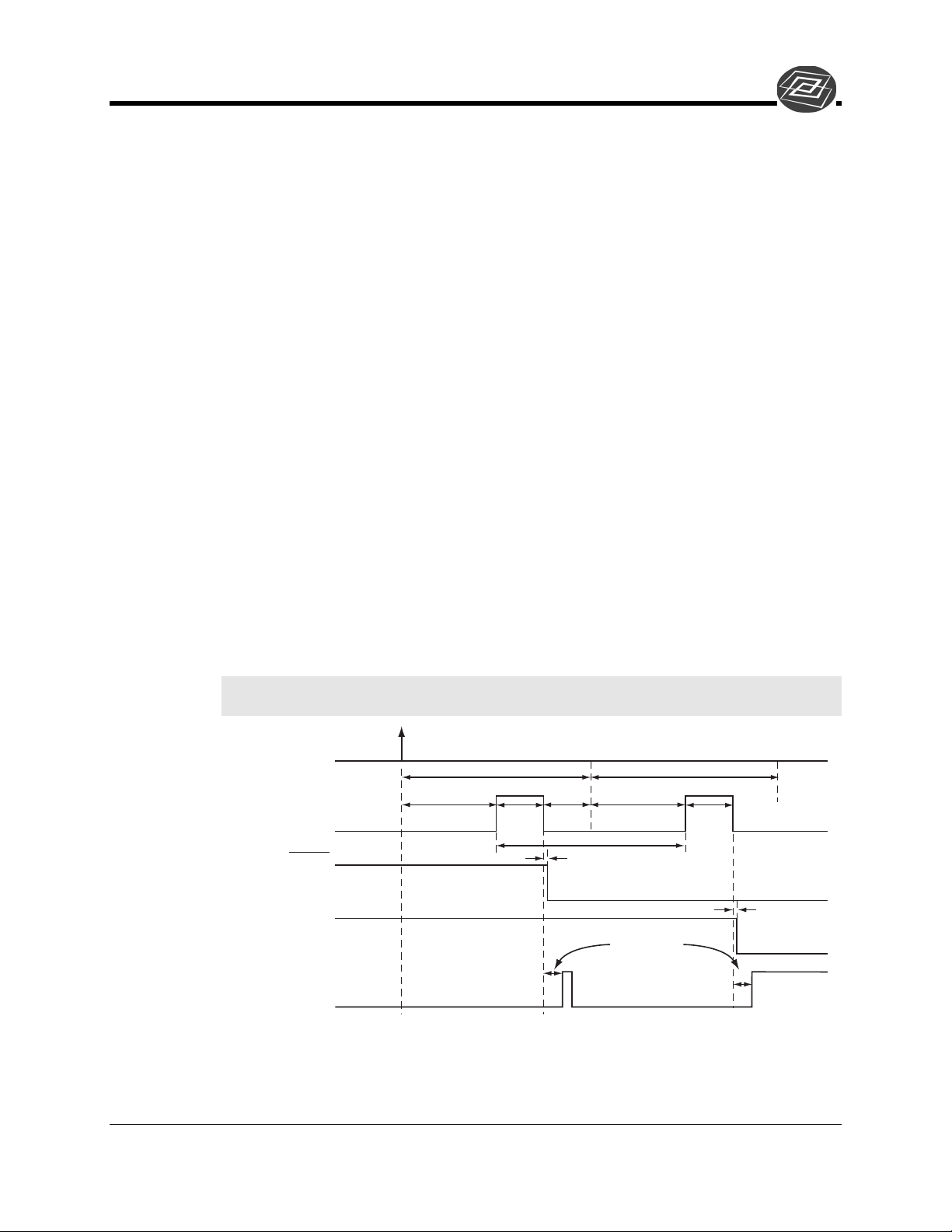
Single Trigger Mode
The Single Trigger Mode only requires a single trigger to initiate the acquisition of both
images of the DIF operation. The Single Trigger Mode uses the Burst Mode feature of
the PTG to acquire two images from a single trigger event. On the
Gating
Pulse dialog, the Burst Mode should be turned on. The Number of Pulses must be set to
2, and the time between the images is set by the Burst Period. It is very important that the
Burst Period be large enough to accommodate the gate width, gate delay, and phosphor
decay time. To set the gate width and delay, select Repetitive Mode from the
of the Pulse dialog and then click on the Setup button.
Note: Sequential Mode will not create different gate width and delay for the two images
in Single Trigger Mode due to Burst Mode selection.
tab of the
Gating
tab
Trigger
Burst Period Burst Period
Intensifier Gate
SCAN
Shutter
CCD Operation
Gate
Delay
Burst Period ≥ Gate Delay + Gate Width + Shutter Comp.
Shutter Comp. = Phosphor Decay Time
Gate
Width
≥ Shutter
Comp.
400 ns
≥ 2 µs
Shutter Comp.
Shift
first image
Gate
Delay
Gate
Width
400 ns
Read out
both images
Figure 1. DIF Operation: Single Trigger Timing Diagram
May 26, 2004 2 of 8 Princeton Instruments
E:\Manuals\Sy stems\PI-MAX\PI -MAX2 DIF C amera.do c
Page 3
PI-MAX2 DIF Camera
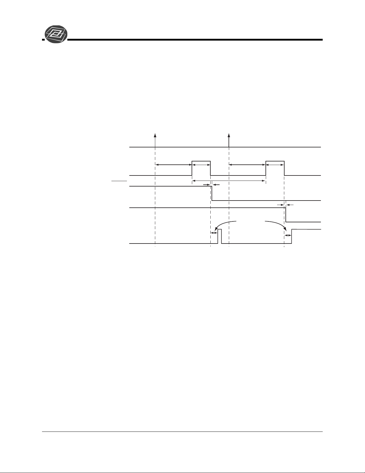
Dual Trigger Mode
The Dual Trigger Mode requires two triggers to acquire both images of the DIF operation.
The PTG will control the gating of the intensifier for both images. To make the gate width
and delay the same for both images, select Repetitive Mode from the
Pulser dialog then click the Setup button to set the values. To make the gate width and delay
different for each pulse, select Sequential Mode from the
then click the Setup button to set the values. The Number of Images should be set to 2, and
the first image will use the starting values for gate width and delay while the second image
will use the ending values.
Trigger
Gating
Gating
tab of the Pulse dialog,
tab of the
Intensifier Gate
SCAN
Shutter
CCD Operation
Gate
Delay
Gate
Width
400 ns
Shift
first image
Shutter Comp. = Phosphor Decay Time
Gate
Delay
≥ 2 µs
Shutter Comp.
Gate
Width
Figure 2. DIF Operation: Dual Trigger Timing Diagram
400 ns
Read out
both images
Princeton Instruments 3 of 8 May 26, 2004
E:\Manuals\Sy stems\PI-MAX\PI -MAX2 DIF C amera.do c
Page 4

PI-MAX2 DIF Camera
Setup
Hardware
Trig IN
PTG
EXT. TRIG. IN
PRE. TRIG. IN
T0
TIMING GEN.
6050-0406
ST-133 Controller
Camera
Camera
Pwr
Signal
6050-0499
Serial Com
6050-0148-CE
Computer
AUX. TRIG. OUT
TRIG.
*
In current systems, the Timing Gen. cable can remain connected
during Shutter Mode operation. Older systems may require that it be
disconnected.
**
Spectrograph connection is optional.
*
Timing
Gen
PI-MAX2
Power
Signal
Spectrograph
Acton 300i**
110/220
6050-0492
6050-0493
Figure 3. System Diagram: DIF Operation
110/220
110/220
GPIB
Operation
Software
For the purposes of this setup, it is assumed that you are using either WinView or
WinSpec to control the system.
The operation of the PI-MAX2 in DIF mode is similar to the standard operation of a
PI-MAX2 with PTG. There are only a few differences due to the special timing modes of
DIF, and they will be outlined here. Because there are two timing modes in DIF
operation, there are two procedures for setting up the experiment.
Single Trigger Mode
1. The first requirement is that the PI-MAX2 camera be aligned and focused on the
area of interest in the experiment. This is best accomplished while the PI-MAX2
is operating in Interline mode (i.e., before switching to DIF mode). The
procedure for initial focus is outlined in Chapter 4: First Light of the PI-MAX/PIMAX2 system manual.
2. After the alignment and focus, the PI-MAX2 system needs to be put into DIF
Setup
mode. Select Hardware from the
Under Readout Mode, select DIF and then click
menu to open the Hardware dialog.
OK
.
May 26, 2004 4 of 8 Princeton Instruments
E:\Manuals\Sy stems\PI-MAX\PI -MAX2 DIF C amera.do c
Page 5

PI-MAX2 DIF Camera
3. The PI-MAX2 must be set to Gate mode for the intensifier to operate properly.
Either click on the
mode on the
Gate mode
Acquisition|Experiment Setup…|Main
button on the Custom Toolbar or select Gate
tab.
4. Now the PTG needs to be programmed to match the experiment. On the
menu, select Pulser and click on Pulser Setup (or click the
Pulser Setup
Setup
button in the Custom Toolbar).
a. In the Pulser dialog, select the
Trigger
tab. The PTG can be triggered by an
external trigger signal such as a TTL (typical settings for a TTL trigger might
be: 1.7 V, positive edge, DC, 50 Ohm) or a photodiode (typical settings for a
photodiode might be: 8.0 V, positive edge, DC, high Z), or the PTG can use
its own internal clock to trigger the experiment. Select the appropriate one
for your experiment. In either case, the trigger frequency should be slow
enough so that the period between triggers is longer than the entire DIF
experiment. For example, if the Burst Period is 6 µs, then the trigger
frequency should be 8333 Hz [1 / (2 * 6 µs)].
b. Now select the
Gating
tab. In the Burst Mode section, turn Burst Mode on.
Set the Number of Pulses to 2. The Burst Period must be set to a value that is
greater than Gate Width + Gate Delay + Phosphor Decay. Ensure that the
Setup
Gating is set to Repetitive, and then click on the
button to set the
appropriate gate width and delay.
OK
c. At the bottom of the Pulser Setup dialog, click
to download the gating
sequence to the PTG.
5. The CCD parameters need to be set to the appropriate values for DIF operation.
Select Experiment Setup from the
Acquisition
menu.
a. In the
b. In the
Timing
Main
tab, select Single Trig. Mode.
tab, verify that the Number of Images is 2 and the Intensifier is
in Gate Mode.
c. When the experiment is ready, click the
Acquire
button to start the image
acquisition.
Dual Trigger Mode
1. As with Single Trigger Mode, the PI-MAX2 camera must first be aligned and
focused on the area of interest in the experiment. This is best accomplished while
the PI-MAX2 is operating in Interline mode (i.e., before switching to DIF mode).
The procedure for initial focus is outlined in Chapter 4: First Light of the
PI-MAX/PI-MAX2 system manual.
2. The PI-MAX2 system needs to be put into DIF mode. In the
Setup
the Hardware dialog. Under Readout Mode, select DIF and then click
3. The PI-MAX2 must be set to Gate mode for the intensifier to operate properly.
Either click on the
mode on the
Gate
mode button on the Custom Toolbar or select Gate
Acquisition|Experiment Setup…|Main
tab.
menu, open
OK
.
Princeton Instruments 5 of 8 May 26, 2004
E:\Manuals\Sy stems\PI-MAX\PI -MAX2 DIF C amera.do c
Page 6

PI-MAX2 DIF Camera
4. Now the PTG needs to be programmed to match the experiment. In the
menu, select Pulser and click on Pulser Setup (or click the
Pulser Setup
button in the Custom Toolbar).
a. In the Pulser dialog, select the
Trigger
tab. The PTG can be triggered by an
external trigger signal such as a TTL (typical settings for a TTL trigger might
be: 1.7 V, positive edge, DC, 50 Ohm) or a photodiode (typical settings for a
photodiode might be: 8.0 V, positive edge, DC, high Z), or the PTG can use
its own internal clock to trigger the experiment. Select the appropriate one
for your experiment. In either case, the trigger frequency should be slow
enough so that the period between triggers is longer than the Gate Delay +
Gate Width + Phosphor Decay time.
b. Now select the
Gating
tab. If the experiment can use the same gate width
and delay for both frames, then select Repetitive, and click on the
button to set the appropriate gate width and delay. If the experiment requires
different gate widths or delays for each frame, then select Sequential and
Setup
click on the
button to set the appropriate gate widths and delays. The
number of images should be set to 2, the gate width and delay for the first
frame should be set as the starting values, and the width and delay for the
second frame should be set as the ending values.
OK
c. At the bottom of the Pulser Setup dialog, click
to download the gating
sequence to the PTG.
Setup
Setup
5. The CCD parameters need to be set to the appropriate values for DIF operation.
Tips and Tricks
Experiments using the DIF feature of the PI-MAX2 can be complex, and timing of the
events is usually rather exacting. Here are several points to consider that may make the
experiment setup or troubleshooting much smoother and easier.
• The most important piece of equipment in a DIF experiment is an oscilloscope.
Select Experiment Setup from the
a. On the
b. On the
Timing
Main
tab, select Dual Trig. Mode.
tab, verify that the Number of Images is 2 and the Intensifier is
Acquisition
menu.
in Gate Mode.
c. When the experiment is ready, click the
Acquire
button to start the image
acquisition.
The PI-MAX2 has a Gate Monitor signal on the back of the camera head which
is very useful for seeing when the two image exposures occur during the course
of the experiment. The use of the Gate Monitor and an oscilloscope is discussed
in more detail in Chapter 11: Tips and Tricks.
Note: If you have an older version of the PI-MAX/PI-MAX2 system manual,
refer to Chapter 10.
• The short time between the two images in DIF requires an intensifier with a fast
phosphor. P46 phosphor as a decay time of ~ 2 µs, that means it takes 2 µs for
May 26, 2004 6 of 8 Princeton Instruments
E:\Manuals\Sy stems\PI-MAX\PI -MAX2 DIF C amera.do c
Page 7

PI-MAX2 DIF Camera
the phosphor emission to drop to 10% of its peak value. The decay is not a
simple single exponential; even after 100 µs there may be 1% or more of the first
image on the phosphor screen. It is usually possible to subtract a percentage of
the first image from the second image to remove the residual image. If this is not
possible, there are intensifiers with P47 phosphor, which is an order of magnitude
faster than P46.
• The software uses the Shutter Compensation Time to determine how long to wait
after the gate pulse to shift the image. This value can be adjusted in the Hardware
Setup dialog. If there is some residual image from the first frame in the second
frame, simply increase the Shutter Compensation Time to allow the phosphor
more time to decay before shifting the image. If residual image is not an issue,
then Shutter Compensation Time can be shortened to decrease the time between
the two DIF images.
Princeton Instruments 7 of 8 May 26, 2004
E:\Manuals\Sy stems\PI-MAX\PI -MAX2 DIF C amera.do c
Page 8

PI-MAX2 DIF Camera
This page intentionally left blank.
May 26, 2004 8 of 8 Princeton Instruments
E:\Manuals\Sy stems\PI-MAX\PI -MAX2 DIF C amera.do c
 Loading...