

Page 1
15 Discovery Way, Acton, MA 01720
Phone: (978)263-3584, Fax: (978)263-5086
Web Site:
www.piacton.com
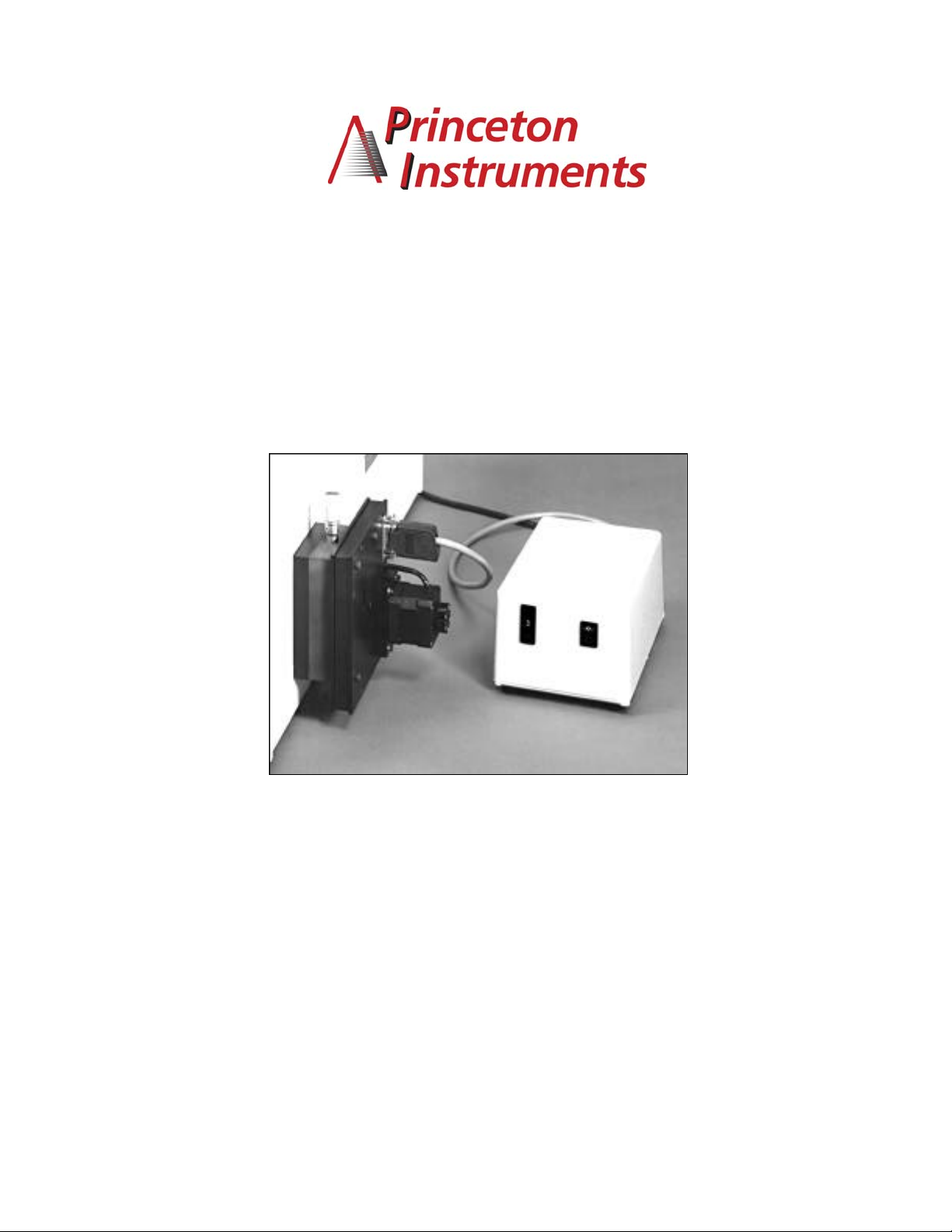
FA-448 SIX POSITION FILTER WHEEL
OPERATING INSTRUCTIONS
Rev: 1.597
Page 2

I. Description
II. Specifications
III. Installation
A. Mounting to Monochromator
B. Connecting Control Unit
C. Installing and Changing Filters
IV. Operation
A. Manual Operation with Controller or Terminal
B. Operation with Computer or Terminal
C. IEEE-488 Operation
V. Figures
C o n t e n t s
VI. Appendix A: Connector Wiring
VII. Warranty
1
Page 3

I. D e s c r i p t i o n
The FA-448 is a series of filter wheel assemblies which are available with and without installed order
sorting filters and with and without remote position control. This manual covers the following
models:
FA-448 Six position filter wheel.
Manual sample indexing.
Holds 6 samples or filters, each 1 inch diameter.
Does not include filters.
FA-448-1 Order sorting filter assembly.
320nm, 590nm, 665nm, and 715nm order sorting
filters mounted in the FA-448 filter wheel assembly. *
FA-448-2 Motorized six position filter wheel with stepping motor
and FA-448-4 controller. Enables computer controlled
filter indexing through RS-232 port and front panel
switch. Does not include filters.
FA-448-3 Motorized order sorting filter assembly. Same as
FA-448-2, except with order sorting filters installed.
Requires computer or terminal with RS-232 port for
external control. *
FA-448-4 Controller retrofit unit. For use with FA-448 and
FA-448-1 manual filter assemblies to allow computer
control or front panel switch control.
* Positions of order sorting filters in FA-448-1 and FA-448-3:
Position 1: Open
Position 2: 320nm cut-off filter
Position 3: 590nm cut-off filter
Position 4: 665nm cut-off filter
Position 5: 715nm cut-off filter
2
Page 4

II. FA-448 Series Filter Assembly Specifications
• Six position wheel
• One inch (1" ±0.005) diameter filters, maximum thickness =0 .200"
Controller specifications
• Control from computer or terminal through RS-232 port at 9600
• baud, no parity, 8 data bits, 1 stop bit and 1 start bit.
• Optional control from IEEE controller
Device #10*
• Time required for filter change = 2.5 seconds for adjacent filter positions.
Default Address - This address is user settable. See Section IV-C of this manual.
3
Page 5

III. I n s t a l l a t i o n
A. Mounting to Monochromator
The filter assembly is 3/4 of an inch thick. Therefore, if using a light source that is designed to
mount directly on the entrance slit housing and to focus the light on the entrance slit, it is
recommended that the filter assembly be mounted on the exit slit housing. If it is necessary to
install or change filters, do so before mounting the filter wheel to the SpectraPro™ (refer to step C).
The filter assembly is designed to mount directly to the SpectraPro™ slit housings or to be mounted
between the light source or detector and the slit housing. The filter assembly is attached to the slit
housing with three screws. The fourth screw is not used with the filter assembly. Assure that the (3)
8-32 mounting screws extend approximately 0.25 inch (6mm) beyond the filter assembly housing.
Orient the filter assembly so that the aperture slot is vertical and the motor is away from the
instrument housing. Mount the filter assembly or light source/detector to the desired slit housing
with (3) 8-32 screws.
B. Connecting Control Unit
Each control unit must be connected to an AC line of 115 vac. There is also a cable with a 15 pin
connector attached to each control unit which must be connected to the filter wheel assemblies. For
RS-232 operation of the filter assemblies, each control unit must be connected to separate RS-232
ports of a computer or terminal. Acton Research Corporation offers the following connecting cables:
CC-499-1 Cable for IBM-PC or XT compatible computers,
25 pin female connector to 9 pin male connector
CC-499-2 Cable for IBM-PC/AT or compatible computer,
9 pin female connector to 9 pin male connector
CC-499-3 Cable for computer terminal
25 pin male connector to 9 pin male connector
If none of the above cable assemblies are compatible with your computer or terminal, contact Acton
Research Corporation for a custom cable or one may be constructed using a standard DE-9P
connector at the filter controller end with the following connections:
pin # description
1 open
2 RD received data to the computer
3 TD transmitted data from the computer
4 open
5 ground
6 open
7 RTS connect these two
8 CTS pins together
9 open
For the optional IEEE-488 operation, connect a standard IEEE cable between the two control units
and connect an additional IEEE cable from one control unit to the IEEE controller.
4
Page 6

C. Installing and Changing Filters
To install or remove filters or samples, the following procedure is recommended:
1) If the filter assembly is mounted to the SpectraPro™, remove it and disconnect the cable, if
attached.
2) Place the filter assembly on a clean surface with the motor down. Refer to
Figure 1.
3) Using the 1/16" allen wrench supplied, remove the eight screws securing the cover plate to
the filter assembly (refer to Figure 1). While pushing on the end of the shaft with a pencil,
carefully remove the cover plate by lifting straight off the shaft. Caution: Aspacer is located
on the filter wheel shaft between the filter wheel and cover. If this spacer comes off with the
cover, place it back onto the shaft. Refer to Figure 2.
4) The six filter positions are now visible, refer to Figure 2. The filters are held in with split rings.
Determine the filters to be removed or the location for the filters to be installed. The filter
positions are marked 1 thru 6 on the wheel. Remove the split rings. Remove or install filters
as required. Replace the split ring assuring it is pushed firmly against the filters.
5) Assure that the spacer is on the filter wheel shaft and attach the cover plate with the eight
screws. The filter assembly is now ready for mounting to the SpectraPro™.
5
Page 7

IV. O p e r a t i o n
A. Remote Operation from Controller Unit
The filter positions of each filter wheel can be controlled using the thumbwheel switches on the
controller modules supplied with the filter assemblies. Connect the motor drive cable of the
controller to the motor connector of the filter wheel for each unit. Connect the control unit to an AC
line of the voltage listed on the back of the controller. The positions 0 - 6 may then be selected by
this switch.
B. Operation with RS-232 Computer or Terminal
Connect the motor drive of the control unit to the filter wheel and the RS-232 output of the control
unit to an RS-232 port of a computer or terminal. See section III-B for cable installation instructions.
The filter wheel with controller responds to commands from the computer or terminal in the form of
ASCII strings. The following two commands are used for controlling the filter position:
FILTER Controls the filter position and is used as follows:
3 FILTER <enter> sets filter wheel to position 3. Filter
positions 1 - 6 may be selected. Note that there must be a
after the number and the command must be terminated
with the enter or carriage return key. The filter will go
to the specified position in the direction which
requires the shortest move. When the move is
complete, the controller will respond with OK followed
by carriage return and line feed (hex AXCII sequence
20 6F 6B of OA). Also, the default condition is to echo each
character that is sent to the controller. If no echo is
desired, the command NO-ECHO will suppress the echo.
The command ECHO will return the controller to the
default echo state.
?FILTER Returns the current filter position. Typing ?FILTER <enter>
will cause the current filter position to be returned to the
computer and displayed.
FHOME Initializes the filter wheel to the first filter position.
This command is automatically executed at power-up.
The filter wheel controller keeps track of filter
position as long as power is applied. It should not be
necessary to execute this command under normal
circumstances, although it is available if desired. This
command follows the same format as in FILTER above
for entry and response.
6
Page 8

C. IEEE -488 Interface Option for Filter Controllers
The IEEE-488 interface option allows control of ARC Filter Control unit from the IEEE-488 bus. All
of the commands and status requests described in Section B - Operation with RS-232 Computer or
Terminal - are available through the IEEE-488 option. The following standard interface functions are
provided:
SH1, AH1, T2, L2, SR1, RL1 (NOTE: The local lockout command
is not accepted but the front panel is automatically locked out when
in remote), PP0, DC0, C0
The GPIB device identifier or address may be sent by dip switches on the interface board. The
switches are accessible on the bottom of the control unit by removing screws to the access plate.
The factory set device address is 10. The command ?ID will report back the current device address.
The following table shows the function of each switch position:
S1-1 on = address 1 decimal, off = address 0
S1-2 on = address 2 decimal, off = address 0
S1-3 on = address 4 decimal, off = address 0
S1-4 on = address 8 decimal, off = address 0
S1-5 on = address 16 decimal, off = address 0
S1-6 factory set to on
S1-7 factory set to off
S1-8 factory set to off
S1-9 factory set to on
S1-10 factory set to on
The last byte of each command string to the Filter Control unit must be a <CR> (hex OD). The end
message (EOI line) is accepted but not required. When the SpectraPro™ is a talker, each string
sent back to the controller ends with a <LF> (hex 0A) with the EOI line set.
The Filter Control unit will issue a service request based upon the contents of the service request
mask which is set by the SET-MASK command and read by the ?MASK command. The bits of the
mask are as follows:
bit 0 previously sent command is complete
bit 1 previous command generated an error
bit 7 previous command generated a response which is
now ready to be sent
The default value for the service request mask is ø, therefore, no service request is generated. To
change the mask to generate a service request on error or response ready, for example, issue the
command 130 SET-MASK <CR>. This new value is reset to the default value on reset or power-up.
The Filter Control unit responds to a serial poll with a status byte that uses the same bit pattern as
the service request mask shown above.
The following page is a Basic program listing illustrating the use of the filter controllers from a
National Instruments PC-IIA GPIB Controller.
7
Page 9

Program
1 CLEAR , 59000! : IBINIT1=59000! : IBINIT2=1BINIT1+3 : BLOAD “bib.m”,IBINIT1
2 CALL IBINIT1 (IBFIND, IBTRG, IBCLR, IBPCT, IBSIC, IBLOC, IBPPC, IBBNA, IBONL, IBRSC,
IB SRE, IBRSV, IBPAD, IBSAD, IBIST, IBDMA, IBEOS, IBTMO, IBEOT, IBRDF, IBWRTF, IBTRAP)
3 CALL IBINIT2 (IBGTS, IBCAC, IBWAIT, IBPOKE, IBWRT, IBWRTA, IBCMD, IBCMDA, IBRD, IBRDA, IBSTOP, IBRPP,
IBRSP, IBDIAG, IBXTRC, IBRDI, IBWRTI, IBRDIA, IBWRTIA, IBSTA%, IBERR%, IBCNT %)
4 GOTO 20
7 SAVE”DEVICE12",A:END
20 UDNAME$ ="DEV12"
30 CALL IBFIND (UDNAME$,UD%)
40 IF UD% < 0 THEN TOGO 200
43 INPUT “ENTER 1 TO GET ?FILTER, 2 TO SEND FILTER, 3 TO EXIT: “,Q
44 IF Q=1 THEN 50
45 IF Q=2 THEN 400
46 IF Q=3 THEN 430
47 GOTO 43
50 WRT$="?FILTER” +CHR$ (&HD)
60 CALL IBWRT (UD%,WRT$)
70 IF IBSTA% < 0 THEN GOTO 300
113 PRINT “IBSTA%="; IBSTA%
116 CALL IBRSP (UD%,SPR%)
117 IF ( (SPR% AND 129) <> 129 ) THEN 116
125 PRINT “SPR = “;SPR%
130 RD$=SPACE$(255)
140 CALL IBRD (UD%,RD$)
145 IF IBSTA% < 0 THEN GOTO 300
150 PRINT “ DATARECEIVED ="; LEFT$(RD$,IBCNT%);
160 PRINT “ STATUS =" ; IBSTA%
170 GOTO 43
200 PRINT “ibfind error “: STOP
300 PRINT “gpib function call error” : STOP
400 WRT$="2 FILTER” + CHR$ (&HD)
410 CALL IBWRT (UD%,WRT$)
420 IF IBSTA% < 0 THEN GOTO 300
425 GOTO 43
430 CALL IBLOC (UD%)
440 IF IBSTA% < 0 THEN GOTO 300
500 END
rem The above program is for use with the National Instruments
rem PC-IIA GPIB controller card for controlling filter wheel A.
rem to control filter wheel B, change line 20 to read “DEV13"
rem instead of “DEV12". The first three lines of the program
rem are merged from National Instruments file DECL.BAS and may
rem be different for your computer or GPIB controller card.
rem To operate, load and run as a BASIC program and enter
rem 1 to request the filter position, 2 to sent the filter
rem to position 2 ( this can be changed in line 400 or made
rem a variable ) or enter 3 to return the control unit to
rem local control mode ( thumbwheel switch ).
8
Page 10

V. F i g u r e s
Cover Screws
(1 of 8)
Shaft
Aperture Slot
Cover Plate
Detent Screw for
Manual Operation
Split Ring
(1 of 6)
Spacer
Filter or Sample
Position (1 of 6)
6 Position
Filter Wheel
9
Page 11

VI. Appendix A: Connector W i r i n g
Filter Wheel Drive Cable
J1 Filter Wheel
Pin #
1 Motor phase 1A
2 Motor phase 1C
3 Motor phase 1B
4 open
5 Motor phase 2A
6 Motor phase 2C
7 Motor phase 2B
8 open
9 open
10 Interrupter module OUT
11 Interrupter module GND
12 Interrupter module LED cathode
13 Interrupter module LED anode
14 Interrupter module +5vdc
15 Shield
NOTES:
1. J1 connector is Cannon DAMA-15P. Mating connector is Cannon DAMA-15S.
2. Cable is 24 AWG with overall shield.
3. Filter Driver Cable is permanently attached to the Filter Control Module.
10
Page 12

VII. Wa r r a n t y
Acton Research Corporation (ARC) certifies that this instrument was thoroughly tested and
inspected and found to meet the specifications furnished by ARC when it was shipped from
the factory.
Acton Research Corporation (ARC) instruments and accessories are warranted for a period
of one full year from date of delivery to be free from defects in material and workmanship and
to conforms to the specifications furnished by ARC. The corporation's obligation under this
warranty is limited to servicing or adjusting an instrument returned to the factory, prepaid, and
to repairing or replacing at the factory any part or parts thereof. All purchased items carry the
original manufacturers guarantee.
Acton Research Corporation shall not be liable for consequential damages resulting from
accident, alteration, misuse, improper installation, operation on low or excessive voltages or
any use in violation of the operating instructions furnished by ARC.
C e r t i f i c a t i o n
Wa r r a n t y
If any defect appears within the warranty period, the purchaser shall promptly notify ARC. No
material will be accepted for repair or replacement without prior authorization from ARC.
Upon such authorization and in accordance with instructions of Acton Research Corporation,
parts, materials or equipment for which repair or replacement is requested shall be returned
to ARC for examination, with shipping charges prepaid by the purchaser. Final determination
as to whether a product or part is actually defective rests with Acton Research Corporation.
In such cases where necessary repairs are not covered by this warranty, an estimate of repair
charges will be submitted to the purchaser before servicing the equipment.
Acton Research Corporation reserves the right to make changes or improvements upon its
products without imposing any obligations upon itself to install the same upon its products
previously manufactured.
This warranty is expressly in lieu of all other obligations or liabilities on the part of ARC, and
ARC neither assumes, nor authorizes any other person to assume for them, other obligations
or liability in connection with the sale of equipment manufactured by Acton Research
Corporation.
11
 Loading...