

4411-0139
Issue 4
September 11, 2014
4411-0139

Revision History
Issue Date List of Changes
4 September 11, 2014 Issue 4 of this document incorporates the following changes:
• Added information about the 1024EM and 1024EM(B) cameras.
3 October 11, 2013 Issue 3 of this document incorporates the following changes:
• Added Section 13.3.3.3, Custom, which details the use of custom RF gating
in LightField for PI-MAX4: 1024i-RF systems;
• Added PI-MAX4: 2048f information;
• Updated Appendix A, Technical Specifications;
• Added Section A.5, CCD Specifications.
2 July 24, 2013 Issue 2 of this document incorporates the following changes:
• Added Chapter 14, PI-MAX4: EM Family, and other EM-supporting
information throughout the document;
• Updated the Declarations of Conformity.
1.B February 11, 2013 Issue 1.B of this document incorporates the following changes:
• Editorial, graphic, and global nomenclature updates.
1.A February 27, 2012 This is the initial release of this document
Copyright 2012-2015 Princeton Instruments, a division of Roper Scientific, Inc.
All rights reserved. No part of this publication may be reproduced by any means without the written permission of Princeton Instruments, a division of
Roper Scientific, Inc. (“Princeton Instruments”.)
Printed in the United States of America.
Pentium is a registered trademark of Intel Corporation.
PVCAM is a registered trademark of Photometrics, Ltd. Corporation
Scientific Imaging ToolKit and SITK are trademarks of R Cubed Software Consultants, LLC.
IntelliCal, PICam, SuperSYNCHRO, and SyncMASTER are trademarks and IsoPlane, LightField, and PI-MAX are registered trademarks of Roper
Scientific, Inc.
Windows and Windows Vista are registered trademarks of Microsoft Corporation in the United States and/or other countries.
The information in this publication is believed to be accurate as of the publication release date. However, Princeton Instruments does not assume any
responsibility for any consequences including any damages resulting from the use thereof. The information contained herein is subject to change without
notice. Revision of this publication may be issued to incorporate such change.
3660 Quakerbridge Rd
Trenton, NJ 08619
TEL: 800-874-9789 / 609-587-9797
FAX: 609-587-1970

Table of Contents
Warnings and Cautions . . . . . . . . . . . . . . . . . . . . . . . . . . . . . . . . . 17
Alarm. . . . . . . . . . . . . . . . . . . . . . . . . . . . . . . . . . . . . . . . . . . . . . . . . . . . . . . . . . . . . .17
Chapter 1: Introduction. . . . . . . . . . . . . . . . . . . . . . . . . . . . . . . . . . . . . . . . . . . 19
1.1 PI-MAX4 System Components . . . . . . . . . . . . . . . . . . . . . . . . . . . . . . . . . . . . . . . .19
1.2 Summary of PI-MAX4 Data Acquisition. . . . . . . . . . . . . . . . . . . . . . . . . . . . . . . . .21
1.3 Safety Related Symbols Used in This Manual . . . . . . . . . . . . . . . . . . . . . . . . . . . . .22
1.4 Grounding and Safety. . . . . . . . . . . . . . . . . . . . . . . . . . . . . . . . . . . . . . . . . . . . . . . .23
1.4.1 Intensifier Modes and Safety . . . . . . . . . . . . . . . . . . . . . . . . . . . . . . . . . .24
1.4.2 Audible Alarm. . . . . . . . . . . . . . . . . . . . . . . . . . . . . . . . . . . . . . . . . . . . . .24
1.4.3 High Intensity Light Damage . . . . . . . . . . . . . . . . . . . . . . . . . . . . . . . . . .25
1.5 Precautions . . . . . . . . . . . . . . . . . . . . . . . . . . . . . . . . . . . . . . . . . . . . . . . . . . . . . . . .25
1.6 Cleaning and Maintenance . . . . . . . . . . . . . . . . . . . . . . . . . . . . . . . . . . . . . . . . . . . .26
1.6.1 Cleaning the Camera. . . . . . . . . . . . . . . . . . . . . . . . . . . . . . . . . . . . . . . . .26
1.6.2 Cleaning Optical Surfaces – Protective Window . . . . . . . . . . . . . . . . . . .26
1.6.3 Flushing and Refilling the CCD Chamber . . . . . . . . . . . . . . . . . . . . . . . .26
1.7 Repairs . . . . . . . . . . . . . . . . . . . . . . . . . . . . . . . . . . . . . . . . . . . . . . . . . . . . . . . . . . .26
1.8 About this Manual . . . . . . . . . . . . . . . . . . . . . . . . . . . . . . . . . . . . . . . . . . . . . . . . . .27
1.8.1 Conventions Used in this Manual. . . . . . . . . . . . . . . . . . . . . . . . . . . . . . .27
1.8.2 Manual Organization. . . . . . . . . . . . . . . . . . . . . . . . . . . . . . . . . . . . . . . . .27
Chapter 2: System Installation. . . . . . . . . . . . . . . . . . . . . . . . . . . . . . . . . . . . . 29
2.1 System Configuration Diagrams. . . . . . . . . . . . . . . . . . . . . . . . . . . . . . . . . . . . . . . .31
Chapter 3: System Setup . . . . . . . . . . . . . . . . . . . . . . . . . . . . . . . . . . . . . . . . . 33
3.1 Dangers and Warnings . . . . . . . . . . . . . . . . . . . . . . . . . . . . . . . . . . . . . . . . . . . . . . .33
3.2 Unpacking the System . . . . . . . . . . . . . . . . . . . . . . . . . . . . . . . . . . . . . . . . . . . . . . .33
3.3 Checking the Equipment and Parts Inventory . . . . . . . . . . . . . . . . . . . . . . . . . . . . .34
3.4 General System Requirements and Information. . . . . . . . . . . . . . . . . . . . . . . . . . . .35
3.4.1 Ventilation. . . . . . . . . . . . . . . . . . . . . . . . . . . . . . . . . . . . . . . . . . . . . . . . .35
3.4.2 Power Specifications. . . . . . . . . . . . . . . . . . . . . . . . . . . . . . . . . . . . . . . . .35
3.4.3 Host Computer Specifications . . . . . . . . . . . . . . . . . . . . . . . . . . . . . . . . .36
3.4.3.1 WinX Host Computer Requirements . . . . . . . . . . . . . . . . . . .36
3.4.3.2 LightField Host Computer Requirements. . . . . . . . . . . . . . . .37
3.5 Mounting the Camera . . . . . . . . . . . . . . . . . . . . . . . . . . . . . . . . . . . . . . . . . . . . . . . .38
3.5.1 Imaging Applications . . . . . . . . . . . . . . . . . . . . . . . . . . . . . . . . . . . . . . . .38
3.5.2 Spectroscopy Applications . . . . . . . . . . . . . . . . . . . . . . . . . . . . . . . . . . . .39
3.6 Application Software Installation . . . . . . . . . . . . . . . . . . . . . . . . . . . . . . . . . . . . . . .39
3.6.1 WinX Applications . . . . . . . . . . . . . . . . . . . . . . . . . . . . . . . . . . . . . . . . . .39
3.6.2 LightField Applications . . . . . . . . . . . . . . . . . . . . . . . . . . . . . . . . . . . . . .41
3.7 Connect the Circulator [Liquid-Cooled Cameras Only]. . . . . . . . . . . . . . . . . . . . . .42
3.8 Configure Default Camera System Parameters . . . . . . . . . . . . . . . . . . . . . . . . . . . .44
3.8.1 WinX (Versions 2.5.25.X or higher). . . . . . . . . . . . . . . . . . . . . . . . . . . . .44
3.8.2 LightField . . . . . . . . . . . . . . . . . . . . . . . . . . . . . . . . . . . . . . . . . . . . . . . . .45

4PI-MAX
®
4 System Manual Issue 4
Chapter 4: First Light . . . . . . . . . . . . . . . . . . . . . . . . . . . . . . . . . . . . . . . . . . . . . 47
4.1 Required Equipment and Cables . . . . . . . . . . . . . . . . . . . . . . . . . . . . . . . . . . . . . . . 47
4.2 Cable Connections. . . . . . . . . . . . . . . . . . . . . . . . . . . . . . . . . . . . . . . . . . . . . . . . . . 47
4.3 Before Turning on the System . . . . . . . . . . . . . . . . . . . . . . . . . . . . . . . . . . . . . . . . 48
4.4 Turning on the System . . . . . . . . . . . . . . . . . . . . . . . . . . . . . . . . . . . . . . . . . . . . . . 48
4.5 LightField First Light Instructions . . . . . . . . . . . . . . . . . . . . . . . . . . . . . . . . . . . . . 49
4.5.1 Assumptions . . . . . . . . . . . . . . . . . . . . . . . . . . . . . . . . . . . . . . . . . . . . . . 49
4.5.2 Getting Started. . . . . . . . . . . . . . . . . . . . . . . . . . . . . . . . . . . . . . . . . . . . . 49
4.5.3 Parameter Configuration . . . . . . . . . . . . . . . . . . . . . . . . . . . . . . . . . . . . . 50
4.5.4 Acquiring Data . . . . . . . . . . . . . . . . . . . . . . . . . . . . . . . . . . . . . . . . . . . . 52
4.5.5 Focusing . . . . . . . . . . . . . . . . . . . . . . . . . . . . . . . . . . . . . . . . . . . . . . . . . 54
4.6 WinX First Light Instructions . . . . . . . . . . . . . . . . . . . . . . . . . . . . . . . . . . . . . . . . . 55
4.6.1 Assumptions . . . . . . . . . . . . . . . . . . . . . . . . . . . . . . . . . . . . . . . . . . . . . . 55
4.6.2 Getting Started. . . . . . . . . . . . . . . . . . . . . . . . . . . . . . . . . . . . . . . . . . . . . 55
4.6.3 Configuring the Software . . . . . . . . . . . . . . . . . . . . . . . . . . . . . . . . . . . . 55
4.6.4 Initial Data Acquisition . . . . . . . . . . . . . . . . . . . . . . . . . . . . . . . . . . . . . . 59
4.6.5 Focusing . . . . . . . . . . . . . . . . . . . . . . . . . . . . . . . . . . . . . . . . . . . . . . . . . 60
Chapter 5: Gate Mode Operation . . . . . . . . . . . . . . . . . . . . . . . . . . . . . . . . . . . 61
5.1 Data Acquisition Sequence . . . . . . . . . . . . . . . . . . . . . . . . . . . . . . . . . . . . . . . . . . . 61
5.2 WinX System On/Off Sequences . . . . . . . . . . . . . . . . . . . . . . . . . . . . . . . . . . . . . . 62
5.3 Pre-Exposure Removal of Accumulated Charge . . . . . . . . . . . . . . . . . . . . . . . . . . 63
5.3.1 Dark Charge. . . . . . . . . . . . . . . . . . . . . . . . . . . . . . . . . . . . . . . . . . . . . . . 63
5.3.2 Cleaning. . . . . . . . . . . . . . . . . . . . . . . . . . . . . . . . . . . . . . . . . . . . . . . . . . 64
5.4 Phosphor Decay Delay . . . . . . . . . . . . . . . . . . . . . . . . . . . . . . . . . . . . . . . . . . . . . . 65
5.5 Temperature Control . . . . . . . . . . . . . . . . . . . . . . . . . . . . . . . . . . . . . . . . . . . . . . . . 66
5.5.1 Cooling Method. . . . . . . . . . . . . . . . . . . . . . . . . . . . . . . . . . . . . . . . . . . . 66
5.5.2 Necessary Cooling Precautions . . . . . . . . . . . . . . . . . . . . . . . . . . . . . . . . 67
5.5.3 Setting the Temperature. . . . . . . . . . . . . . . . . . . . . . . . . . . . . . . . . . . . . . 67
5.6 Exposure . . . . . . . . . . . . . . . . . . . . . . . . . . . . . . . . . . . . . . . . . . . . . . . . . . . . . . . . . 68
5.6.1 Exposure with an Image Intensifier. . . . . . . . . . . . . . . . . . . . . . . . . . . . . 68
5.6.1.1 Exposure Timing . . . . . . . . . . . . . . . . . . . . . . . . . . . . . . . . . . 68
5.6.2 Saturation. . . . . . . . . . . . . . . . . . . . . . . . . . . . . . . . . . . . . . . . . . . . . . . . . 69
5.7 Background Subtraction . . . . . . . . . . . . . . . . . . . . . . . . . . . . . . . . . . . . . . . . . . . . . 69
5.8 Readout of the Array. . . . . . . . . . . . . . . . . . . . . . . . . . . . . . . . . . . . . . . . . . . . . . . . 70
5.8.1 Interline CCD Readout . . . . . . . . . . . . . . . . . . . . . . . . . . . . . . . . . . . . . . 71
5.8.2 Full-Frame CCD Readout . . . . . . . . . . . . . . . . . . . . . . . . . . . . . . . . . . . . 74
5.8.3 Binned Readout (Hardware Binning) . . . . . . . . . . . . . . . . . . . . . . . . . . . 76
5.8.3.1 CCD Type and Readout Port(s) . . . . . . . . . . . . . . . . . . . . . . 77
5.8.3.2 LightField and Partial Frame ROI Binning. . . . . . . . . . . . . . 80
5.9 Software Binning. . . . . . . . . . . . . . . . . . . . . . . . . . . . . . . . . . . . . . . . . . . . . . . . . . . 82
5.10 Controller Gain {Analog Gain} . . . . . . . . . . . . . . . . . . . . . . . . . . . . . . . . . . . . . . . 83
5.11 Digitization . . . . . . . . . . . . . . . . . . . . . . . . . . . . . . . . . . . . . . . . . . . . . . . . . . . . . . . 83
5.12 Logic Out Control . . . . . . . . . . . . . . . . . . . . . . . . . . . . . . . . . . . . . . . . . . . . . . . . . . 84
5.13 WinX Experiment Setup . . . . . . . . . . . . . . . . . . . . . . . . . . . . . . . . . . . . . . . . . . . . . 86
5.13.1 Main Tab . . . . . . . . . . . . . . . . . . . . . . . . . . . . . . . . . . . . . . . . . . . . . . . . . 86
5.13.2 Timing Tab . . . . . . . . . . . . . . . . . . . . . . . . . . . . . . . . . . . . . . . . . . . . . . . 87

Table of Contents 5
5.14 LightField Experiment Setup . . . . . . . . . . . . . . . . . . . . . . . . . . . . . . . . . . . . . . . . . .90
5.14.1 Common Acquisition Settings Expander . . . . . . . . . . . . . . . . . . . . . . . . .90
5.14.2 Region of Interest Expander . . . . . . . . . . . . . . . . . . . . . . . . . . . . . . . . . . .91
5.14.3 Trigger Expander . . . . . . . . . . . . . . . . . . . . . . . . . . . . . . . . . . . . . . . . . . .92
5.14.4 SuperSYNCHRO Timing Expander . . . . . . . . . . . . . . . . . . . . . . . . . . . . .93
Chapter 6: LightField and Gated Operation . . . . . . . . . . . . . . . . . . . . . . . . . . 95
6.1 Gating . . . . . . . . . . . . . . . . . . . . . . . . . . . . . . . . . . . . . . . . . . . . . . . . . . . . . . . . . . . .95
6.2 Safety Precautions . . . . . . . . . . . . . . . . . . . . . . . . . . . . . . . . . . . . . . . . . . . . . . . . . .96
6.2.1 Intensifier Mode . . . . . . . . . . . . . . . . . . . . . . . . . . . . . . . . . . . . . . . . . . . .96
6.2.2 Alarms. . . . . . . . . . . . . . . . . . . . . . . . . . . . . . . . . . . . . . . . . . . . . . . . . . . .96
6.3 Timing Mode . . . . . . . . . . . . . . . . . . . . . . . . . . . . . . . . . . . . . . . . . . . . . . . . . . . . . .97
6.4 Micro-Channel Plate (MCP) Bracket Pulsing . . . . . . . . . . . . . . . . . . . . . . . . . . . . .98
6.4.1 Bracket Pulsing in LIF Measurements . . . . . . . . . . . . . . . . . . . . . . . . . . .99
6.4.2 Bracket Pulsing in Nanosecond Pump Probe Experiments . . . . . . . . . . .99
6.4.3 Limitations of Bracket Pulse Gating. . . . . . . . . . . . . . . . . . . . . . . . . . . . .99
6.4.4 Impact of Bracket Pulsing on Delay . . . . . . . . . . . . . . . . . . . . . . . . . . . .100
6.4.5 Configuration . . . . . . . . . . . . . . . . . . . . . . . . . . . . . . . . . . . . . . . . . . . . .101
6.5 Experiments . . . . . . . . . . . . . . . . . . . . . . . . . . . . . . . . . . . . . . . . . . . . . . . . . . . . . .102
6.5.1 Swept Gate Experiment [Fixed Width, Variable Delay] . . . . . . . . . . . .103
6.5.1.1 Experiment Supplies the Master Clock . . . . . . . . . . . . . . . .103
6.5.1.2 SyncMASTER1 Supplies the Master Clock. . . . . . . . . . . . .112
6.5.2 Single Shot Experiment . . . . . . . . . . . . . . . . . . . . . . . . . . . . . . . . . . . . .113
6.5.3 Swept Gate Experiment [Variable Width, Variable Delay] . . . . . . . . . .117
6.5.4 Static Gate Experiment [Fixed Width, Fixed Delay] . . . . . . . . . . . . . . .117
Chapter 7: WinX and Gated Operation . . . . . . . . . . . . . . . . . . . . . . . . . . . . . 119
7.1 Gating . . . . . . . . . . . . . . . . . . . . . . . . . . . . . . . . . . . . . . . . . . . . . . . . . . . . . . . . . . .119
7.2 Safety Precautions . . . . . . . . . . . . . . . . . . . . . . . . . . . . . . . . . . . . . . . . . . . . . . . . .120
7.2.1 Intensifier Mode . . . . . . . . . . . . . . . . . . . . . . . . . . . . . . . . . . . . . . . . . . .120
7.2.2 Alarms. . . . . . . . . . . . . . . . . . . . . . . . . . . . . . . . . . . . . . . . . . . . . . . . . . .121
7.3 Timing Mode . . . . . . . . . . . . . . . . . . . . . . . . . . . . . . . . . . . . . . . . . . . . . . . . . . . . .121
7.4 Micro-Channel Plate (MCP) Bracket Pulsing . . . . . . . . . . . . . . . . . . . . . . . . . . . .122
7.4.1 Bracket Pulsing in LIF Measurements . . . . . . . . . . . . . . . . . . . . . . . . . .123
7.4.2 Bracket Pulsing in Nanosecond Pump Probe Experiments . . . . . . . . . .124
7.4.3 Limitations of Bracket Pulse Gating. . . . . . . . . . . . . . . . . . . . . . . . . . . .124
7.4.4 Impact of Bracket Pulsing on Delay . . . . . . . . . . . . . . . . . . . . . . . . . . . .125
7.4.5 Configuration . . . . . . . . . . . . . . . . . . . . . . . . . . . . . . . . . . . . . . . . . . . . .125
7.5 Experiments . . . . . . . . . . . . . . . . . . . . . . . . . . . . . . . . . . . . . . . . . . . . . . . . . . . . . .126
7.5.1 Swept Gate Experiment [Fixed Width, Variable Delay] . . . . . . . . . . . .127
7.5.1.1 Experiment Supplies the Master Clock . . . . . . . . . . . . . . . .127
7.5.1.2 SyncMASTER1 Supplies the Master Clock. . . . . . . . . . . . .141
7.5.2 Single Shot Experiment . . . . . . . . . . . . . . . . . . . . . . . . . . . . . . . . . . . . .142
7.5.3 Swept Gate Experiment [Variable Width, Variable Delay] . . . . . . . . . .146
7.5.4 Static Gate Experiment [Fixed Width, Fixed Delay] . . . . . . . . . . . . . . .146
Chapter 8: Timing Generator . . . . . . . . . . . . . . . . . . . . . . . . . . . . . . . . . . . . . 147
8.1 Pulse Set . . . . . . . . . . . . . . . . . . . . . . . . . . . . . . . . . . . . . . . . . . . . . . . . . . . . . . . . .147
8.1.1 Supported Timing Generator Trigger Modes . . . . . . . . . . . . . . . . . . . . .148
8.2 Single Sequence . . . . . . . . . . . . . . . . . . . . . . . . . . . . . . . . . . . . . . . . . . . . . . . . . . .148
8.2.1 Supported Timing Generator Trigger Modes . . . . . . . . . . . . . . . . . . . . .149

6PI-MAX
®
4 System Manual Issue 4
Chapter 9: LightField and Dual Image Feature . . . . . . . . . . . . . . . . . . . . . . . 151
9.1 Requirements. . . . . . . . . . . . . . . . . . . . . . . . . . . . . . . . . . . . . . . . . . . . . . . . . . . . . 151
9.2 Interline CCD Operation . . . . . . . . . . . . . . . . . . . . . . . . . . . . . . . . . . . . . . . . . . . . 152
9.3 Trigger Setup. . . . . . . . . . . . . . . . . . . . . . . . . . . . . . . . . . . . . . . . . . . . . . . . . . . . . 153
9.3.1 Trigger Response. . . . . . . . . . . . . . . . . . . . . . . . . . . . . . . . . . . . . . . . . . 153
9.3.2 Trigger Source . . . . . . . . . . . . . . . . . . . . . . . . . . . . . . . . . . . . . . . . . . . . 154
9.3.2.1 Internal Trigger Source . . . . . . . . . . . . . . . . . . . . . . . . . . . . 154
9.3.2.2 External Trigger Source . . . . . . . . . . . . . . . . . . . . . . . . . . . 154
9.4 Configure a Single Trigger DIF Experiment. . . . . . . . . . . . . . . . . . . . . . . . . . . . . 155
9.4.1 Hardware . . . . . . . . . . . . . . . . . . . . . . . . . . . . . . . . . . . . . . . . . . . . . . . . 155
9.4.2 Software Configuration and Operation . . . . . . . . . . . . . . . . . . . . . . . . . 156
9.5 Configure a Dual Trigger DIF Experiment . . . . . . . . . . . . . . . . . . . . . . . . . . . . . . 158
9.5.1 Hardware . . . . . . . . . . . . . . . . . . . . . . . . . . . . . . . . . . . . . . . . . . . . . . . . 158
9.5.2 Software Setup and Operation. . . . . . . . . . . . . . . . . . . . . . . . . . . . . . . . 158
9.6 Tips and Tricks . . . . . . . . . . . . . . . . . . . . . . . . . . . . . . . . . . . . . . . . . . . . . . . . . . . 160
Chapter 10: WinX and Dual Image Feature . . . . . . . . . . . . . . . . . . . . . . . . . . . 161
10.1 Requirements. . . . . . . . . . . . . . . . . . . . . . . . . . . . . . . . . . . . . . . . . . . . . . . . . . . . . 161
10.2 Interline CCD Operation . . . . . . . . . . . . . . . . . . . . . . . . . . . . . . . . . . . . . . . . . . . . 161
10.3 Timing Modes . . . . . . . . . . . . . . . . . . . . . . . . . . . . . . . . . . . . . . . . . . . . . . . . . . . . 162
10.4 Configure a Single Trigger DIF Experiment. . . . . . . . . . . . . . . . . . . . . . . . . . . . . 162
10.4.1 Hardware . . . . . . . . . . . . . . . . . . . . . . . . . . . . . . . . . . . . . . . . . . . . . . . . 162
10.4.2 Software. . . . . . . . . . . . . . . . . . . . . . . . . . . . . . . . . . . . . . . . . . . . . . . . . 162
10.4.3 Operation . . . . . . . . . . . . . . . . . . . . . . . . . . . . . . . . . . . . . . . . . . . . . . . . 163
10.5 Configure a Dual Trigger DIF Experiment . . . . . . . . . . . . . . . . . . . . . . . . . . . . . . 168
10.5.1 Hardware . . . . . . . . . . . . . . . . . . . . . . . . . . . . . . . . . . . . . . . . . . . . . . . . 168
10.5.2 Software. . . . . . . . . . . . . . . . . . . . . . . . . . . . . . . . . . . . . . . . . . . . . . . . . 168
10.5.3 Operation . . . . . . . . . . . . . . . . . . . . . . . . . . . . . . . . . . . . . . . . . . . . . . . . 168
10.6 Tips and Tricks . . . . . . . . . . . . . . . . . . . . . . . . . . . . . . . . . . . . . . . . . . . . . . . . . . . 174
Chapter 11: MCP Gating Option . . . . . . . . . . . . . . . . . . . . . . . . . . . . . . . . . . . . 175
11.1 Setup and Operation . . . . . . . . . . . . . . . . . . . . . . . . . . . . . . . . . . . . . . . . . . . . . . . 176
11.2 Gain Variation. . . . . . . . . . . . . . . . . . . . . . . . . . . . . . . . . . . . . . . . . . . . . . . . . . . . 177
11.3 Fluorescence Experiment . . . . . . . . . . . . . . . . . . . . . . . . . . . . . . . . . . . . . . . . . . . 177
11.4 Cabling for MCP Gated Operation . . . . . . . . . . . . . . . . . . . . . . . . . . . . . . . . . . . . 177
Chapter 12: Picosecond Gating Option . . . . . . . . . . . . . . . . . . . . . . . . . . . . . . 179
12.1 Activating Picosecond Operation . . . . . . . . . . . . . . . . . . . . . . . . . . . . . . . . . . . . . 179
12.2 Gain and Gate Width. . . . . . . . . . . . . . . . . . . . . . . . . . . . . . . . . . . . . . . . . . . . . . . 179
12.3 MONITOR Operation . . . . . . . . . . . . . . . . . . . . . . . . . . . . . . . . . . . . . . . . . . . . . . 180
12.4 Repetition Rate Issues . . . . . . . . . . . . . . . . . . . . . . . . . . . . . . . . . . . . . . . . . . . . . . 180
12.5 Timing . . . . . . . . . . . . . . . . . . . . . . . . . . . . . . . . . . . . . . . . . . . . . . . . . . . . . . . . . . 181
12.6 Methods for Finding a Short Optical Pulse. . . . . . . . . . . . . . . . . . . . . . . . . . . . . . 181

Table of Contents 7
Chapter 13: PI-MAX4: 1024i-RF and RF Modulation . . . . . . . . . . . . . . . . . . . 183
13.1 Basics of RF Modulation on Intensified CCDs . . . . . . . . . . . . . . . . . . . . . . . . . . .183
13.2 Advantages of PI-MAX4: 1024i-RF . . . . . . . . . . . . . . . . . . . . . . . . . . . . . . . . . . .184
13.3 RF Experiment Design in LightField . . . . . . . . . . . . . . . . . . . . . . . . . . . . . . . . . . .185
13.3.1 Requirements . . . . . . . . . . . . . . . . . . . . . . . . . . . . . . . . . . . . . . . . . . . . .185
13.3.2 Trigger Response . . . . . . . . . . . . . . . . . . . . . . . . . . . . . . . . . . . . . . . . . .185
13.3.3 Gating Mode . . . . . . . . . . . . . . . . . . . . . . . . . . . . . . . . . . . . . . . . . . . . . .186
13.3.3.1 Repetitive . . . . . . . . . . . . . . . . . . . . . . . . . . . . . . . . . . . . . . .186
13.3.3.2 Sequential . . . . . . . . . . . . . . . . . . . . . . . . . . . . . . . . . . . . . . .188
13.3.3.3 Custom . . . . . . . . . . . . . . . . . . . . . . . . . . . . . . . . . . . . . . . . .190
13.3.4 Phase Modulation Sorting Add-In . . . . . . . . . . . . . . . . . . . . . . . . . . . . .197
13.4 PI-MAX4: 1024i-RF Rear Panel Information . . . . . . . . . . . . . . . . . . . . . . . . . . . .200
13.4.1 PI-MAX4: 1024i-RF Power Supply Rear Panel Information. . . . . . . . .202
13.5 RF Modulator Specifications . . . . . . . . . . . . . . . . . . . . . . . . . . . . . . . . . . . . . . . . .203
Chapter 14: PI-MAX4: EM Family . . . . . . . . . . . . . . . . . . . . . . . . . . . . . . . . . . . 205
14.1 Electron Multiplication. . . . . . . . . . . . . . . . . . . . . . . . . . . . . . . . . . . . . . . . . . . . . .205
14.1.1 Enabling EM . . . . . . . . . . . . . . . . . . . . . . . . . . . . . . . . . . . . . . . . . . . . . .207
14.1.2 EM Gain Mode . . . . . . . . . . . . . . . . . . . . . . . . . . . . . . . . . . . . . . . . . . . .208
14.1.2.1 Optimal . . . . . . . . . . . . . . . . . . . . . . . . . . . . . . . . . . . . . . . . .208
14.1.2.2 Manual . . . . . . . . . . . . . . . . . . . . . . . . . . . . . . . . . . . . . . . . .209
14.2 Kinetics . . . . . . . . . . . . . . . . . . . . . . . . . . . . . . . . . . . . . . . . . . . . . . . . . . . . . . . . . .211
14.2.1 Masking. . . . . . . . . . . . . . . . . . . . . . . . . . . . . . . . . . . . . . . . . . . . . . . . . .211
14.2.2 Trigger Sources. . . . . . . . . . . . . . . . . . . . . . . . . . . . . . . . . . . . . . . . . . . .213
14.2.3 Image/Frame Acquisition . . . . . . . . . . . . . . . . . . . . . . . . . . . . . . . . . . . .213
14.2.4 Data Readout. . . . . . . . . . . . . . . . . . . . . . . . . . . . . . . . . . . . . . . . . . . . . .215
14.2.5 Binning . . . . . . . . . . . . . . . . . . . . . . . . . . . . . . . . . . . . . . . . . . . . . . . . . .215
14.2.5.1 File Storage Conventions . . . . . . . . . . . . . . . . . . . . . . . . . . .218
14.2.6 Configuring Kinetics. . . . . . . . . . . . . . . . . . . . . . . . . . . . . . . . . . . . . . . .219
14.2.7 Cleaning the CCD . . . . . . . . . . . . . . . . . . . . . . . . . . . . . . . . . . . . . . . . . .220
14.2.8 Configuring a Kinetics Experiment . . . . . . . . . . . . . . . . . . . . . . . . . . . .221
14.2.8.1 Configuring the Software Parameters: . . . . . . . . . . . . . . . . .222
14.3 Photon Detection . . . . . . . . . . . . . . . . . . . . . . . . . . . . . . . . . . . . . . . . . . . . . . . . . .223
14.3.1 Configuring Photon Detection . . . . . . . . . . . . . . . . . . . . . . . . . . . . . . . .224
14.4 High Speed Camera Add-in . . . . . . . . . . . . . . . . . . . . . . . . . . . . . . . . . . . . . . . . . .225
14.4.1 Configuring the High Speed Camera . . . . . . . . . . . . . . . . . . . . . . . . . . .226
Chapter 15: Tips and Tricks . . . . . . . . . . . . . . . . . . . . . . . . . . . . . . . . . . . . . . . 229
15.1 Overexposure Protection . . . . . . . . . . . . . . . . . . . . . . . . . . . . . . . . . . . . . . . . . . . .229
15.2 Signal Delay . . . . . . . . . . . . . . . . . . . . . . . . . . . . . . . . . . . . . . . . . . . . . . . . . . . . . .230
15.2.1 Time Budgets . . . . . . . . . . . . . . . . . . . . . . . . . . . . . . . . . . . . . . . . . . . . .230
15.2.2 Measuring Coincidence. . . . . . . . . . . . . . . . . . . . . . . . . . . . . . . . . . . . . .231
15.2.3 Adjusting the Signal Delay . . . . . . . . . . . . . . . . . . . . . . . . . . . . . . . . . . .232
15.2.4 Optimizing the Gate Width and Delay . . . . . . . . . . . . . . . . . . . . . . . . . .232
15.3 Lasers . . . . . . . . . . . . . . . . . . . . . . . . . . . . . . . . . . . . . . . . . . . . . . . . . . . . . . . . . . .233
15.3.1 Free Running Lasers . . . . . . . . . . . . . . . . . . . . . . . . . . . . . . . . . . . . . . . .233
15.3.2 Triggered Lasers . . . . . . . . . . . . . . . . . . . . . . . . . . . . . . . . . . . . . . . . . . .233
15.3.3 Jitter. . . . . . . . . . . . . . . . . . . . . . . . . . . . . . . . . . . . . . . . . . . . . . . . . . . . .234
15.4 Inhibiting the Pulser During Readout . . . . . . . . . . . . . . . . . . . . . . . . . . . . . . . . . . .234

8PI-MAX
®
4 System Manual Issue 4
15.5 Lens Performance . . . . . . . . . . . . . . . . . . . . . . . . . . . . . . . . . . . . . . . . . . . . . . . . . 234
15.5.1 Throughput . . . . . . . . . . . . . . . . . . . . . . . . . . . . . . . . . . . . . . . . . . . . . . 234
15.5.2 Depth of Field . . . . . . . . . . . . . . . . . . . . . . . . . . . . . . . . . . . . . . . . . . . . 234
15.6 Baseline Signal . . . . . . . . . . . . . . . . . . . . . . . . . . . . . . . . . . . . . . . . . . . . . . . . . . . 235
15.7 Temperature Lock . . . . . . . . . . . . . . . . . . . . . . . . . . . . . . . . . . . . . . . . . . . . . . . . . 235
15.8 Intensifier Alarm . . . . . . . . . . . . . . . . . . . . . . . . . . . . . . . . . . . . . . . . . . . . . . . . . . 235
Chapter 16: Component Descriptions . . . . . . . . . . . . . . . . . . . . . . . . . . . . . . . 237
16.1 Mount Adapters. . . . . . . . . . . . . . . . . . . . . . . . . . . . . . . . . . . . . . . . . . . . . . . . . . . 237
16.2 Switches, Connectors, and Indicators . . . . . . . . . . . . . . . . . . . . . . . . . . . . . . . . . . 238
16.2.1 AUX I/O . . . . . . . . . . . . . . . . . . . . . . . . . . . . . . . . . . . . . . . . . . . . . . . . 239
16.2.2 AUX Out . . . . . . . . . . . . . . . . . . . . . . . . . . . . . . . . . . . . . . . . . . . . . . . . 239
16.2.3 AUX Power [PI-MAX4: 1024i-RF only] . . . . . . . . . . . . . . . . . . . . . . . 239
16.2.4 Coolant Ports . . . . . . . . . . . . . . . . . . . . . . . . . . . . . . . . . . . . . . . . . . . . . 239
16.2.5 Error LED . . . . . . . . . . . . . . . . . . . . . . . . . . . . . . . . . . . . . . . . . . . . . . . 240
16.2.6 Fan . . . . . . . . . . . . . . . . . . . . . . . . . . . . . . . . . . . . . . . . . . . . . . . . . . . . . 240
16.2.7 Gig-E . . . . . . . . . . . . . . . . . . . . . . . . . . . . . . . . . . . . . . . . . . . . . . . . . . . 240
16.2.8 I.I.T. PWR On/Off Switch. . . . . . . . . . . . . . . . . . . . . . . . . . . . . . . . . . . 240
16.2.9 Logic Out. . . . . . . . . . . . . . . . . . . . . . . . . . . . . . . . . . . . . . . . . . . . . . . . 241
16.2.10 Mon RF Out [PI-MAX4: 1024i-RF only] . . . . . . . . . . . . . . . . . . . . . . . 241
16.2.11 Monitor . . . . . . . . . . . . . . . . . . . . . . . . . . . . . . . . . . . . . . . . . . . . . . . . . 241
16.2.12 Power Connector . . . . . . . . . . . . . . . . . . . . . . . . . . . . . . . . . . . . . . . . . . 241
16.2.13 Ready Out . . . . . . . . . . . . . . . . . . . . . . . . . . . . . . . . . . . . . . . . . . . . . . . 241
16.2.14 Thermoelectric Cooler. . . . . . . . . . . . . . . . . . . . . . . . . . . . . . . . . . . . . . 242
16.2.15 Trigger In. . . . . . . . . . . . . . . . . . . . . . . . . . . . . . . . . . . . . . . . . . . . . . . . 242
16.2.16 User RF Out [PI-MAX4: 1024i-RF only] . . . . . . . . . . . . . . . . . . . . . . . 242
16.3 Gig-E Ethernet Card . . . . . . . . . . . . . . . . . . . . . . . . . . . . . . . . . . . . . . . . . . . . . . . 242
16.4 Extender Bracket Kit. . . . . . . . . . . . . . . . . . . . . . . . . . . . . . . . . . . . . . . . . . . . . . . 242
16.5 CoolCUBE
16.6 Spectrograph (Option). . . . . . . . . . . . . . . . . . . . . . . . . . . . . . . . . . . . . . . . . . . . . . 243
16.7 Cables . . . . . . . . . . . . . . . . . . . . . . . . . . . . . . . . . . . . . . . . . . . . . . . . . . . . . . . . . . 243
16.8 Tubing . . . . . . . . . . . . . . . . . . . . . . . . . . . . . . . . . . . . . . . . . . . . . . . . . . . . . . . . . . 243
16.9 Application Software. . . . . . . . . . . . . . . . . . . . . . . . . . . . . . . . . . . . . . . . . . . . . . . 244
16.10 User Manuals. . . . . . . . . . . . . . . . . . . . . . . . . . . . . . . . . . . . . . . . . . . . . . . . . . . . . 245
Coolant Circulator (Option). . . . . . . . . . . . . . . . . . . . . . . . . . . . . . . 243
II
Chapter 17: Troubleshooting . . . . . . . . . . . . . . . . . . . . . . . . . . . . . . . . . . . . . . 247
17.1 Alarm Sounds Repetitively . . . . . . . . . . . . . . . . . . . . . . . . . . . . . . . . . . . . . . . . . . 248
17.2 Alarm Sounds Sporadically. . . . . . . . . . . . . . . . . . . . . . . . . . . . . . . . . . . . . . . . . . 248
17.3 Baseline Signal Suddenly Changes by > 1000 ADU . . . . . . . . . . . . . . . . . . . . . . 248
17.4 Camera Is Not Responding . . . . . . . . . . . . . . . . . . . . . . . . . . . . . . . . . . . . . . . . . . 248
17.5 Camera Stops Working . . . . . . . . . . . . . . . . . . . . . . . . . . . . . . . . . . . . . . . . . . . . . 249
17.6 Camera1 (or similar name) in Camera Name field . . . . . . . . . . . . . . . . . . . . . . . . 249
17.7 Cooling Troubleshooting. . . . . . . . . . . . . . . . . . . . . . . . . . . . . . . . . . . . . . . . . . . . 250
17.7.1 Temperature Lock Cannot be Achieved or Maintained. . . . . . . . . . . . . 250
17.8 Data Loss or Serial Violation . . . . . . . . . . . . . . . . . . . . . . . . . . . . . . . . . . . . . . . . 251
17.9 Error Occurs at Computer Power Up . . . . . . . . . . . . . . . . . . . . . . . . . . . . . . . . . . 251
17.10 Ethernet Network is Not Accessible . . . . . . . . . . . . . . . . . . . . . . . . . . . . . . . . . . . 252
17.10.1 LightField Applications. . . . . . . . . . . . . . . . . . . . . . . . . . . . . . . . . . . . . 252
17.10.2 WinX Applications . . . . . . . . . . . . . . . . . . . . . . . . . . . . . . . . . . . . . . . . 253
17.11 Excessive Readout Noise . . . . . . . . . . . . . . . . . . . . . . . . . . . . . . . . . . . . . . . . . . . 253
17.12 Gating Pulse Artifact Strings Displayed . . . . . . . . . . . . . . . . . . . . . . . . . . . . . . . . 254

Table of Contents 9
Appendix A: Technical Specifications . . . . . . . . . . . . . . . . . . . . . . . . . . . . . . . 255
A.1 Mechanical Dimensions . . . . . . . . . . . . . . . . . . . . . . . . . . . . . . . . . . . . . . . . . . . . .255
A.2 Power Specifications . . . . . . . . . . . . . . . . . . . . . . . . . . . . . . . . . . . . . . . . . . . . . . .255
A.3 Environmental Specifications. . . . . . . . . . . . . . . . . . . . . . . . . . . . . . . . . . . . . . . . .256
A.4 Intensifier Specifications . . . . . . . . . . . . . . . . . . . . . . . . . . . . . . . . . . . . . . . . . . . .256
A.5 CCD Specifications . . . . . . . . . . . . . . . . . . . . . . . . . . . . . . . . . . . . . . . . . . . . . . . .256
A.6 AUX I/O Interface . . . . . . . . . . . . . . . . . . . . . . . . . . . . . . . . . . . . . . . . . . . . . . . . .258
A.6.1 AUX I/O Cable . . . . . . . . . . . . . . . . . . . . . . . . . . . . . . . . . . . . . . . . . . . .260
A.7 CoolCUBE
Circulator Specifications. . . . . . . . . . . . . . . . . . . . . . . . . . . . . . . . . .261
II
Appendix B: Outline Drawings . . . . . . . . . . . . . . . . . . . . . . . . . . . . . . . . . . . . . 263
B.1 PI-MAX4: 1024i/1024f/2048f/1024x256. . . . . . . . . . . . . . . . . . . . . . . . . . . . . . . .263
B.2 PI-MAX4: 512 EM/512 EM(B) . . . . . . . . . . . . . . . . . . . . . . . . . . . . . . . . . . . . . . .266
B.3 PI-MAX4 Power Supply. . . . . . . . . . . . . . . . . . . . . . . . . . . . . . . . . . . . . . . . . . . . .269
B.4 PI-MAX4: 1024i-RF. . . . . . . . . . . . . . . . . . . . . . . . . . . . . . . . . . . . . . . . . . . . . . . .270
B.5 PI-MAX4: 1024i-RF Power Supply . . . . . . . . . . . . . . . . . . . . . . . . . . . . . . . . . . . .273
B.6 CoolCUBE
Circulator. . . . . . . . . . . . . . . . . . . . . . . . . . . . . . . . . . . . . . . . . . . . . .274
II
Appendix C: WinX/LightField Cross Reference . . . . . . . . . . . . . . . . . . . . . . . . 275
C.1 WinX-to-LightField Terminology . . . . . . . . . . . . . . . . . . . . . . . . . . . . . . . . . . . . .275
C.2 LightField to WinX. . . . . . . . . . . . . . . . . . . . . . . . . . . . . . . . . . . . . . . . . . . . . . . . .277
Appendix D: Extender Bracket Kit . . . . . . . . . . . . . . . . . . . . . . . . . . . . . . . . . . 279
Appendix E: C- and F-Mount Information . . . . . . . . . . . . . . . . . . . . . . . . . . . . 281
E.1 C-Mount Lens Information. . . . . . . . . . . . . . . . . . . . . . . . . . . . . . . . . . . . . . . . . . .281
E.1.1 Installation. . . . . . . . . . . . . . . . . . . . . . . . . . . . . . . . . . . . . . . . . . . . . . . .281
E.1.2 Removal . . . . . . . . . . . . . . . . . . . . . . . . . . . . . . . . . . . . . . . . . . . . . . . . .281
E.2 F-Mount Lens Adapter . . . . . . . . . . . . . . . . . . . . . . . . . . . . . . . . . . . . . . . . . . . . . .282
E.2.1 Installation. . . . . . . . . . . . . . . . . . . . . . . . . . . . . . . . . . . . . . . . . . . . . . . .282
E.2.2 Removal . . . . . . . . . . . . . . . . . . . . . . . . . . . . . . . . . . . . . . . . . . . . . . . . .282
E.3 Camera Orientation. . . . . . . . . . . . . . . . . . . . . . . . . . . . . . . . . . . . . . . . . . . . . . . . .283
E.4 Focusing C- and F-Mount Lenses. . . . . . . . . . . . . . . . . . . . . . . . . . . . . . . . . . . . . .283
Appendix F: Spectrograph Mount Information . . . . . . . . . . . . . . . . . . . . . . . . 285
F.1 Mount PI-MAX4 to an Acton SpectraPro Series Spectrograph . . . . . . . . . . . . . . .285
F.1.1 Required Tools and Equipment. . . . . . . . . . . . . . . . . . . . . . . . . . . . . . . .285
F.1.2 Procedure . . . . . . . . . . . . . . . . . . . . . . . . . . . . . . . . . . . . . . . . . . . . . . . .285
F.2 Mount a PI-MAX4 to an IsoPlane SCT-320 Spectrograph . . . . . . . . . . . . . . . . . .287
F.2.1 Required Tools and Equipment. . . . . . . . . . . . . . . . . . . . . . . . . . . . . . . .287
F.2.2 Procedure . . . . . . . . . . . . . . . . . . . . . . . . . . . . . . . . . . . . . . . . . . . . . . . .287
F.3 Spectrograph-Camera Rotational Alignment and Focusing. . . . . . . . . . . . . . . . . .288
F.3.1 Aligning and Focusing an Acton SpectraPro Series Spectrograph. . . . .288
F.3.2 Align and Focus an IsoPlane SCT-320 Spectrograph. . . . . . . . . . . . . . .290

10 PI-MAX® 4 System Manual Issue 4
Appendix G: Accessories . . . . . . . . . . . . . . . . . . . . . . . . . . . . . . . . . . . . . . . . . . 293
G.1 Accessory Kits. . . . . . . . . . . . . . . . . . . . . . . . . . . . . . . . . . . . . . . . . . . . . . . . . . . . 293
G.2 Adapter Kits . . . . . . . . . . . . . . . . . . . . . . . . . . . . . . . . . . . . . . . . . . . . . . . . . . . . . 293
G.3 Quick Start Guide . . . . . . . . . . . . . . . . . . . . . . . . . . . . . . . . . . . . . . . . . . . . . . . . . 294
G.4 Standard C-, F-, and Spectroscopy-Mount Adapters . . . . . . . . . . . . . . . . . . . . . . 294
G.5 Spectroscopy-Mount for IVUV and NVUV Cameras . . . . . . . . . . . . . . . . . . . . . 295
G.5.1 Installation Procedure . . . . . . . . . . . . . . . . . . . . . . . . . . . . . . . . . . . . . . 295
G.6 Optical Distance from Mounting Face to Image Plane . . . . . . . . . . . . . . . . . . . . . 297
Appendix H: Glossary . . . . . . . . . . . . . . . . . . . . . . . . . . . . . . . . . . . . . . . . . . . . . 299
Declaration of Conformity . . . . . . . . . . . . . . . . . . . . . . . . . . . . . . 305
Warranty & Service . . . . . . . . . . . . . . . . . . . . . . . . . . . . . . . . . . . . 309
Limited Warranty. . . . . . . . . . . . . . . . . . . . . . . . . . . . . . . . . . . . . . . . . . . . . . . . . . . 309
Basic Limited One (1) Year Warranty . . . . . . . . . . . . . . . . . . . . . . . . . . . . . . . 309
Limited One (1) Year Warranty on Refurbished or Discontinued Products. . . 309
XP Vacuum Chamber Limited Lifetime Warranty . . . . . . . . . . . . . . . . . . . . . . 309
Sealed Chamber Integrity Limited 12 Month Warranty . . . . . . . . . . . . . . . . . . 310
Vacuum Integrity Limited 12 Month Warranty . . . . . . . . . . . . . . . . . . . . . . . . 310
Image Intensifier Detector Limited One Year Warranty. . . . . . . . . . . . . . . . . . 310
X-Ray Detector Limited One Year Warranty . . . . . . . . . . . . . . . . . . . . . . . . . . 310
Software Limited Warranty. . . . . . . . . . . . . . . . . . . . . . . . . . . . . . . . . . . . . . . . 310
Owner's Manual and Troubleshooting . . . . . . . . . . . . . . . . . . . . . . . . . . . . . . . 311
Your Responsibility. . . . . . . . . . . . . . . . . . . . . . . . . . . . . . . . . . . . . . . . . . . . . . 311
Contact Information. . . . . . . . . . . . . . . . . . . . . . . . . . . . . . . . . . . . . . . . . . . . . . . . . 312
List of Figures
Figure 1-1: Typical PI-MAX4 System Components . . . . . . . . . . . . . . . . . . . . . . . . 19
Figure 1-2: Major Components of the Intensifier-CCD . . . . . . . . . . . . . . . . . . . . . . 21
Figure 2-1: Typical PI-MAX4 System Diagram. . . . . . . . . . . . . . . . . . . . . . . . . . . . 31
Figure 2-2: Typical PI-MAX4: 1024i-RF System Diagram . . . . . . . . . . . . . . . . . . . 31
Figure 3-1: Typical WinView/32 Setup Dialog . . . . . . . . . . . . . . . . . . . . . . . . . . . . 40
Figure 3-2: Typical LightField InstallShield Wizard Dialog . . . . . . . . . . . . . . . . . . 41
Figure 3-3: Typical CoolCUBE
Figure 3-4: Typical WinX Camera Detection Wizard Dialog . . . . . . . . . . . . . . . . . 44
Figure 4-1: LightField Desktop: Available Devices. . . . . . . . . . . . . . . . . . . . . . . . . 50
Figure 4-2: Camera Icon in Experiment Devices Area . . . . . . . . . . . . . . . . . . . . . . . 51
Figure 4-3: LightField Desktop View Area . . . . . . . . . . . . . . . . . . . . . . . . . . . . . . . 52
Figure 4-4: Typical SuperSYNCHRO Timing Expander . . . . . . . . . . . . . . . . . . . . . 53
Figure 4-5: LightField View Area Displaying an Acquired Image . . . . . . . . . . . . . 54
Figure 4-6: Typical WinX Pulsers Dialog . . . . . . . . . . . . . . . . . . . . . . . . . . . . . . . . 55
Figure 4-7: Typical SuperSYNCHRO Dialog: Trigger In Tab. . . . . . . . . . . . . . . . . 56
Figure 4-8: Typical SuperSYNCHRO Dialog: Gating Tab . . . . . . . . . . . . . . . . . . . 56
Figure 4-9: Typical Repetitive Gating Setup Dialog . . . . . . . . . . . . . . . . . . . . . . . . 57
Figure 4-10: Typical Experiment Setup Dialog: Main Tab . . . . . . . . . . . . . . . . . . . . 58
Figure 4-11: Typical Experiment Setup Dialog: ADC Tab . . . . . . . . . . . . . . . . . . . . 58
Figure 4-12: Typical Experiment Setup Dialog: ROI Setup Tab . . . . . . . . . . . . . . . . 59
Figure 4-13: Sample Acquired Test Image. . . . . . . . . . . . . . . . . . . . . . . . . . . . . . . . . 60
Figure 5-1: Block Diagram: Signal Path in a Standard PI-MAX4 System. . . . . . . . 62
Circulator. . . . . . . . . . . . . . . . . . . . . . . . . . . . . . . 42
II

List of Figures 11
Figure 5-2: Clean Cycles in Internal Trigger Mode of Operation . . . . . . . . . . . . . . .64
Figure 5-3: WinX: Phosphor Decay Delay. . . . . . . . . . . . . . . . . . . . . . . . . . . . . . . . .66
Figure 5-4: LightField: Phosphor Decay Delay Parameters. . . . . . . . . . . . . . . . . . . .66
Figure 5-5: Interline CCD Readout . . . . . . . . . . . . . . . . . . . . . . . . . . . . . . . . . . . . . .71
Figure 5-6: Step 1: Non-Overlapped, Early Exposure . . . . . . . . . . . . . . . . . . . . . . . .72
Figure 5-7: Step 2: Non-Overlapped, Early Readout . . . . . . . . . . . . . . . . . . . . . . . . .72
Figure 5-8: Step 3: Non-Overlapped, Transfer to Output Node. . . . . . . . . . . . . . . . .73
Figure 5-9: Step 4: Non-Overlapped, End of Readout. . . . . . . . . . . . . . . . . . . . . . . .73
Figure 5-10: Full Frame CCD Readout . . . . . . . . . . . . . . . . . . . . . . . . . . . . . . . . . . . .74
Figure 5-11: Dual Port Readout: 2 × 2 Binning of Interline CCD . . . . . . . . . . . . . . . .77
Figure 5-12: Dual Port Readout: LightField Setting, 2x2 Binning, Interline CCD . . .78
Figure 5-13: Single Port Readout: 2 × 2 Binning of Full Frame CCD. . . . . . . . . . . . .78
Figure 5-14: Experiment Setup: ROI Configuration Dialog . . . . . . . . . . . . . . . . . . . .79
Figure 5-15: Typical Edit Regions of Interest Window . . . . . . . . . . . . . . . . . . . . . . . .80
Figure 5-16: Single Port Readout: Partial Frame, 2×2 Binning, Interline CCD . . . . .81
Figure 5-17: Dual Port Readout: LightField Settings, 5×3 Binning, Interline CCD . .82
Figure 5-18: Typical PI-MAX4 Hardware Setup Dialog . . . . . . . . . . . . . . . . . . . . . . .84
Figure 5-19: Timing Diagram: Shutter {Shutter Open}, Read Out {Reading Out},
Acquiring {Acquiring} . . . . . . . . . . . . . . . . . . . . . . . . . . . . . . . . . . . . . .84
Figure 5-20: Typical Experiment Setup Dialog: Main Tab . . . . . . . . . . . . . . . . . . . . .86
Figure 5-21: Typical Experiment Setup Dialog: Timing Tab . . . . . . . . . . . . . . . . . . .87
Figure 5-22: Fast Mode/Slow Mode Flow Charts . . . . . . . . . . . . . . . . . . . . . . . . . . . .88
Figure 5-23: Typical Common Acquisition Settings Expander . . . . . . . . . . . . . . . . . .90
Figure 5-24: Typical Region of Interest Expander. . . . . . . . . . . . . . . . . . . . . . . . . . . .91
Figure 5-25: Typical Trigger Expander: Internal Trigger Source Parameters . . . . . . .92
Figure 5-26: Typical Trigger Expander: External Trigger Source Parameters . . . . . .92
Figure 5-27: SuperSYNCHRO Timing Expander . . . . . . . . . . . . . . . . . . . . . . . . . . . .93
Figure 6-1: Timing Diagram: MCP Bracket Pulsing . . . . . . . . . . . . . . . . . . . . . . . . .98
Figure 6-2: Timing Diagram: MCP Bracket Pulsing . . . . . . . . . . . . . . . . . . . . . . . .101
Figure 6-3: Typical PI-MAX4 Experiments. . . . . . . . . . . . . . . . . . . . . . . . . . . . . . .102
Figure 6-4: Block/Timing Diagram: Swept Gate Experiment . . . . . . . . . . . . . . . . .104
Figure 6-5: Typical Sensor Cleaning Fly-out Pane . . . . . . . . . . . . . . . . . . . . . . . . .104
Figure 6-6: Typical Spectrometer Expanders. . . . . . . . . . . . . . . . . . . . . . . . . . . . . .105
Figure 6-7: Typical Region of Interest Expander: Full Sensor . . . . . . . . . . . . . . . .105
Figure 6-8: Typical Common Acquisition Settings Expander . . . . . . . . . . . . . . . . .106
Figure 6-9: Typical Analog to Digital Conversion Expander . . . . . . . . . . . . . . . . .106
Figure 6-10: Typical Trigger Expander . . . . . . . . . . . . . . . . . . . . . . . . . . . . . . . . . . .107
Figure 6-11: Typical Region of Interest Expander: Full Sensor Binned . . . . . . . . . .108
Figure 6-12: Trigger Expander: External Trigger Source Configuration. . . . . . . . . .108
Figure 6-13: Typical SuperSYNCHRO Timing Expander. . . . . . . . . . . . . . . . . . . . .109
Figure 6-14: Typical SuperSYNCHRO Timing: SyncMASTER On. . . . . . . . . . . . .110
Figure 6-15: Typical Experiment Results: Frame Cross Section . . . . . . . . . . . . . . . .111
Figure 6-16: Block Diagram: SyncMASTER1 as Master Clock . . . . . . . . . . . . . . . .112
Figure 6-17: Timing Diagram: SyncMASTER1 as Master Clock . . . . . . . . . . . . . . .112
Figure 6-18: Block Diagram: Single Shot Experiment . . . . . . . . . . . . . . . . . . . . . . .113
Figure 6-19: Cleaning Cycles, Cleaning and Skipping Expander . . . . . . . . . . . . . . .114
Figure 6-20: Common Acquisition Settings Expander: Intensifier Gain . . . . . . . . . .114
Figure 6-21: Typical Repetitive Gating Setup: 100 ns Width, 25 ns Delay. . . . . . . .115
Figure 6-22: Single Shot Result: Fluorescence Spot, Width = 100 ns,
Delay = 10 ns. . . . . . . . . . . . . . . . . . . . . . . . . . . . . . . . . . . . . . . . . . . . .116

12 PI-MAX® 4 System Manual Issue 4
Figure 6-23: Single Shot Result: Fluorescence Spot, Width = 100 ns,
Delay = 10 ns, Binned Vertically. . . . . . . . . . . . . . . . . . . . . . . . . . . . . 116
Figure 6-24: Repetitive Gating Setup Dialog . . . . . . . . . . . . . . . . . . . . . . . . . . . . . . 117
Figure 7-1: Timing Diagram: MCP Bracket Pulsing . . . . . . . . . . . . . . . . . . . . . . . 123
Figure 7-2: Timing Diagram: MCP Bracket Pulsing . . . . . . . . . . . . . . . . . . . . . . . 125
Figure 7-3: Typical PI-MAX4 Experiments . . . . . . . . . . . . . . . . . . . . . . . . . . . . . . 126
Figure 7-4: Block/Timing Diagram: Swept Gate Experiment . . . . . . . . . . . . . . . . 128
Figure 7-5: Typical Hardware Setup Dialog. . . . . . . . . . . . . . . . . . . . . . . . . . . . . . 129
Figure 7-6: Typical WinSpec/32 Installation Sequence: Acton 300I
Spectrograph. . . . . . . . . . . . . . . . . . . . . . . . . . . . . . . . . . . . . . . . . . . . . 130
Figure 7-7: Typical Move Spectrograph Dialog . . . . . . . . . . . . . . . . . . . . . . . . . . . 131
Figure 7-8: Typical Experiment Setup Dialog: Main Tab . . . . . . . . . . . . . . . . . . . 131
Figure 7-9: Typical Experiment Setup Dialog: Timing Tab. . . . . . . . . . . . . . . . . . 132
Figure 7-10: Typical Experiment Setup Dialog: ADC Tab . . . . . . . . . . . . . . . . . . . 133
Figure 7-11: Typical Experiment Setup Dialog: ROI Tab . . . . . . . . . . . . . . . . . . . . 133
Figure 7-12: Typical WinX Pulsers Dialog . . . . . . . . . . . . . . . . . . . . . . . . . . . . . . . 134
Figure 7-13: Typical SuperSYNCHRO Dialog: Trigger In Tab. . . . . . . . . . . . . . . . 134
Figure 7-14: Typical WinX Pulsers Dialog . . . . . . . . . . . . . . . . . . . . . . . . . . . . . . . 135
Figure 7-15: Typical SuperSYNCHRO Dialog: Trigger In Tab. . . . . . . . . . . . . . . . 135
Figure 7-16: Typical SuperSYNCHRO Dialog: Gating Tab . . . . . . . . . . . . . . . . . . 136
Figure 7-17: Typical Sequential Gating Setup Dialog . . . . . . . . . . . . . . . . . . . . . . . 136
Figure 7-18: Typical View Width/Delay Sequence Dialog . . . . . . . . . . . . . . . . . . . 137
Figure 7-19: Typical SuperSYNCHRO Dialog: Trigger Out Tab . . . . . . . . . . . . . . 138
Figure 7-20: Experiment Setup: Timing Tab . . . . . . . . . . . . . . . . . . . . . . . . . . . . . . 139
Figure 7-21: Experiment Setup: Main Tab . . . . . . . . . . . . . . . . . . . . . . . . . . . . . . . . 139
Figure 7-22: Typical Experiment Results Shown in 3-D . . . . . . . . . . . . . . . . . . . . . 140
Figure 7-23: Block Diagram: SyncMASTER1 as Master Clock . . . . . . . . . . . . . . . 141
Figure 7-24: Timing Diagram: SyncMASTER1 as Master Clock . . . . . . . . . . . . . . 141
Figure 7-25: Block Diagram: Single Shot Experiment . . . . . . . . . . . . . . . . . . . . . . . 142
Figure 7-26: Hardware Setup Dialog: Cleans/Skips Tab . . . . . . . . . . . . . . . . . . . . . 143
Figure 7-27: Experiment Setup Dialog: Main Tab . . . . . . . . . . . . . . . . . . . . . . . . . . 144
Figure 7-28: Typical Repetitive Gating Setup Dialog . . . . . . . . . . . . . . . . . . . . . . . 144
Figure 7-29: Single Shot Result: Fluorescence Spot, Width = 100 ns,
Delay = 10 ns . . . . . . . . . . . . . . . . . . . . . . . . . . . . . . . . . . . . . . . . . . . . 145
Figure 7-30: Single Shot Result: Fluorescence Spot, Width = 100 ns,
Delay = 10 ns, Binned Vertically. . . . . . . . . . . . . . . . . . . . . . . . . . . . . 145
Figure 7-31: Repetitive Gating Setup Dialog . . . . . . . . . . . . . . . . . . . . . . . . . . . . . . 146
Figure 8-1: Timing Diagram: Pulse Set . . . . . . . . . . . . . . . . . . . . . . . . . . . . . . . . . 147
Figure 8-2: Timing Diagram: Trigger Per Pulse. . . . . . . . . . . . . . . . . . . . . . . . . . . 148
Figure 8-3: Timing Diagrams: Three Repetition Sequence . . . . . . . . . . . . . . . . . . 148
Figure 8-4: Timing Diagram: 3 Repetition Sequence, Trigger per Pulse . . . . . . . . 149
Figure 9-1: Readout Expander . . . . . . . . . . . . . . . . . . . . . . . . . . . . . . . . . . . . . . . . 151
Figure 9-2: Common Acquisition Settings Expander. . . . . . . . . . . . . . . . . . . . . . . 152
Figure 9-3: Trigger Expander . . . . . . . . . . . . . . . . . . . . . . . . . . . . . . . . . . . . . . . . . 153
Figure 9-4: SuperSYNCHRO Timing Expander: DIF Operation. . . . . . . . . . . . . . 154
Figure 9-5: Block Diagram: DIF Experiment . . . . . . . . . . . . . . . . . . . . . . . . . . . . . 155
Figure 9-6: Timing Diagram: DIF Operation, Single Trigger . . . . . . . . . . . . . . . . 156
Figure 9-7: Block Diagram: DIF Experiment . . . . . . . . . . . . . . . . . . . . . . . . . . . . . 158
Figure 9-8: Timing Diagram: DIF Operation, Dual Trigger. . . . . . . . . . . . . . . . . . 158
Figure 10-1: Block Diagram: DIF Experiment. . . . . . . . . . . . . . . . . . . . . . . . . . . . . 162

List of Figures 13
Figure 10-2: Timing Diagram: DIF Operation, Single Trigger . . . . . . . . . . . . . . . . .163
Figure 10-3: WinX Hardware Setup Dialog: Controller/Camera Tab . . . . . . . . . . . .164
Figure 10-4: WinX Experiment Setup Dialog: Main Tab . . . . . . . . . . . . . . . . . . . . .164
Figure 10-5: WinX Experiment Setup Dialog: Timing Tab. . . . . . . . . . . . . . . . . . . .165
Figure 10-6: WinX Pulsers Dialog . . . . . . . . . . . . . . . . . . . . . . . . . . . . . . . . . . . . . . .165
Figure 10-7: WinX SuperSYNCHRO Dialog: Gating Tab . . . . . . . . . . . . . . . . . . . .166
Figure 10-8: WinX DIF Gating Setup Dialog . . . . . . . . . . . . . . . . . . . . . . . . . . . . . .166
Figure 10-9: WinX SuperSYNCHRO Dialog: Trigger In Tab. . . . . . . . . . . . . . . . . .167
Figure 10-10: WinX SuperSYNCHRO Dialog: Trigger Out Tab . . . . . . . . . . . . . . . .167
Figure 10-11: Block Diagram: DIF Experiment. . . . . . . . . . . . . . . . . . . . . . . . . . . . . .168
Figure 10-12: Timing Diagram: DIF Operation, Dual Trigger . . . . . . . . . . . . . . . . . .169
Figure 10-13: WinX Hardware Setup Dialog: Controller/Camera Tab . . . . . . . . . . . .169
Figure 10-14: WinX Experiment Setup Dialog: Main Tab . . . . . . . . . . . . . . . . . . . . .170
Figure 10-15: WinX Experiment Setup Dialog: Timing Tab. . . . . . . . . . . . . . . . . . . .171
Figure 10-16: WinX Pulsers Dialog. . . . . . . . . . . . . . . . . . . . . . . . . . . . . . . . . . . . . . .171
Figure 10-17: WinX SuperSYNCHRO Dialog: Gating Tab . . . . . . . . . . . . . . . . . . . .172
Figure 10-18: WinX DIF Gating Setup Dialog: Dual Trigger . . . . . . . . . . . . . . . . . . .172
Figure 10-19: WinX SuperSYNCHRO Dialog: Trigger In Tab. . . . . . . . . . . . . . . . . .173
Figure 10-20: WinX SuperSYNCHRO Dialog: Trigger Out Tab . . . . . . . . . . . . . . . .173
Figure 11-1: Timing Diagram: Normal Gated Operation. . . . . . . . . . . . . . . . . . . . . .175
Figure 11-2: Timing Diagram: MCP Bracket Pulsing Operation. . . . . . . . . . . . . . . .175
Figure 11-3: Timing Diagram: MCP Gated Operation for Gen II Intensifiers . . . . .176
Figure 11-4: QE Curves: Gen II Intensifiers . . . . . . . . . . . . . . . . . . . . . . . . . . . . . . .176
Figure 11-5: Block Diagram: MCP Gated Operation Cabling . . . . . . . . . . . . . . . . . .177
Figure 11-6: Timing Diagram: MCP Gated Operation . . . . . . . . . . . . . . . . . . . . . . .178
Figure 13-1: System Diagram: RF Operation. . . . . . . . . . . . . . . . . . . . . . . . . . . . . . .184
Figure 13-2: SuperSYNCHRO Timing Expander: Repetitive Gating Mode. . . . . . .187
Figure 13-3: SuperSYNCHRO Timing Expander: Sequential Gating Mode. . . . . . .188
Figure 13-4: SuperSYNCHRO Timing Expander: Custom Gating Mode . . . . . . . . .190
Figure 13-5: Typical Edit Custom Phase Modulations Window . . . . . . . . . . . . . . . .191
Figure 13-6: Add a Single Modulation Phase . . . . . . . . . . . . . . . . . . . . . . . . . . . . . .192
Figure 13-7: Add Phase Sweep . . . . . . . . . . . . . . . . . . . . . . . . . . . . . . . . . . . . . . . . .194
Figure 13-8: Typical Modulation Phase Curve . . . . . . . . . . . . . . . . . . . . . . . . . . . . .195
Figure 13-9: Typical Modulation Phase Curve with Points Shuffled . . . . . . . . . . . .195
Figure 13-10: Typical Manage Add-ins Dialog . . . . . . . . . . . . . . . . . . . . . . . . . . . . . .197
Figure 13-11: Typical Phase Modulation Sorting Add-in . . . . . . . . . . . . . . . . . . . . . .198
Figure 13-12: Typical Phase Modulation Sorting Add-in Button: Data Toolbar. . . . .198
Figure 13-13: Typical Sort Phases Dialog . . . . . . . . . . . . . . . . . . . . . . . . . . . . . . . . . .199
Figure 13-14: Typical Sort Phases Dialog: SPE File Specified . . . . . . . . . . . . . . . . . .199
Figure 13-15: PI-MAX4: 1024i-RF Rear Panel . . . . . . . . . . . . . . . . . . . . . . . . . . . . . .200
Figure 13-16: PI-MAX4: 1024i-RF Power Supply Rear Panel . . . . . . . . . . . . . . . . . .202
Figure 14-1: Block Diagram: EMCCD with Dual Output Registers . . . . . . . . . . . . .206
Figure 14-2: Typical emICCD Hardware Stackup . . . . . . . . . . . . . . . . . . . . . . . . . . .207
Figure 14-3: Enabling Electron Multiplication . . . . . . . . . . . . . . . . . . . . . . . . . . . . .207
Figure 14-4: Typical emICCD Gain Configuration Field . . . . . . . . . . . . . . . . . . . . .208
Figure 14-5: Typical Intensifier Gain Configuration Fields. . . . . . . . . . . . . . . . . . . .209
Figure 14-6: Typical EM Gain Configuration Field. . . . . . . . . . . . . . . . . . . . . . . . . .209
Figure 14-7: Typical EM Gain Configuration Display for EM Gain > 100. . . . . . . .210
Figure 14-8: Configuring Readout Mode . . . . . . . . . . . . . . . . . . . . . . . . . . . . . . . . . .211
Figure 14-9: Typical Full-Frame and Frame Transfer CCDs, Kinetics Masking . . .212

14 PI-MAX® 4 System Manual Issue 4
Figure 14-13: File Storage Convention. . . . . . . . . . . . . . . . . . . . . . . . . . . . . . . . . . . . 218
Figure 14-14: Configuring Readout Mode . . . . . . . . . . . . . . . . . . . . . . . . . . . . . . . . . 219
Figure 14-15: Configuring Trigger Response. . . . . . . . . . . . . . . . . . . . . . . . . . . . . . . 220
Figure 14-16: Block Diagram: Typical Kinetics Experiment. . . . . . . . . . . . . . . . . . . 221
Figure 14-17: Typical Common Acquisition Settings Expander . . . . . . . . . . . . . . . . 224
Figure 14-18: Typical Thresholding and Clipping Configuration Parameters . . . . . . 224
Figure 14-19: Typical High Speed Camera Expander . . . . . . . . . . . . . . . . . . . . . . . . 225
Figure 14-20: Typical High Speed Camera Spectroscopy Settings . . . . . . . . . . . . . . 226
Figure 14-21: Typical High Speed Camera Imaging Settings . . . . . . . . . . . . . . . . . . 226
Figure 14-22: Typical Previous and Current Frame Rate Information . . . . . . . . . . . . 226
Figure 14-23: Typical Configuration Options: Time Stamping, Frame Tracking . . . 227
Figure 16-1: PI-MAX4 Rear Panel . . . . . . . . . . . . . . . . . . . . . . . . . . . . . . . . . . . . . . 238
Figure 16-2: PI-MAX4: 1024i-RF Rear Panel . . . . . . . . . . . . . . . . . . . . . . . . . . . . . 238
Figure 17-1: Camera1 in Camera Name Field . . . . . . . . . . . . . . . . . . . . . . . . . . . . . 249
Figure 17-2: Editing Camera Name in Notepad . . . . . . . . . . . . . . . . . . . . . . . . . . . . 249
Figure 17-3: Updated Hardware Setup Dialog . . . . . . . . . . . . . . . . . . . . . . . . . . . . . 250
Figure 17-4: eBUS Driver Installation Tool Dialog for LightField . . . . . . . . . . . . . 252
Figure 17-5: eBUS Driver Installation Tool Dialog for WinX . . . . . . . . . . . . . . . . . 253
Figure 17-6: Typical Diagonal Line of Gating Pulse Artifacts. . . . . . . . . . . . . . . . . 254
Figure A-1: AUX I/O Connector Pinout . . . . . . . . . . . . . . . . . . . . . . . . . . . . . . . . . 258
Figure A-2: AUX I/O Interface Cable (Part Number 6050-0660). . . . . . . . . . . . . . 260
Figure D-1: Extender Bracket Kit Mounted to a PI-MAX4 . . . . . . . . . . . . . . . . . . 279
Figure E-1: F-Mount (Nikon) Lens Adapter . . . . . . . . . . . . . . . . . . . . . . . . . . . . . . 282
Figure G-1: Magnetic Screwdriver with Reversible Flat and Phillips Bit. . . . . . . . 293
Figure G-2: Standard PI-MAX4 Mount Adapters . . . . . . . . . . . . . . . . . . . . . . . . . . 294
Figure G-3: Standard, IVUV, and NVUV Spectroscopy Mounts . . . . . . . . . . . . . . 295
Figure G-4: Positioning the 2.739” (ID) O-ring . . . . . . . . . . . . . . . . . . . . . . . . . . . 296
Figure G-5: Positioning the 2.614” (ID) O-ring . . . . . . . . . . . . . . . . . . . . . . . . . . . 296

List of Tables 15
List of Tables
Revision History . . . . . . . . . . . . . . . . . . . . . . . . . . . . . . . . . . . . . . . . . . . . . . . . . . . . . . . .2
Table 2-1: PI-MAX4 System Installation Procedure. . . . . . . . . . . . . . . . . . . . . . . . . .29
Table 6-1: Internal Sync Information for Gated Operation. . . . . . . . . . . . . . . . . . . . .97
Table 6-2: Single Shot Experiment Time Budget . . . . . . . . . . . . . . . . . . . . . . . . . . .113
Table 7-1: Internal Sync Information for Gated Operation. . . . . . . . . . . . . . . . . . . .122
Table 7-2: Single Shot Experiment Time Budget . . . . . . . . . . . . . . . . . . . . . . . . . . .142
Table 12-1: Typical Picosecond Gating Information: PI-MAX4:1024i . . . . . . . . . . .180
Table 13-1: Phase Sweep Information for Sweep > 360° . . . . . . . . . . . . . . . . . . . . . .193
Table 13-2: PI-MAX4: 1024i-RF Connectors, Indicators, and Switches . . . . . . . . . .201
Table 13-3: PI-MAX4: 1024i-RF Power Supply Connectors, Indicators, and
Switches . . . . . . . . . . . . . . . . . . . . . . . . . . . . . . . . . . . . . . . . . . . . . . . . . .203
Table 14-1: Mask/Window Sizes for 16 x 16 CCD, Full Frame . . . . . . . . . . . . . . . . .212
Table 17-1: Issues with Recommended Troubleshooting Procedures. . . . . . . . . . . . .247
Table A-1: Input Power Specifications: External PI-MAX4 Power Supply . . . . . . .255
Table A-2: PI-MAX4 Environmental Specifications . . . . . . . . . . . . . . . . . . . . . . . . .256
Table A-3: CCD Array Specifications for Electron Multiplied PI-MAX4
Detectors. . . . . . . . . . . . . . . . . . . . . . . . . . . . . . . . . . . . . . . . . . . . . . . . . .256
Table A-4: CCD Array Specifications for non-EM PI-MAX4 Detectors . . . . . . . . .257
Table A-5: AUX I/O Interface TTL Signal Specifications . . . . . . . . . . . . . . . . . . . .258
Table A-6: AUX I/O Connector Pinout and Signal Descriptions. . . . . . . . . . . . . . . .258
Table A-7: AUX I/O Interface Cable Pinout and Signal Information . . . . . . . . . . . .260
Table C-1: WinX-to-LightField Cross Reference . . . . . . . . . . . . . . . . . . . . . . . . . . .275
Table C-2: LightField-to-WinX Cross Reference . . . . . . . . . . . . . . . . . . . . . . . . . . .277
Table G-1: Adapter Kit Information. . . . . . . . . . . . . . . . . . . . . . . . . . . . . . . . . . . . . .293

16 PI-MAX® 4 System Manual Issue 4
This page is intentionally blank.

Warnings and Cautions
WARNING!
NOTE:
CAUTION!
!
When biased ON, intensified CCD cameras, such as the PI-MAX®4
can be irreparably damaged if continuously exposed to light levels
higher than twice the A/D saturation level. Therefore, it is critical that
conditions not be created which could result in damage to the
intensifier. Although intensified cameras are less prone to damage from
background light when operated in gated mode, they are at significant
risk to damage from high-intensity light sources such as a laser.
High-intensity sources can damage the intensifier before protection
circuits have time to respond, or even cause spot damage without the
protection circuits acting at all. If a sustained alarm indication occurs
when the controller is turned on, either completely cover the intensifier
to reduce the light to halt the overload condition, or further reduce the
laboratory illumination until safe operating conditions have been
established.
Alarm
To reduce the risk of camera damage, the PI-MAX4 camera is equipped with an audible alarm
in the camera head, activated when the intensity of light falling on the image intensifier
exceeds a preset threshold. While the alarm is sounding, the photocathode is disabled.
Immediately switch the I.I.T. switch (on the back of the PI-MAX4) to the OFF position.
Cover the camera window and only switch the I.I.T. switch to ON after the illumination level
has been lowered. If the alarm sounds continuously even when the illumination level is
adequately low, shut the system down and contact the factory for guidance.
It is normal for the alarm to sound briefly when the system is first
turned on.
Discontinue operation and contact the factory immediately if
sporadic or continuous unwarranted alarms continue. They may
be an indication of intensifier damage or another condition which
may require immediate attention.
17

18 PI-MAX® 4 System Manual Issue 4
This page is intentionally blank.
Chapter 1: Introduction
4411-0137_0001
The Princeton Instruments PI-MAX®4 Intensified CCD camera is designed for general
macro-imaging and microscopy imaging applications. It is ideal for applications involving
ultra low light measurements, or measurements of transient effects. PI-MAX4 uses a
proximity-focused micro-channel plate (MCP) image intensifier (Gen II and Filmless Gen
III intensifiers available) fiber-optically coupled to a CCD array. The fastest intensifiers can
be gated in as little as 3 ns or less (option board allows gating to <500 ns) with an
exceptionally high on/off light-transmission ratio. The CCD array provides a low noise,
high dynamic range readout device that can be scanned at a variety of pixel rates. A number
of different arrays are available to match the PI-MAX4 to the widest possible range of
experimental requirements. In operation, data acquired by the camera is routed to the
computer for processing and display. The computer controls both the system configuration
and data acquisition via software, of which Princeton Instruments LightField
WinView/32 are examples.
Except where specifically noted, the information within this system manual pertains to the
following camera systems:
•
PI-MAX4: 512EM • PI-MAX4: 1024EM(B) • PI-MAX4: 1024i-RF
• PI-MAX4: 512EM(B) • PI-MAX4: 1024 x 256 • PI-MAX4: 1024f
• PI-MAX4: 512EM • PI-MAX4: 1024i • PI-MAX4: 2048F
a. May also be referred to as PI-MAX4-RF within this manual.
®
and
a
1.1 PI-MAX4 System Components
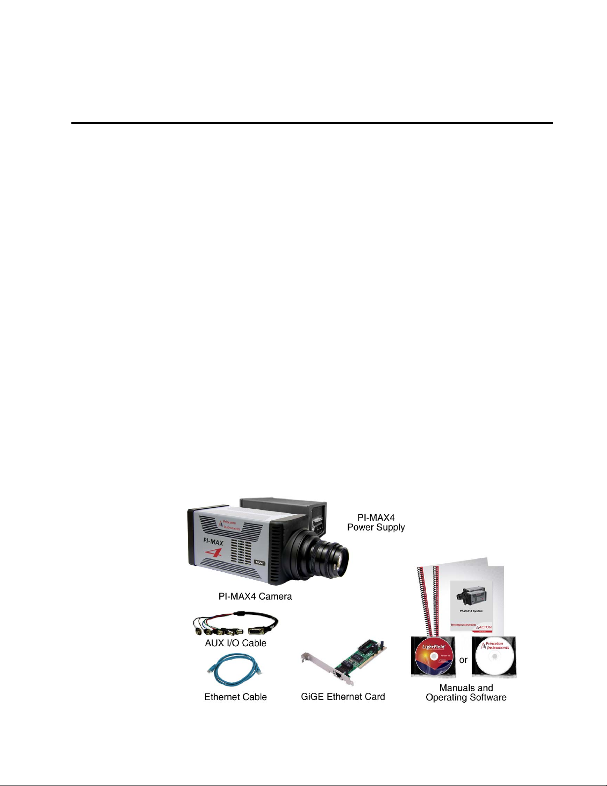
All PI-MAX4 systems consist of standard hardware and software as well as the appropriate
interface hardware for your computer system. Figure 1-1 illustrates the set of typical system
components included with all PI-MAX4 systems.
Figure 1-1: Typical PI-MAX4 System Components
19

20 PI-MAX® 4 System Manual Issue 4
The following items are standard with all PI-MAX4 systems:
•Camera
The PI-MAX4 camera houses the CCD and intensifier and it supplies all of the high
voltages needed to operate the intensifier (refer to Chapter 3, System Setup, for
more information.)
Cooling within the camera is performed by a cooling fan and a multi-stage Peltier
cooler that is thermally coupled to the CCD (liquid coolant circulation can also be
used for the PI-MAX4 camera.) Photocathode cooling to reduce equivalent
background illumination (EBI) can be achieved via a chilled dry nitrogen source.
C-, F-, and Spectroscopy-mount adapters are supplied (one of which is
factory-installed.)
The camera can be operated in one of the following two modes:
— Safe Mode
In Safe mode, the photocathode is gated off.
— Gate Mode.
In Gate mode, the photocathode is biased on only during the time each gate
pulse is applied.
The PI-MAX4 contains the analog and digital electronics, scan control and
exposure timing hardware, and controller I/O connectors. Readout modes supported
include full resolution, simultaneous multiple sub-images, and non-uniform
binning. Single or multiple software-defined regions of interest can also be tested
without having to digitize all the pixels of the array. Flexible exposure, set through
software, is also fully supported.
The PI-MAX4 contains two High Speed analog-to-digital converters. The effective
digitization rate is software-selectable. After the data is converted, it is transferred
directly from the camera to the host computer memory via the high speed interface
cable.
•Cable
AUX I/O Cable: 6050-0660, female DB26 to 5 BNC.
• Computer Interface
Standard Ethernet Cable: 6050-0621, 5 meter. Other lengths up to 100 m are
available.
User-provided GigE interface card. (Intel Pro1000 recommended)
• Tubing
Clear PVC tubing, 3’, 5/32” OD, 1/32” wall (McMaster-Carr 5006K42) for dry
nitrogen cooling of photocathode.
• Manuals
PI-MAX4 System manual and optional application software manual.
• Optional Application Software
Princeton Instruments' WinView/32 or WinSpec/32.
—
— Princeton Instruments’ LightField.
Chapter 1 Introduction 21
Electr
Intensifier Gated On
Input Window
CCD Array
Fiberoptic Bundle
on Flow
Input Window
-200 V
0 V
600 V - 900 V
6 kV
Electrical Connection Rings
Photocathode
Microchannel Plate (MCP)
: - +
Incident Light
Phosphor (Fluorescent Screen)
4411-0137_0001
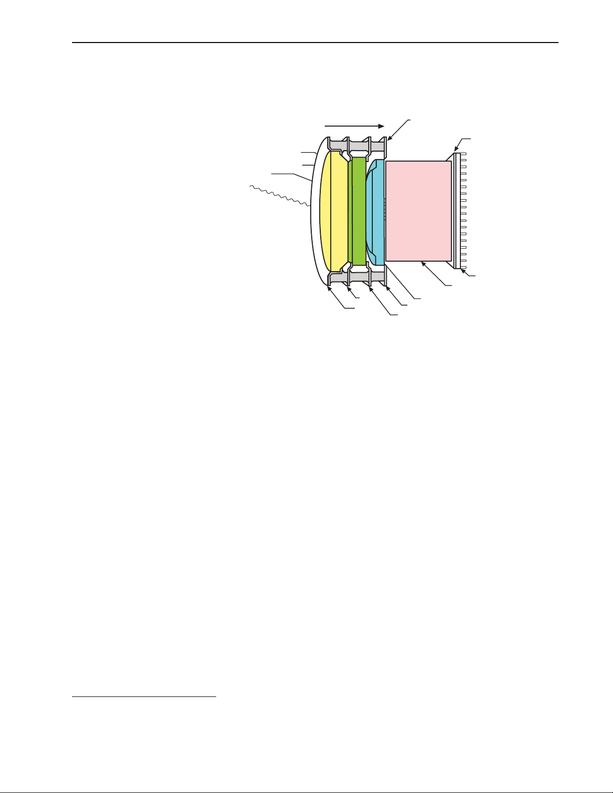
1.2 Summary of PI-MAX4 Data Acquisition
Figure 1-2 illustrates the major components that comprise an Intensifier-CCD.
Figure 1-2: Major Components of the Intensifier-CCD
In the PI-MAX4 camera, the input image is focused onto the photocathode of an image
intensifier tube. The tube electronically amplifies the image and outputs it, much brighter, as
gray-scaled green light. That light is then coupled to the CCD using a fused fiber-optic bundle
from the output of the image intensifier to the front side of the CCD. The image at the output
1
of the image intensifier is translated to the input of the CCD at the same size.
After being
detected by the CCD, the image is read out to the internal controller, where it is digitized, and
then transferred to the computer for processing via a high-speed data link.
The sequence below steps through the process by which photons are converted to data that
can be displayed on a computer monitor. For the sake of simplicity, triggers and gate pulses
are not mentioned and it is assumed that a high speed (GigE) serial interface card is installed
in the host computer. When reading through the sequence, keep in mind that electrons are
attracted to more positively charged surfaces and are repelled by more negatively charged
surfaces. This principal is used to control electron flow through the intensifier tube:
changing the photocathode voltage with respect to the voltage at the MCP input is used to
switch (gate) the intensifier on and off.
1. Incident photons pass through the intensifier input window, strike the photocathode, and
release electrons. See Figure 1-2.
2. Assuming that the intensifier is gated ON (the photocathode is more negative than the
MCP input,) these electrons will be attracted to the MCP input.
shutter in that gating the intensifier on allows the CCD to see light and gating the
intensifier off prevents the CCD from seeing light.
Since the voltage at the MCP output is much more positive, most of the electrons
3.
Gating acts like a
accelerate into the MCP channels and, if they hit the channel walls, will generate
additional electrons, resulting in electron gain.
increasing or decreasing the voltage at the MCP output.
The amount of gain is adjusted by
1. Units having a tapered fiber optic bundle may also be available. Contact the factory for information.

22 PI-MAX® 4 System Manual Issue 4
CAUTION!
!
WARNING! RISK OF ELECTRIC SHOCK!
4. When the electrons exit the channels they are further accelerated by a constant high
voltage (5-6 kV) and strike the phosphor coating on the fluorescent screen causing it to
release photons.
photon that struck the photocathode surface.
5.
The photons released by the coating are transferred to the surface of the CCD (via
Because of the MCP gain, there are now many photons for each
fiber-optic) and produce charge at the pixels they strike. Note that fiber-optic coupling
is not only the most efficient coupling possible, but lens-coupling effects such as
vignetting are eliminated.
6. Charge accumulates in the pixel wells until the intensifier is gated off (the photocathode
is more positive than the MCP input) and the phosphor decays.
7. At that point, the accumulated charge is shifted to the serial register where it is read out
to an on-chip amplifier that converts the charge to an analog voltage.
8. This voltage is input to the selected analog-to-digital (A/D) converter(s) where it is
digitally encoded. The conversion speed and the quality of the data are dependent on the
effective ADC rate.
9. The digitized information is transmitted from the camera through the Ethernet cable to
the interface card in the host computer where it is stored in RAM.
10. The application software retrieves the information from RAM, processes it, displays it,
and/or stores it to a file according to user-defined settings.
1.3 Safety Related Symbols Used in This Manual
The use of this symbol on equipment indicates that one or more
nearby items should not be operated without first consulting
the manual. The same symbol appears in the manual adjacent
to the text that discusses the hardware item(s) in question.
The use of this symbol on equipment indicates that one or more
nearby items pose an electric shock hazard and should be
regarded as potentially dangerous. This same symbol appears
in the manual adjacent to the text that discusses the hardware
item(s) in question.

Chapter 1 Introduction 23
WARNINGS!
WARNING! RISK OF ELECTRIC SHOCK!
WARNING!
1.4 Grounding and Safety
The PI-MAX4 and power supply are of Class I category as defined in IEC Publication 348
(Safety Requirements for Electronic Measuring Apparatus.) They are designed for indoor
operation only. Before turning on the power supply, the ground prong of the power cord
plug must be properly connected to the ground connector of the wall outlet. The wall outlet
must have a third prong, or must be properly connected to an adapter that complies with
these safety requirements.
1. If the PI-MAX4 camera system is used in a manner not specified
by Princeton Instruments, the protection provided by the
equipment may be impaired.
2. If the equipment is damaged, the protective grounding could be
disconnected. Do not use damaged equipment until its safety has
been verified by authorized personnel. tampering with its
operation is also prohibited.
Inspect the supplied power cord. If it is not compatible with the power socket, replace the
cord with one that has suitable connectors on both ends.
The PI-MAX4 has internal power supplies that generate
hazardous (and potentially lethal) voltages. It contains no
user-serviceable parts. Do not attempt to operate it with the
covers removed.
Replacement power cords or power plugs must have the same
polarity and power rating as that of the original ones to avoid hazard
due to electrical shock.

24 PI-MAX® 4 System Manual Issue 4
NOTE:
NOTE:
CAUTION!
!
1.4.1 Intensifier Modes and Safety
WinX Applications
The Experiment Setup
intensifier modes:
only for the time that each gate pulse is applied. As a result, the tolerance to room light is
higher in gated operation, but the risk of damaging overload from intense light sources such
as lasers remains. In fact, intense light sources in gated experiments can cause spot damage
that would be undetected by the alarm circuit. In
continuously biased OFF and the intensifier is as safe as it can be.
LightField
In LightField, you can enable or disable the intensifier on the
Settings
the photocathode is continuously biased OFF and the intensifier is as safe as it can be.
expander. When the intensifier is enabled, the camera can be gated; when disabled,
In order for gating to occur, the I.I.T. switch on the back of the
PI-MAX4 must also be in the ON position.
Main screen in WinX applications allows you to select one of two
Gate Mode or Safe Mode. In Gate Mode, the photocathode is biased on
Safe Mode, the photocathode is
Common Acquisition
1.4.2 Audible Alarm
To reduce the risk of camera damage, the PI-MAX4 camera is equipped with an audible
alarm in the camera, activated when the intensity of light falling on the image intensifier
exceeds a preset threshold. While the alarm is sounding, the photocathode is disabled.
Immediately switch the
the camera window and only switch the
been lowered. If the alarm sounds continuously even when the illumination level is
adequately low, shut the system down and contact the factory for guidance.
It is normal for the alarm to sound briefly when the system is
initially turned on.
I.I.T. switch on the back of the PI-MAX4 to the OFF position. Cover
I.I.T. switch to ON after the illumination level has
Discontinue operation and contact the factory at once if
sporadic or continuous unwarranted alarms occur. They may
indicate intensifier damage or another situation that requires
immediate attention.

Chapter 1 Introduction 25
WARNING!
1.4.3 High Intensity Light Damage
When biased ON, intensified CCD cameras, such as the PI-MAX®4
can be irreparably damaged if continuously exposed to light levels
higher than twice the A/D saturation level. Therefore, it is
that conditions
not be created which could result in damage to the
intensifier. Although intensified cameras are less prone to damage
from
background light when operated in gated mode, they are at
significant risk to damage from high-intensity light sources such as
a laser. High-intensity sources can damage the intensifier before
protection circuits have time to respond, or even cause spot damage
without the protection circuits acting at all. If a sustained alarm
indication occurs when the camera is turned on, immediately switch
the
I.I.T. switch on the back of the PI-MAX4 to the OFF position.
Cover the camera window and only switch the
I.I.T. switch to ON
after the illumination level has been lowered.
If the alarm sounds continuously even when the illumination level is adequately low, shut
the system down and contact the factory for guidance.
critical
1.5 Precautions
To prevent permanently damaging the system, please observe the following precautions:
• Always switch off and unplug the PI-MAX4 power supply before changing your
system configuration in any way.
• Whenever you turn the PI-MAX4 power supply OFF, be sure to leave it OFF for at
least 30 seconds before switching it back ON. If you switch it ON too soon, a fault
logic state is established that causes the overload alarm to sound continuously.
• The CCD array is very sensitive to static electricity. Touching the CCD can destroy
it. Operations requiring contact with the device can only be performed at the
factory.
• Never operate the camera cooled without proper evacuation or backfill. This could
damage the CCD! Do not open the purge valve.
• Never connect or disconnect any cable while the PI-MAX4 system is powered on.
Reconnecting a charged cable may damage the CCD.
• Never prevent the free flow of air through the equipment by blocking the air vents.

26 PI-MAX® 4 System Manual Issue 4
WARNING!
WARNING!
1.6 Cleaning and Maintenance
1.6.1 Cleaning the Camera
Although there is no periodic maintenance that must be performed on the PI-MAX4 camera,
users are advised to wipe it down with a clean dust collecting cloth from time to time.
1.6.2 Cleaning Optical Surfaces – Protective Window
Optical surfaces may need to be cleaned due to the accumulation of atmospheric dust. We
advise that the
tissue into clean anhydrous methanol, and then dragging the dampened tissue over the
optical surface to be cleaned. Do not allow any other material to touch the optical surfaces.
1.6.3 Flushing and Refilling the CCD Chamber
Under normal conditions the CCD chamber is sealed and backfilled
so there is no danger of damage due to condensation.
drag-wipe technique be used. This involves dipping a clean cellulose lens
Before a PI-MAX4 camera leaves the factory, its CCD chamber is backfilled with clean dry
air or dry nitrogen. For proper operation it is essential that the integrity of the front
enclosure be maintained.
In normal operation, the CCD chamber should remain sealed for the life of the camera and
should require no maintenance to assure integrity. If it should ever happen that the CCD
chamber becomes unsealed, contact the factory and arrange to return the camera to the
factory where it can be properly flushed, backfilled and resealed again. Refer to Contact
Information on page 312 for complete contact information.
1.7 Repairs
Save the original packing materials. Since the PI-MAX4 system contains no
user-serviceable parts, repairs must be done by Princeton Instruments. Should a system need
repair, contact Princeton Instruments customer support for instructions. Refer to Contact
Information on page 312 for complete contact information.
Use the original packing materials whenever shipping the system or system components.
Operating a PI-MAX4 that is no longer backfilled with dry air or dry
nitrogen may result in condensation on the array that could cause
irreversible damage. Such damage would not be covered by the
Warra nty.

Chapter 1 Introduction 27
NOTE:
1.8 About this Manual
This section provides information about the organization of this manual.
1.8.1 Conventions Used in this Manual
WinX is a generic term for WinView/32, WinSpec/32, and WinXTest application software.
In this manual,
Most features supported by the PI-MAX4 are also supported by the PI-MAX4-RF and
PI-MAX4: EM family. Therefore,
unless a distinction must be made between specific camera types.
In many instances, WinX and LightField use different terms for the same functions or
parameters. Unless the topic is specifically for LightField or WinX, curly brackets { } are used
to denote a LightField term or location. When the topic applies to both application programs,
the WinX term will be followed by the {LightField term}: for example, when
Cleans
is used, it will be followed by {Clean Until Trigger}. This convention is also used
when a location for setting a parameter is mentioned: for example, the desired camera
temperature is set on the
detector and camera are used interchangeably.
PI-MAX4 is used generically throughout this manual
The PI-MAX4-RF does not support picosecond gating or MCP
gating.
Continuous
Detector Temperature dialog {Sensor expander}.
1.8.2 Manual Organization
This manual provides the user with all the information needed to install a PI-MAX4
Intensified CCD camera and place it in operation. Topics covered include a detailed
description of the camera, installation and setup, first time data acquisition, tips and tricks,
microscopy applications, temperature control and more. A brief description of each chapter
and appendix is provided:
• Chapter 1, Introduction, provides an overview of the PI-MAX4 camera. Topics
include a description, theory of operation, and specifications.
• Chapter 2, System Installation, cross-references system setup actions with the
relevant manuals and/or manual pages. It also contains system layout diagrams.
• Chapter 3, System Setup, provides detailed directions for installing and setting up
the PI-MAX4 for both spectroscopy and imaging.
• Chapter 4, First Light, provides abbreviated directions for getting your PI-MAX4
into operation as soon as possible.
• Chapter 5, Gate Mode Operation, provides information about experiment setup,
temperature control, background subtraction, array readout, binning, and
digitization when operating in Gate Mode.
• Chapter 7, WinX and Gated Operation, discusses issues specific to using WinX and
operating the PI-MAX4 system in gate mode.
• Chapter 6, LightField and Gated Operation, discusses issues specific to using
LightField and operating the PI-MAX4 system in gate mode.
• Chapter 8, Timing Generator, discusses and illustrates the trigger modes available
when operating the system in gate mode.
• Chapter 10, WinX and Dual Image Feature, discusses using WinX with the mode
specifically designed for capturing a pair of gated images in rapid succession.

28 PI-MAX® 4 System Manual Issue 4
• Chapter 9, LightField and Dual Image Feature, discusses using LightField with the
mode specifically designed for capturing a pair of gated images in rapid succession.
• Chapter 11, MCP Gating Option, discusses how to set up a PI-MAX4 that has an
installed MCP Gating board.
• Chapter 12, Picosecond Gating Option, discusses how to set up a PI-MAX4 that has
an installed Picosecond board.
• Chapter 13, PI-MAX4: 1024i-RF and RF Modulation, discusses how to set up a
PI-MAX4: 1024i-RF camera for RF modulation.
• Chapter 14, PI-MAX4: EM Family, discusses emICCD cameras, Electron
Multiplication, and the use of Kinetics.
• Chapter 15, Tips and Tricks, discusses a number of issues that can have a bearing on
getting good experimental results.
• Chapter 16, Component Descriptions, describes the PI-MAX4 camera and other
system components. Includes descriptions of connectors and other front and rear
panel features.
• Chapter 17, Troubleshooting, provides information regarding possible system
problems.
• Appendix A, Technical Specifications, provides general specifications as well as
operating environment and internal pulser specifications.
• Appendix B, Outline Drawings, includes outline drawings for the PI-MAX4
camera, the PI-MAX4 power supply, and the CoolCUBE
• Appendix C, WinX/LightField Cross Reference, includes two alphabetically sorted
coolant circulator.
II
tables (WinX to LightField and LightField to WinX) that cross reference terms used
in the two applications.
• Appendix D, Extender Bracket Kit, explains how to use this kit to mount the
PI-MAX4 to any laboratory table with either 25 mm or 1 inch hole spacing.
• Appendix E, C- and F-Mount Information, discusses focusing of an F-mount
adapter and focusing of F-mount and C-mount lenses.
• Appendix F, Spectrograph Mount Information, provides instructions for the
mounting a PI-MAX4 camera with a spectroscopy adapter to an Acton SpectraPro
Series or IsoPlane spectrograph. Additional instructions describe how to perform
rotational alignment and focusing of the camera to the spectrograph optics.
• Appendix G, Accessories, provides information about available adapter kits and
accessories, include procedures for changing the adapter on the front of the
PI-MAX4 to another type when multiple adapters are available.
• Appendix H, Glossary, provides definitions of commonly used words and terms
related to intensified camera characteristics and usage.
• Declaration of Conformity contains the Declarations of Conformity for PI-MAX4
systems.
• Warranty & Service details the warranties for Princeton Instruments equipment and
software.

Chapter 2: System Installation
Table 2-1 describes the sequence of actions required to install a PI-MAX4 system and
prepare to gather data. Where available, refer to the references specified with each step to
obtain additional information.
Table 2-1: PI-MAX4 System Installation Procedure (Sheet 1 of 2)
Action
1. If the system components have not already been unpacked, unpack
them and inspect their carton(s) and the system components for in
For additional information, refer
to…
Chapter 3, System Setup, on
page 33
transit damage.
2. Verify that all system components have been received. Chapter 3, System Setup, on
page 33
3. If the camera will be used on a spectrograph, mount it to the
equipment using the required adapter(s.)
Appendix F, Spectrograph
Mount Information, on
page 285
4. If the appropriate interface card is not already installed in the host
computer, install it and its drivers.
Section 3.6, Application
Software Installation, on
page 39
5. If the application software has not already been installed on the host
computer, install it.
WinView User Manual,
document number 4411-0046
WinSpec User Manual,
document number 4411-0048
LightField User Manual,
document number 4411-0125
6. With the PI-MAX4 power supply and computer power turned OFF,
connect the Ethernet cable (GigE) to the PI-MAX4 and the interface
card in the host computer.
7. Make the following connections based upon the type of system being
setup:
• Air-Cooled System
Plug the power supply into the rear of the camera and plug the
power supply into the power source.
• Liquid-Cooled System
Make the hose and power connections to the camera and plug the
circulator into the power source. Add coolant if necessary. Turn
on the circulator.
Section 3.7, Connect the
Circulator [Liquid-Cooled
Cameras Only], on page 42.
29

30 PI-MAX® 4 System Manual Issue 4
Table 2-1: PI-MAX4 System Installation Procedure (Sheet 2 of 2)
Action
8. If the photocathode will be cooled, connect the supplied PVC tubing
to the hose barb on the front of the camera and to a
chilled dry
nitrogen source.
9. Turn the PI-MAX4 power supply ON.
10. Turn on the computer and launch either LightField or WinX.
When the computer boots, it may prompt for the location of interface
drivers.
• LightField
When LightField launches, it will detect the camera and
automatically place its icon in the
When you move that icon to the
Available Devices area.
Experiment Devices area, the
default parameters will automatically be loaded into the
expanders.
• WinX
If this is the first time using a WinX application, the Camera
Detection wizard will automatically run. This wizard retrieves
information from the camera and enters this information as the
default parameters for the system.
For additional information, refer
to…
Section 3.8, Configure Default
Camera System Parameters, on
page 44
LightField Users Manual (PDF)
This is available in the
Documents subdirectory of the
location where LightField was
installed.
WinView User Manual,
document number 4411-0046
WinSpec User Manual,
document number 4411-0048
11. Verify the hardware setup information and, if necessary, edit the
parameters. Enter the pulser information. Enter the experiment setup
parameters. If using a spectrograph, enter or edit that setup
information
12. Set the target array temperature. The typical target temperature is
-25°C.
13. When the system reaches temperature lock, begin acquiring data in
focus mode.
14. Adjust the focus for the best image or spectral lines.
• When using LightField, use the Align Spectrometer function.
• When using WinSpec/32, use the Focus Helper function.
LightField User Manual,
document number 4411-0125
WinView User Manual,
document number 4411-0046
WinSpec User Manual,
document number 4411-0048
Section 5.5.3, Setting the
Temperature, on page 67
Section 4.6.4, Initial Data
Acquisition, on page 59.
Appendix E, C- and F-Mount
Information, on page 281;
Appendix F, Spectrograph
Mount Information, on
page 285.
 Loading...