


4411-0106
Version 2.C
July 2, 2013
*4411-0106*

Copyright 2004-2013 Princeton Instruments, a division of Roper Scientific, Inc.
3660 Quakerbridge Rd
Trenton, NJ 08619
TEL: 800-874-9789 / 609-587-9797
FAX: 609-587-1970
All rights reserved. No part of this publication may be reproduced by any means without the written
permission of Princeton Instruments, a division of Roper Scientific, Inc. ("Princeton Instruments").
Printed in the United States of America.
IntelliCal and PICam are trademarks and eXcelon, LightField, and PVCAM are registered trademarks of
Roper Scientific, Inc.
LabVIEW is a registered trademark of National Instruments, Inc.
LEMO is a registered trademark of INTERLEMO HOLDING SA
Nikon is a registered trademark of Nikon, Inc.
Scientific Imaging ToolKit and SITK are trademarks of R Cubed Software Consultants, LLC.
SpectraPro is a trademark of Acton Research Corporation.
Windows and Windows Vista are registered trademarks of Microsoft Corporation in the United States
and/or other countries.
The information in this publication is believed to be accurate as of the publication release date. However,
Princeton Instruments does not assume any responsibility for any consequences including any damages
resulting from the use thereof. The information contained herein is subject to change without notice.
Revision of this publication may be issued to incorporate such change.

Table of Contents
Chapter 1 Introduction .........................................................................................9
PIXIS .................................................................................................................................. 9
eXcelon® ............................................................................................................................. 9
Advanced Design ................................................................................................................ 9
Grounding and Safety ....................................................................................................... 10
Precautions ........................................................................................................................ 10
UV Coating ....................................................................................................................... 10
Cleaning ............................................................................................................................ 11
Repairs .............................................................................................................................. 11
About this Manual ............................................................................................................ 11
Chapter 2 System Component Descriptions .................................................. 13
System Components ......................................................................................................... 13
PIXIS Camera ................................................................................................................... 14
Power Supply (Air-cooled and CoolCUBE
Coolant Hoses (Liquid-cooled systems) ........................................................................... 15
Cables ............................................................................................................................... 16
Certificate of Performance ................................................................................................ 16
User Manuals .................................................................................................................... 16
Optional Components ....................................................................................................... 17
Chapter 3 Initial System Verification ............................................................... 19
Liquid-cooled systems) ................................... 15
II
Chapter 4 System Setup ................................................................................... 23
Introduction ....................................................................................................................... 23
Unpacking the System ...................................................................................................... 23
Checking the Equipment and Parts Inventory................................................................... 24
System Requirements ....................................................................................................... 24
Software Installation ......................................................................................................... 26
Making the Camera-Circulator Connections for a CoolCUBEII ....................................... 27
Entering the Default Camera System Parameters ............................................................. 29
Attaching Lenses to C- and F-Mount Adapters ................................................................ 30
Mounting the Adjustable C- to Spectroscopy-Mount Kinetics Adapter ........................... 31
Mounting the Camera to a Spectrograph .......................................................................... 32
Connecting an External Shutter ........................................................................................ 33
Chapter 5 Operation .......................................................................................... 35
Introduction ....................................................................................................................... 35
System On/Off Sequences ................................................................................................ 36
WinX First Light Instructions ........................................................................................... 36
LightField First Light Instructions .................................................................................... 45
Exposure and Signal ......................................................................................................... 56
Readout ............................................................................................................................. 59
Digitization (Rate) ............................................................................................................ 65
iii

iv PIXIS System Manual Version 2.C
Chapter 6 Advanced Topics ............................................................................. 67
Introduction ....................................................................................................................... 67
Timing Modes ................................................................................................................... 68
Fast and Safe Modes ......................................................................................................... 74
LOGIC OUT Control ........................................................................................................ 76
Kinetics Mode ................................................................................................................... 77
Custom Modes .................................................................................................................. 80
Chapter 7 Troubleshooting .............................................................................. 83
Introduction ....................................................................................................................... 83
Acquisition Started but Viewer Contents Do Not Update ................................................ 84
Baseline Signal Suddenly Changes ................................................................................... 84
Camera Stops Working ..................................................................................................... 84
Camera1 (or similar name) in Camera Name field ........................................................... 85
Controller Is Not Responding ........................................................................................... 86
CoolCUBEII: Low Coolant (Air in the Hoses) .................................................................. 86
Cooling Troubleshooting .................................................................................................. 87
Data Loss or Serial Violation ............................................................................................ 88
Data Overrun Due to Hardware Conflict message ............................................................ 88
Data Overrun Has Occurred message ............................................................................... 89
Device Is Not Found ......................................................................................................... 89
Device is Occupied ........................................................................................................... 90
Error Creating Controller message ................................................................................... 90
Overexposed or Smeared Images ...................................................................................... 90
Program Error message ..................................................................................................... 91
Serial violations have occurred. Check interface cable. ................................................... 92
Shutter Failure ................................................................................................................... 92
Appendix A Basic Specifications .................................................................... 93
Window ............................................................................................................................. 93
CCD Arrays ...................................................................................................................... 93
Mounts .............................................................................................................................. 93
Focal Distance (Optical) ................................................................................................... 93
Shutter ............................................................................................................................... 94
Camera .............................................................................................................................. 94
CoolCUBEII Circulator with PIXIS-compatible Hoses (PN 7567-0002) ................................ 96
Options .............................................................................................................................. 96
Appendix B Outline Drawings .......................................................................... 97
PIXIS Camera: C-mount (Air-Cooled) ............................................................................. 97
PIXIS Camera: C-mount (Liquid-Cooled) ........................................................................ 99
PIXIS Camera: F-mount (Air-Cooled) ........................................................................... 101
PIXIS Camera: F-mount (Liquid-Cooled) ...................................................................... 102
PIXIS Camera: 2048 F-mount (Air-Cooled) .................................................................. 103
PIXIS Camera: 2048 F-mount (Liquid-Cooled) ............................................................. 104
PIXIS Camera: Spectroscopy mount (Air-Cooled) ........................................................ 105
PIXIS Camera: Spectroscopy mount (Liquid-Cooled) ................................................... 106
CoolCUBEII Circulator ................................................................................................... 108

Table of Contents v
Appendix C Adapter Adjustment and Focusing Procedures ...................... 109
Adjustable C-Mount Adapter .......................................................................................... 109
F-Mount Adapter Focusing Procedure ............................................................................ 110
Lens Focusing Procedure ................................................................................................ 111
Appendix D Spectrograph Adapters ............................................................. 113
Acton Series Spectrograph (PIXIS with Flange) ............................................................ 114
Acton Series Spectrograph (PIXIS with 3.60/3.88 Bolt Circles) .................................... 115
Acton Series Spectrograph (PIXIS with C-Mount) ........................................................ 116
Acton SP-2350/SP-2550 Adjustable C- to Spectroscopy-Mount Adapter (Adapter
Kit 7050-0104) ......................................................................................................... 117
Acton SP-2150/SP-2750 Adjustable C- to Spectroscopy-Mount Adapter (Adapter
Kit 7050-0107) ......................................................................................................... 118
IsoPlane SCT-320 (PIXIS with Flange) ......................................................................... 119
Appendix E Cross-Referencing of WinX and LightField Terms .................... 121
WinX-to-LightField ........................................................................................................ 121
LightField-to-WinX ........................................................................................................ 123
Declaration of Conformity .............................................................................. 125
Warranty & Service ......................................................................................... 129
Limited Warranty ............................................................................................................ 129
Contact Information ........................................................................................................ 132
Index ................................................................................................................. 133
Figures
Figure 1. Typical System Components ............................................................................ 13
Figure 2. Typical Imaging Experiment Layout (Air-cooled Camera) ............................. 20
Figure 3. Typical Spectroscopy Experiment Layout (Air-cooled Camera) ..................... 20
Figure 4. Typical Imaging Experiment Layout (Liquid-cooled Camera with
CoolCUBEII) ................................................................................................. 21
Figure 5. Typical Spectroscopy Experiment Layout (Liquid-cooled Camera with
CoolCUBEII) ................................................................................................. 21
Figure 6. WinView Installation: Select Installation Type dialog..................................... 26
Figure 7. LightField Installation Wizard dialog .............................................................. 27
Figure 8. Camera Detection Wizard - Welcome dialog ................................................... 29
Figure 9. LightField Experiment Workspace................................................................... 30
Figure 10. Adjustable C- to Spectroscopy-Mount Kinetics Adapter ............................... 32
Figure 11. Acton Series Spectrograph Entrance Slit Mount ............................................ 33
Figure 12. Block Diagram of PIXIS System .................................................................. 35
Figure 13. Available Devices Area .................................................................................. 45
Figure 14. Experiment Devices Area ............................................................................... 46
Figure 15. View Area....................................................................................................... 47
Figure 16. View Area Displaying an Image .................................................................... 47
Figure 17. Available Devices Area .................................................................................. 49
Figure 18. Experiment Devices Area ............................................................................... 50
Figure 19. View Area....................................................................................................... 52
Figure 20. Spectrometer Alignment: Before Rotational Alignment ................................ 53
Figure 21. Spectrometer Alignment: After Rotational Alignment .................................. 54
Figure 22. Exposure of the CCD with Shutter Compensation ......................................... 56

vi PIXIS System Manual Version 2.C
Figure 23. WinX Detector Temperature dialog .............................................................. 57
Figure 24. Array Terms for a CCD with a Dual Output Amplifier ................................ 59
Figure 25. Full Frame at Full Resolution ......................................................................... 60
Figure 26. 2 × 2 Binning .................................................................................................. 61
Figure 27. Binning and Array Orientation ....................................................................... 63
Figure 28. Free Run {No Response} Timing Chart, part of the chart in Figure 36 ......... 69
Figure 29. Free Run {No Response} Timing Diagram.................................................... 69
Figure 30. Chart Showing Two External Sync Timing Options ...................................... 70
Figure 31. Timing Diagram for External Sync Mode (+ edge trigger) ............................ 71
Figure 32. Continuous Cleans {Clean Until Trigger} Flowchart .................................... 72
Figure 33. WinX Continuous Cleans Timing Diagram ................................................... 73
Figure 34. LightField Clean Until Trigger (CUT) Timing Diagram ............................... 73
Figure 35. Rear of PIXIS Camera .................................................................................... 73
Figure 36. Chart of Safe and Fast Mode Operation ......................................................... 75
Figure 37. Comparison of NOT SCAN {Not Reading Out}, SHUTTER {Shutter
Open}, and NOT READY {Busy} Logic Output Levels .............................. 76
Figure 38. Kinetics Readout ............................................................................................ 77
Figure 39. Hardware Setup dialog ................................................................................... 78
Figure 40. Experiment Setup dialog ................................................................................ 78
Figure 41. Sensor Readout expander: Kinetics Readout Mode ...................................... 78
Figure 42. Shutter and Trigger expanders: No Response ............................................... 78
Figure 43. Free Run Timing Diagram.............................................................................. 79
Figure 44. Single Trigger Timing Diagram ..................................................................... 79
Figure 45. Multiple Trigger Timing Diagram.................................................................. 80
Figure 46. WinX: Custom Chip tab ................................................................................. 81
Figure 47. LightField: Custom Sensor pane .................................................................... 81
Figure 48. LightField: Custom Timing ............................................................................ 82
Figure 49. WinX: Vertical Shift ...................................................................................... 82
Figure 50. Acquisition Display ........................................................................................ 84
Figure 51. Camera1 in Camera Name Field .................................................................... 85
Figure 52. Data Overrun Due to Hardware Conflict dialog ............................................. 88
Figure 53. Devices Missing dialog .................................................................................. 89
Figure 54. Occupied Device icon .................................................................................... 90
Figure 55. Error Creating Controller dialog .................................................................... 90
Figure 56. Program Error dialog ...................................................................................... 91
Figure 57. Serial Violations Have Occurred dialog ......................................................... 92
Figure 58. Adjustable C-Mount: Internal Shutter (Air-cooled) ....................................... 97
Figure 59. Fixed C-Mount: Internal Shutter (Air-cooled) ............................................... 98
Figure 60. Adjustable C-Mount: Internal Shutter (Liquid-cooled) .................................. 99
Figure 61. Fixed C-Mount: Internal Shutter (Liquid-cooled) ........................................ 100
Figure 62. F-Mount: Internal Shutter (Air-cooled) ........................................................ 101
Figure 63. F-Mount: Internal Shutter (Liquid-cooled) .................................................. 102
Figure 64. F-Mount: 2048x2048, Internal Shutter (Air-cooled) .................................... 103
Figure 65. F-Mount: 2048x2048, Internal Shutter (Liquid-cooled) ............................... 104
Figure 66. Spectroscopy-Mount: No Internal Shutter, 3.60 bolt circle (Air-cooled) ..... 105
Figure 67. Spectroscopy-Mount: No Internal Shutter, 3.60 bolt circle (Liquid-cooled) 106
Figure 68. Spectroscopy-Mount: Internal Shutter (3.60" and 3.88" bolt circles)
(Air-cooled) ................................................................................................ 107
Figure 69. CoolCUBEII Circulator ................................................................................. 108
Figure 70. F-mount Adjustment ..................................................................................... 110

Table of Contents vii
Tables
Table 1. USB Driver Files and Locations ........................................................................ 26
Table 2. Example of Controller Gain {Analog Gain} vs. Readout Port .......................... 64
Table 3. Camera Timing Modes ...................................................................................... 68
Table 4. Focal Plane Distances ........................................................................................ 93
Table 5. Typical Deepest Operating Temperature ........................................................... 95

viii PIXIS System Manual Version 2.C
This page intentionally left blank.
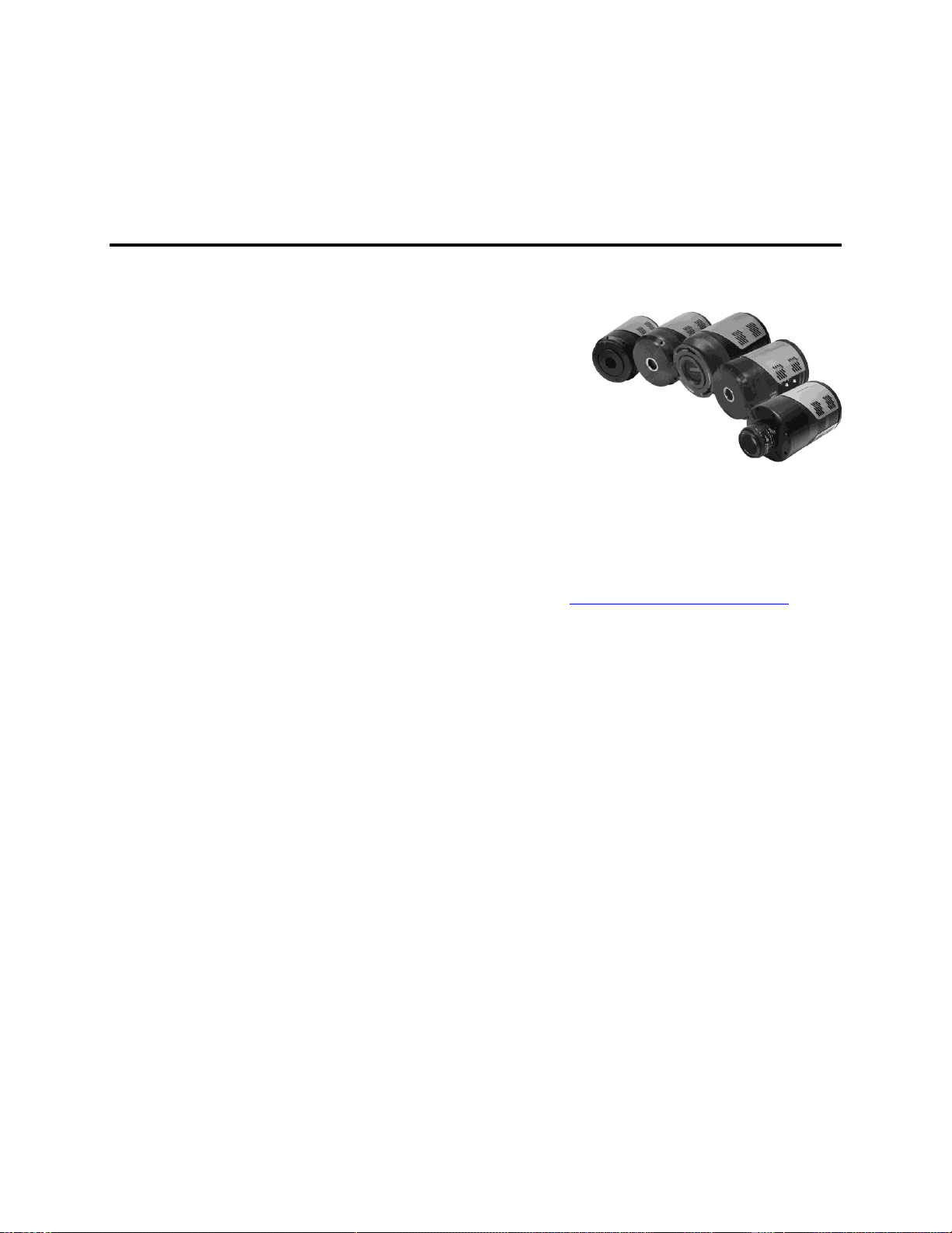
Chapter 1 Introduction
PIXIS
Thank you for purchasing a PIXIS camera system
from Princeton Instruments. For over two decades
Princeton Instruments has been the legendary name
behind the most revolutionary spectroscopy and
imaging products for cutting edge research.
PIXIS represents the most advanced camera design and utilizes years
of experience and expertise in low-light detection. Whether your
application involves Raman spectroscopy in the near infrared or
semiconductor imaging in the ultraviolet, PIXIS has everything you need to tackle the
most demanding applications.
Among the many state of the art features are its maintenance-free permanent vacuum,
integrated controller, deep thermoelectric air-cooling, and compact design. Currently the
platform supports several imaging and spectroscopy CCDs, including eXcelon® enabled
back-illuminated spectroscopy CCDs. Please visit www.princetoninstruments.com for the
current list of supported CCDs.
eXcelon
®
eXcelon is a new CCD/EMCCD sensor technology jointly developed by Princeton
Instruments, e2v, and Photometrics. Spectroscopy CCDs using this technology provide
three significant benefits:
Improved sensitivity – improved QE over broader wavelength region compared
to back-illuminated sensors,
Reduced etaloning – up to 10 times lower etaloning or unwanted fringes in near
infrared (NIR) region compared to standard back-illuminated CCDs,
Lower dark current – similar to back-illuminated CCDs or 100 times lower
than the deep depletion CCDs.
Advanced Design
PIXIS is a fully integrated camera system. The camera contains all of the electronics
necessary to read out and control the CCD device. For instance, it houses precision analogto-digital converters (ADCs) positioned close to the CCD for lowest noise and has USB 2.0
electronics to interface with the host computer.
The easy-to-use PIXIS camera system offers all basic CCD camera functions such as
region-of-interest (ROI) selection and binning --- all under software control. It also
provides advanced triggered operation as well as programmable TTL output.
To utilize the full potential of the PIXIS camera system, please read the manual completely.
9

10 PIXIS System Manual Version 2.C
WARNING!
WARNING!
Caution
Grounding and Safety
Before turning on the power supply (air-cooled system or liquid-cooled system with a
CoolCUBEII circulator), the ground prong of the power cord plug must be properly
connected to the ground connector of the wall outlet. The wall outlet must have a third
prong, or must be properly connected to an adapter that complies with these safety
requirements.
If the equipment is damaged, the protective grounding could be disconnected. Do not use
damaged equipment until its safety has been verified by authorized personnel.
Disconnecting the protective earth terminal, inside or outside the apparatus, or any
tampering with its operation is also prohibited.
Inspect the supplied power cord. If it is not compatible with the power socket, replace the
cord with one that has suitable connectors on both ends.
Replacement power cords or power plugs must have the same polarity and power rating
as that of the original ones to avoid hazard due to electrical shock.
Precautions
To prevent permanently damaging the system, please observe the following precautions:
UV Coating
If you have a camera with a UV (Lumogen or Unichrome) coated CCD, protect it from
unnecessary exposure to UV radiation. This radiation slowly bleaches the coating,
reducing sensitivity.
The CCD array is very sensitive to static electricity. Touching the CCD can
destroy it. Operations requiring contact with the device can only be performed at
the factory.
If you are using high-voltage equipment (such as an arc lamp) with your camera
system, be sure to turn the camera power ON LAST and turn the camera power
OFF FIRST.
Use caution when triggering high-current switching devices (such as an arc lamp)
near your system. The CCD can be permanently damaged by transient voltage
spikes. If electrically noisy devices are present, an isolated, conditioned power
line or dedicated isolation transformer is highly recommended.
Do not block air vents on the camera. Preventing the free flow of air overheats
the camera and may damage it.
If the PIXIS camera system is used in a manner not specified by Princeton
Instruments, the protection provided by the equipment may be impaired.

Chapter 1 Introduction 11
WARNING!
Cleaning
Turn off all power to the equipment and secure all covers before cleaning the units.
Otherwise, damage to the equipment or injury to you could occur.
Camera
Although there is no periodic maintenance that needs to be performed on a PIXIS
camera, users are advised to wipe it down with a clean damp cloth from time to time.
This operation should only be done on the external surfaces and with all covers secured.
In dampening the cloth, use clean water only. No soap, solvents or abrasives should be
used. Not only are they not required, but they could damage the finish of the surfaces on
which they are used.
Optical Surfaces
As a good practice, the camera must be closed/capped off with the supplied dust cover or
lens cap when not in use. Should a need to clean the optical window arise due to the
accumulation of atmospheric dust, we advise that the drag-wipe technique be used. This
involves dipping a clean cellulose lens tissue into clean anhydrous methanol, and then
dragging the dampened tissue over the optical surface to be cleaned. Do not allow any
other material to touch the optical surfaces.
Repairs
Because the PIXIS camera system contains no user-serviceable parts, repairs must be
performed by Princeton Instruments. Should your system need repair, contact Princeton
Instruments customer support for instructions. For contact information, refer to page 132
of this manual.
Save the original packing materials and use them whenever shipping the system or
system components.
About this Manual
Manual Organization
This manual provides the user with all the information needed to install a PIXIS camera
and place it in operation. Topics covered include detailed description of the cameras in
the PIXIS family, installation, applications, cleaning, specifications and more.
Notes:
1. "WinX" is a generic term for WinView/32, WinSpec/32, and WinXTest application
software.
2. In many instances, WinX and LightField® use different terms for the same functions
or parameters. Unless the topic is specifically for WinX or LightField, curly brackets
{ } are used to denote a LightField term or location. When the topic applies to both
application programs, the WinX term will be followed by the {LightField term}: for
example, when Continuous Cleans is used, it will be followed by {Clean Until
Trigger}. This convention is also used when a location for setting a parameter is
mentioned: for example, Exposure Time is set on the Experiment Setup|Main tab
{Common Acquisition Settings expander}.

12 PIXIS System Manual Version 2.C
Caution! The use of this symbol on equipment indicates that one or
more nearby items should not be operated without first consulting the
manual. The same symbol appears in the manual adjacent to the text
that discusses the hardware item(s) in question.
Warning! Risk of electric shock! The use of this symbol on
equipment indicates that one or more nearby items pose an electric
shock hazard and should be regarded as potentially dangerous. This
same symbol appears in the manual adjacent to the text that discusses
the hardware item(s) in question.
Chapter 1, Introduction provides an overview of the PIXIS cameras.
Chapter 2, System Component Descriptions provides information about the
camera, interface card, cables and application software.
Chapter 3, Installation Overview cross-references system setup actions with the
relevant manuals and/or manual pages. It also contains system layout diagrams.
Chapter 4, System Setup provides detailed directions for setting up the camera
for imaging or spectroscopic applications and presents over-exposure protection
considerations.
Chapter 5, Operation includes a step-by-step procedure for verifying system
operation and discusses operational considerations associated with exposure,
readout, and digitization.
Chapter 6, Advanced Topics discusses standard timing {Trigger Response}
modes (Free Run {No Response}, External Sync {Readout Per Trigger}, and
Continuous Cleans {Clean Until Trigger}), Fast and Safe modes, Logic Output
control, and Kinetics mode.
Chapter 7, Troubleshooting provides courses of action to take if you should
have problems with your system.
Appendix A, Basic Specifications includes camera and CoolCUBE
II
specifications.
Appendix B, Outline Drawings includes outline drawings of C-mount and
Spectroscopy-mount cameras.
Appendix C, Adapter Adjustment and Focusing Procedures discusses
focusing of an F-mount adapter and focusing of F-mount and C-mount lenses.
Appendix D, Spectrograph Adapters provides mounting instructions for the
spectrograph adapters available for PIXIS cameras.
Appendix E, Cross-Referencing of WinX and LightField Terms includes
two alphabetically sorted tables (WinX to LightField and LightField to WinX)
that cross reference terms used in the two applications.
Declaration of Conformity contains the Declarations of Conformity for the Small
Format PIXIS System and the Large Format PIXIS System
Warranty & Service contains the warranty and customer support contact information.
Safety Related Symbols Used in this Manual
Chapter 2 System Component Descriptions
System Components
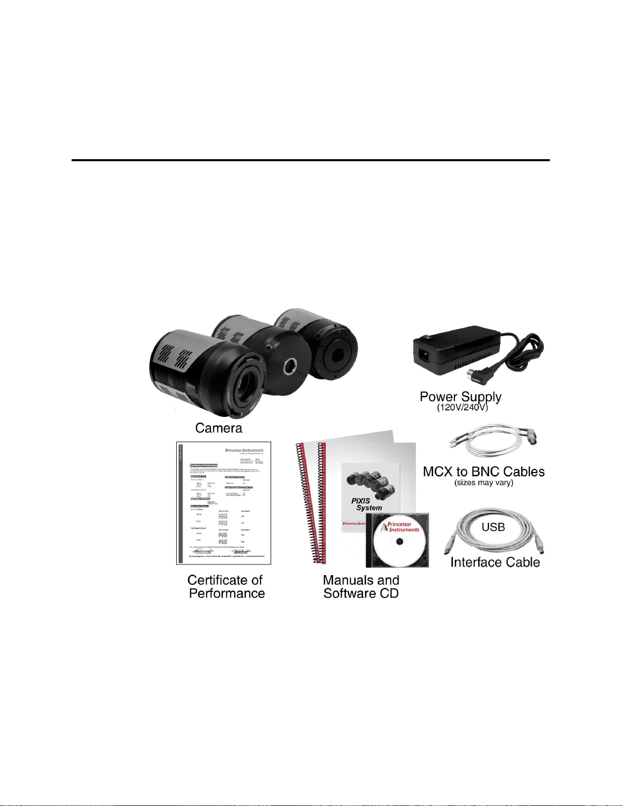
Standard Components
A typical air-cooled PIXIS system consists of the camera with a Certificate of
Performance, a power supply, a USB 2.0 interface cable for your computer system, MCX
to BNC adapter cables, and the user manual. A typical liquid-cooled PIXIS system
consists of the camera with a Certificate of Performance, a CoolCUBEII circulator with
hoses, a USB 2.0 interface cable for your computer system, MCX to BNC adapter cables,
and the user manual.
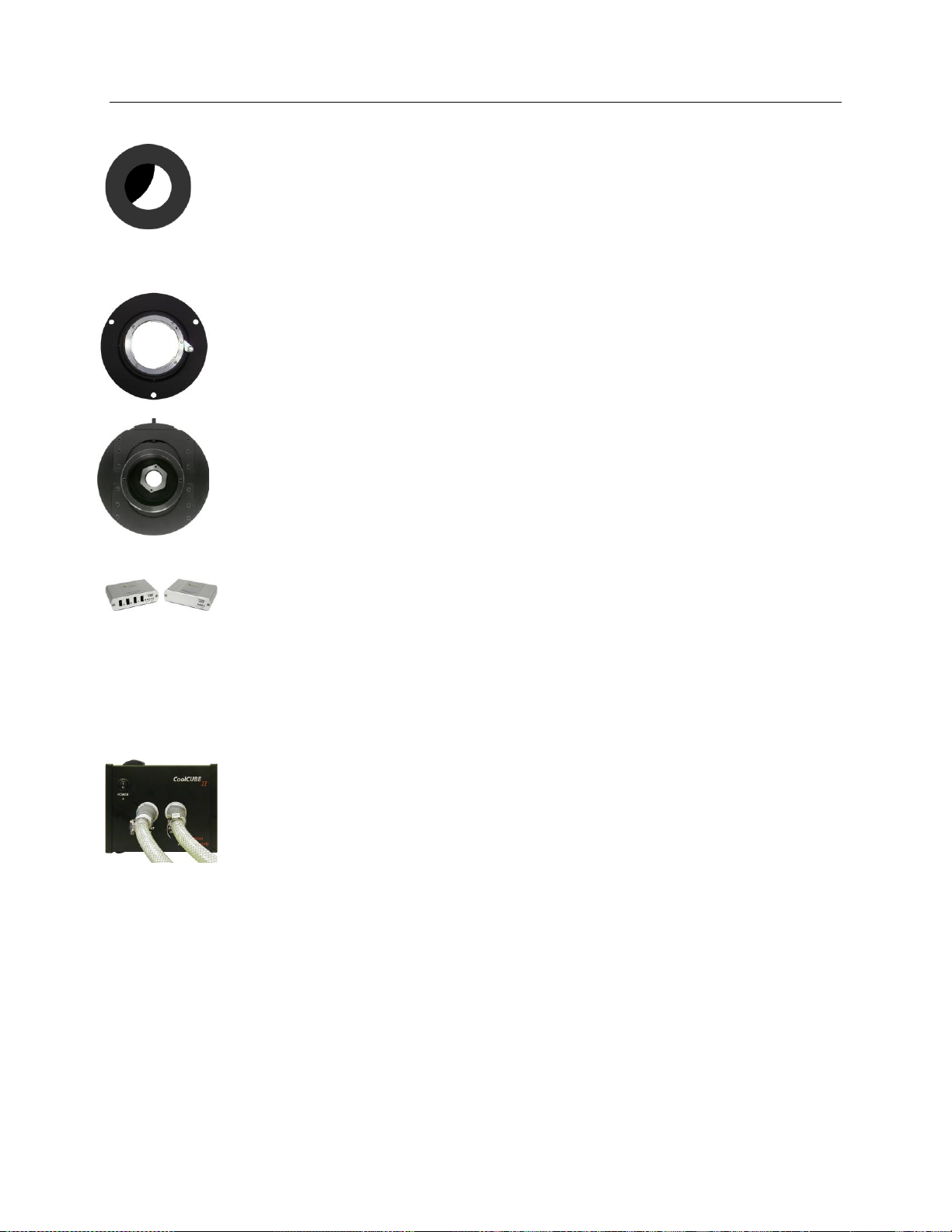
Figure 1. Typical System Components
Optional System Components
Optional items include the WinX application software and manual, LightField®
application software and manual, Scientific Imaging ToolKit™ (SITK™) for
LabVIEW®, internal 25 or 45 mm shutter (dependent on CCD array size), an F-mount
adapter, an adjustable C- to Spectroscopy-mount kinetics adapter, and a fiber optic
extender kit.
13

14 PIXIS System Manual Version 2.C
PIXIS Camera
CCD Array: The PIXIS camera system offers both front- and back-
illuminated CCDs in a variety of array sizes that allow you to precisely
match the sensor to your application. Only scientific-grade devices are
used in order to ensure the highest image fidelity, resolution, and
acquisition flexibility required for scientific imaging. Princeton Instruments has
developed exclusive CCDs with unmatched quantum efficiency and low noise to offer the
utmost in sensitivity. Large full wells, square pixels, and 100% fill factors provide high
dynamic range and excellent spatial resolution. Unichrome (exclusive Princeton
Instruments technology) and other UV-enhancement coatings can be used to further
improve the quantum efficiency of these CCDs in the ultraviolet. Your choice of CCD is
already installed in the camera that you received and has been individually tested.
Cooling: Dark current is reduced in PIXIS camera systems through thermoelectric
cooling of the CCD arrays. Cooling by this method uses a four-stage Peltier cooler in
combination with circulating air or coolant. To prevent condensation and contamination
from occurring, cameras cooled this way are evacuated. Due to CCD size/packaging
differences, the lowest achievable temperature can vary from one PIXIS model to the
next. Please refer to the specific system’s data sheet for cooling performance.
Connectors:
USB 2.0: Control signals and data are transmitted between
the camera and the host computer via the USB port located on
the rear of the camera. As of this printing, you can hot plug
the PIXIS camera whenever the WinX application is not
running (i.e., connect or disconnect from the camera or the
host computer while the camera is powered ON). In the
case of cameras built before November 1, 2005, you must
exit the WinX application and turn the camera power OFF
before connecting the USB cable to or disconnecting it from the camera or host
computer.
Shutter: LEMO
Instruments-supplied external shutter (for example, a shutter at the entrance slit of a
spectrograph). Camera power must be OFF before connecting to or disconnecting
from this connector.
Note: When there is an installed internal shutter, this connector cannot drive an
external shutter.
LOGIC OUT: 0 to +3.3V programmable logic level output (TTL-compatible). The
output of this connector can be programmed and can also be inverted via the
application software. For detailed information about each output signal, please see
“LOGIC OUT Control” (page 76).
EXT SYNC: 0-+3.3V logic level input (TTL-compatible) that has a 10 k pullup
resistor. Allows data acquisition and readout to be synchronized with external events.
Through software, positive or negative (default) edge triggering can be selected.
®
connector provides the shutter drive pulses for driving a Princeton
Power: 12 VDC (6.6A max) input from power supply.
Chapter 2 System Component Descriptions 15
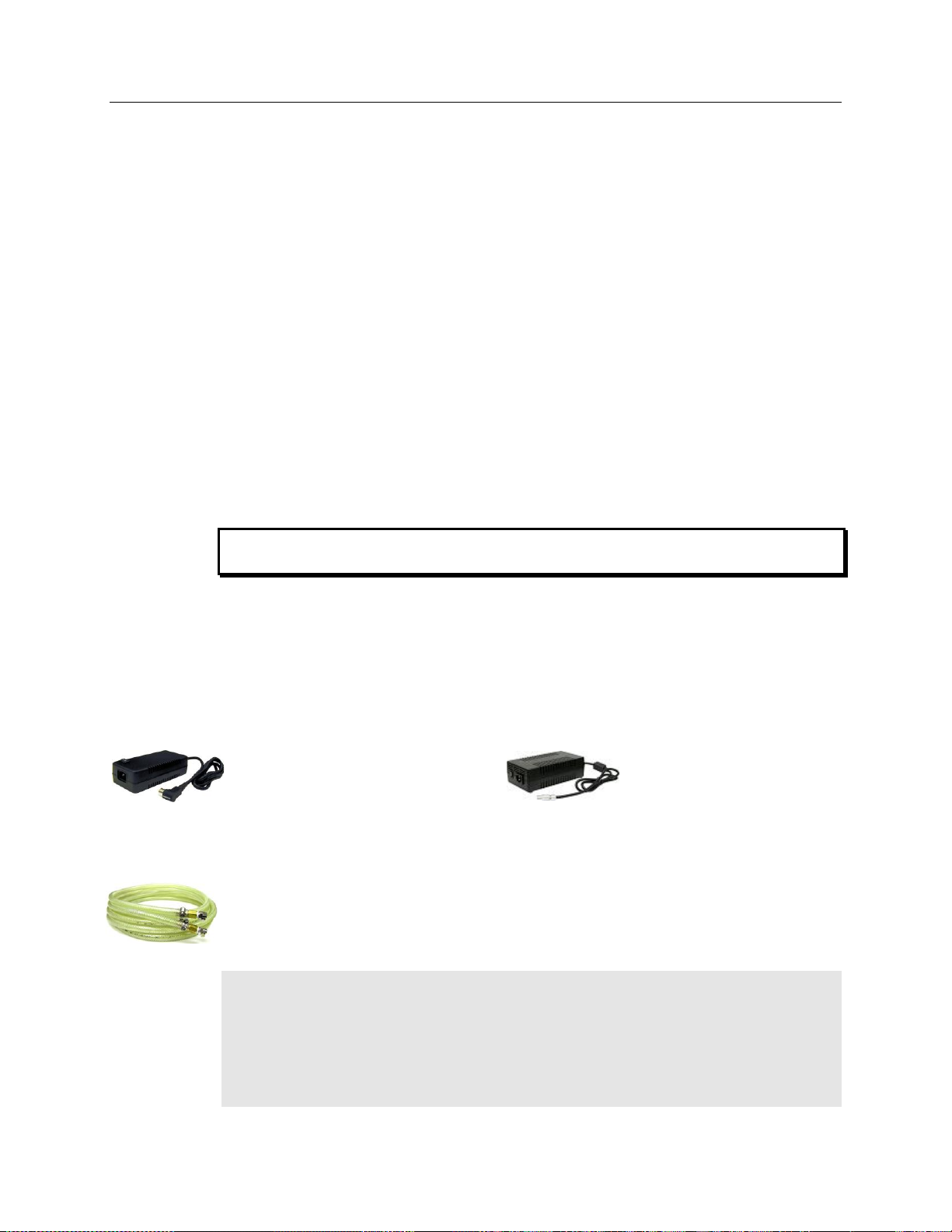
Small Format PIXIS
Maximum Power Output: 80 W
Input: 100-240 VAC, 47-63 Hz, 1.9A
Output: 12 VDC at 6.6 A maximum
Large Format PIXIS
Maximum Power Output: 150 W
Input: 100-240 VAC, 50/60 Hz, 2A
Output: 12 VDC at 12.5 A maximum
WARNING!
Fan: Air-cooled cameras contain an internal fan. Its purpose is:
to remove heat from the Peltier device that cools the CCD array and
to cool the electronics.
An internal Peltier device directly cools the cold finger on which the CCD is mounted.
The air drawn into the camera by the internal fan through the back slots on the side
panels and exhausted through the front slots on the side panels then removes the heat
produced by the Peltier device. The fan is always in operation and air-cooling of both
the Peltier and the internal electronics takes place continuously. The fan is designed
for low-vibration and does not adversely affect the image. For the fan to function
properly, free circulation must be maintained between the sides of the camera and the
laboratory atmosphere.
Coolant Ports: Liquid-cooled cameras have internal hoses that can be connected to the
CoolCUBEII circulator via the coolant ports on the side of the camera (either port can be
the input). As is the case with circulating air (see above), circulating coolant removes the
heat produced by the Peltier device. This means of heat removal is designed for
vibration-free data acquisition. For the circulating coolant to function properly, free air
circulation must be maintained between the sides of the CoolCUBEII and the laboratory
atmosphere.
Use only the hoses and circulator shipped with your system. Attaching any other hoses or
circulator voids the warranty.
Power Supply (Air-cooled and CoolCUBE
The receptacle on the power supply should be compatible with the line-voltage line cords in
common use in the region to which the system is shipped. If the power supply receptacle is
incompatible, a compatible adapter should be installed on the line cord, taking care to
maintain the proper polarity to protect the equipment and assure user safety.
Coolant Hoses (Liquid-cooled systems)
Quick-disconnects that mate to the PIXIS’s coolant ports have been installed on one end
of each hose. Refer to your coolant circulator’s specifications regarding circulator-
compatible hose fittings. If a Princeton Instruments CoolCUBEII circulator is ordered
with the camera, hoses are supplied with appropriate connectors on both ends.
Note: Part numbers for the hose, PIXIS fittings, and CoolCUBEII fitting are:
McMaster# MCM 5238K748 (3/8 ID, 5/8 OD tubing);
CPC# MCD1004 (1/4 NPT Valved Coupling Body) and McMaster# MCM 5346K35
(barbed hose fitting adapter for 3/8" hose ID X 1/4" NPTF female pipe) at PIXIS end;
and
CPC# NS6D17006 (3/8 hose barb valved in-line coupling body) at CoolCUBEII end.
Liquid-cooled systems)
II
16 PIXIS System Manual Version 2.C
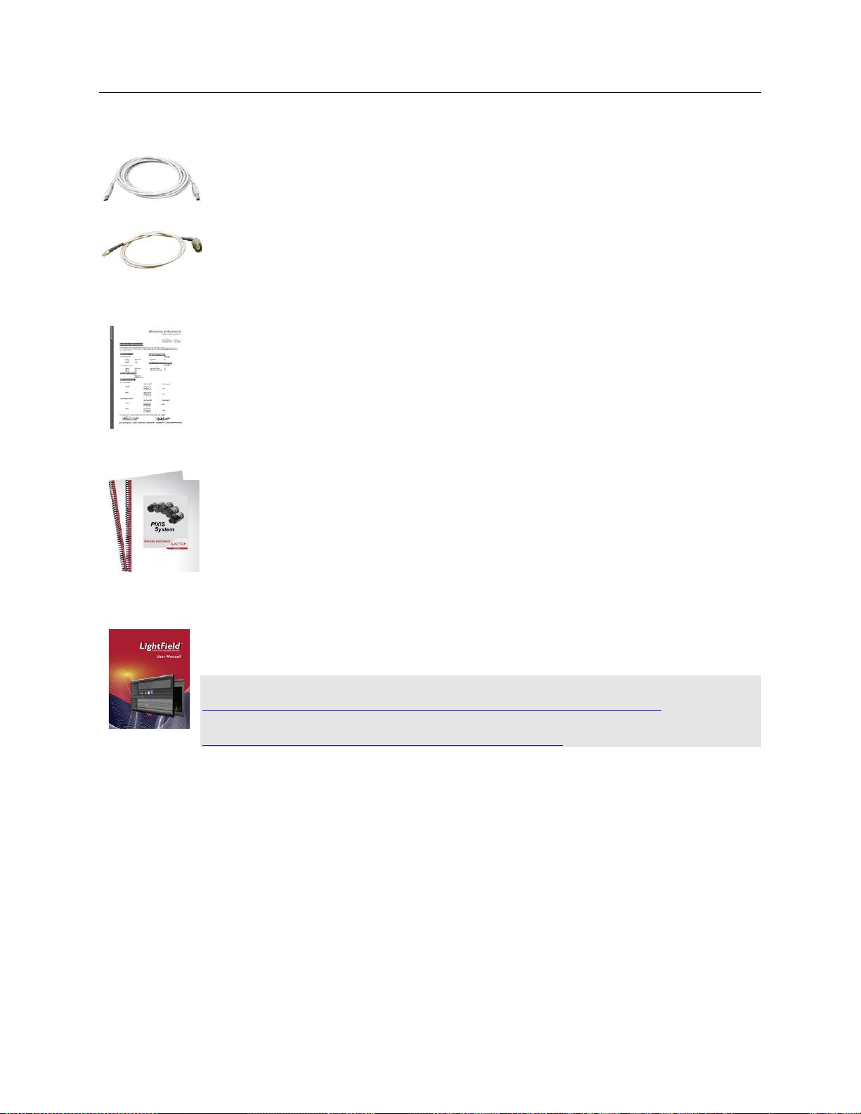
USB 2.0 Cable: The standard 16.4' (5 m) cable (6050-0494) has USB connectors that
interconnect the "USB 2.0" connector on the rear of the PIXIS with a USB card installed
in the host computer.
MCX to BNC Adapter Cables: Two MCX to BNC adapter cables are provided with
the PIXIS system. These mount to the EXT SYNC and the LOGIC OUT connectors on
the rear of the PIXIS.
Cables
Certificate of Performance
Each PIXIS camera has a Certificate of Performance. This certificate states that the
camera system was assembled and tested according to approved Princeton Instruments
procedures. It documents the camera performance data as measured during the testing of
your PIXIS and lists the Sales Order, Purchase Order, and Camera Serial numbers (useful
if you ever need to contact Princeton Instruments Customer Support).
User Manuals
PIXIS System User Manual: This manual describes how to install and use the PIXIS
system components.
WinView/32 or WinSpec/32 User Manual: This manual describes how to install and
use the application program. A PDF version of this manual is provided on the installation
CD. Additional information is available in the program's on-line help.
LightField® User Manual: This manual describes how to install and use the LightField
application program (for 64-bit Windows Vista® and Windows® 7 operating systems).
The manual is provided in PDF version on the installation CD and will be installed in the
Princeton Instruments/LightField/Documents subdirectory. Acrobat 7.0 or higher is
required. Additional information is available in the program's on-line help.
Note: You can download current versions of Princeton Instruments manuals at
ftp://ftp.princetoninstruments.com/Public/Manuals/Princeton Instruments/. The most
current versions of Acton manuals are located at
ftp://ftp.princetoninstruments.com/Public/Manuals/Acton/.

Chapter 2 System Component Descriptions 17
Optional Components
Application Software
WinX: The PIXIS camera can be operated by using either WinView/32 or
WinSpec/32, Princeton Instrument's 32-bit Windows® software packages designed
specifically for high-end imaging and spectroscopy, respectively. The Princeton
Instruments' software provides comprehensive image/spectral capture and display
functions. The package also facilitates snap-ins to permit advanced operation. Using
the optional built-in macro record function, you can also create and edit your own
macros to automate a variety of operations. WinView and WinSpec take full advantage
of the versatility of the PIXIS camera and even enhance it by making integration of the
detection system into larger experiments or instruments an easy, straightforward
endeavor.
PVCAM®: The standard software interface for cooled CCD cameras from Princeton
Instruments. It is a library of functions that can be used to control and acquire data
from the camera when a custom application is being written. For example, in the case
of Windows, PVCAM is a dynamic link library (DLL). Also, it should be understood
that PVCAM is solely for camera control and image acquisition, not for image
processing. PVCAM places acquired images into a buffer, where they can then be
manipulated using either custom written code or by extensions to other commercially
available image processing packages.
Scientific Imaging ToolKit™: SITK™ is a collection of LabVIEW® VIs for scientific
cameras and spectrographs. This third party software can be purchased from Princeton
Instruments.
LightField®: The PIXIS can be operated using LightField, Princeton Instrument’s
64-bit Windows Vista® and Windows® 7 compatible software package. LightField
combines complete control over Princeton Instruments’ cameras and spectrographs
with easy-to-use tools for experimental setup, data acquisition and post-processing.
LightField makes data integrity priority #1 via automatic saving to disk, time stamping
and retention of both raw and corrected data with full experimental details saved in
each file. LightField works seamlessly in multi-user facilities, remembering each user’s
hardware and software configurations and tailoring options and features accordingly.
The optional, patent-pending IntelliCal™ package is the highest-performance
wavelength calibration software available, providing up to 10X greater accuracy across
the entire focal plane than competing routines.
PICam™: The standard 64-bit software interface for cooled CCD cameras from
Princeton Instruments. PICam is an ANSI C library of camera control and data
acquisition functions. Currently, the interface supports Windows Vista and Windows 7.
Note: PIXIS may also be operated by several other third-party software packages.
Please check with the providers of the packages for compatibility and support
information.
18 PIXIS System Manual Version 2.C
Internal Shutter
Optional 25 or 45 mm internal shutter (dependent on CCD array size). Shutters are
mechanical devices with a finite lifetime, typically of the order of a million cycles,
although some individual shutters may last a good deal longer. How long a shutter lasts in
terms of experimental time will, of course, be strongly dependent on the operating
parameters. High repetition rates and short exposure times will rapidly increase the
number of shutter cycles and hasten the time when the shutter will have to be replaced.
F-Mount Adapter
An F-mount adapter (7050-0009) is available for modifying a spectroscopy-mount PIXIS
with internal shutter (see Figure 68, page 107).
Adjustable C- to Spectroscopy-Mount Kinetics Adapter
An adjustable C- to Spectroscopy-mount kinetics adapter is available for modifying a Cmount PIXIS for mounting to an Acton spectrograph. The adapter allows you to move the
camera vertically at the exit plane of an Acton Series spectrograph in order to align
kinetics rows at the middle of the focal plane for the best spectral quality. Two versions
are available: Model 7050-0104 for SP-2350 and SP-2550 spectrographs and
Model 7050-0107 for SP-2150 and SP-2750 spectrographs.
Fiber Optic Extender Kit
The specially designed fiber optic data interface kit allows the computer and the USB2.0
camera head to be separated by up to 500 meters without the loss of data. The kit consists
of two compact, high speed transceivers (interface modules) for completely transparent
operation between the host computer and the camera. The FO kit is ideal for hazardous or
high EMI environments. This optional kit supports PIXIS, Spec-10, VersArray and
PI-MAX family of products as well Acton Series spectrographs with USB2.0 data
interface.
CoolCUBEII with PIXIS-compatible Hoses (PN 7567-0002)
Liquid-cooled PIXIS cameras can cool to a lower temperature (typically -35 C) than air
cooling. Instead of using a fan to remove heat, these cameras incorporate a closed loop
system of circulating fluid. The CoolCUBEII circulator unit continuously pumps the
50:50 mixture of room temperature (23ºC) water and ethylene glycol. To prevent voiding
the warranty, use only the circulator and hoses shipped with your system.

Chapter 3
Action
Reference
1. If the system components have not already been unpacked, unpack
them and inspect their carton(s) and the system components for
in-transit damage.
Chapter 4 System Setup,
page 23
2. Verify that all system components have been received.
Chapter 4 System Setup,
page 24
3. If the components show no signs of damage, verify that the
appropriate power cord has been supplied with the power supply.
Chapter 4 System Setup,
page 24
4. If the application software is not already installed in the host
computer, install it.
Chapter 4 System Setup,
page 26 & Software manual
5. If a USB 2 interface card is not already installed in the host
computer, install it. Follow the manufacturer’s instructions.
6. Depending on application, attach lens to the camera or mount the
camera to a spectrograph.
Chapter 4 System Setup,
page 29
7. With the power supply disconnected from the camera, connect the USB
cable to the USB port at the rear of the camera and to the USB port at
the computer.
8. Air-Cooled System: Plug the power supply into the rear of the
camera and plug the power supply into the power source.
Liquid-Cooled System: Plug the power supply into the rear of the
camera and plug the power supply into the power source. Make the
hose connections to the camera. Plug the circulator into the power
source. Add coolant if necessary. Turn on the circulator.
Chapter 4 System Setup,
page 27
9. Turn the camera ON.
10. Turn on the computer and begin running the application software.
Software manual
11. Enter the hardware setup information or load the defaults from the
camera.
Chapter 5 Operation,
page 29
12. Set the target array temperature.
Chapter 5 Operation,
page 57
13. When the system reaches temperature lock, wait an additional 20
minutes and then begin acquiring data in focus mode.
Chapter 5 Operation,
page 38 or page 41
Initial System Verification
The list and diagrams below briefly describe the sequence of actions required to
install your system and prepare to gather data. Refer to the indicated references for
more detailed information.
19
20 PIXIS System Manual Version 2.C
Action
Reference
14. Adjust the focus for the best image or spectral lines. If you are using
WinSpec/32, you may want to use the Focus Helper function for
spectroscopy applications. If you are using LightField, you may
want to use the Align Spectrometer function.
Chapter 5 Operation,
page 45 or page 48
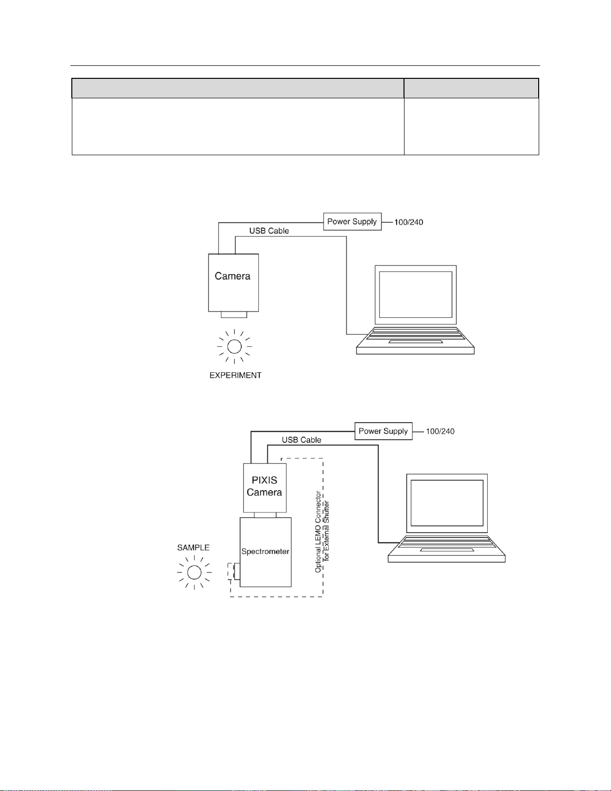
Figure 2. Typical Imaging Experiment Layout (Air-cooled Camera)
Figure 3. Typical Spectroscopy Experiment Layout (Air-cooled Camera)
Chapter 3 Initial System Verification 21
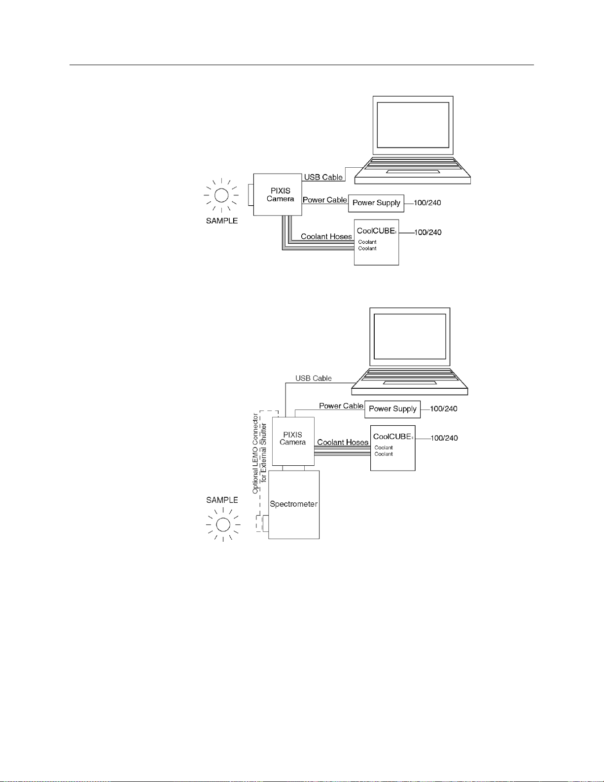
Figure 4. Typical Imaging Experiment Layout (Liquid-cooled Camera with CoolCUBEII)
Figure 5. Typical Spectroscopy Experiment Layout (Liquid-cooled Camera with CoolCUBEII)

22 PIXIS System Manual Version 2.C
This page intentionally left blank.

Chapter 4 System Setup
To minimize risk to users or to system equipment, turn the system OFF before any cables
are connected or disconnected.
Introduction
A PIXIS camera system consists of three hardware components:
Camera head
Power supply
Cables
All of the components and cables required for your configuration are included with your
shipment. Your PIXIS system has been specially configured and calibrated to match the
camera options specified at the time of purchase. The CCD and coating you ordered have
been installed in the camera head.
Keep all of the original packing materials so you can safely ship the PIXIS system to
another location or return it for service if necessary. If you have any difficulty with any
step of the instructions, call Princeton Instruments Customer Support. For contact
information, refer to page 132.
Hardware installation may consist of:
Installing an interface card, if the appropriate card is not already resident.
Attaching a lens to a C-mount on the camera or to an F-mount adapter.
Connecting the camera to an external shutter, if one is required.
Mounting the camera to a spectrograph.
Software installation depends on the application software you will be using to run the
system. Refer to the manual supplied with the software for information about installing
and setting it up.
Unpacking the System
During the unpacking, check the system components for possible signs of shipping
damage. If there are any, notify Princeton Instruments immediately and file a claim with
the carrier. If damage is not apparent but the camera cannot be operated, internal damage
may have occurred in shipment. After unpacking the system, save the original packing
materials so you can safely ship the camera system to another location or return it to
Princeton Instruments for repairs if necessary.
23

24 PIXIS System Manual Version 2.C
Checking the Equipment and Parts Inventory
Confirm that you have all of the equipment and parts required to set up the PIXIS system.
A complete system consists of:
Standard System:
Camera and Power Supply
CoolCUBEII Circulator and hoses (for liquid-cooled system)
Host Computer: Can be purchased from Princeton Instruments or provided by
user. For enhanced performance, a fast hard drive (10,000 rpm) and 2GB RAM is
recommended.
Operating System:
WinView/32 or WinSpec/32: Windows® XP (32-bit, SP3 or later), Vista ®
(32-bit), or Windows® 7 (32-bit).
LightField: Windows® Vista (64-bit) or Windows® 7 (64-bit)
USB cable: Five (5) meter cable (6050-0494) is standard.
PIXIS System User Manual
Options:
F-mount adapter
Adjustable C- to Spectroscopy-mount kinetics adapter
25 mm or 45 mm Internal Shutter (as appropriate for the CCD size)
Application Software:
WinView/32 or WinSpec32 (Ver. 2.5.25 or later) CD-ROM (optional)
LightField CD-ROM (optional)
Software User Manual (provided with application software)
Fiber Optic Extender Kit
System Requirements
Environmental Requirements
Storage temperature: 55°C
Operating environment temperature: +5ºC to +30ºC; the environment temperature
range over which system specifications can be guaranteed is +18ºC to +23ºC
Relative humidity 50%; non-condensing
Note: The cooling performance may degrade if the room temperature is above
+23°C.

Chapter 4 System Setup 25
Ventilation: Allow at least one inch clearance for the side air vents. Where the camera
is inside an enclosure, > 30 cfm air circulation and heat dissipation of 100W is required.
Power: The PIXIS camera receives its power from the supplied power supply which in
turn plugs into an AC power source.
Host Computer
Note: Computers and operating systems all undergo frequent revision. The following
information is only intended to give minimum computer requirements. Please contact the
factory to determine your specific needs.
WinX Requirements
Windows® XP (32-bit with SP3 or later), Vista® (32-bit), or Windows® 7 (32-bit)
2 GHz Pentium® 4 (or greater).
Native USB 2.0 support on the mother board or USB 2.0 Interface Card (Orange
Micro 70USB90011 USB2.0 PCI is recommended for desktop; SIIG, Inc. USB
2.0 PC Card, Model US2246 for laptop)
Minimum of 1 GB RAM (or greater).
CD-ROM drive.
Hard disk with a minimum of 1 Gbyte available. A complete installation of the
program files takes about 17-50 Mbytes and the remainder is required for data
storage, depending on the number and size of images/spectra collected. Disk level
compression programs are not recommended. Drive speed of 10,000 RPM
recommended.
Super VGA monitor and graphics card supporting at least 65,535 colors with at
least 128 Mbyte of memory. Memory requirement is dependent on desired
display resolution.
Mouse or other pointing device.
LightField Requirements
Windows Vista® (64-bit) or Windows® 7 (64-bit)
2 GHz dual core processor
4 GB RAM (or greater)
CD-ROM drive
Super VGA monitor and graphics card supporting at least 65535 colors with at
least 128 Mbyte of memory. Memory requirement is dependent on desired
display resolution.
Hard disk with a minimum of 1 Gbyte available for installation. Additional space
is required for data storage: the amount of space required depends on the number
and size of images/spectra collected. Disk level compression programs are not
recommended. Drive speed of 10,000 RPM recommended.
Mouse or other pointing device.
Note: The above requirements are the minimum for operating a PIXIS camera. A
faster computer with 5GB or larger memory (RAM) will greatly enhance the
software performance during live mode operations.
26 PIXIS System Manual Version 2.C
Windows Version
USB INF Filename
Located in
"Windows"/INF
directory*
USB Properties DLL
Located in
"Windows"/System3
2 directory
USB Device Driver Name
Located in
"Windows"/System32/Drivers
directory
Windows® XP,
Vista (32-bit),
Windows 7 (32-bit)
rsusb2k.inf (in
WINDOWS/INF,
for example)
apausbprop.dll (in
WINDOWS/System3
2, for example)
apausb.sys (in WINDOWS/
System32/Drivers, for
example)
* The INF directory may be hidden.
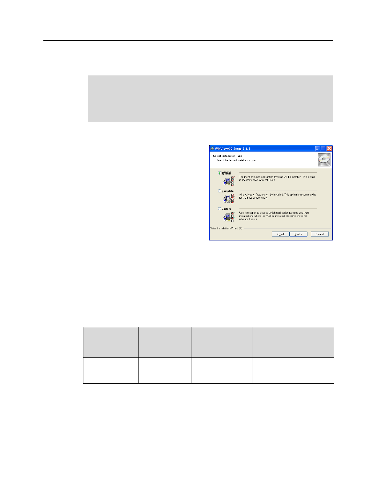
Figure 6. WinView Installation:
Select Installation Type dialog
Software Installation
WinX
Notes:
1. Before proceeding, please check to see if your computer supports USB 2.0. If it does
not, install a USB 2.0 interface card. Follow the manufacturer’s instructions.
2. Leave the USB cable disconnected from the camera until you have installed
WinView/32 or WinSpec/32.
The following installation is performed via the WinView/32 or WinSpec/32 software
installation CD.
1. On the Select Installation Type
dialog (see Figure 6), click on
Typical radio button to install the
required drivers and the most
commonly installed program files.
Select the Custom radio button if
you would like to choose among the
available program files or do not want
to install the drivers. Complete
installs all of the application features.
The required INF, DLL, and USB
driver files will be placed in the
appropriate "Windows" directories
(see Table 1 for locations).
2. Make sure the camera is connected to the host computer and that the camera power
supply is turned on.
3. Reboot the computer.
4. At bootup, Windows will detect the Princeton Instruments USB2 Interface hardware
in the PIXIS. You may be prompted to enter the directory path(s) for the
apausbprop.dll and/or the apausb.sys file(s), either by keyboard entry or by using the
browse function.
Table 1. USB Driver Files and Locations
Chapter 4 System Setup 27
LightField
The following installation is performed via the LightField software installation CD.
1. Before starting the installation:
Verify that the computer operating system is Windows Vista (64-bit) or
Windows 7 (64-bit).
Confirm that your computer supports USB 2.0. If it does not, please refer to the
manufacturer’s instructions for installing a USB 2.0 interface card.
Verify that your computer is connected to the Internet. Internet connection is
required for product activation.
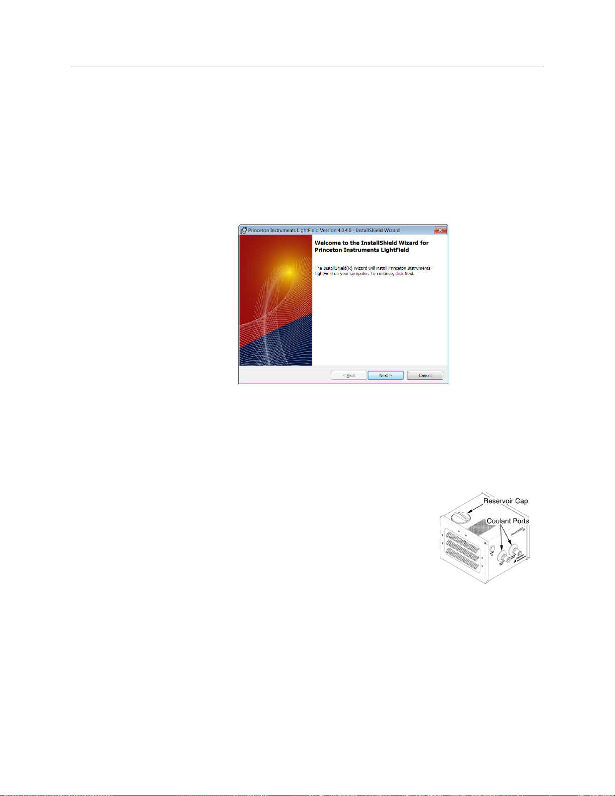
2. Insert the CD and follow the installation wizard prompts.
Figure 7. LightField Installation Wizard dialog
3. After the installation finishes, reboot the computer.
4. Connect the PIXIS system components to your computer and power them on.
5. Start LightField, activate it, and begin setting up your experiment.
Making the Camera-Circulator Connections for a CoolCUBEII
For liquid-cooled cameras, the CoolCUBEII circulator provides a
vibration-free method of heat removal.
1. Make sure the camera and the circulator power switches are
turned off.
2. Make sure the circulator is 6 inches (150 mm) or more
below the camera. The vertical distance should not exceed 10
feet (3 m). Typically, the camera is at table height and the circulator is on the floor.
3. Make the coolant connections between the circulator and the camera. It does not
matter which hose from the circulator is plugged into a coolant port on the camera.
4. It is recommended that hoses be secured to the camera hose barbs with the clamp
supplied.

28 PIXIS System Manual Version 2.C
Notes:
1. Make sure that there are no kinks in the hoses that impede the coolant flow. Lack
of sufficient flow can seriously harm the detector and any resulting damage is not
covered under warranty.
2. Damage caused by water leaking into the PIXIS voids the warranty.
5. Unscrew the reservoir cap (on top of the CoolCUBEII) and make
sure that the coolant reservoir contains coolant. If additional
coolant is required, fill with a 50:50 mixture of water and ethylene
glycol.
6. Screw the reservoir cap back in.
7. Plug the circulator into a 100-240 VAC, 47-63 Hz power source.
8. Turn the circulator on. Make sure there are no leaks or air bubbles in the hoses.
Note: Small air bubbles (about the size of bubbles in soda) are common in the
CoolCUBEII especially at start up and do not prevent proper operation.
If there are no problems, continue to Step 9.
If there are leaks or air bubbles, turn the circulator off and correct the problem(s)
by securing the hoses or adding more coolant to the reservoir. Turn the circulator
back on. Recheck and if there are no problems, continue to Step 9.
9. Turn the camera on.
10. Start the application software.
Chapter 4 System Setup 29
Entering the Default Camera System Parameters
The following instructions assume that you have performed the compute r interface
installation.
WinX
1. Make sure the PIXIS is connected to the host computer and that it is turned on.
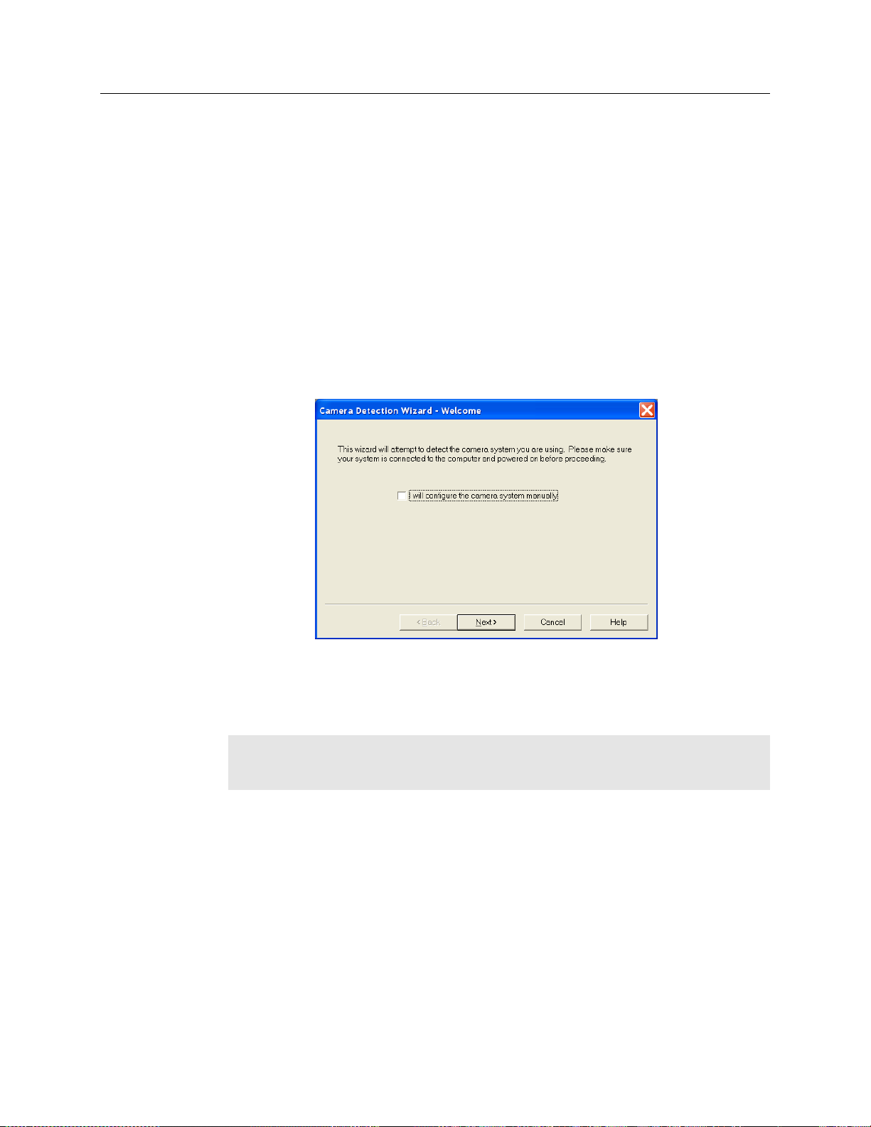
2. Run the WinX application. The Camera Detection wizard will automatically run if
this is the first time you have installed a Princeton Instruments WinX application
(WinView/32, WinSpec/32, or WinXTest/32) and a supported camera. Otherwise, if
you installing a new camera type, click on the Launch Camera Detection
Wizard… button on the Controller/CCD tab to start the wizard.
3. On the Welcome dialog (Figure 8), leave the checkbox unselected and click on
Next.
Figure 8. Camera Detection Wizard - Welcome dialog
4. Follow the instructions on the dialogs to perform the initial hardware setup: this
wizard enters default parameters on the Hardware Setup dialog tabs and gives you an
opportunity to acquire a test image to confirm the system is working.
Note: For a step-by-step procedure on basic system operation (Imaging and
Spectroscopy), refer to the appropriate "First Light" sections: for Imaging
applications (page 35) or for Spectroscopy applications (page 39).
LightField
1. Make sure the PIXIS (and spectrograph, if this is a spectroscopy system) is
connected to the host computer and that the camera (and spectrograph) power
supply is turned on.
2. Start LightField.
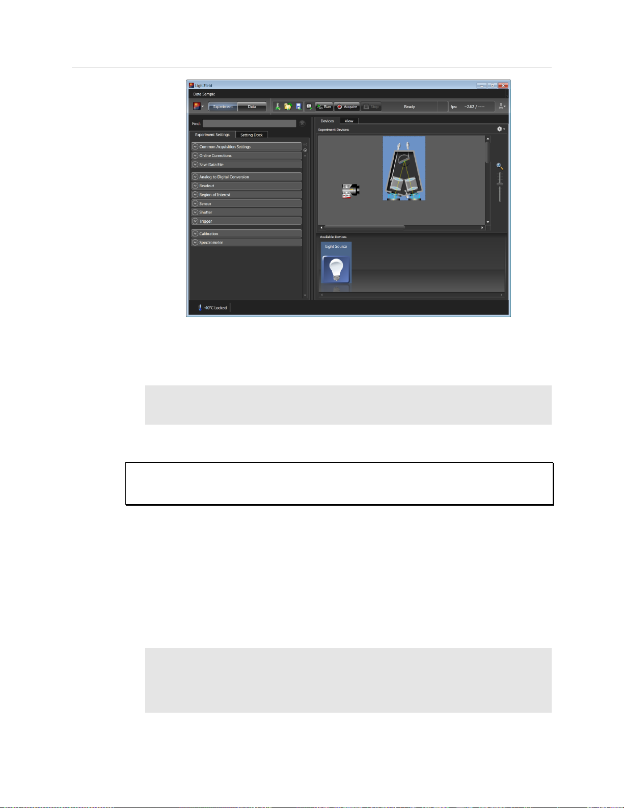
3. While LightField is starting up, it will detect the available device(s) and load the
appropriate icons into the Available Devices area in the Experiment workspace.
4. When you drag an icon into the Experiment Devices area, the appropriate
expanders will be loaded into the Experiment Settings stack on the lefthand side
of the window.
30 PIXIS System Manual Version 2.C
Caution
Figure 9. LightField Experiment Workspace
5. Because this is a new experiment, the default settings will automatically be
entered for the experiment device(s). These settings will allow you to begin
previewing (Run button) or acquiring (Acquire button) data.
Note: For a step-by-step procedure on basic system operation, refer to the appropriate
"First Light" sections: for Imaging applications (page 45) or for Spectroscopy
applications (page 48).
Attaching Lenses to C- and F-Mount Adapters
Overexposure protection: Cameras that are exposed to room light or other continuous
light sources will quickly become saturated. Set the lens to the smallest aperture (highest fnumber) and cover the lens with a lens cap to prevent overexposure.
PIXIS cameras for imaging applications incorporate an integral C-mount adapter, an
adjustable C-mount adapter, or an integral F-mount adapter. Other mounts may be available.
Consult the factory for specific information relating to your needs. See page 132 for
Information on accessing the Princeton Instruments Customer Support Dept.
Attaching to a C-Mount Adapter
C-mount lenses simply screw into the front of these cameras. Tighten the lens by hand
only. An optional C-to-F-mount adapter, which uses the Nikon bayonet format, can be
ordered. For information about adjusting the focal distance for an adjustable C-mount
adapter, refer to the instructions on page 109.
Note: C-mount cameras are shipped with a dust cover lens installed. Although this lens
is capable of providing surprisingly good images, its throughput is low and the image
quality is not as good as can be obtained with a high-quality camera lens. Users should
replace the dust-cover lens with their own high-quality laboratory lens before making
measurements.
 Loading...