

Page 1

4411-0097
Version 4.C
December 17, 2013
*4411-0097*
Page 2

Copyright 2003-2013 Princeton Instruments, a division of Roper Industries, Inc.
3660 Quakerbridge Rd
Trenton, NJ 08619
TEL: 800-874-9789 / 609-587-9797
FAX: 609-587-1970
All rights reserved. No part of this publication may be reproduced by any means without the written
permission of Princeton Instruments, a division of Roper Industries, Inc. ("Princeton Instruments").
Printed in the United States of America.
Kapton is a registered trademark of E. I. du Pont de Nemours and Company.
LabVIEW is a registered trademark of National Instruments Corporation.
Linux is a registered trademark of Linus Torvalds.
Macintosh is a trademark of Apple Computer, Inc., registered in the U.S. and other countries.
Pentium is a registered trademark of Intel Corporation.
PI-MTE is a trademark of Roper Industries, Inc.
Scientific Imaging ToolKit and SITK are trademarks of R Cubed Software Consultants, LLC.
Swagelok is a registered trademark of Crawford Fitting Company Corporation.
TAXI is a registered trademark of AMD Corporation.
VCR is a registered trademark of Cajon Company Corporation.
Microsoft, Windows, Windows XP, Windows Vista, and Windows 7 are registered trademarks of
Microsoft Corporation.
The information in this publication is believed to be accurate as of the publication release date. However,
Princeton Instruments does not assume any responsibility for any consequences including any damages
resulting from the use thereof. The information contained herein is subject to change without notice.
Revision of this publication may be issued to incorporate such change.
Page 3

Table of Contents
Chapter 1 Introduction .........................................................................................9
Description .......................................................................................................................... 9
Design ................................................................................................................................. 9
Grounding and Safety ......................................................................................................... 9
Precautions ........................................................................................................................ 10
Cleaning ............................................................................................................................ 11
Repairs .............................................................................................................................. 11
Manual Overview ............................................................................................................. 11
Chapter 2 System Component Descriptions ...................................................13
PI-MTE Camera ................................................................................................................ 13
ST-133 Controller ............................................................................................................. 13
Cables ............................................................................................................................... 16
Interface Card ................................................................................................................... 17
Vacuum Port Adapter ....................................................................................................... 17
Application Software ........................................................................................................ 18
User Manuals .................................................................................................................... 18
Optional Components ....................................................................................................... 18
Chapter 3 Installation Overview ........................................................................19
Chapter 4 System Setup ....................................................................................21
Unpacking the System ...................................................................................................... 21
Checking the Equipment and Parts Inventory .................................................................. 21
System Requirements ....................................................................................................... 22
Environmental ............................................................................................................ 22
Ventilation .................................................................................................................. 22
Coolant ....................................................................................................................... 22
Power .......................................................................................................................... 23
Host Computer ........................................................................................................... 23
Verifying Controller Voltage Setting ............................................................................... 24
Installing the WinView/32 Application Software ............................................................ 25
Setting up the Communication Interface .......................................................................... 25
Setting up a PCI Interface .......................................................................................... 25
Setting up a USB 2.0 Interface ................................................................................... 27
Connecting the Interface (Controller-Computer) Cable ................................................... 30
TAXI® Cable (6050-0148-CE) .................................................................................... 30
USB 2.0 Cable (6050-0494) ....................................................................................... 30
Connecting the Detector-Controller Cable ....................................................................... 30
Non-Vacuum .............................................................................................................. 30
Vacuum ...................................................................................................................... 31
Entering the Default Camera System Parameters into WinView ..................................... 32
Making the Coolant Connections ..................................................................................... 33
iii
Page 4

iv PI-MTE System Manual Version 4.C
Chapter 5 Operation ...........................................................................................35
Introduction ....................................................................................................................... 35
System On/Off Sequences ................................................................................................ 37
First Light ......................................................................................................................... 37
Assumptions ............................................................................................................... 37
Cabling ....................................................................................................................... 37
Getting Started ........................................................................................................... 38
Setting the Parameters ................................................................................................ 38
Acquiring Data ........................................................................................................... 39
Powering Down Procedure......................................................................................... 40
Cooling ............................................................................................................................. 41
Introduction ................................................................................................................ 41
Condensation .............................................................................................................. 41
Exposure and Signal ......................................................................................................... 42
Introduction ................................................................................................................ 42
CCD Array Architecture ............................................................................................ 42
Exposure Time ........................................................................................................... 43
Temperature Control .................................................................................................. 43
Dark Charge ............................................................................................................... 44
Saturation ................................................................................................................... 45
Clean Cycles ............................................................................................................... 45
Continuous Cleans ..................................................................................................... 46
Readout ............................................................................................................................. 46
Introduction ................................................................................................................ 46
Full Frame Readout .................................................................................................... 46
Binning ....................................................................................................................... 47
Hardware Binning ................................................................................................ 47
Software Binning ................................................................................................. 48
Background Subtraction ............................................................................................. 49
Digitization ....................................................................................................................... 49
Introduction ................................................................................................................ 49
Digitization Rate ........................................................................................................ 49
ADC Offset ................................................................................................................ 50
Chapter 6 Advanced Topics ..............................................................................51
Introduction ....................................................................................................................... 51
Standard Timing Modes ................................................................................................... 51
Free Run ..................................................................................................................... 52
External Sync ............................................................................................................. 53
External Sync with Continuous Cleans ...................................................................... 55
Fast and Safe Modes ......................................................................................................... 56
TTL Control ...................................................................................................................... 58
Introduction ................................................................................................................ 58
TTL In ........................................................................................................................ 58
Buffered vs. Latched Inputs ....................................................................................... 59
TTL Out ..................................................................................................................... 59
TTL Diagnostics Screen ............................................................................................. 60
Hardware Interface ..................................................................................................... 60
Example ............................................................................................................... 61
Page 5

Table of Contents v
Chapter 7 Troubleshooting................................................................................63
Introduction ....................................................................................................................... 63
Baseline Signal Suddenly Changes .................................................................................. 64
Camera1 (or similar name) on Hardware Setup dialog box ............................................. 64
Changing the ST-133 Line Voltage and Fuses ................................................................. 65
Controller Is Not Responding ........................................................................................... 67
Cooling Troubleshooting .................................................................................................. 67
Camera does not achieve temperature lock ................................................................ 67
Out-of-Vacuum Operation Cooling and Internal Vacuum Level ............................... 67
Camera loses temperature lock .................................................................................. 68
Data Loss or Serial Violation ........................................................................................... 69
Data Overrun Due to Hardware Conflict .......................................................................... 69
Data Overrun Occurred ..................................................................................................... 70
Error Creating Controller message ................................................................................... 70
Error Occurs at Computer Powerup ................................................................................. 71
Program Error ................................................................................................................... 73
Removing/Installing a Plug-In Module............................................................................. 74
Securing the Detector-Controller Cable Slide Latch ........................................................ 76
Serial violations have occurred. Check interface cable. ................................................... 77
Appendix A Specifications ................................................................................79
PI-MTE Camera ................................................................................................................ 79
CCD Arrays ................................................................................................................ 79
Environmental ............................................................................................................ 80
Power .......................................................................................................................... 80
Cooling ....................................................................................................................... 80
ST-133 .............................................................................................................................. 80
Appendix B Outline Drawings ...........................................................................83
Appendix C VCR and Swagelok Fittings ..........................................................87
VCR® Fittings ................................................................................................................... 87
Installation .................................................................................................................. 87
Gasket Replacement ................................................................................................... 88
Swaglok® Fittings ............................................................................................................. 88
Installation .................................................................................................................. 88
High Pressure Applications or High-Safety-Factor Systems ..................................... 89
Retightening Instruction ............................................................................................. 89
Appendix D Visible <-> Open Nose Change Instructions ...............................91
Introduction ....................................................................................................................... 91
Replacing the Visible Nose with the Open Nose ............................................................. 91
Replacing the Open Nose with the Visible Nose ............................................................. 93
Appendix E USB 2.0 Limitations .......................................................................95
Declaration of Conformity .................................................................................97
Page 6

vi PI-MTE System Manual Version 4.C
Warranty & Service.............................................................................................99
Limited Warranty: ............................................................................................................ 99
Basic Limited One (1) Year Warranty ....................................................................... 99
Limited One (1) Year Warranty on Refurbished or Discontinued Products.............. 99
XP Vacuum Chamber Limited Lifetime Warranty .................................................... 99
Sealed Chamber Integrity Limited 12 Month Warranty .......................................... 100
Vacuum Integrity Limited 12 Month Warranty ....................................................... 100
Image Intensifier Detector Limited One Year Warranty ......................................... 100
X-Ray Detector Limited One Year Warranty .......................................................... 100
Software Limited Warranty ...................................................................................... 100
Owner's Manual and Troubleshooting ..................................................................... 101
Your Responsibility ................................................................................................. 101
Contact Information ........................................................................................................ 102
Index ..................................................................................................................103
Figures
Figure 1. PI-MTE Camera ................................................................................................. 9
Figure 2. Power Switch Location (ST-133A and ST-133B) ........................................... 14
Figure 3. PI-MTE System Diagram ................................................................................. 20
Figure 4. Controller Power Module ................................................................................. 24
Figure 5. WinView/32 Installation: Select Installation Type dialog .............................. 25
Figure 6. Camera Detection Wizard - Welcome dialog ................................................... 32
Figure 7. Coolant Ports .................................................................................................... 33
Figure 8. Block Diagram of Signal Path in System ......................................................... 36
Figure 9. Example of WinView Data Acquired from First Light Procedure .................. 40
Figure 10. Clean Cycles in Freerun Operation ................................................................ 45
Figure 11. Array Terms for a CCD with a Single Output Amplifier ............................... 46
Figure 12. Full Frame at Full Resolution ........................................................................ 47
Figure 13. 2 × 2 Binning for Images ................................................................................ 48
Figure 14. Timing tab page .............................................................................................. 51
Figure 15. Free Run Timing Chart, Part of the Chart in Figure 21 ................................. 52
Figure 16. Free Run Timing Diagram ............................................................................. 53
Figure 17. Chart Showing Two External Sync Timing Options ..................................... 54
Figure 18. Timing Diagram for External Sync Mode (- edge trigger)............................. 54
Figure 19. Continuous Cleans Operation Flowchart ....................................................... 55
Figure 20. Continuous Cleans Timing Diagram (- edge trigger) ..................................... 56
Figure 21. Chart of Safe Mode and Fast Mode Operation .............................................. 57
Figure 22. TTL In/Out Connector ................................................................................... 60
Figure 23. TTL Diagnostics dialog box ........................................................................... 60
Figure 24. Camera1 in Controller Type (Camera Name) Field ....................................... 64
Figure 25. Power Module ................................................................................................ 66
Figure 26. Voltage Selector Drum ................................................................................... 66
Figure 27. Fuse Holder .................................................................................................... 66
Figure 28. Data Overrun Due to Hardware Conflict dialog box ..................................... 69
Figure 29. Error Creating Controller dialog box ............................................................. 70
Figure 30. Program Error dialog box ............................................................................... 73
Page 7

Table of Contents vii
Figure 31. Module Installation ........................................................................................ 74
Figure 32. Serial Violations Have Occurred dialog box ................................................. 77
Figure 33. PI-MTE Camera (3-01-06 and later) .............................................................. 83
Figure 34. PI-MTE Camera (8-01-05 and later) .............................................................. 84
Figure 35. PI-MTE Camera (8-01-05 and earlier) ........................................................... 85
Figure 36. ST-133A Controller ........................................................................................ 86
Figure 37. ST-133B Controller ........................................................................................ 86
Figure 38. VCR Fittings .................................................................................................. 87
Tables
Table 1. PCI Driver Files and Locations ......................................................................... 26
Table 2. USB Driver Files and Locations ........................................................................ 29
Table 3. Camera Timing Modes ...................................................................................... 51
Table 4. Bit Values with Decimal Equivalents: 1 = High, 0 = Low ............................... 59
Table 5. TTL In/Out Connector Pinout ........................................................................... 60
Table 6. Fuse Ratings ....................................................................................................... 65
Table 7. I/O Address & Interrupt Assignments before Installing Serial Card ................. 71
Table 8. I/O Address & Interrupt Assignment after Installing Serial Card ..................... 72
Table 9. Features Supported under USB 2.0 (continued on next page) .......................... 95
Page 8

viii PI-MTE System Manual Version 4.C
This page intentionally left blank.
Page 9
Chapter 1
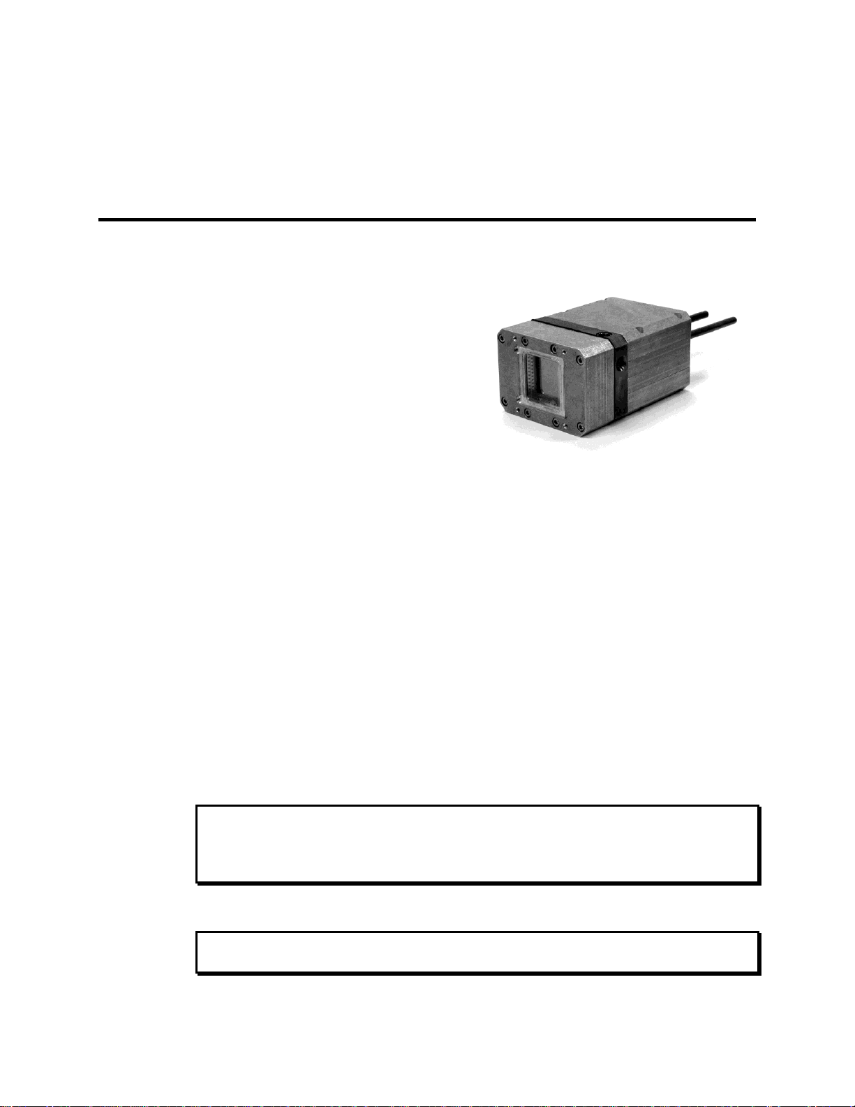
The PI-MTE camera is ideally suited for
operation inside a vacuum chamber. Stateof-the-art CCD arrays are available for the
PI-MTE camera that enable outstanding
performance in a wide range of X-ray
Imaging and Spectroscopy applications.
The PI-MTE camera is also suitable for
medium-low light applications that require
small size or steel case ruggedness.
Figure 1. PI-MTE Camera
WARNING!
WARNING!
Introduction
Description
Design
PI-MTE cameras have three distinct sections. The front enclosure contains the CCD
array seated on a cold finger. This finger is in turn seated on a two-stage Peltier
thermoelectric cooler. The middle enclosure contains the heat exchanger. The rear
enclosure contains the preamplifier and array driver boards. This keeps all signal leads to
the preamplifier as short as possible, and also provides RF shielding.
Grounding and Safety
The ST-133 Controller that controls the PI-MTE camera is of Class I category as defined
in IEC Publication 348 (Safety Requirements for Electronic Measuring Apparatus). It is
designed for indoor operation only. Before turning on the controller, the ground prong of
the power cord plug must be properly connected to the ground connector of the wall
outlet. The wall outlet must have a third prong, or must be properly connected to an
adapter that complies with these safety requirements.
If the equipment is damaged, the protective grounding could be disconnected. Do not use
damaged equipment until its safety has been verified by authorized personnel.
Disconnecting the protective earth terminal, inside or outside the apparatus, or any
tampering with its operation is also prohibited.
9
If the PI-MTE camera system is used in a manner not specified by Princeton Instruments,
the protection provided by the equipment may be impaired.
Page 10

10 PI-MTE System Manual Version 4.C
WARNING!
Inspect the supplied power cord. If it is not compatible with the power socket, replace the
cord with one that has suitable connectors on both ends.
Replacement power cords or power plugs must have the same polarity and power rating
as that of the original ones to avoid hazard due to electrical shock.
Precautions
To prevent permanently damaging the system, please observe the following precautions:
Do not mix and match ST-133 Controllers and cameras. The controller shipped
with your camera has been modified to operate with the camera included in the
PI-MTE system you ordered. The "System ID" number on the camera and the
controller serial labels must be the same.
Always switch off and unplug the ST-133 Controller before changing your
system configuration in any way.
The CCD array is very sensitive to static electricity. Touching the CCD can
destroy it. Operations requiring contact with the device can only be performed at
the factory.
If you are using high-voltage equipment (such as an arc lamp) with your camera
system, be sure to turn the controller power ON LAST and turn the controller
power OFF FIRST.
Use caution when triggering high-current switching devices (such as an arc
lamp) near your system. The CCD can be permanently damaged by transient
voltage spikes. If electrically noisy devices are present, an isolated, conditioned
power line or dedicated isolation transformer is highly recommended.
Never connect or disconnect any cable while the system is powered on.
Reconnecting a charged cable may damage the CCD.
Never prevent the free flow of air through the Model ST-133 by blocking the air
vents.
Never operate a liquid-assisted PI-MTE camera with coolant at a temperature
below that specified for it.
Page 11

Chapter 1 Introduction 11
Cleaning
Turn off all power to the equipment and secure all covers before cleaning the units.
Otherwise, damage to the equipment or personal injury could occur.
Normally, PI-MTE cameras operated in vacuum will remain clean by virtue of the
vacuum. Periodic cleaning of the controller is encouraged in accordance with the
controller manual.
Although there is no periodic maintenance that must be performed on the PI-MTE
camera, users of a non-vacuum camera are advised to wipe it down with a clean damp
cloth from time to time. This operation should only be done on the external surfaces and
with all covers secured. In dampening the cloth, use clean water only. No soap, solvents
or abrasives should be used. Not only are they not required, but they could damage the
finish of the surfaces on which they are used.
Note: Some discoloration of the copper portions of the camera may occur. This is
normal and has no effect on operation.
Repairs
Save the original packing materials. Because the PI-MTE camera system contains no
user-serviceable parts, repairs must be done by Princeton Instruments. Should your
system need repair, contact Princeton Instruments Customer Support for instructions
(telephone, e-mail, and address information are provided on page 102 of this manual).
Use the original packing materials whenever shipping the system or system components.
Manual Overview
This manual provides the user with all the information needed to install a PI-MTE
camera and place it in operation. Topics covered include a detailed description of the
camera, installation, cleaning, specifications and more.
Notes:
1. The general identifier "ST-133" is used for both the ST-133A Controller and the
ST-133B Controller. Where there is a difference, the specific identifier is used.
2. "WinX" is a generic term for WinView, WinSpec, and WinXTest application
software.
Chapter 1, Introduction provides general information about the PI-MTE camera
system including information about precautions, cleaning, repairs, and the
manual structure.
Chapter 2, System Component Descriptions provides information about the
camera, controller, interface card, cables and application software.
Chapter 3, Installation Overview provides directions for setting up the system
components.
Page 12

12 PI-MTE System Manual Version 4.C
Chapter 4, System Setup provides detailed directions for setting up a PI-MTE
camera for imaging applications.
Chapter 5, Operation discusses baseline signal and noise, setting and maintaining
temperature control, and verifying camera operation.
Chapter 6, Advanced Topics discusses standard timing modes (Free Run,
External Sync, and Continuous Cleans), Fast and Safe triggering modes, and
TTL control.
Chapter 7, Troubleshooting provides courses of action to take if you should
have problems with your system.
Appendix A, Specifications includes camera specifications.
Appendix B, Outline Drawings includes outline drawings of the PI-MTE camera
and the ST-133A and ST-133B Controllers.
Appendix C, VCR and Swagelok Fittings includes instructions for assembling
VCR® and Swagelok® tube fittings.
Appendix D, Visible <-> Open Nose Change Instructions includes
instructions for changing the PI-MTE nose from its visible nose (with test lens)
to its open nose configuration and vice versa.
Appendix E, USB 2.0 Limitations covers the currently known limitations
associated with operating under the USB 2.0 interface.
Declaration of Conformity is the Declaration of Conformity for MTE2 Camera
Head with ST-133 Controller (i.e., PI-MTE system).
Warranty and Service details the limited warranties for Princeton Instruments
equipment and software.
Page 13

Chapter 2 System Component Descriptions
PI-MTE Camera
CCD Arrays: The PI-MTE:1300B and PI-MTE:2048B incorporate a back-illuminated
CCD without AR coating for very low-energy x-ray detection. With 20×20-micron
(1300B) or 13.5×13.5-micron (2048B) pixels and 100% fill factor, these systems offer a
large imaging area with very high spatial resolution and dynamic range.
Cooling: Dark current is significantly reduced in PI-MTE camera systems through
liquid-assisted Thermo-electric (TE) cooling of the CCD array.
Peltier: An internal Peltier device directly cools the cold finger on which the CCD is
mounted. The heat produced by the Peltier device is then removed by conduction to
the internal heatsink. Heat is transferred out of the camera by the flow of coolant
through the heatsink.
Coolant Ports: Two 1/4" coolant ports are located at the rear of the camera.
Connection to a vacuum flange is via VCR fittings (or Swagelok fittings) and
stainless steel, flexible hoses. Instructions for setting up coolant flow are provided on
page 32.
Controller Connector: Power, control signals, and data are transmitted between the
ST-133 and the PI-MTE camera via the 25-pin D connector located on the rear of the
camera. Controller power must be OFF before connecting to or disconnecting from
this connector or to the equivalent connector on a vacuum flange.
ST-133 Controller
Electronics: The ST-133 controller is a compact, high performance CCD Detector
Controller for operation with Princeton Instruments brand* detectors. Designed for high
speed and high performance image acquisition, the ST-133 offers data transfer at speeds
up to 1 megapixel per second, standard video output for focusing and alignment. A
variety of A/D converters are available to meet different speed and resolution
requirements.
In addition to containing the power supply, the controller contains the analog and digital
electronics, scan control and exposure timing hardware, and controller I/O connectors,
all mounted on user-accessible plug-in modules. This highly modularized design gives
flexibility and allows for convenient servicing.
*
The ST-133 controller must be factory configured for operation with a TE-cooled camera. For
this reason, a controller purchased for operation with a TE-cooled camera can only be used with
TE-cooled camera. It cannot be used to control an LN-cooled camera.
13
Page 14
14 PI-MTE System Manual Version 4.C
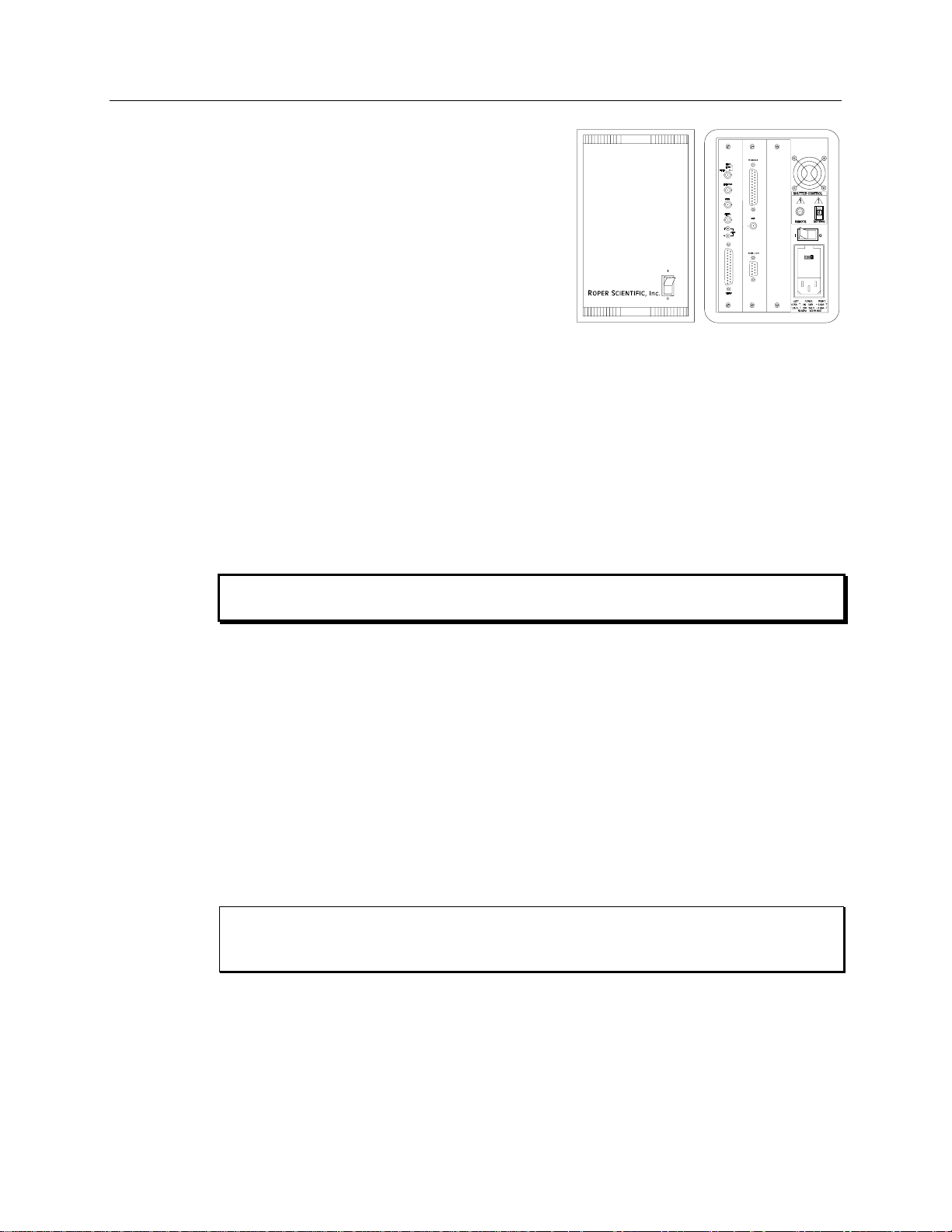
POWER Switch and Indicator: The power
switch location and characteristics depend on the
version of ST-133 Controller that was shipped
with your system. In some versions, the power
switch, located on the front panel as shown in
Figure 2, has an integral indicator LED that lights
whenever the ST-133 is powered. In other
versions, the power switch is located on the back
of the ST-133 and does not include an indicator
LED.
Rear Panel Connectors: There are three
controller board slots. Two are occupied by the
plug-in cards that provide various controller
Figure 2. Power Switch Location
(ST-133A and ST-133B)
Pixel A/D conversion
Timing and synchronization of readouts
CCD scan control
Temperature control
Exposure control
Video output control
WARNING!
WARNING!
functions. The third, covered with a blank panel, is reserved for future development. The
left-most plug-in card is the Analog/Control module. Adjacent to it is the Interface
Control module. Both modules align with top and bottom tracks and mate with a passive
back-plane via a 64-pin DIN connector. For proper operation, the location of the modules
should not be changed. Each board is secured by two screws that also ground each
module’s front panel. The connectors and functions located on the rear panel are further
are described on the following page. Removing and inserting boards is described in
Chapter 7, page 74.
To minimize the risk of equipment damage, a module should never be removed or
installed when the system is powered.
The Analog/Control Module, which must always be located in the left-most slot,
provides the following functions.
The Interface Control Module, which must always be located in the center slot,
provides the following functions.
TTL In/Out Programmable Interface
Communications Control (TAXI or USB 2.0 protocol)
Always turn the power off at the Controller before connecting or disconnecting any cable
that interconnects the camera and controller or serious damage to the CCD may result.
This damage is NOT covered by the manufacturer’s warranty.
Page 15
Chapter 2 System Component Descriptions 15
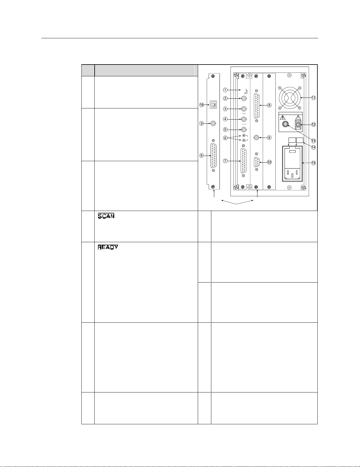
#
Feature
120Vac
50-60Hz
FUSES: LEFT: RIGHT:
100 - 120V ~ 0.75A - T 2.50A - T
220 - 240 V ~ 0.30A - T 1.25 A-T
SHUTTER CONTROL
REMOTE
SETTING
TTL IN/OUT
AUX
VIDEO
TEMP
LOCK
EXT SYNC
SCAN
READY
ZERO
F
S
DETECTOR
TTL
IN/OUT
AUX
USB 2.0
SERIAL COM
USB 2.0TAXI
Interface Control Module
1
Temperature Lock LED: Indicates that
the temperature control loop has locked
and that the temperature of the CCD
array will be stable to within 0.05C.
2
Video/Aux Output: If labeled Video,
composite video output is provided at this
connector. The amplitude is 1 V pk-pk and
the source impedance is 75 . Note that
video output is not currently supported
under USB 2.0. If labeled Aux, this output
is reserved for future use.
3
External Sync Input: TTL input that has
a 10 k pullup resistor. Allows data
acquisition and readout to be
synchronized with external events.
Through software, positive or negative
(default) triggering can be selected.
4
Output: WinView/32 (ver. 2.4 and
higher) software selectable NOT SCAN or
SHUTTER signal. Default is SHUTTER.
10
Serial COM Connector: Provides two-way
serial communication between the controller
and the host computer. Uses TAXI protocol.
5
Output: Initially HIGH. After a
Start Acquisition command, this output
changes state on completion of the array
cleaning cycles that precede the first
exposure. Initially high, it goes low to
mark the beginning of the first exposure.
In free run operation it remains low until
the system is halted. If a specific number
of frames have been programmed, it
remains low until all have been taken,
then returns high.
11
Fan: Cools the controller electronics.
Runs continuously when the controller is
turned on.
12
Shutter Setting Selector: Sets the shutter
drive voltage. Dial is correctly set at the
factory for the camera’s internal shutter if
one is present.
6
Zero Adjustment: Bias potentiometers
control the offset values of the Fast (F) and
Slow (S) A/D converters. Preadjusted at
factory. For 2 MHz controllers, baseline
offset values are set at the factory and are
not user-changeable.
CAUTION: Do not adjust the offset
values to zero, or some low-level data
will be missed.
13
Remote Shutter Connector: Provides
shutter-drive pulses for an external shutter.
An ST-133 with the 70 V shutter option is
required for a camera with the 40 mm
shutter. A 70 V OPT label will be next to the
Remote connector when this option is
installed.
7
Detector Connector: Transmits control
information to the camera and receives
data back from the camera via the
Detector-Controller cable.
14
Power Module: Contains the power cord
socket and two fuses. Depending on the
ST-133 version, the power switch may be
located directly above the power module.
Rear Panel Features: The rear panel connector descriptions are keyed to the
accompanying figure. The Fuse/Voltage label will be above or below the Power Module.
Page 16
16 PI-MTE System Manual Version 4.C
#
Feature
#
Feature
8
TTL In/Out: User-programmable
interface with eight input bits and eight
output bits that can be written to or
polled for additional control or
functionality. Refer to "TTL Control",
page 58.
15
Fuse/Voltage Label: Displays the
controller’s power and fuse requirements.
This label may appear below the power
module.
9
AUX Output: Reserved for future use.
16
USB 2.0 Connector: Provides two-way
serial communication between the controller
and the host computer. Uses USB 2.0
protocol.
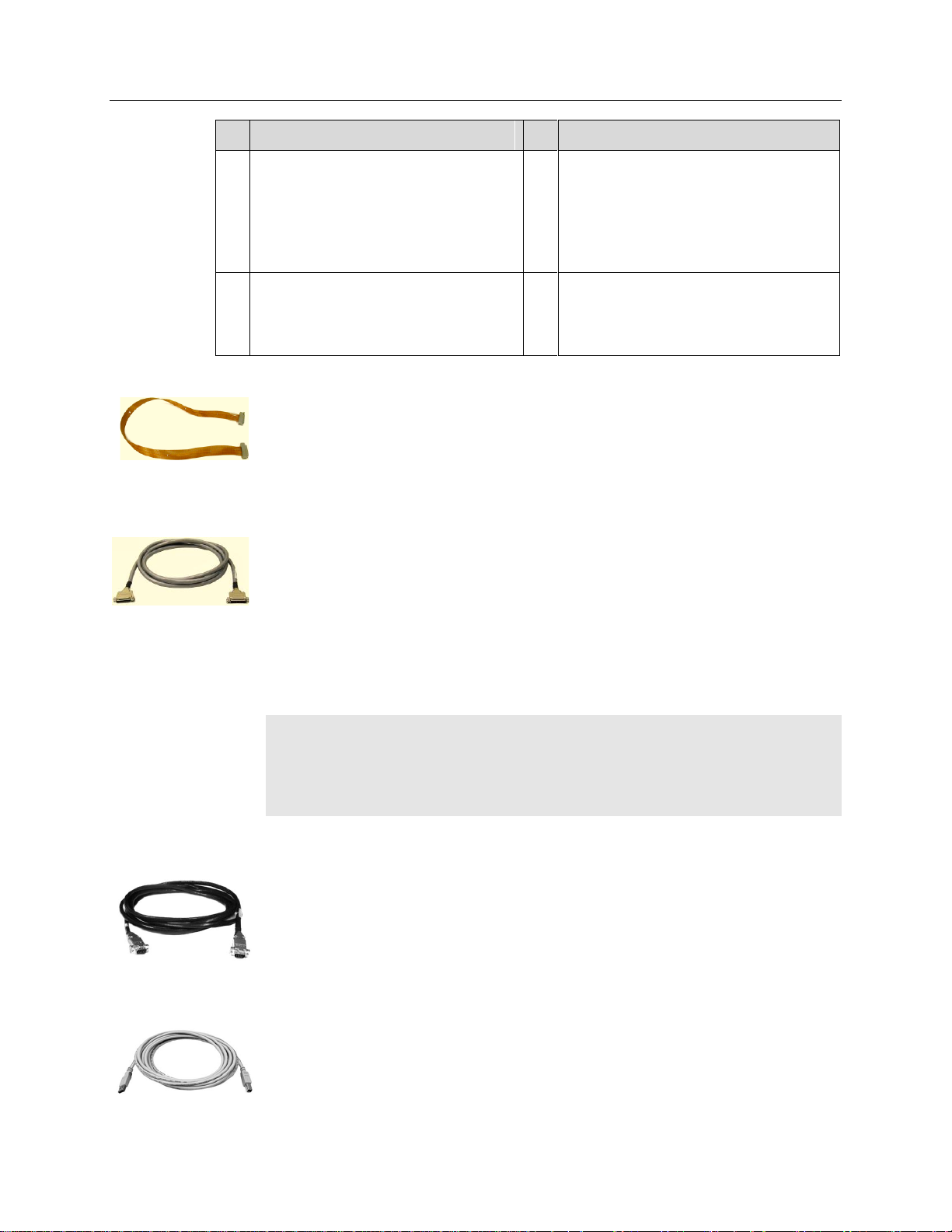
Vacuum-Compatible Camera-Vacuum Cable: This 1-meter cable has
DB-25 connectors that interconnect the DB-25 connector on the back of the camera
and a 25-pin D connector on a compatible vacuum flange. Available in Kapton®
flat cable (6050-0467) or in low vacuum cable with braided sleeve (6050-0475).
The low vacuum cable is also available in 1.5 meter and 2 meter lengths.
Detector-Controller: (6050-0526) 50 kHz/2 MHz systems: The standard 3'
cable has DB-25 connectors (one with slide-latch locking hardware to secure at the
controller and the other with screws for securing to a vacuum flange). This cable
interconnects the Detector connector on the rear of the ST-133 and the DB-25
connector on a compatible vacuum flange.
Detector-Controller: (6050-0483) 100 kHz/1 MHz systems: The standard 6'
cable has DB-25 connectors (one with slide-latch locking hardware to secure at the
controller and the other with screws for securing to a vacuum flange). This cable
interconnects the Detector connector on the rear of the ST-133 and the DB-25
connector on a compatible vacuum flange.
Note: If the PI-MTE camera is being operated out-of-vacuum (i.e., with the visible
nose, containing a quartz window, mounted to the front of the camera for operation in a
non-vacuum environment), an optional 10' cable (6050-0321), with slide latches at both
ends, is available to directly interconnect the PI-MTE camera and the ST-133. DetectorController. Cables 15' and 20' long are also available for out-of-vacuum operation.
Interface Cable: Depending on the system configuration, either a USB or a TAXI
cable will be shipped.
TAXI: The standard 25' (7.6 m) cable (6050-0148-CE) has DB-9 Male
connectors with screw-down locking hardware. The TAXI (Serial
communication) cable interconnects the "Serial Com" connector on the rear of the
ST-133 with the Princeton Instruments (RSPI) high speed PCI card installed in the
host computer. In addition to the standard length, this cable is available in 10', 50',
100', and 165' lengths. Also available are fiber optic adapters with fiber optic
cables in 100, 300, and 1000 meter lengths.
USB 2.0: The standard 16.4' (5 m) cable (6050-0494) has USB connectors
that interconnect the "USB 2.0" connector on the rear of the ST-133 with a
USB card installed in the host computer.
Cables
Page 17
Chapter 2 System Component Descriptions 17
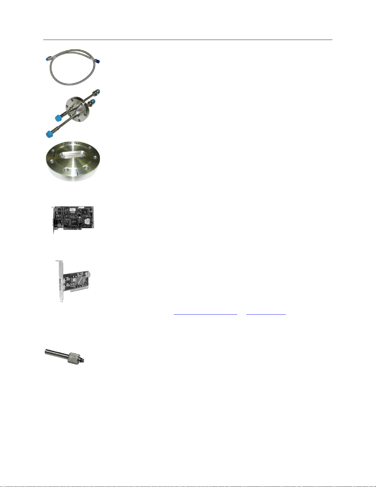
Vacuum Compatible Flexible Tubing: The stainless-steel vacuum-compatible
¼″-OD, 36″-long flexible tubing (2825-0449) interconnects between the camera
water tubings and the vacuum feed through a 2 ¾″ ConFlat flange.
Vacuum Compatible Camera Flanges: The 2 ¾″ ConFlat flange with two
pipes (¼″ OD) and VCR fittings (2825-0562) (or with Swagelok fittings
(2825-0447) for earlier systems) and the 4 ½″ ConFlat flange with 25-pin D-sub
connector (2825-0448) are included with the system.
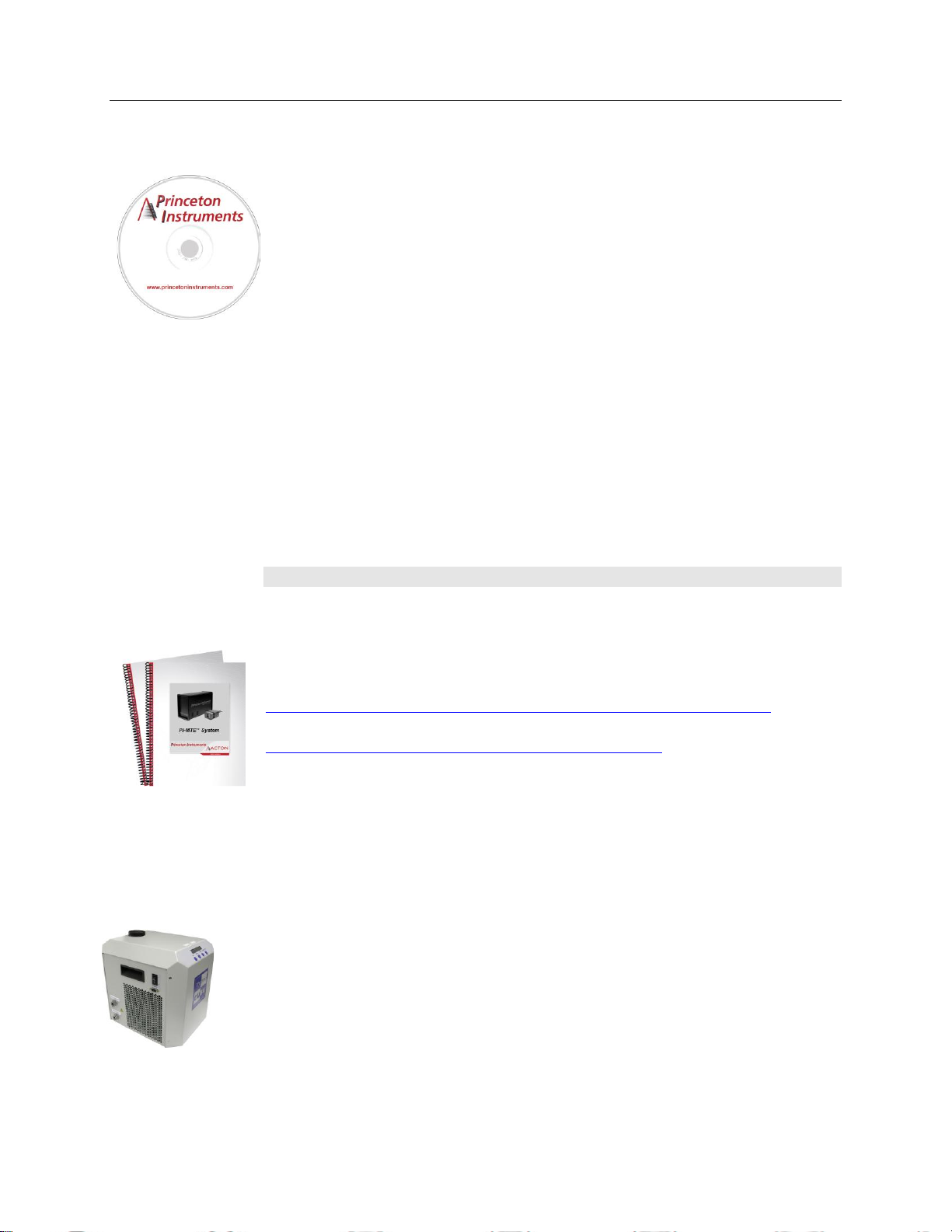
Interface Card
PCI Card: The Princeton Instruments (RSPI) high speed PCI card is required when
the system interface uses the TAXI protocol rather than USB 2.0. The PCI card plugs-
into the host computer's motherboard and provides the serial communication interface
between the host computer and the ST-133. Through WinView/32, the card can be
used in either High Speed PCI or PCI (Timer) mode. High Speed PCI allows data
transfer to be interrupt-driven and can give higher performance in some situations. PCI
(Timer) allows data transfer to be controlled by a polling timer.
USB 2.0 Card: This interface card is required when the system interface uses the
USB 2.0 protocol rather the TAXI protocol and the computer does not have native
USB 2.0 support. The USB 2.0 card plugs-into the host computer's motherboard and
provides the communication interface between the host computer and the ST-133.
The USB 2.0 PCI card (70USB90011) by Orange Micro is recommended for desktop
computers; the SIIG, Inc. USB 2.0 PC Card, Model US2246 is recommended for
laptop computers. Refer to www.orangemicro.com or www.siig.com, respectively,
for more information.
Vacuum Port Adapter
The Vacuum Port Adapter (2518-0943) with O-ring screws into the vacuum port on
the side of the PI-MTE. This allows you to connect the camera (with visible nose) to
a vacuum pump and pump it down to at least 1 mTorr before using the camera in a
non-vacuum environment.
Page 18
18 PI-MTE System Manual Version 4.C
Application Software
The Princeton Instruments WinView/32 software package provides comprehensive
image acquisition, display, processing, and archiving functions so you can perform
complete data acquisition and analysis without having to rely upon third-party software.
WinView/32 provides reliable control over most Princeton Instruments cameras,
regardless of array format and architecture, via an exclusive universal
programming interface (PVCAM®). WinView/32 also features snap-ins and macro
record functions to permit easy user customization of any function or sequence.
PVCAM is the standard software interface for cooled CCD cameras from
Princeton Instruments. It is a library of functions that can be used to control and
acquire data from the camera when a custom application is being written. For
example, in the case of Windows, PVCAM is a dynamic link library (DLL). Also,
it should be understood that PVCAM is solely for camera control and image
acquisition, not for image processing. PVCAM places acquired images into a
buffer, where they can then be manipulated using either custom written code or by
extensions to other commercially available image processing packages.
Scientific Imaging ToolKit™ (SITK™) is a collection of LabVIEW
scientific cameras and spectrographs. This third party software can be purchased
from Princeton Instruments.
®
VIs for
Note: Linux
User Manuals
PI-MTE System User Manual: This manual describes how to install and use
the PI-MTE system components. The most up-to-date version of this manual and
other Princeton Instruments manuals can be found and downloaded from
ftp://ftp.princetoninstruments.com/Public/Manuals/Princeton Instruments. The
most current versions of Acton manuals are located at
ftp://ftp.princetoninstruments.com/Public/Manuals/Acton.
WinView/32 User Manual: This manual describes how to install and use the
application program. A PDF version of this manual is provided on the installation
CD. Additional information is available in the program's on-line help.
PVCAM Manual: This manual describes PVCAM parameters and ids and
provides example code. Provided as PDF manual only.
Optional Components
ThermoCUBE with PI-MTE-compatible Hoses (PN 8243-0002): The
ThermoCUBE is a compact liquid chiller that is designed for Princeton Instruments’
Quad-RO and PI-MTE deep cooled cameras. ThermoCUBE, with a self-contained water
reservoir that provides chilled liquid circulation for efficiently cooling the cameras, is
ideal for applications that require vibration-free and/or thermally stable environments.
®
drivers are also available.
Page 19

Chapter 3
Action
Reference
1. If the system components have not already been
unpacked, unpack them and inspect their carton(s) and
the system components for in-transit damage.
Chapter 4, page 21
2. Verify that all system components have been received.
Chapter 4, page 21
3. With the ST-133 turned OFF, verify that the
appropriate line voltage and fuses have been installed in
the ST-133 controller.
Chapter 4, page 24
4. If using WinView/32 software to control your system,
install that software if it has not already been installed.
Refer to the WinView/32
manual.
5. If the appropriate interface card is not already installed
in the host computer, install it.
Chapter 4, page 25
6. With the computer and ST-133 both OFF, connect the
interface cable (TAXI or USB) to the Controller and the
interface card in the host computer. Then tighten down
the locking hardware.
Chapter 4, page 30
7. The PI-MTE camera (designed for use in a vacuum) is
shipped with a visible nose in place so you can initially
set up the camera for operation outside of a vacuum
chamber. The "First Light" procedure in Chapter 5 steps
you through verification of the camera's operation while
it is outside of the chamber. You can also practice using
the software before changing the camera nose for
vacuum chamber operation. Go to Step 9 for nonvacuum operation. Go to Step 8 to prepare the camera
for vacuum operation.
Chapter 5, page 37
8. Skip this step for non-vacuum operation. If the camera is to
be operated in a vacuum chamber, first replace the visible
nose with the open nose in a cleanroom environment.
Then, mount the camera in the vacuum chamber.
Appendix D, page 91
WARNING
Installation Overview
The list and diagrams below briefly describe the sequence of actions required to
hookup your system and prepare to gather data. Refer to the indicated references
for more information.
At the first sign of condensation on the camera's inlet and/or outlet pipes, turn off the system.
Damage to the camera as a result of condensation is not covered under warranty.
19
Page 20
20 PI-MTE System Manual Version 4.C
Action
Reference
9. Make the tubing connections between the coolant
circulator and the camera. If the camera is being
operated in vacuum, additional tubing connections to
the intermediate vacuum flange will be required.
Chapter 4, page 32;
Appendix C
10. With the ST-133 power turned OFF, connect the male
end of the camera cable to the Detector port on the
rear of the ST-133. Connect the female end of the cable
to the connector on the vacuum flange (vacuum
operation) or to the rear of the PI-MTE camera (nonvacuum operation). Secure both ends of the cable.
Non-Vacuum: Chapter 4,
page 30
Chapter 7 Troubleshooting,
page 76
11. If the camera is being operated in vacuum, the
additional vacuum-compatible cable will be required.
This cable is very fragile so handle it with care when
mounting it to the vacuum flange and the back of the
camera. Secure the cable at both ends.
Vacuum Chamber: Chapter 4,
page 31
Chapter 7 Troubleshooting,
page 76
12. Skip this step for non-vacuum operation. Secure and
evacuate the vacuum chamber.
13. Turn on the ST-133.
14. Turn on the computer and begin running the application
software.
Refer to the WinView/32
manual.
15. Enter the hardware setup information.
Refer to the WinView/32
manual.
16. Turn on the coolant circulator. The recommended flow
rate is 2 liters/minute.
17. Set the target array temperature.
Chapter 5, page 43
18. When the system reaches temperature lock, begin
acquiring data in focus mode.
Figure 3. PI-MTE System Diagram
Page 21

Chapter 4
FRAGILE
System Setup
Unpacking the System
During the unpacking, check the system components for possible signs of shipping
damage. If there are any, notify Princeton Instruments and file a claim with the carrier. If
damage is not apparent but camera or controller specifications cannot be achieved,
internal damage may have occurred in shipment. Please save the original packing
materials so you can safely ship the camera system to another location or return it to
Princeton Instruments for repairs if necessary.
Checking the Equipment and Parts Inventory
Confirm that you have all of the equipment and parts required to set up the system. A
complete PI-MTE system consists of:
Camera: PI-MTE
ST-133 Controller: Do not substitute any other controller for the controller supplied
with your system. The "System ID" number on the controller and camera serial
labels must match.
Camera to Vacuum Flange cable: Vacuum-compatible DB25 to DB25, 3 ft.
Vacuum Flange to Controller cable:
100 kHz/1 MHz system: DB25 to DB25, 6 ft or
50 kHz/2 MHz system: DB25 to DB25, 3 ft
Power cable
Vacuum Flange: 2 3/4" with two feed-through pipes with male VCR fittings (or
Swagelok fittings for earlier systems).
Vacuum Flange: 4 1/2" with DB25 connectors.
Vacuum Open Nose
Swagelok Fittings (for earlier systems)
Flexible Hoses: Two 30" stainless steel flexible hoses used to connect camera
coolant ports to vacuum flange. Hoses for more recent systems have female VCR
fittings.
Vacuum Port Adapter and O-ring
Computer Interface Dependent Components:
Controller-Computer Interface cable:
TAXI cable: DB9 to DB9 cable (6050-0148-CE is standard) or
USB cable: Five (5) meter cable (6050-0494) is standard.
21
Page 22

22 PI-MTE System Manual Version 4.C
WARNING!
WARNING!
Interface Card:
TAXI: Princeton Instruments (RSPI) High Speed PCI Interface board or
USB 2.0: Native on motherboard or user-provided USB 2.0 Interface Card
(Orange Micro 70USB90011 USB2.0 PCI is recommended for desktop
computers and the SIIG, Inc. USB 2.0 PC Card, Model US2246 is
recommended for laptop computers).
WinView/32 CD-ROM: This CD contains the WinView/32 imaging software and
related manuals in PDF format.
User Manuals: PI-MTE System and WinView/32 Imaging Software.
Host Computer: Typically, the computer is user-supplied.
Coolant Circulator: Not required by some systems. Typically, the coolant circulator
and hoses are user-supplied.
System Requirements
Environmental
Storage temperature: <55°C
Operating environment: 5°C < T < 30°C
Relative humidity: 50%; non-condensing (not applicable for open-nose)
Ventilation
ST-133: There is an internal fan located at the right side of the rear panel behind an
exhaust opening. Its purpose is simply to cool the controller electronics. This
fan runs continuously whenever the controller is powered. Air enters the unit
through ventilation openings on the side panels, flows past the warm electronic
components as it rises, and is drawn out the rear of the controller by the fan. It is
important that there be an adequate airflow for proper functioning. As long as
both the controller’s intake ventilation openings and the fan exhaust opening
aren’t obstructed, the controller will remain quite cool.
Coolant
COOLANT IS HARMFUL IF SWALLOWED.
KEEP OUT OF REACH OF CHILDREN.
A PI-MTE camera has been designed for heat removal via circulating coolant (50:50
mixture of ethylene glycol and water) for proper operation.
Flow Rate: 2 liters/minute. Users are advised to install a flow meter to monitor the rate.
If the flow rate is restricted or lower, then the camera can be damaged due to overheating
or it may not reach temperature.
Page 23

Chapter 4 System Setup 23
WARNING!
Fluid Pressure: 25 psig (maximum).
Inlet/Outlet Port Locations:
VCR male fittings (or Swagelok fittings for earlier systems) and flexible stainless
steel hoses are provided to make the hose connections between the camera and an
intermediate vacuum flange. The ports are not interchangeable.
Coolant Temperature: +10°C to +15°C, typical.
If a lower temperature is set, there can be condensation on the external tubing or if the
camera is being used outside of a vacuum chamber, condensation may occur on or inside
the camera. Damage due to condensation may not be covered by the warranty.
Power
Camera: The PI-MTE camera receives its power from the controller, which in turn
plugs into a source of AC power.
ST-133: The ST-133 Controller can operate from any one of four different nominal line
voltages: 100, 120, 220, or 240 V AC. Refer to the Fuse/Voltage label on the
back of the ST-133 for fuse, voltage, and power consumption information.
The plug on the power cord supplied with the system should be compatible with
the line-voltage outlets in common use in the region to which the system is
shipped. If the power cord plug is incompatible, a compatible plug should be
installed, taking care to maintain the proper polarity to protect the equipment and
assure user safety.
Host Computer
Note: Computers and operating systems all undergo frequent revision. The following
information is only intended to give an approximate indication of the computer
requirements. Please contact the factory to determine your specific needs.
Requirements for the host computer depend on the type of interface, TAXI or USB 2.0,
that will be used for communication between the ST-133 and the host computer. Those
requirements are listed below according to protocol.
TAXI Protocol:
PC with 200 MHz Pentium® II (or better).
Windows® XP, Windows Vista® (32-bit), or Windows 7 (32-bit) operating
system.
Princeton Instruments (RSPI) High speed PCI serial card (or an unused PCI card
slot). Computers purchased from Princeton Instruments are shipped with the
PCI card installed if high speed PCI was ordered.
Minimum of 32 Mbytes of RAM for CCDs up to 1.4 million pixels. Collecting
multiple images or spectra at full frame or high speed may require 128 Mbytes or
more of RAM.
CD-ROM drive.
Hard disk with a minimum of 80 Mbytes available. A complete installation of
the program files takes about 17 Mbytes and the remainder is required for data
storage, depending on the number and size of images or spectra collected. Disk
level compression programs are not recommended.
Page 24
24 PI-MTE System Manual Version 4.C
To Check the Controller's Voltage Setting:
1. Look at the lower righthand corner on the rear of the
Controller. The current voltage setting (100, 120, 220,
or 240 VAC) is displayed on the Power Input Module.
2. If the setting is correct, continue with the installation.
If it is not correct, follow the instructions on page 64
for changing the ST-133 Controller's voltage setting
and fuses.
Figure 4. Controller Power
Module
Super VGA monitor and graphics card supporting at least 256 colors with at least
1 Mbyte of memory. Memory requirement is dependent on desired display
resolution.
Two-button Microsoft compatible serial mouse or Logitech three-button
serial/bus mouse.
USB 2.0 Protocol:
PC with Pentium 3 or better processor and runs at 1 GHz or better.
Windows® XP (with Service Pack 1), Windows Vista® (32-bit), or Windows 7
(32-bit) operating system.
Native USB 2.0 support on the motherboard or USB Interface Card (Orange
Micro 70USB90011 USB2.0 PCI is recommended for desktop computers and the
SIIG, Inc. USB 2.0 PC Card, Model US2246 is recommended for laptop
computers).
Minimum of 256 Mb of RAM.
CD-ROM drive.
Hard disk with a minimum of 80 Mbytes available. A complete installation of
the program files takes about 17 Mbytes and the remainder is required for data
storage, depending on the number and size of images or spectra collected. Disk
level compression programs are not recommended.
Super VGA monitor and graphics card supporting at least 256 colors with at
least 1 Mbyte of memory. Memory requirement is dependent on desired display
resolution.
Two-button Microsoft compatible serial mouse or Logitech three-button
serial/bus mouse.
Verifying Controller Voltage Setting
The Power Input Module on the rear of the Controller contains the voltage selector drum,
fuses and the power cord connector. The appropriate voltage setting is set at the factory
and can be seen on the power input module.
Each setting actually defines a range and the setting that is closest to the actual line
voltage should have been selected. The fuse and power requirements are printed on the
panel above the power input module. The correct fuses for the country where the
ST-133 is to be shipped are installed at the factory.
Page 25
Chapter 4 System Setup 25
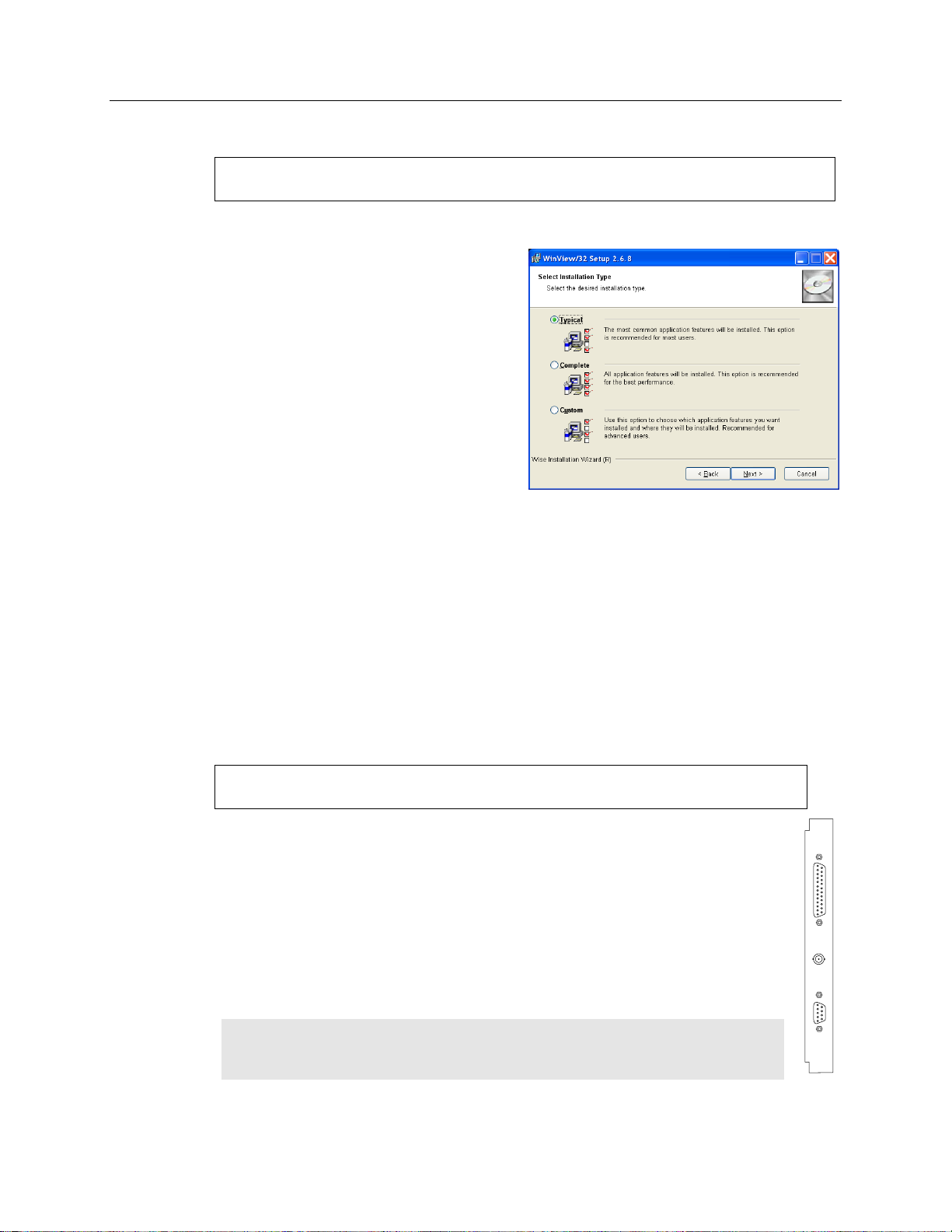
1. Insert the CD and follow the
installation wizard prompts.
2. On the Select Installation Type
dialog (see Figure 5), click on the
Typical radio button to install
the required drivers and the most
commonly installed program
files. Select the Custom radio
button if you would like to
choose among the available
program files or do not want to
install the drivers. Complete
installs all of the application
features.
Figure 5. WinView/32 Installation:
Select Installation Type dialog
A Princeton Instruments (RSPI) PCI card must be installed in the host computer if
the communication between computer and controller uses the TAXI protocol (i.e.,
the Interface Control Module installed in the ST-133 has a 9-pin SERIAL COM
connector as shown in the figure at right). With TAXI protocol, the standard cable
provided with an ST-133 is 7.6 meters (25 feet) and the digitization rate may be
as high as 2 MHz. Cable lengths up to 50 meters (165 feet) are also available.
TTL IN/OUT
AUX
SERIAL COM
A computer purchased from Princeton Instruments will be shipped with the PCI card
already installed. Otherwise, a PCI card will be shipped with the system and you will
have to install it in the host computer at your location.
Note: The PCI card can be installed and operated in any Macintosh having a
PCI bus, allowing the ST-133 to be controlled from the Macintosh via IPLab™
software and the PI Extension.
Installing the WinView/32 Application Software
Administrator privileges are required under Windows® XP, Windows Vista® and
Windows® 7 to install software and hardware.
The following installation is performed via the WinView/32 software installation CD.
3. Verify the camera is connected to the host computer and that the camera power
supply is turned on.
4. Reboot the computer if prompted to do so.
Setting up the Communication Interface
PI-MTE2 camera systems require either an installed Princeton Instruments (RSPI) PCI
card or an installed USB2.0 interface card in the host computer. The type of interface
card is dictated by the Interface Control Module installed in the ST-133 controller.
Setting up a PCI Interface
Administrator privileges are required under Windows® XP, Windows Vista® and
Windows® 7 to install software and hardware.
Page 26

26 PI-MTE System Manual Version 4.C
Windows Version
PCI INF Filename
Located in "Windows"/INF
directory*
PCI Device Driver Name
Located in "Windows"/System32/Drivers
directory
Windows® XP,
Windows Vista®,
and Windows® 7
rspi.inf (in WINNT/INF, for
example)
rspipci.sys (in WINNT/System32/Drivers,
for example)
* The INF directory may be hidden.
CAUTION
If using WinView/32 software, either High Speed PCI or PCI(Timer) can be the selected
Interface type. This selection is accessed on the Hardware Setup|Interface tab page.
High Speed PCI allows data transfer to be interrupt-driven and gives the highest
performance in some situations. PCI(Timer) allows data transfer to be controlled by a
polling timer. This selection is recommended when there are multiple devices sharing the
same interrupt.
To Install a PCI Serial Buffer Card in the Host Computer:
1. Review the documentation for your computer and PCI card before continuing
with this installation.
2. To avoid risk of dangerous electrical shock and damage to the computer, verify
that the computer power is OFF.
3. Remove the computer cover and verify that there is an available PCI slot.
4. Install the PCI card in the slot.
5. Verify that the card is firmly seated and secure it.
6. Replace and secure the computer cover and turn on only the computer. If an error
occurs at bootup, either the PCI card has not been installed properly or there is
an address or interrupt conflict. Refer to Chapter 7 "Troubleshooting", page 71
for instructions.
Note: The PCI card has no user-changeable jumpers or switches.
To Install the PCI Card Driver
The following information assumes that you have already installed the WinView/32
software.
1. After you have secured the PCI card in the computer and replaced the cover, turn
the computer on.
2. At bootup, Windows will try to install the new hardware. If it cannot locate the
driver, you will be prompted to enter the directory path, either by keyboard entry
or by using the browse function.
If you selected AUTO PCI during the application software installation, WinView/32
automatically put the required INF file into the Windows/INF directory and put the
PCI card driver file in the "Windows"/System32/ Drivers directory. Refer to Table 1
below for the appropriate file names and locations.
Table 1. PCI Driver Files and Locations
Page 27

Chapter 4 System Setup 27
TTL
IN/OUT
AUX
USB 2.0
Administrator privileges are required under Windows® XP, Windows Vista®
and Windows® 7 to install software and hardware.
Setting up a USB 2.0 Interface
Your system has been configured to use the USB communication protocol if the
Interface Control Module installed in the ST-133 has a USB 2.0 connector as
shown in the figure at right. The advantages to the USB 2.0 interface are that it uses a
much higher data transfer rate than many common serial data formats (such as the
TAXI protocol) and it simplifies the connection to external devices. USB supports
"plug and play" - you do not need to be heavily involved in the setup process.
USB 2.0 Limitations
Maximum cable length is 5 meters (16.4 feet)
2 MHz is currently the upper digitization rate limit for the ST-133
Controller. Large data sets and/or long acquisition times may be subject
to data overrun because of host computer interrupts during data
acquisition.
USB 2.0 is not supported by the Princeton Instruments PC Interface Library (Easy
DLLS).
Some WinView 2.5.X features are not fully supported with USB 2.0. Refer to
Appendix E, page 95, for more information.
Note: If you are installing the USB 2.0 interface on a laptop, you will need to perform
all of the operations described in this section. In addition, if you are using the
recommended USB Interface Card (SIIG, Inc. USB 2.0 PC Card, Model US2246), you
must replace the OrangeUSB USB 2.0 Host Controller driver installed for that card with
the appropriate Microsoft driver. Instructions for making the replacement are included in
"To Update the OrangeUSB USB 2.0 Driver".
Page 28

28 PI-MTE System Manual Version 4.C
To Update the OrangeUSB USB 2.0 Driver:
This procedure is strongly recommended when a laptop computer will be used to
communicate with the ST-133. As stated before, we recommend the SIIG, Inc. USB 2.0
PC Card, Model US2246 if USB 2.0 is not native to the laptop's motherboard. To reduce
the instances of data overruns and serial violations, the OrangeUSB USB 2.0 Host
Controller installed for the SIIG card, should be replaced with the appropriate Microsoft
driver (Windows XP, Windows Vista, or Windows 7 depending on the laptop's operating
system.)
Note: This procedure may also be performed for desktop computers that use the
Orange Micro 70USB90011 USB2.0 PCI.
1. Download and install Microsoft Service Pack 1 (for Windows XP only) if the service
pack has not been previously installed.
2. From the Windows Start menu, select Settings|Control Panel.
3. Select System and then System Properties.
4. Select the Hardware tab and click on Device Manager button.
5. Expand Universal Serial Bus Controllers.
6. Right-mouse click on OrangeUSB USB 2.0 Host Controller and select
Properties.
7. On the Driver tab, click on the Update Driver… button. You may have to wait a
minute or so before you will be allowed to click on the button.
8. When the Upgrade Device Driver Wizard appears, click on Next. Select the
Search for a suitable driver… radio button.
9. On the next screen select the Specify a location checkbox.
10. Browse and select the location. Click on OK.
11. In the Driver Files Search Results window, check the Install one of the
other drivers check box.
12. Select the NEC PCI to USB Enhanced Host Controller B1 driver. Click on Next
and the installation will take place. When the Completing the Upgrade Device
Driver Wizard window appears, click on Finish. You will then be given the choice
of restarting the computer now or later. According to the window text, the hardware
associated with the driver will not work until you restart the computer.
Page 29

Chapter 4 System Setup 29
The following information assumes that:
You have verified that the host computer meets the required specifications
for USB 2.0 communication with the PI-MTE system (refer to page 23).
A USB 2.0 board and its driver are installed in the host computer.
The ST-133 has an installed USB 2.0 Interface Control module.
You have already installed the WinView/32 software.
Windows
Version
USB INF Filename
Located in
"Windows"/INF
directory*
USB Properties DLL
Located in
"Windows"/
System32 directory
USB Device Driver Name
Located in "Windows"/
System32/ Drivers
directory
Windows® XP,
Windows Vista®,
or Windows® 7
rsusb2k.inf (e.g.,
WINNT/INF)
apausbprop.dll (e.g.,
WINNT/System32)
apausb.sys (e.g.,
WINNT/System32/Drivers)
* The INF directory may be hidden.
To Install the Princeton Instruments USB2 Interface:
1. Before installing the Princeton Instruments USB2 Interface, we recommend that
you defragment the host computer's hard disk. This operation reduces the time the
computer spends locating files. Typically, the "defrag" utility "Disk Defragmenter"
can be accessed from the Windows® Start menu and can usually accessed from the
Programs/Accessories/System Tools subdirectory.
2. After defragmenting the hard disk, turn off the computer and make the USB cable
connections between the host computer and the ST-133. Then, turn the ST-133 on
before turning on the host computer.
3. At bootup, Windows will detect the Princeton Instruments USB2 Interface
hardware (i.e., the USB 2.0 Interface Control module). You may be prompted to
enter the directory path(s) for the apausbprop.dll and/or the apausb.sys file(s),
either by keyboard entry or by using the browse function.
If you selected AUTO PCI during the application software installation,
WinView/32 automatically put the required INF, DLL, and USB driver files in the
"Windows" directories shown below. Refer to the Table 2 for the file locations.
Table 2. USB Driver Files and Locations
Page 30

30 PI-MTE System Manual Version 4.C
CAUTION
Connecting the Interface (Controller-Computer) Cable
TAXI® Cable (6050-0148-CE)
Turn the Controller power OFF (OFF = 0, ON = |) and the Computer power OFF before
connecting or disconnecting the Controller-Computer cable.
To Connect the TAXI Cable:
1. Verify that the Controller power is OFF.
2. Verify that the Computer power is OFF.
3. Connect one end of the TAXI cable to the 9-pin port on the Interface card.
4. Tighten down the screws to lock the connector in place.
5. Connect the other end of the cable to the "Serial Com" port on the rear of the
Controller.
6. Tighten down the screws to lock the connector in place.
USB 2.0 Cable (6050-0494)
Turn the Controller power OFF (OFF = 0, ON = |) and the Computer power OFF before
connecting or disconnecting the Controller-Computer cable.
To Connect the USB 2.0 Cable:
1. Verify that the Controller power is OFF.
2. Verify that the Computer power is OFF.
3. Connect one end of the USB cable to the USB port on the host computer.
4. Connect the other end of the cable to the USB 2.0 port on the rear of the
Controller.
Connecting the Detector-Controller Cable
Non-Vacuum
Follow this procedure if you are using the camera in a non-vacuum environment. When
operating the camera outside of a vacuum, the camera will typically have the visible nose
already installed. If the visible nose is not installed, refer to Appendix D, "Replacing the
Open Nose with the Visible Nose", page 93, for installation instructions.
Turn the Controller power OFF (OFF = 0, ON = |) before connecting or disconnecting
the Detector-Controller cable.
To Connect the Detector-Controller Cable:
The following procedure assumes that you have a cable (such as the 6050-0321) with slide
latches at both ends. If you do not, follow the instructions for Vacuum but do not change the
visible nose to the open nose.
1. Verify that the Controller power is OFF.
2. Connect male end of the Detector-Controller cable to the “Detector” port on the back
of the Controller.
Page 31

Chapter 4 System Setup 31
CAUTION
FRAGILE
3. Move the slide latch over to lock the connector in place. Refer to "Securing the
Detector-Controller Cable Slide Latch", page 76.
4. Connect the female end of the cable to the camera.
5. Slide the latch until it locks on the posts.
Vacuum
Follow this procedure if you are using the camera in a vacuum chamber. Before
operating the camera in a vacuum chamber, you will need to remove the visible nose that
was installed on the camera before it was shipped. Refer to Appendix D, "Replacing the
Visible Nose with the Open Nose", page 91 for more information. Two cables are used
in this procedure: one for inside the vacuum chamber and the other for connection to the
ST-133 outside of the chamber.
Turn the Controller power OFF (OFF = 0, ON = |) before connecting or disconnecting
the Detector-Controller cable.
The 3' long vacuum-compatible cable is fragile and should be handled very carefully to
prevent wire breakage at the connector ends. Never pull on the cable wires when
connecting the cable to or disconnecting it from the cable connectors on the vacuum
flange, or the camera.
To Connect the Detector-Controller Cables:
1. Verify that the Controller power is OFF.
2. Connect male end of the 6' long Detector-Controller cable to the “Detector” port on
the back of the Controller. Use the 3' long Detector-Controller cable if you have a
2 MHz system.
3. Move the slide latch over to lock the connector in place. Refer to "Securing the
Detector-Controller Cable Slide Latch", page 76.
4. Connect the female end of the cable to the vacuum flange.
5. Screw the connector in place.
6. Carefully secure the 3' long vacuum-compatible cable to the inside of the vacuum
flange. Use a 3/32" hex tool to tighten down the screws.
7. Connect the end of the cable with the slide latch to the back of the camera and slide
the latch until it locks on the posts.
Page 32

32 PI-MTE System Manual Version 4.C
Entering the Default Camera System Parameters into WinView
The following instructions assume that you have performed the computer interface
installation.
1. Make sure the ST-133 is connected to the host computer, that it is turned on and that
the computer recognizes the camera peripheral.
2. Run the WinView/32 application. The Camera Detection wizard will
automatically run if this is the first time you have installed a Princeton Instruments
WinView/32 application and a supported camera. Click on the Setup tab and then
select the Hardware function. Then select the “Launch Camera Detection Wizard…”
button in the Controller/Camera tab to start the wizard. Otherwise, if you are
installing a new camera type, click on the Launch Camera Detection Wizard…
button on the Controller/CCD tab to start the wizard.
3. On the Welcome dialog (Figure 6), leave the checkbox unselected and click on
Next.
Figure 6. Camera Detection Wizard - Welcome dialog
4. Follow the instructions on the dialogs to perform the initial hardware setup: this
wizard enters default parameters on the Hardware Setup dialog tabs and gives you
an opportunity to acquire a single test image to confirm the system is working. Note
that this is a test image and it is not acquired using the settings needed for true data
acquisition.
Note: For a step-by-step procedure on basic system operation, refer to the WinView/32
“First Light” section starting on page 37.
Page 33

Chapter 4 System Setup 33
CAUTION
Making the Coolant Connections
1. Take care that the coolant used is pH neutral. Acidic or alkaline coolant can damage
the camera fittings and internal cooling block through corrosion. Such damage could
be very expensive to repair.
2. Coolant should be no colder than +10° C to +15°C to prevent condensation at 50%
relative humidity. Operating the camera with coolant at a colder temperature could cause
induced condensation in the electronics enclosure and possible catastrophic damage to the
camera when the camera is operating outside of a vacuum enclosure. Damage resulting
from this type of operation may void the warranty.
1. Set up the coolant circulator according to the directions in the user manual for that
equipment. Do not apply power to the circulator until directed to do so.
2. Make the hose connections between the camera and the vacuum flange. Stainless
steel flexible hoses (30" long) with female VCR fittings (Swagelok fittings were
provided for earlier systems) are provided to make the connections. Instructions for
VCR fittings and for Swagelok fittings can be found in Appendix C of this manual.
Note: Figure 7 shows the correct coolant ports for the incoming and outgoing
coolant. These ports are NOT INTERCHANGEABLE.
Figure 7. Coolant Ports
3. Set up the coolant circulator according to the directions in the user manual for that
equipment. Do not apply power to the circulator until directed to do so.
4. Make the hose connections between the vacuum flange and the chiller/coolant
circulator. The tubing should be no longer than necessary.
Recommended Flow Rate and Fluid Pressure
Flow Rate: 2 liters/minute. Users are advised to install a flow meter to monitor the
rate.
Fluid Pressure: 25 psig (maximum).
Page 34

34 PI-MTE System Manual Version 4.C
This page intentionally left blank.
Page 35

Chapter 5
WARNING
Operation
Introduction
The PI-MTE camera family has been designed for mobile operation inside a vacuum
chamber. These cameras can be mounted on a movable arm in vacuum to image a subject
from more than one direction. Designed for operation with an ST-133 controller, these
cameras incorporate a two-stage thermoelectric cooler with heat dissipation to circulating
water or other (non-cryogenic) liquid coolant. These cameras can be provided with
vacuum-compatible electrical cabling and coolant hoses and with corresponding
feedthroughs mounted on a vacuum flange. These options provide for connection of the
camera controller and liquid coolant system (outside the vacuum) to the camera head
itself (inside the vacuum). The typical CCD operating temperature for PI-MTE series
cameras extends to -40°C with +15°C circulating coolant; the operating temperature is
somewhat lower with refrigerated coolant. No mechanical shutter is present on these
units.
A two-stage Peltier effect thermoelectric cooler, driven by closed-loop proportionalcontrol circuitry, cools the CCD. A thermal sensor attached to the cooling block of the
camera monitors its temperature.
Two front sections (noses) are available for the PI-MTE camera: an open nose for work
inside a vacuum chamber and a visible nose (with quartz window) for operation in an
atmospheric environment. When the open nose is on the camera, EXTREME caution
must be used to avoid damage to the CCD array. The nose opening should remain
covered when the camera is not in the vacuum chamber. Operation in atmosphere
should NEVER be attempted with the open nose. The CCD array is not protected from
contamination by this nose. It is best not to open this nose except in a cleanroom
environment.
Once the PI-MTE camera has been installed (and optics have been adjusted if the visible
nose is being used), operation of the camera is basically straightforward. In most
applications you simply establish optimum performance using the Focus mode
(WinView/32) and then do actual data acquisition in the Acquire mode. During data
acquisition, the CCD array is exposed to a source and charge accumulates in the pixels.
After the defined exposure time, the accumulated signal is readout of the array, digitized,
and then transferred to the host computer. Upon data transfer, the data is data is
displayed and/or stored via the application software. This sequence is illustrated by the
block diagram shown in Figure 8.
35
Page 36

36 PI-MTE System Manual Version 4.C
Figure 8. Block Diagram of Signal Path in System
Whether or not the data is displayed and/or stored depends on the data collection
operation (Focus or Acquire) that has been selected in the application software. In
WinView, these operations use the Experiment Setup parameters to establish the
exposure time (the period when signal of interest is allowed to accumulate on the CCD).
In Focus mode, the number of frames and accumulations settings are ignored. A
single frame is acquired and displayed, another frame is acquired and overwrites the
currently displayed data, and so on until Stop is selected. No frames of data are
stored. However, when Stop is selected, the File Save function can be used to save
the currently displayed data. This mode is particularly convenient for familiarization
and setting up. For ease in focusing, the screen refresh rate should be as rapid as
possible, achieved by operating with axes and cross-sections off, and with Zoom 1:1
selected.
In Acquire mode, every frame of data collected can be automatically stored (the
completed dataset may include multiple frames with one or more accumulations).
This mode would ordinarily be selected during actual data collection. One limitation
of Acquire mode operation is that if data acquisition continues at too fast a rate for it
to be stored, data overflow will eventually occur. This could only happen in Fast
Mode operation.
The remainder of this chapter is organized to first talk about the system on/off
sequences. Then the "First Light" procedure for imaging applications follows: this
procedure provides step-by-step instruction on how to initially verify system operation.
The last three sections discuss factors that affect exposure, readout, and digitization of
the incoming signal. By understanding these factors and making adjustments to software
settings, you can maximize signal quality. For information about synchronizing data
acquisition with external devices, please refer to Chapter 6, Advanced Topics.
Page 37

Chapter 5 Operation 37
System On/Off Sequences
If your system is configured for the USB 2.0 communication interface, you must follow
the system on/off sequences as stated below. These sequences ensure that
communication is established and maintained between the camera and the host computer:
1. The PI-MTE camera must be powered ON before WinView/32 is opened to ensure
communication between the camera and the computer. If WinView is opened and
the PI-MTE is not powered ON, many of the functions will be disabled and you
will only be able to retrieve and examine previously acquired and stored data. You
must close WinView, power the camera ON, and reopen WinView before you can
set up experiments and acquire new data.
2. WinView/32 must be closed before powering the camera OFF. If you power the
camera OFF before closing WinView, the communication link with the camera will
be broken. You can operate the program in a playback mode (i.e., examine
previously acquired data) but will be unable to acquire new data until you have
closed WinView, powered the camera ON, and then re-opened WinView.
First Light
This section provides step-by-step instructions for acquiring an imaging measurement
outside of a vacuum environment (the visible nose is installed on the camera). The intention
of this procedure is to help you gain basic familiarity with the operation of your system and
to show that it is functioning properly before removing the visible nose and installing the
camera in a vacuum environment. Once basic familiarity has been established, then
operation with other operating configurations, ones with more complex timing modes, can
be performed.
Assumptions
The following procedure assumes that:
1. The camera still has the visible nose installed (the camera is shipped with this
nose) and that you are verifying the camera system operation.
2. You have read Chapter 4 and the previous sections of this chapter.
3. You have made the appropriate cabling and coolant connections for your
system.
4. The system is liquid-cooled.
5. You are familiar with the application software.
6. The system is being operated in imaging mode.
7. The target is a sharp image, text, or a drawing that can be used to verify that the
camera is "seeing" and can be used to maximize focus.
Cabling
If the system cables haven’t been installed, connect them as instructed in Chapter 4.
Page 38

38 PI-MTE System Manual Version 4.C
Getting Started
1. If the system is liquid-cooled, double check that the circulator is filled with a
50:50 mixture of ethylene glycol and water and that the hose connections are
secure. When satisfied that these requirements are met, do the following:
a. Turn on the circulator. The circulator will power up and begin pumping
coolant through the camera. Refer to the circulator instruction manual for
detailed information.
b. Inspect the coolant hose connections to be sure there are no leaks.
c. Turn on the refrigeration, if this feature is available, and set the coolant
temperature (+20°C). The compressor will start and cooldown will begin.
2. Verify that the line-voltage setting of the ST-133 is correct for the available
power and switch ON the ST-133.
3. Block light from the window.
4. Turn on the power at the computer and start the application software
(WinView/32, for example).
Setting the Parameters
Note: The following procedure is based on WinView/32: you will need to modify it
if you are using a different application. Basic familiarity with the WinView/32
software is assumed. If this is not the case, you may want to review the software
manual or have it available while performing this procedure.
Set the software parameters as follows:
Environment dialog (Setup|Environment): Check the DMA Buffer size.
Large arrays (2048 × 2048, for example) require a buffer size on the order of
32 Mbytes. If you change the buffer size, you will have to reboot the
computer for this memory allocation to be activated, and then restart
WinView.
Controller|Camera tab page (Setup|Hardware): Because the Camera
Detection Wizard (Hardware Wizard for earlier software version)
installed default values appropriate for your system, verify the settings on
this page. To reload the defaults, you click on the Load Defaults From
Controller button on this tab page to load the default settings.
Controller type: ST-133
Controller version: 3 or higher
Camera type: Select the array installed in your camera.
Shutter type: None.
Readout mode: Full frame.
Page 39

Chapter 5 Operation 39
Detector Temperature (Setup|Detector Temperature…): +20°C for the
First Light procedure. To see when the array temperature reaches and
stabilizes at the target temperature, leave the Detector Temperature dialog
box open. When the target temperature is reached, the dialog box will report
that the Current Temperature has Locked.
Note: If you are using the USB 2.0 interface, the Detector Temperature
dialog box will not display temperature information while you are acquiring
data.
Interface tab page (Setup|Hardware): High Speed PCI (or PCI(Timer))
Note: This tab page is not available if you are using the USB 2.0 interface.
Cleans and Skips tab page (Setup|Hardware): Default
Experiment Setup Main tab page (Acquisition|Experiment Setup…):
Exposure Time: 100 ms
Accumulations & Number of Images: 1
Experiment Setup ROI tab page (Acquisition|Experiment Setup…):
Use this function to define the region of interest (ROI).
Imaging Mode: Selected
Clicking on Full loads the full size of the chip into the edit boxes.
Experiment Setup Timing tab page (Acquisition|Experiment Setup…):
Timing Mode: Free Run
Shutter Control: Normal
Safe Mode vs. Fast Mode: Safe
Acquiring Data
If you are using WinView/32, select Focus from the Acquisition menu. Successive
images will be sent to the monitor as quickly as they are acquired. Since the camera is
shipped without a shutter, the images may smear if the exposure time is short. Figure 9
shows the kind of data you might see in WinView.
Page 40

40 PI-MTE System Manual Version 4.C
Figure 9. Example of WinView Data Acquired from First Light Procedure
Because the time to acquire and read out an image varies directly with the size of the
CCD, the observed frame rate will vary greatly depending on the CCD installed. With a
short exposure time, it is not uncommon for the frame readout time to be significantly
longer than the exposure time.
This completes First Light. If the system functioned as described, you can be reasonably
sure it has arrived in good working order. In addition, you should have a basic
understanding of how the system hardware is used. A recommended procedure for
powering down the camera is provided in the next section.
After you have powered down the camera system, you can then prepare the camera for
installation in a vacuum chamber. Please follow the instructions provided in "Replacing
the Visible Nose with the Open Nose" on page 91.
Powering Down Procedure
To prevent condensation damage to the camera, it is recommended that camera warm-up
be carefully controlled. Proper warm-up of the camera after operation at temperatures
below ambient is performed as follows.
1. Set the circulator’s refrigeration On/Off switch to OFF.
2. While running WinView, gradually bring the camera temperature up in 10°C steps
from its current lock temperature to ambient temperature. To accomplish this, open
the Detector Temperature dialog box, set the target temperature to 10°C above the
current lock temperature, wait until lock is reached, and then raise it again in 10°C
steps until ambient temperature is reached.
3. After ambient temperature is reached, close WinView and then set the ST-133
Controller’s Power switch to OFF. This will turn off the camera.
4. Set the circulator’s main power switch to OFF.
Page 41

Chapter 5 Operation 41
WARNINGS
WARNING
5. The previous steps should be sufficient to prevent condensation from occurring on
the camera (its array, electronics, and /or coolant ports). However, if the camera is
currently in an evacuated vacuum chamber, you may also want to allow at least
30 minutes to pass before venting the vacuum chamber.
6. This completes the warm-up procedure.
Cooling
Introduction
The PI-MTE cameras were developed for operation inside a vacuum chamber. A twostage Peltier effect device provides the primary CCD cooling and the waste heat is
removed by circulating liquid coolant.
Sustained operation of these cameras without providing liquid cooling will permanently
damage the camera. Such damage is not covered by the Warranty.
PI-MTE cameras are provided with 1/4 tubing fittings (Cajon Ultra-Torr®) for the
circulation of liquid coolant. Use of water/glycol solution (i.e., automotive antifreeze,) is
preferred. Avoid using any corrosive liquid. Set the coolant flow rate to 2 liters/minute. The
temperature of the coolant is usually a compromise among a number of competing factors
including the camera ambient conditions. Princeton Instruments typically uses 10° to 15°C
coolant for testing.
Operated in a vacuum chamber, a standard PI-MTE camera will achieve an array
temperature of -40°C with 15°C coolant. An evacuated camera with the visible nose and
operated in the laboratory atmosphere will achieve an array temperature of -25°C with
15°C coolant.
Condensation
Condensation can cause damage to the camera and will void the warranty. If there are
ANY signs of condensation on the camera's coolant pipes, on the CCD, or on the interior
CCD window (if so equipped), stop operation immediately and contact the factory for
recommended corrective action.
The CCD array and electronics are subject to damage from condensation if exposed to
atmospheric moisture when cold. The following paragraphs discuss condensation risk
factors and their prevention.
Before operating in atmosphere with a PI-MTE camera designed for vacuum chamber
operation, check the temperature and humidity levels. If the conditions are such that
running with chilled coolant will result in condensation, you should only circulate room
temperature coolant through the camera. Condensation damage may occur if the coolant
pipes become cold enough to condense water from the atmosphere or if water condenses
on the CCD array as a result of deterioration of the internal vacuum. At the first sign of
condensation on the coolant pipes or CCD array, turn off the system immediately and
contact the factory for corrective action advice.
Page 42

42 PI-MTE System Manual Version 4.C
WARNING
Operating a PI-MTE with the visible nose in atmosphere can result in condensation if the
camera has not been evacuated to at least 1 mTorr before running with chilled coolant
(coolant should be no colder than +10° C to +15°C to prevent condensation at 50% relative
humidity). Over time the vacuum will degrade, so always evacuate a visible nose camera
before running it in atmosphere. At the first sign of condensation on the coolant pipes
or the CCD array, turn off the system immediately.
An open-nose PI-MTE camera inside a vacuum chamber is subject to condensation if the
chamber is vented too soon after powering off the camera. Failure to turn off the coolant
flow to a camera in a vacuum chamber can also result in condensation when the chamber
is vented. In addition, because vacuum venting can contaminate the cooled surface of the
CCD, we advise you to position a gate valve between the camera and the rest of the
system. This is also highly recommended to prevent contamination.
PI-MTE cameras that use the open nose depend on the vacuum environment for thermal
isolation of the cooled CCD and for preventing condensation on it. Operating these
cameras in air will result in damage to the CCD array. In vacuum chamber operation,
after the camera has been turned off and the coolant flow stopped, the camera should be
allowed to warm up for at least thirty (30) minutes before the vacuum chamber is vented.
To prevent condensation damage while the camera is mounted in the vacuum chamber:
Vacuum Chamber: Make sure that the vacuum chamber has been pumped
down to at least 1 mTorr, before cooling the camera below ambient or turning on
coolant flow.
Camera: Before venting a chamber, turn off the camera, turn off coolant flow,
and allow the camera to warm up for at least thirty (30) minutes. Do not vent
the chamber if coolant is still flowing through the camera.
Exposure and Signal
Introduction
The following topics address factors that can affect the signal acquired on the CCD
array. These factors include array architecture, exposure time, CCD temperature, dark
charge, and saturation.
CCD Array Architecture
Charge coupled devices (CCDs) can be roughly thought of as a two-dimensional grid of
individual photodiodes (called pixels), each connected to its own charge storage “well.”
Each pixel senses the intensity of light falling on its collection area, and stores a
proportional amount of charge in its associated “well.” Once charge accumulates for the
specified exposure time (set in the software), the pixels are read out serially.
Page 43

Chapter 5 Operation 43
Exposure Time
Exposure time (set on the Experiment
Setup|Main tab page) is the time between start
acquisition and stop acquisition commands sent
by the application software to the camera. In
combination with triggers, these commands
control when continuous cleaning of the CCD
stops and when the accumulated signal will be
readout. The continuous cleaning prevents
buildup of dark current and unwanted signal
prior to the x-ray pulse. At the end of the
exposure time, the CCD is readout and cleaning
starts again.
PI-MTE series cameras do not incorporate an
internal shutter. In addition, only full-frame
CCDs (as opposed to frame-transfer CCDs) are
available at this writing*. Because PI-MTE
cameras do not incorporate an internal shutter, some signal may accumulate on the array
while it is being readout. This continuous exposure of the array during readout may
result in some smearing. However, exposures that are significantly longer than the
readout time can be performed without a shutter, as the amount of smearing will be low.
If smearing or other factors require a shutter, the NOT SCAN or the SHUTTER signal at
the ST-133's output can be used to control a customer-supplied external x-ray
shutter. By using one of the signals to synchronize the shutter operation with exposure,
the CCD can be read out in darkness. Alternatively, the x-ray source can be interrupted
elsewhere in the system while readout is taking place.
Temperature Control
Lowering the temperature of the CCD will generally enhance the quality of the acquired
signal. The temperature is set directly from the application software and it takes from 10-20
minutes for the PI-MTE to reach and lock at the set temperature. The TEMP LOCK
indicator on the back of the controller then lights GREEN to indicate that lock has been
achieved (for more information, refer to the "ST-133 Controller" section in Chapter 2).
Application software, such as WinView/32, also provides a temperature-locked indication.
Notes:
1. Temperature regulation does not reach its ultimate stability for at least 30 minutes
after temperature lock is established. Also note that the thermoelectric cooler has no
capability to heat the CCD. These cameras are therefore more thermally stable at
lower temperatures.
2. Because vacuum venting can contaminate the cooled surface of the CCD, we advise
you to position a gate valve between the camera and the rest of the system. This is
also highly recommended to prevent contamination.
*
Please contact your Princeton Instruments representative for special applications or requirements.
Page 44

44 PI-MTE System Manual Version 4.C
WARNINGS
As previously mentioned in the "Cooling" topic, page 41, cooling also means the
possibility of condensation. PI-MTE cameras when operated in the open nose configuration
depend on the vacuum environment for thermal isolation of the cooled CCD and for
preventing condensation on it. Both the CCD array and the camera electronics are subject to
damage from condensation if exposed to atmospheric moisture when cold.
1. Condensation can cause damage to the camera and will void the warranty. If there are
ANY signs of condensation on the camera's coolant pipes or on the CCD array, stop
operation immediately and contact the factory for recommended corrective action.
2. Operating these cameras in air will result in damage to the CCD array.
Condensation can result in catastrophic damage to the camera and is not covered
by the warranty.
Dark Charge
Dark charge (or dark current) is the thermally-induced buildup of charge in the CCD
over time and varies widely from one CCD array to another. This charge integrates in the
pixel wells whenever the camera is on, whether or not data is being acquired, and could
result in the loss of dynamic range. In the case of cameras with MPP type arrays, the
average dark charge is extremely small. However, the dark-charge distribution is such
that a significant number of pixels may exhibit a much higher dark charge, limiting the
maximum practical exposure. Dark charge effect is more pronounced in the case of
cameras having a non-MPP array.
Because dark charge is thermally-induced, reducing the array temperature significantly
reduces the rate at which of dark charge accumulates in the pixel wells. Even so, enough
dark charge could accumulate in the pixels between data acquisitions to affect dynamic
range at the beginning of an exposure. To prevent this from happening, clean cycles
(refer to "Clean Cycles", below) repeatedly shift and discard any signal that has
integrated on the array while waiting for a Start Acquisition command.
After the Start Acquisition command is received by the controller and exposure begins, both
the signal of interest and dark charge integrate on the array. The longer the exposure time and
the warmer the camera, the larger and less uniform the dark charge will appear. To minimize
the dark charge contribution to the acquired signal, you should operate with the lowest
temperature possible for your camera. Reducing the exposure time may also be helpful.
To further reduce the dark charge contribution to an acquired signal, you can perform
background subtraction, which subtracts a dark charge background from raw data acquired
using the same experiment conditions. (Refer to "Background Subtraction", page 49).
Notes:
1. Do not be concerned about either the DC level of this background noise or its
shape unless it is very high, i.e., > 1000 counts with 16 bit A/D. What you see is
not noise. It is a fully subtractable readout pattern. Refer to "Background
Subtraction", page 49, for more information.
2. Offset and excess noise problems are more likely to occur if the controller and
camera were not calibrated and tested as a system at the factory.
Page 45

Chapter 5 Operation 45
CAUTION
If you observe a sudden change in the baseline signal you may have excessive humidity
in the camera's vacuum enclosure. Immediately turn off the controller. Then, contact
Princeton Instruments Customer Support for further instructions. Refer to page 106 for
contact information.
Saturation
When signal levels in some part of the image are very high, charge generated in one pixel
may exceed the “well capacity” of the pixel, spilling over into adjacent pixels in a
process called “blooming.” In this case a more frequent readout is advisable, with signal
averaging to enhance S/N (Signal-to-Noise ratio) accomplished through the software.
For signal levels low enough to be readout-noise limited, longer exposure times, and
therefore longer signal accumulation in the CCD, will improve the S/N ratio approximately
linearly with the length of exposure time. There is, however, a maximum time limit for onchip averaging, determined by either the saturation of the CCD pixels by the signal or the
loss of dynamic range due to the buildup of dark charge in the pixels.
Clean Cycles
As stated before, dark charge integrates on the array whenever the camera is on, whether or
not data acquisition is occurring. To minimize the dark charge and other noise in the pixel
wells when data acquisition is idle, the Clean Cycles function shifts accumulated charge in a
predefined number of rows to the shift register and then discards it.
Clean cycles start when you turn the controller on and a clean pattern is programmed into
the controller. At the end of a cycle, the controller checks to see if a Start Acquisition
command has been received. If it has been received, the user-defined number of cleans
(typically 0) will be then performed before the exposure time starts. If a Start Acquisition
command has not been received, the next clean cycle begins.
The number of rows that are shifted and discarded during a clean cycle are defined in the
application software. The most effective cleaning occurs when the number of rows
equals the number of rows on the CCD. However, you need to keep in mind that a clean
cycle must be completed before a Start Acquisition command will be implemented. The
more rows in a cycle, the greater the delay between the command receipt and the
beginning of an exposure. Because of this timing issue, the number of rows per clean
cycle is usually much smaller than the number of rows on the array.
The timing diagram below is for an experiment set up to acquire three (3) images in
Freerun timing mode with normal shutter operation selected. In this diagram, clean cycles
occur before the first exposure and after the last readout period. They do not need to occur
between exposures since each readout cleans the array before the next exposure starts.
Figure 10. Clean Cycles in Freerun Operation
Page 46

46 PI-MTE System Manual Version 4.C
Introduction
After the exposure time has elapsed, the charge
accumulated in the array pixels needs to be read
out of the array, converted from electrons to
digital format, and transmitted to the application
software where it can be displayed and/or
stored. Readout begins by moving charge from
the CCD image area to the shift register. The
charge in the shift register pixels, which
typically have twice the capacity of the image
pixels, is then shifted into the output node and
then to the output amplifier where the electrons
are grouped as electrons/count. This result
leaves the CCD and goes to the preamplifier
where gain is applied.
Figure 11. Array Terms for a CCD
with a Single Output Amplifier
Note: The start of the exposure is signaled by NOT SCAN going high but will not occur
until the current clean cycle and the additional user-defined number of cleans (typically 0)
have finished. "Number of Cleans" is defined on the Setup|Hardware
Setup|Cleans/Skips tab page. If you enter a value other than "0", you will further delay
the start of the exposure by that number of clean cycles.
Continuous Cleans
The Continuous Cleans function is provided when the start of an exposure is tied to an
external trigger (i.e., the experiment is being run in External Sync timing mode). The
continuous clean cycles are defined by the same parameter values as the standard clean
cycles. The difference is that continuous clean cycles occur between NOT SCAN going
high and External Sync going low. When the External Sync trigger arrives during a
continuous clean cycle, that cycle must be completed before the exposure will begin. In
time critical experiments, the number of rows per clean (set on the Hardware Setup|
Controller/Camera tab page) should be 1 or 2 to minimize the delay. Refer to "External
Sync with Continuous Cleans", page 55 for more information.
Readout
WinView allows you to specify the type of readout (full frame or binned) and the gain
(the number of electrons required to generate an ADU).
Full Frame Readout
In this section, a simple 6 4 pixel CCD is used to demonstrate how charge is shifted
and digitized. Full frame readout, for full frame CCDs, reads out the entire CCD surface
at the same time.
Page 47

Chapter 5 Operation 47
The upper left drawing in Figure 12
represents a CCD after exposure but
before the beginning of readout.
The capital letters represent
different amounts of charge,
including both signal and dark
charge. This section explains
readout at full resolution, where
every pixel is digitized separately.
Readout of the CCD begins with the
simultaneous shifting of all pixels
one row toward the “shift register,”
in this case the row at the top. The
shift register is a single line of
pixels along one edge of the CCD,
not sensitive to light and used for
readout only. Typically the shift
register pixels hold twice as much
charge as the pixels in the imaging
area of the CCD.
After the first row is moved into the
shift register, the charge now in the
Figure 12. Full Frame at Full Resolution
shift register is shifted toward the output node, located at one end of the shift register. As
each value is “emptied” into the output it is digitized. Only after all pixels in the first row
are digitized is the second row moved into the shift register. The order of shifting in our
example is therefore A1, B1, C1, D1, A2, B2, C2, D2, A3, ….
After charge is shifted out of each pixel the remaining charge is zero, meaning that the
array is immediately ready for the next exposure.
A subsection of the CCD can be read out at full resolution, sometimes dramatically
increasing the readout rate while retaining the highest resolution in the region of interest
(ROI). To approximate the readout rate of an ROI, in Equation 2 substitute the x and y
dimensions of the ROI in place of the dimensions of the full CCD. Some overhead time,
however, is required to read out and discard the unwanted pixels.
Binning
Binning is the process of adding the data from adjacent pixels together to form a single
pixel (sometimes called a super pixel), and it can be accomplished in either hardware or
software. Rectangular groups of pixels of any size may be binned together, subject to
some hardware and software limitations.
Hardware Binning
Hardware binning is performed on the CCD array before the signal is read out of the
output amplifier. For signal levels that are readout noise limited this method improves
S/N ratio linearly with the number of pixels grouped together. For signals large enough
to render the camera photon shot noise limited, the S/N ratio improvement is roughly
proportional to the square root of the number of pixels binned.
Page 48

48 PI-MTE System Manual Version 4.C
Binning also reduces readout time and the burden on computer memory, but at the
expense of resolution. Since shift register pixels typically hold only twice as much
charge as image pixels, the binning of large sections may result in saturation and
“blooming”, or spilling of charge back into the image area.
Figure 13 shows an example of 2 2 binning. Each pixel of the image displayed by the
software represents 4 pixels of the CCD array. Rectangular bins of any size are possible.
Figure 13. 2 × 2 Binning for Images
Software Binning
One limitation of hardware binning is that the shift register pixels and the output node are
typically only 2-3 times the size of imaging pixels. Consequently, if the total charge binned
together exceeds the capacity of the shift register or output node, the data will be lost.
This restriction strongly limits the number of pixels that may be binned in cases where there is
a small signal superimposed on a large background, such as signals with a large fluorescence.
Ideally, one would like to bin many pixels to increase the S/N ratio of the weak peaks but this
cannot be done because the fluorescence would quickly saturate the CCD.
The solution is to perform the binning in software. Limited hardware binning may be used
when reading out the CCD. Additional binning is accomplished in software, producing a
result that represents many more photons than was possible using hardware binning.
Software averaging can improve the S/N ratio by as much as the square root of the
number of scans. Unfortunately, with a high number of scans, i.e., above 100, camera 1/f
noise may reduce the actual S/N ratio to slightly below this theoretical value. Also, if the
light source used is photon-flicker limited rather than photon shot-noise limited, this
theoretical signal improvement cannot be fully realized. Again, background subtraction
from the raw data is necessary.
Page 49

Chapter 5 Operation 49
This technique is also useful in high light level experiments, where the camera is again
photon shot-noise limited. Summing multiple pixels in software corresponds to
collecting more photons, and results in a better S/N ratio in the measurement.
Background Subtraction
Each CCD has its own dark charge pattern or background that can be subtracted from the
total acquired signal. By subtracting this background, you can eliminate the dark charge,
which might otherwise hide low-intensity signal.
To set up for background subtraction, set up the experiment conditions for acquiring the
actual image (detector temperature, exposure time, region of interest, timing mode, etc.)
and then, while blocking the incoming signal from the array, acquire a dark charge
“background image” under those conditions. Once the background image is acquired,
save it to disk.
After storing the background to disk, you have two choices for background subtraction:
automatic or post-processing.
Automatic: This approach requires that you activate "Background" and specify the
background filename on the Acquisition| Experiment Setup|Data Corrections
tab page before acquiring an image. When you acquire an image, the specified
background file data will automatically be subtracted from the raw image data before
the corrected data is displayed and is available for storage to disk.
Post-Processing: If you prefer to acquire and preserve the raw image data, make
Digitization
Introduction
After gain has been applied to the signal, the Analog-to-Digital Converter (ADC)
converts that analog information (continuous amplitudes) into a digital data (quantified,
discrete steps) that can be read, displayed, and stored by the application software. The
number of bits per pixel is based on both the hardware and the settings programmed into
the camera through the software (refer to "Readout", page 46).
Factors associated with digitization include the digitization rate and baseline signal.
Depending on the camera model, you may be able change the speed at which digitization
occurs and/or offset the baseline. These factors are discussed in the following
paragraphs.
Digitization Rate
During readout, an analog signal representing the charge of each pixel (or binned group
of pixels) is digitized. The number of bits per pixel is based on both the hardware and the
settings programmed into the camera through the software.
sure that "Background" is not active on the Acquisition|Experiment Setup|Data
Corrections tab page. Then, acquire the image, save the raw image data to disk,
and, via the Image Math function, subtract the background file data from the raw
image data. The subsequent data can then be saved to a separate file.
Page 50

50 PI-MTE System Manual Version 4.C
CAUTION
The ST-133 100 kHz/1 MHz Controller has a single A/D converter that can be run at
either 100 kHz or 1 MHz. The choice of digitization speed is made via the application
software.
The ST-133 2 MHz controller provides six digitization rates (from 50 kHz up to 2 MHz),
providing optimum signal-to-noise ratios at all readout speeds. Because the readout noise
of CCD arrays increases with the readout rate, it is sometimes necessary to trade off
readout speed for high dynamic range. The 2 MHz conversion speed permits the fastest
possible data collection and the 100 kHz or 50 kHz conversion speed is suitable for use
where noise performance is the paramount concern. Switching between the conversion
speeds is completely under software control for total experiment automation.
Note: For the 2 MHz controller, ADC baseline offset levels are preset at the factory and
are not user-adjustable.
ADC Offset
ADC offset (also known as baseline offset) provides another way of dealing with dark
charge (refer to "Dark Charge", page 44). By offsetting the baseline signal, much of the
background is ignored during conversion.
Offsetting the baseline is accomplished by adding a voltage to the signal to bring the A/D
output to a non-zero value, typically 50-100 counts. This offset value ensures that all the
true variation in the signal can really be seen and not lost below the A/D “0” value. Since
the offset is added to the signal, these counts only minimally reduce the range of the
signal from 65535 (16-bit A/D) to a value in the range of 50-100 counts lower.
The ability to shift the baseline depends on the controller used in your system. For
100 kHz/1 MHz controllers, the offset values for the Fast (F) and Slow (S) A/D
converters are preadjusted at the factory but may be adjusted via the Zero Adjustment
potentiometers on the back of the controller. In the case of 2 MHz controllers, the
potentiometers are not present and you cannot change the factory set baseline offsets for
the six digitization speeds: changes to the baseline offsets must be performed at the
factory.
Once you have entered the acquisition parameters, wait for temperature lock to occur and
then wait 30 minutes for the camera temperature to completely stabilize. Then try taking
a few dark charge readings.
Notes:
1. Do not be concerned about either the DC level of this background or its shape unless
it is very high, i.e., >400 counts. What you see is not noise. It is a fully subtractable
readout pattern. Each CCD has its own dark charge pattern, unique to that particular
device. Every device has been thoroughly tested to ensure its compliance with
Princeton Instruments' demanding specifications.
2. Do not adjust the offset values to zero or some low-level data will be missed.
If you observe a sudden change in the baseline signal, TURN OFF THE SYSTEM
IMMEDIATELY and contact the factory Customer Support Department. Refer to page
102 for contact information.
Page 51

Chapter 6
Previous chapters have discussed setting up the
hardware and the software for basic operation.
This chapter discusses topics associated with
experiment synchronization (set up on the
Experiment Setup|Timing tab page in
WinView).With the exception of Edge Trigger, the
topics are addressed in order of their appearance on
the Timing tab page (see Figure 14).
"Timing Modes", the first topic, discusses
Timing Modes, Shutter Control, and Edge
Trigger. Also included under this topic is a
discussion of the EXT SYNC connector, the
input connector for a trigger pulse.
"Fast and Safe Modes", the second topic,
discusses the Fast and the Safe speed modes.
Fast is used for real-time data acquisition and
Safe is used when coordinating acquisition with
external devices or when the computer speed is
Figure 14. Timing tab page
The chart to the right lists the timing mode
combinations (selected on the Experiment
Setup|Timing tab page). Use this chart in
combination with the detailed descriptions in
this chapter to determine the optimal timing
configuration.
The basic ST-133 timing modes are Free
Run, External Sync, and External Sync with
Continuous Cleans. These modes are
combined with the Shutter options to provide
the widest variety of timing modes for
precision experiment synchronization.
Mode
Shutter
Free Run
Normal
External Sync
Normal
External Sync
PreOpen
External Sync with
Continuous Cleans
Normal
External Sync with
Continuous Cleans
PreOpen
Table 3. Camera Timing Modes
Advanced Topics
Introduction
not fast enough to keep pace with the acquisition rate.
"TTL Control", the final topic, discusses the TTL IN/OUT connector on the rear of the
ST-133 and how commands can be sent via TTL levels to and from the ST-133.
Standard Timing Modes
51
Page 52

52 PI-MTE System Manual Version 4.C
In the Free Run mode the controller does not
synchronize with the experiment in any way. The
shutter opens as soon as the previous readout is
complete, and remains open for the exposure time,
t
exp
. Any External Sync signals are ignored. This
mode is useful for experiments with a constant light
source, such as a CW laser or a DC lamp. Other
experiments that can utilize this mode are high
repetition studies, where the number of shots that
occur during a single shutter cycle is so large that it
appears to be continuous illumination.
Other experimental equipment can be synchronized to
the ST-133 controller by using the output signal
(software-selectable SHUTTER or NOT SCAN* on
the Hardware Setup|Controller Camera tab page)
from the connector. Shutter operation and the
NOT SCAN output signal are shown in Figure 16.
Shutter opens
Shutter remains open
for preprogrammed
exposure time
System waits while
shutter closes
Figure 15. Free Run Timing Chart,
Part of the Chart in Figure 21
Note: Since PI-MTE cameras do not use shutters, the Shutter Type selection on the
Hardware Setup|Controller/Camera tab page should be "None".
The shutter options available include Normal, PreOpen, Disable Opened or Disable
Closed. Disable simply means that the shutter will not operate during the experiment.
Disable closed is useful for making dark charge measurements or when no shutter is
present. PreOpen, available in the External Sync and External Sync with Continuous
Cleans modes, opens the shutter as soon as the ST-133 is ready to receive an External
Sync pulse. This is required if the time between the External Sync pulse and the event is
less than a few milliseconds, the time it takes the shutter to open.
The shutter timing is shown in the timing diagrams that follow. Except for Free Run,
where the modes of shutter operation are identical, both Normal and PreOpen lines are
shown in the timing diagrams and flow chart.
The timing diagrams are labeled indicating the exposure time (t
compensation time (tc), and readout time (tR). Note that if there is no shutter selected in
the software, the shutter compensation time (the time required to close a mechanical
shutter) will be approximately 0 ms. For more information about these parameters, refer
to the discussion of full frame readout, starting on page 46.
Free Run
*
NOT SCAN reports when the controller is finished reading out the CCD array. NOT SCAN is
high when the CCD array is not being scanned, then drops low when readout begins, returning to
high when the process is finished. The second signal, SHUTTER, reports when the shutter is
opened and can be used to synchronize external shutters. SHUTTER is low when the shutter is
closed and goes high when the shutter is activated, dropping low again after the shutter closes.
), shutter
exp
Page 53

Chapter 6 Advanced Topics 53
Figure 16. Free Run Timing Diagram
External Sync
In this mode all exposures are synchronized to an external source via signal input to the
Ext Sync BNC on the back of the ST-133. To ensure synchronization, the trigger edge
(negative- or positive-going) of the Ext Sync signal must be identified in the application
software (in WinView, this is done on the Experiment Setup|Timing tab page). As
shown in the flowchart, Figure 17, External Sync mode can be used in combination with
Normal or PreOpen Shutter operation. In Normal Shutter mode, the controller waits for
an External Sync pulse, then opens the shutter for the programmed exposure period. As
soon as the exposure is complete, the shutter closes and the CCD array is read out.
Because the external shutter requires a finite amount of time to open completely (shutter
open time may be 5-28 msec depending on the shutter), the External Sync pulse trigger
edge provided by the experiment should precede the actual signal by at least that much
time. If not, the shutter will not be open for the duration of the entire signal, or the signal
may be missed completely.
Also, since the amount of time from initialization of the experiment to the first External
Sync pulse trigger edge is not fixed, an accurate background subtraction may not be
possible for the first readout. In multiple-shot experiments this is easily overcome by
simply discarding the first frame.
In the PreOpen Shutter mode, on the other hand, shutter operation is only partially
synchronized to the experiment. As soon as the controller is ready to collect data, the
shutter opens. Upon arrival of the first External Sync pulse trigger edge at the ST-133,
the shutter remains open for the specified exposure period, closes, and the CCD is read
out. As soon as readout is complete, the shutter reopens and waits for the next frame.
Page 54

54 PI-MTE System Manual Version 4.C
Shutter opens
Shutter remains open
for preprogrammed
exposure time
System waits while
shutter closes
Shutter opens
Controller waits for
External Sync pulse
Controller waits for
External Sync pulse
(shutter preopen) (shutter normal)
Figure 17. Chart Showing Two External Sync Timing Options
The PreOpen mode is useful in cases where an External Sync pulse trigger edge cannot
be provided 5–28 msec (shutter open time) before the actual signal occurs. Its main
drawback is that the CCD is exposed to any ambient light while the shutter is open
between frames. If this ambient light is constant, and the triggers occur at regular
intervals, this background can also be subtracted, providing that it does not saturate the
CCD. As with the Normal Shutter mode, accurate background subtraction may not be
possible for the first frame.
Also note that, in addition to signal from ambient light, dark charge accumulates during
the “wait” time (t
). Any variation in the external sync frequency also affects the amount
w
of dark charge, even if light is not falling on the CCD during this time.
Note: If EXT SYNC is still active (in Figure 18, this means that if it is still LOW) at the
end of the readout, the hardware may interpret this as a second sync pulse, and so on.
Figure 18. Timing Diagram for External Sync Mode (- edge trigger)
Page 55

Chapter 6 Advanced Topics 55
Shutter opens
Shutter remains open
for preprogrammed
exposure time
System waits while
shutter closes
Shutter opens
CCD is continuously
cleaned until External Sync
pulse is received
(shutter preopen) (shutter normal)
CCD is continuously
cleaned until External Sync
pulse is received
External Sync with Continuous Cleans
Another timing mode available with the ST-133 controller is called Continuous Cleans.
In addition to the standard "cleaning" of the array, which occurs after the controller is
enabled, Continuous Cleans will remove any charge that integrates on the array between
the time that the Start Acquisition command is received by the controller and the moment
that the External Sync pulse trigger edge is received.
Figure 19. Continuous Cleans Operation Flowchart
Once the External Sync pulse trigger edge is received, cleaning of the array stops as soon
as the current row is shifted, and frame collection begins: a delay time of up to one row
shift can be expected. With Normal Shutter operation the shutter is opened for the set
exposure time. With PreOpen Shutter operation the shutter is open during the continuous
cleaning, and once the External Sync pulse trigger edge is received the shutter remains
open for the set exposure time, then closes. If the vertical rows are shifted midway when
the External Sync pulse trigger edge arrives, the pulse is saved until the row shifting is
completed, to prevent the CCD from getting “out of step.” As expected, the response
latency is on the order of one vertical shift time, from 1-30 sec depending on the array.
This latency does not prevent the incoming signal from being detected, since photo
generated electrons are still collected over the entire active area. However, if the signal
arrival is coincident with the vertical shifting, image smearing of up to one pixel is
possible. The amount of smearing is a function of the signal duration compared to the
single vertical shift time.
Note: If EXT SYNC is still active (in Figure 20, this means that if it is still LOW) at the
end of the readout, the hardware may interpret this as a second sync pulse, and so on.
Page 56

56 PI-MTE System Manual Version 4.C
Figure 20. Continuous Cleans Timing Diagram (- edge trigger)
Figure 20 shows the same timing diagram as Figure 18 with the addition of continuous
cleans (indicated by the shaded areas labeled CC). Continuous cleans are additional
clean cycles and defined by the same parameter values as the standard clean cycles.
Fast and Safe Modes
The WinView Experiment Setup|Timing tab page allows you to choose Fast Mode or
Safe Mode. Figure 21 is a flow chart comparing the two modes. In Fast Mode operation, the
ST-133 runs according to the timing of the experiment, with no interruptions from the
computer. In Safe Mode operation, the computer processes each frame as it is received. The
ST-133 cannot collect the next frame until the previous frame has been completely processed.
Fast Mode operation is primarily for collecting “real-time” sequences of experimental data,
where timing is critical and events cannot be missed. Once the ST-133 is sent the Start
Acquisition command by the computer, all frames are collected without further intervention
from the computer. The advantage of this triggering mode is that timing is controlled
completely through hardware. A drawback to this mode is that the computer will only
display frames when it is not performing other tasks. Image display has a lower priority, so
the image on the screen may lag several images behind. A video monitor connected to the
VIDEO output will always display the current image. A second drawback is that a data
overrun may occur if the number of images collected exceeds the amount of allocated
RAM or if the computer cannot keep up with the data rate.
Safe Mode operation is primarily useful for experiment setup, including alignment and
focusing, when it is necessary to have the most current image displayed on the screen. It
is also useful when data collection must be coordinated through software with external
devices such as external shutters and filter wheels. As seen in Figure 21, in Safe Mode
operation, the computer controls when each frame is taken. After each frame is received,
the computer sends the Stop Acquisition command to the camera, instructing it to stop
acquisition. Once that frame is completely processed and displayed, another Start
Acquisition command is sent from the computer to the camera, allowing it to take the
next frame. Display is therefore, at most, only one frame behind the actual data
collection.
One disadvantage of the Safe Mode is that events may be missed during the experiment,
since the ST-133 is disabled for a short time after each frame.
Page 57

Chapter 6 Advanced Topics 57
Figure 21. Chart of Safe Mode and Fast Mode Operation
Page 58

58 PI-MTE System Manual Version 4.C
TTL IN
Value
TTL IN
Value
1
1 5
16 2 2 6
32 3 4 7
64 4 8 8
128
TTL IN
Value
TTL IN
Value
1
High (1)
5 Low (0)
2
High (2)
6 Low (0)
3
Low (0)
7 Low (0)
4
Low (0)
8 Low (0)
TTL Control
Fully supported by WinView/WinSpec Version 2.6.x when the communication protocol
is TAXI (PCI). This feature is not supported when the protocol is USB 2.0.
Introduction
Princeton Instruments' WinView and WinSpec software packages incorporates WinX32
Automation, a programming language that can be used to automate performing a variety
of data acquisition and data processing functions, including use of the TTL In/Out
functions. WinX32 Automation can be implemented in programs written in Visual Basic
or Visual C++. Refer to the WinX32 documentation for more detailed information.
The TTL lines are made available through the TTL In/Out connector on the rear of the
ST-133 Controller. This connector provides 8 TTL lines in, 8 TTL lines out and an
input control line. Figure 22 illustrates the connector and Table 5 lists the signal/pin
assignments.
TTL In
The user controls the 8 TTL Input lines, setting them high (+5 V; TTL 1) or low (0 V;
TTL 0). When the lines are read, the combination of highs and lows read defines a
decimal number which the computer can use to make a decision and initiate actions as
specified in the user’s program. If a TTL IN line is low, its numeric value is 0. If a TTL
IN line is high, its numeric value is as follows.
This coding allows any decimal value from 0 to 255 to be defined. Thus, as many as 256
different sets of conditions can be specified, at the user’s discretion, using the TTL IN
lines. Any unused lines will default to TTL high (+5 V). For example, to define the
number three, the user would simply set the lines TTL IN 1 and TTL IN 2 both high
(+5 V). It would be necessary to apply TTL low to the remaining six lines because they
would otherwise default to TTL high as well.
Page 59

Chapter 6 Advanced Topics 59
Decimal
Equiv.
TTL
IN/OUT 8
1= dec 128
TTL
IN/OUT 7
1=dec 64
TTL
IN/OUT 6
1=dec 32
TTL
IN/OUT 5
1=dec 16
TTL
IN/OUT 4
1=dec 8
TTL
IN/OUT 3
1=dec 4
TTL
IN/OUT 2
1=dec 2
TTL
IN/OUT 1
1=dec 1
0 0 0 0 0 0 0 0 0 1 0 0 0 0 0 0 0 1 2 0 0 0 0 0 0 1 0 3 0 0 0 0 0 0 1 1 4 0 0 0 0 0 1 0 0 5 0 0 0 0 0 1 0 1 6 0 0 0 0 0 1 1 0 7 0 0 0 0 0 1 1
1
Table 4 illustrates this coding for decimal values 0 through 7. Obviously this table could
easily be extended to show the coding for values all the way to 255.
Table 4. Bit Values with Decimal Equivalents:
1 = High,
0 = Low
Buffered vs. Latched Inputs
In controlling the TTL IN lines, users also have the choice of two input-line states,
buffered or latched. In the buffered state, the line levels must remain at the intended
levels until they are read. With reference to the preceding example, the high level at TTL
IN 1 and TTL IN 2 would have to be maintained until the lines are read. In the latched
state, the applied levels continue to be available until read, even if they should change at
the TTL In/Out connector.
This control is accomplished using the EN/CLK TTL input (pin 6). If EN/CLK is open
or high, buffered operation is established and the levels reported to the macro will be
those in effect when the READ is made. With reference to our example, if pin 6 were left
unconnected or a TTL high applied, TTL IN 1 and TTL IN 2 would have to be held high
until read. If, on the other hand, EN/CLK were made to go low while TTL IN 1 and TTL
IN 2 were high, those values would be latched for as long as EN/CLK remained low. The
levels actually present at TTL IN 1 and TTL IN 2 could then change without changing
the value that would be read by software.
TTL Out
The state of the TTL OUT lines is set from WinView/32 (or WinSpec/32). Typically, a
program (for example, a macro) monitoring the experiment sets one or more of the TTL
Outputs. Apparatus external to the PI-MTE system interrogates the lines and, on detecting
the specified logic levels, takes the action appropriate to the detected condition. The
coding is the same as for the input lines. There are eight output lines, each of which can
be set low (0) or high (1). The combination of states defines a decimal number as
previously described for the TTL IN lines.
Page 60

60 PI-MTE System Manual Version 4.C
Figure 23. TTL Diagnostics dialog box
Pin #
Assignment
Pin #
Assignment
Figure 22. TTL In/Out
Connector
1
IN 1
14
IN 2
2
IN 3
15
IN 4
3
IN 5
16
IN 6
4
IN 7
17
IN 8
5
GND
18
GND
6
EN/CLK
19
Reserved
7
(future use)
20
GND
8
GND
21
OUT 2
9
OUT 1
22
OUT 4
10
OUT 3
23
OUT 6
11
OUT 5
24
OUT 8
12
OUT 7
25
GND
13
Reserved
Table 5. TTL In/Out Connector Pinout
TTL Diagnostics Screen
Note that WinView/32 provides a TTL
Diagnostics screen (located in WinView/32 under
Hardware Setup - Diagnostics) that can be used
to test and analyze the TTL In/Out lines.
Hardware Interface
A cable will be needed to connect the TTL In/Out
connector to the experiment. The design will vary
widely according to each user’s needs, but a
standard 25-pin female type D-subminiature
connector will be needed to mate with the TTL
In/Out connector on the back of the ST-133. The
hardware at the other end of the cable will depend
entirely on the user’s requirements. If the
individual connections are made using coaxial
cable for maximum noise immunity
(recommended), the center conductor of the coax should connect to the proper signal pin
and the cable shield should connect to the nearest available ground (grounds are
conveniently provided at pins 5, 8, 18 and 20).
Page 61

Chapter 6 Advanced Topics 61
Connector hardware and cables of many different types are widely available and can
often be obtained locally, such as at a nearby Radio Shack® store. A list of possibly
useful items follows. Note that, although the items listed may be appropriate in many
situations, they might not meet your specific needs.
25-pin female type D-subminiature solder type connector (Radio Shack® part no
276-1548B).
RG/58U coaxial cable.
Shielded Metalized hood (Radio Shack part no 276-1536A).
BNC connector(s) type UG-88 Male BNC connector (Radio Shack part no 278-103).
Example
Suppose you needed to build a cable to monitor the line TTL OUT 1. One approach
would be to build a cable assembly as described in the following paragraphs. This
procedure could easily be adapted to other situations.
1. Begin with a 25-pin female type D-subminiature solder type connector (Radio Shack
part no 276-1548B). This connector has 25 solder points open on the back.
2. Referring to Table 5, note that pin 8 = GND and pin 9 = TTL OUT 1.
3. Using coaxial cable type RG/58U (6 feet length), strip out the end and solder the
outer sheath to pin 8 (GND) and the inner line to pin 9 (TTL OUT 1). Then apply
shielding to the lines to insulate them.
4. Mount the connector in a Shielded Metalized hood (Radio Shack part no
276-1536A).
5. Build up the cable (you can use electrical tape) to where the strain relief clamp
holds.
6. Connect a BNC connector (UG-88 Male BNC connector) to the free end of the cable
following the instructions supplied by Radio Shack on the box (Radio Shack part no
278-103).
7. To use this cable, connect the DB-25 to the TTL In/Out connector on the back of the
ST-133.
8. To check the cable, start WinView/32 and open the TTL Diagnostics screen (located
in WinView under Hardware Setup - Diagnostics). Click the Write radio button.
Then click the Output Line 1 box. Next click the OK button to actually set TTL
OUT 1 high. Once you set the voltage, it stays until you send a new command.
9. Measure the voltage at the BNC connector with a standard voltmeter (red on the
central pin, black on the surrounding shielding). Before clicking OK at the TTL
Diagnostics screen you should read 0 V. After clicking OK you should read +5 V.
Note that adding a second length of coaxial cable and another BNC connector would be
straightforward. However, as you increase the number of lines to be monitored, it
becomes more convenient to consider using a multiple conductor shielded cable rather
than individual coaxial cables.
Page 62

62 PI-MTE System Manual Version 4.C
This page intentionally left blank.
Page 63

Chapter 7
Baseline Signal Suddenly Changes
Page 64
Camera1 (or similar name) on Hardware Setup dialog box
Page 64
Changing the ST-133 Line Voltage and Fuses
Page 64
Controller Is Not Responding
Page 67
Cooling Troubleshooting
Page 67
Data Loss or Serial Violation
Page 69
Data Overrun Due to Hardware Conflict
Page 69
Data Overrun Occurred
Page 70
Error Creating Controller message
Page 70
Error Occurs at Computer Powerup
Page 71
Program Error
Page 73
Removing/Installing a Plug-In Module
Page 74
Securing the Detector-Controller Cable Slide Latch
Page 76
Serial violations have occurred. Check interface cable.
Page 77
WARNING!
Troubleshooting
Do not attach or remove any cables while the detector system is powered on.
Introduction
The following issues have corresponding troubleshooting sections in this chapter.
63
Page 64

64 PI-MTE System Manual Version 4.C
Baseline Signal Suddenly Changes
In-Vacuum Operation: If you observe a sudden change in the baseline signal, turn off
the controller. Contact the factory Customer Support Dept. for further instructions. Refer
to page 102 for contact information.
Out-of-Vacuum Operation: If you observe a sudden change in the baseline signal, you may
have excessive humidity in the vacuum enclosure of the camera. Turn off the controller and
have the camera repumped before resuming normal operation. Contact the factory Customer
Support Dept. for further instructions. Refer to page 102 for contact information.
Camera1 (or similar name) on Hardware Setup dialog box
When a PVCAM-based camera is detected/selected during the Camera Detection wizard,
a default name (e.g., Camera1,) will be shown in the Detected Hardware table and will
be entered in the Camera Name field on the Setup|Hardware|Controller/CCD tab as
well as in the Hardware Setup title bar. See Figure 24.
Figure 24. Camera1 in Controller Type (Camera Name) Field
Because this name is not particularly descriptive, you may want to change it. Such a
change is made by editing the PVCAM.INI file that is generated by Camera Detection
wizard.
To change the default Camera Name:
1. Close WinView if it is running.
2. Using Notepad or a similar text editor, open PVCAM.INI, which is located in
the Windows directory (C:\WINDOWS, for example).
3. Edit the Name field.
Page 65

Chapter 7 Troubleshooting 65
Input
Voltage
Fuses
Type
Left
Right
100/120 VAC
0.75 A
2.50 A
Slow Blow
220/240 VAC
0.30 A
1.25 A
Slow Blow
WARNING!
4. Save the edited file.
5. The next time you start WinView, the new name will be displayed on the
Hardware Setup dialog.
6. If you later re-run the Camera Detection Wizard, the name will be changed back
to the default name (i.e., Camera1.)
Changing the ST-133 Line Voltage and Fuses
The appropriate voltage setting for your country is set at the factory and can be seen on
the power module. If your voltage source changes, you will need to change the voltage
setting and you may need to change the fuse configuration.
Table 6. Fuse Ratings
Use proper fuse values and types for the controller and detector to be properly protected.
Page 66

66 PI-MTE System Manual Version 4.C
1. Verify that the power supply is turned
OFF and the power cord is unplugged.
2. As shown in Figure 25, place the flat
side of a flat bladed screwdriver
parallel to the back of the Controller
and behind the small tab at the top of
the power module, and twist the
screwdriver slowly but firmly to pop
the module open.
120V ac
~
Figure 25. Power Module
Figure 26. Voltage Selector Drum
Figure 27. Fuse Holder
3. To change the voltage setting, roll the
selector drum until the setting that is
closest to the actual line voltage is
facing outwards.
4. Turn the drum to the desired voltage
and put the drum back into the module
with that setting facing straight out of
the module.
5. Confirm the fuse ratings by removing the
two white fuse holders. To do so, simply
insert the flat blade of the screwdriver
behind the front tab of each fuse holder
and gently pry the assembly out.
6. Refer to Table 6 or the Fuse/Voltage label (above or below the Power Module) to
determine which fuses are required by the selected voltage. If the Controller power switch
is on the back of the ST-133, the Fuse/Voltage label is located below the Power Module.
7. After inspecting and, if necessary, changing the fuses to those required by
the selected voltage, reinstall the holders with the arrow facing to the
right.
8. Close the power module and verify that the correct voltage setting is
displayed. For example, if you wanted 220 VAC, you should see 220 Vac
in the window.
9. Verify that the Controller power switch is in the OFF position and then plug the
power cord back into the power module.
WARNING!
To Change Voltage and Fuse Configuration:
Before opening the power module, turn the Controller OFF and unplug the power cord.
Page 67

Chapter 7 Troubleshooting 67
Controller Is Not Responding
If this message pops up when you click on OK after selecting the Interface Type during
Hardware Setup (under the WinView/32 Setup menu), the system has not been able
to communicate with the Controller. Check to see if the Controller has been turned ON
and if the interface card, its driver, and the interface cable have been installed.
If the Controller is ON, the problem may be with the interface card, its driver,
interrupt or address conflicts, or the cable connections.
If the interface card is not installed, close WinView/32 and turn the Controller
OFF. Follow the interface card installation instructions in Chapter 4 and cable
the interface card to the SERIAL COM port on the rear of the Controller. Then
do a "Custom" installation of WinView with the appropriate interface
component selected: "PCI Interface". Be sure to deselect any interface
component that does not apply to your system.
If the interface card is installed in the computer and is cabled to the SERIAL
COM port on the rear of the Controller, close WinView and turn the Controller
OFF. Check the cable connections and tighten the locking screws if the
connections are loose.
If the interface card was installed after WinView has been installed, close WinView
and do a "Custom" installation of WinView with the appropriate interface component
selected: "PCI Interface". Be sure to deselect any interface component that does not
apply to your system.
Cooling Troubleshooting
Camera does not achieve temperature lock
If the indicator does not turn green after 30 minutes:
The temperature setting may be at a temperature colder than the specified limit
or the environment could be particularly warm. If this occurs, try a higher
temperature setting. Make sure you are selecting a temperature that is
acceptable for your particular camera and CCD array.
The coolant may not be flowing fast enough. Check the coolant flow rate.
Out-of-Vacuum Operation Cooling and Internal Vacuum Level
With time, there may be a gradual deterioration of the camera’s vacuum. This may affect
temperature performance and it may no longer be possible to achieve temperature lock at
the lowest temperatures. In the kind of low-light imaging applications for which cooled
CCD cameras are so well suited, it is highly desirable to maintain the system’s
temperature performance because lower temperatures provide less thermal noise and
better signal-to-noise ratio.
Page 68

68 PI-MTE System Manual Version 4.C
WARNING
If your PI-MTE is designed for in-vacuum applications: Vacuum deterioration is
normal for PI-MTE cameras that are designed for operation in vacuum chambers but are
temporarily being operated with a visible nose in air. The elastomer gasket between the
nose and the middle enclosure is not intended to provide a permanent vacuum. If you
have the appropriate equipment and personnel with the necessary expertise available,
you may pump down the camera at your facility (refer to steps 12-18 on page 94).
If your PI-MTE is designed for out-of-vacuum applications: The camera will have an
Indium seal between the nose and the middle enclosure. If you have the appropriate
equipment and personnel with the necessary expertise available, you may pump down the
camera at your facility (refer to steps 12-18 on page 94).
The CCD array is subject to damage from condensation if exposed to the atmosphere
when cold. For this reason, the camera should be kept properly evacuated or backfilled
with dry nitrogen, free of oil or other contaminants.
Camera loses temperature lock
The internal temperature of the camera is too high. This might occur if:
The operating environment is particularly warm.
You are attempting to operate at a temperature colder than the specified limit.
The coolant flow is insufficient.
If the camera loses temperature lock, an internal thermal overload switch will
disable the cooler circuits to protect them. Typically, camera operation is
restored in about ten minutes. Although the thermal overload switch will protect
the camera, users are advised to power down and correct the operating
conditions that caused the thermal overload to occur. With some versions of the
software, the indicated temperature when the camera is in thermal overload
(thermal switch is in the cut-out state) is -100° C.
Note: If the Detector Temperature dialog box is open, the following message will be
displayed in the box when thermal overload is detected: "Detector Overheated! Consult
operations manual or contact PI Technical Support if problem persists."
Page 69

Chapter 7 Troubleshooting 69
Data Loss or Serial Violation
You may experience either or both of these conditions if the host computer has been set
up with Power Saving features enabled. This is particularly true for power saving with
regard to the hard drive. Make sure that Power Saving features are disabled while you
are running WinView/32.
Data Overrun Due to Hardware Conflict
Figure 28. Data Overrun Due to Hardware Conflict dialog box
If this dialog box appears when you try to acquire a test image, acquire data, or run in
focus mode, check the CCD array size and then check the DMA buffer size. A large
array (for example, a 2048 × 2048 array), requires a larger DMA buffer larger setting
than that for a smaller array (for example, a 512x512 array).
To change the DMA buffer setting:
1. Note the array size (on the Setup|Hardware|Controller/CCD tab page or the
Acquisition|Experiment Setup|Main tab page Full Chip dimensions).
2. Open Setup|Environment|Environment dialog box.
3. Increase the DMA buffer size to a minimum of 32 Mb (64 Mb if it is currently
32 Mb or 128 Mb if it is currently 64 Mb), click on OK, and close WinView.
4. Reboot your computer.
5. Restart WinView and begin acquiring data or focusing. If you see the message
again, increase the DMA buffer size.
Page 70

70 PI-MTE System Manual Version 4.C
Data Overrun Occurred
Because of memory constraints and the way that USB transfers data, a "Data overrun has
occurred" message may be displayed during data acquisition. If this message is
displayed, perform one or more of the following actions:
1. Minimize the number of programs running in the background while you are
acquiring data with WinView/32.
2. Run data acquisition in Safe Mode.
3. Add memory.
4. Use binning.
5. Increase the exposure time.
6. Defragment the hard disk.
7. Update the Orange Micro USB2 driver. Refer to "To Update the OrangeUSB
USB 2.0 Driver", page 28.
If the problem persists, your application may be USB 2.0 bus limited. Since the host computer
controls the USB 2.0 bus, there may be situations where the host computer interrupts the USB
2.0 port. In most cases, you will not notice the interrupt. However, there are some instances
when the data overrun cannot be overcome because USB 2.0 bus limitations combined with
long data acquisition times and/or large data sets increase the possibility of an interrupt while
data is being acquired. If your experiment requirements include long data acquisition times
and/or large data sets, your application may not be suitable for the USB 2.0 interface.
Therefore, we recommend replacement of the USB 2.0 interface module with our TAXI
interface module and Princeton Instruments (RSPI) PCI card. If this is not the case and data
overruns continue to occur, contact Customer Support (refer to page 102 for contact
information).
Error Creating Controller message
This message may be displayed if you are using the USB 2.0 interface and have not run
the RSConfig.exe program, if the PVCAM.INI file has been corrupted, or if the ST-133
was not turned on before launching WinView/32 and running the Hardware Wizard.
Figure 29. Error Creating Controller dialog box
Error 129: Indicates the problem is with the PVCAM.INI file. Close WinView/32, run
RSConfig, verify the ST-133 is on, reopen WinView, and run the Hardware Wizard.
Error 183: Indicates that the ST-133 is off. If you are running the Hardware Wizard
when this message appears, click on OK, turn on the ST-133, and, on the PVCAM
dialog box, verify Yes is selected, and then click on Next. The Hardware Wizard
should proceed to the Controller Type dialog box.
Page 71

Chapter 7 Troubleshooting 71
Slot Type
Status
I/O Address
Interrupt
1 (ISA)
ISA Network Card
200-210
11
2 (PCI)
PCI Video Card
FF00-FFFF
15
3 (ISA)
ISA Sound Card
300-304
9
4 (PCI)
Empty
N/A
N/A
CAUTION
Error Occurs at Computer Powerup
If an error occurs at boot up, either the Interface is not installed properly or there is an
address or interrupt conflict. Turn off the computer, try a new address or interrupt and
reinstall the card. Be sure the Interface card is firmly mounted in the slot.
Since interrupts and DMA channels cannot be shared, make sure no other boards in your
computer use this interrupt or these DMA channels.
Conflicts
One of the many advantages that PCI offers over ISA is that the whole issue of address and
interrupt assignments is user transparent and under BIOS control. As a result, users
typically do not have to be concerned about jumpers or switches when installing a PCI
card. Nothing more should be required than to plug in the card, make the connections, and
operate the system. As it turns out, however, in certain situations conflicts may nevertheless
occur and user intervention will be required to resolve them.
Typical PCI motherboards have both ISA and PCI slots and will have both PCI and ISA
cards installed. In the case of the ISA cards, the I/O address and Interrupt assignments
will have been made by you and the BIOS will not know which addresses and interrupts
have been user assigned. When a PCI card is installed, the BIOS checks for available
addresses and interrupt levels and automatically assigns them so that there are no PCI
address or interrupt conflicts. However, because the BIOS doesn't know about the userassigned ISA I/O address and interrupt level assignments, it is possible that a PCI card
will be assigned an address or interrupt that is already assigned to an ISA card. If this
happens, improper operation will result. Specifically, the problems could range from
erratic operation under specific conditions to complete system failure. If such a conflict
occurs, because you have no control over the PCI address and interrupt assignments,
there will be no recourse but to examine the ISA assignments and change them to values
which do not conflict. Most (but by no means all) ISA cards make provision for selecting
alternative I/O addresses and interrupt levels so that conflicts can be resolved. Software
is available to help identify specific conflicts.
The following example may serve to illustrate the problem. Suppose you had a system
with an ISA network card, a PCI video card and an ISA sound card. Further, suppose that
you were then going to install a PCI Serial Buffer card. Before installing the PCI Serial
card, the I/O address and interrupt assignments for the installed cards might be as
follows.
Table 7. I/O Address & Interrupt Assignments before Installing Serial Card
Page 72

72 PI-MTE System Manual Version 4.C
Slot Type
Status
I/O Address(s)
Interrupt
1 (ISA)
ISA Network Card
200-210
11
2 (PCI)
PCI Video Card
FE00-FEFF
11
3 (ISA)
ISA Sound Card
300-304
9
4 (PCI)
Princeton Instruments
(RSPI) PCI Serial Card
FF80-FFFF
15
As shown, there are no conflicts, allowing the three peripheral cards to operate properly.
If the PCI Serial card were then installed, the BIOS would interrogate the PCI cards and
may reassign them new address and interrupt values as follows.
Table 8. I/O Address & Interrupt Assignment after Installing Serial Card
As indicated, there is now an interrupt conflict between the ISA Network Card and the
PCI Video card (both cards have been assigned Interrupt 11), causing the computer to no
longer function normally. This does not mean that the PCI Serial card is defective
because the computer stops functioning properly when the Serial card is installed. What
it does mean is that there is an interrupt conflict that can be resolved by changing the
interrupt level on the conflicting Network card in this example. It is up to you to consult
the documentation for any ISA cards to determine how to make the necessary change.
Note: Changing the order of the PCI cards, that is, plugging them into different slots,
could change the address and interrupt assignments and possibly resolve the conflict.
However, this would be a trial and error process with no guarantee of success.
Diagnostics Software
Many diagnostics programs, both shareware and commercial, are available to help
resolve conflicts. Most often, all that is required is a program that will read and report
the address and interrupt assignments for each PCI device in the computer. One such
program available from Princeton Instruments' Customer Support department is called
PCICHECK. When the program is run, it reports the address and interrupt assignments
for the first PCI device it finds. Each time the spacebar is pressed, it moves on to the next
one and reports the address and interrupt assignments for that one as well. In a few
moments, this information can be obtained for every PCI device in the computer. Note
that, although there are generally only three PCI slots, the number of PCI devices
reported may be larger because some PCI devices may be built onto the motherboard. A
good strategy for using the program would be to run it before installing the PCI Serial
card. Then run it again after installing the card and note any address or interrupt
assignments that may have changed. This will allow you to easily focus on the ones that
may be in conflict with address or interrupt assignments on ISA cards. It might be noted
that there are many programs, such as the MSD program supplied by Microsoft, that are
designed to read and report address and interrupt assignments, including those on ISA
cards. Many users have had mixed results at best using these programs.
Page 73

Chapter 7 Troubleshooting 73
Operation
There are no operating considerations that are unique to the PCI Serial card. The card
can easily accept data as fast as any Princeton Instruments system now available can
send it. The incoming data is temporarily stored in the card’s memory, and then
transferred to the main computer memory when the card gains access to the bus. The PCI
bus arbitration scheme assures that, as long as every PCI card conforms to the PCI
guidelines, the on-board memory will never overflow.
Unfortunately, there are some PCI peripheral cards that do not fully conform to the PCI
guidelines and that take control of the bus for longer periods than the PCI specification
allows. Certain video cards (particularly those that use the S3 video chip) are notorious
in this respect. Usually you will be able to recognize when memory overflow occurs
because the displayed video will assume a split-screen appearance and/or the message
Hardware Conflict will be displayed (WinView/32). At the same time, the LED on the
upper edge of the PCI Serial card will light.
Users are thus advised not to take any actions that would worsen the possibility of
memory overflow occurring when taking data. In that regard, avoid multitasking while
taking data. Specific operations to avoid include multitasking (pressing ALT TAB or
ALT ESC to start another program), or running a screensaver program.
Program Error
Figure 30. Program Error dialog box
This dialog may appear if you have tried to acquire a test image, acquire data, or run in
focusing mode and the DMA buffer size is too small. A large array (e.g., a 2048 × 2048
array), requires a larger setting than that for a smaller array (e.g., a 512x512 array).
To correct the problem:
1. Click on OK.
2. Reboot WinView.
3. Note the array size (on the Setup|Hardware|Controller/CCD tab page or the
Acquisition|Experiment Setup|Main tab page Full Chip dimensions). If your
camera contains a large array (such as a 2048 × 2048 array), and the DMA buffer
size is too small, there will not be enough space in memory for the data set.
4. Open Setup|Environment|Environment dialog box.
5. Increase the DMA buffer size to a minimum of 32 Mb (64 Mb if it is currently
32 Mb or 128 Mb if it is currently 64 Mb), click on OK, and close WinView.
6. Reboot your computer.
7. Restart WinView and begin acquiring data or focusing. If you see the message
again, increase the DMA buffer size.
Page 74

74 PI-MTE System Manual Version 4.C
WARNINGS!
Removing/Installing a Plug-In Module
The ST-133 Controller has three plug-in slots. The Analog/Control module (leftmost slot
when the controller is viewed from the rear) and the Interface Control module (either a
TAXI or a USB 2.0 compatible module in the middle slot) are always provided. The
third slot, however, is covered with a blank panel.
If a module is ever removed for any reason, internal settings should not be disturbed.
Changing a setting could radically alter the controller’s performance. Restoring normal
operation again without proper equipment and guidance would be very difficult, and it
might be necessary to return the unit to the factory for recalibration.
1. Always turn the Controller OFF before removing or installing a module. If a
module is removed or installed when the controller is powered, permanent
equipment damage could occur which would not be covered by the warranty.
2. Before handling any boards, take precautions to prevent electrostatic discharge
(ESD). The modules are susceptible to ESD damage. Damage caused by
improper handling is not covered by the Warranty.
Figure 31. Module Installation
To Remove a Module:
1. Verify that the Controller has been turned OFF.
2. Rotate the two locking screws (one at the top of the module and one at the bottom)
counterclockwise until they release from the chassis.
3. Then, grasp the module and pull it straight out.
4. Set the module aside in a safe place. If you are replacing it with another module, as
in the case of exchanging a TAXI module with a USB 2.0 module, you may be able
to use the packaging from the new module to store the module being replaced. This
packaging is usually an antistatic bag that will protect the module components from
electrostatic discharge.
Page 75

Chapter 7 Troubleshooting 75
WARNING!
To Install a Module:
Installing a module is a bit more complex because you first have to be sure the locking
screws are aligned correctly. The following procedure is suggested:
1. Verify that the Controller has been turned OFF.
2. Remove the replacement module from its antistatic packaging. This packaging is
designed to protect the module components from electrostatic discharge.
3. Rotate the two locking screws counterclockwise until the threads on the screws
engage those of the module panel. See Figure 31. By doing this, the screws will
be perfectly perpendicular to the module panel and will align perfectly when the
module is inserted.
4. Insert the module so that the top and bottom edges of the board are riding in the
proper guides.
5. Gently but firmly push the module in until the 64-pin DIN connector at the back
of the module mates with the corresponding connector on the backplane, leaving
the module panel resting against the controller back panel.
6. Rotate the two locking screws clockwise. As the screws are rotated, they will
first disengage from the module panel threads, and then begin to engage those of
the bracket behind the controller panel.
Tighten the screws to where they are just snug. Do not tighten them any further because
you could easily bend the mating bracket.
Page 76

76 PI-MTE System Manual Version 4.C
Securing the Detector-Controller Cable Slide Latch
Some Princeton Instruments Detector-Controller cables use a slide latch to secure the
Detector-Controller cable to the DETECTOR connector on the back of the ST-133.
Incorrectly plugging this cable into the connector and improperly securing the slide latch
may prevent communication with the PI-MTE (the camera may appear to stop working).
1. Before trying to plug in the cable, slide the latch up (toward Pin 1). Then, plug the
cable into the DETECTOR connector on the ST-133.
2. Slide the latch down. You may hear a click when the latch locks.
3. Verify that the connector is fully secured.
If you are having trouble sliding the latch, slightly pull the connector out and then slide
the latch into its locked position.
Page 77

Chapter 7 Troubleshooting 77
Serial violations have occurred. Check interface cable.
Figure 32. Serial Violations Have Occurred dialog box
This error message dialog will appear if you try to acquire an image or focus the camera
and either (or both) of the following conditions exists:
The camera system is not turned ON.
There is no communication between the camera and the host computer.
To correct the problem:
1. Turn OFF the camera system (if it is not already OFF).
2. Make sure the Detector-Controller cable is secured at both ends and that the
computer interface cable is secured at both ends.
3. After making sure that the cables are connected, turn the camera system power
ON.
4. Click OK on the error message dialog and retry acquiring an image or running in
focus mode.
Note: This error message will also be displayed if you turn the camera system OFF or a
cable comes loose while the application software is running in Focus mode.
Page 78

78 PI-MTE System Manual Version 4.C
This page intentionally left blank.
Page 79

Appendix A
110 100 1000 10000
90
80
70
60
50
40
30
20
10
0
1240 124.0 0.1241.2412.40
Specifications
PI-MTE Camera
CCD Arrays
Note: The following list may not be current. Contact the factory for up-to-date
information on available chips and chip performance specifications.
Princeton Instruments Exclusive: 1340 × 1300B, No AR, MPP, 20 × 20 µm pixels
e2v CCD42-40: 2048 × 2048B, No AR, MPP, 13.5 × 13.5 µm pixels
79
Page 80

80 PI-MTE System Manual Version 4.C
Environmental
Storage temperature: <55°C
Operating environment: 5°C < T < 30°C
Relative humidity: 50%; non-condensing (not applicable for open-nose)
Power
Maximum internal heat dissipation in watts: 90
Cooling
–40°C with in-vacuum operation and circulating coolant at +15°C
–25°C with the visible nose and circulating coolant at +15°C.
ST-133
ST-133A Dimensions: 5.25 in (13.34 cm) width; 13.63 in (34.62 cm) length; 8.75 in
(22.23 cm) height; 13 lb (5.9 kg) weight
ST-133B Dimensions: 5.80 in (14.72 cm) width; 13.91 in (35.33 cm) length; 8.59 in
(21.82 cm) height; 12.5 lb (5.7 kg) weight
Connectors:
VIDEO: 1 V pk-pk from 75 , BNC connector. Either RS-170 (EIA) or CCIR
standard video as specified when system was ordered. Requires connection via
75 cable that must be terminated into 75 .
EXT SYNC: TTL input (BNC) to allow data acquisition to be synchronized with
external events. Sense can be positive or negative going as set in software.
Synchronization and Trigger Modes are discussed in Chapter 6.
: TTL output (BNC) for monitoring camera status. TTL low when array is
being read; otherwise high.
: TTL output (BNC); marks start of first exposure. When run is initiated,
remains high until completion of cleaning cycles preceding first exposure, then
goes low and remains low for duration of run.
Detector Interface: female, D-subminiature 25-pin connector for communication and
data transfer between the controller and the detector. Provides power to detector.
TTL In/Out: male, D-subminiature 25-pin connector; 8 TTL inputs; 8 TTL outputs
TTL Input: external sync
TTL Output: (ready) frame start; (scan) shutter/readout status
TTL Requirements: Rise time 40 nsec, Duration 100 nsec.
AUX BNC connector: Not currently activate. Reserved for future use
Page 81

Appendix A Specifications 81
Serial Com Interface: female, D-subminiature 9-pin connector for RS232 serial
communication
Power Input: 100, 120, 220, 240 V; 47 to 63 Hz. Power to detector is provided through
the Detector-Controller cable.
Power Consumption: Refer to the Fuse/Voltage label on the back of the ST-133.
Readout Bits/Pixel: 1300B: 16 bits @ 50 kHz to 2 MHz
2048B: 16 bits @ 50 kHz to 1 MHz
Page 82

82 PI-MTE System Manual Version 4.C
This page intentionally left blank.
Page 83

Appendix B Outline Drawings
Note: Dimensions are in inches (mm).
Figure 33. PI-MTE Camera (3-01-06 and later)
83
Page 84

84 PI-MTE System Manual Version 4.C
Figure 34. PI-MTE Camera (8-01-05 and later)
Page 85

Appendix B Outline Drawings 85
Figure 35. PI-MTE Camera (8-01-05 and earlier)
Page 86

86 PI-MTE System Manual Version 4.C
Figure 36. ST-133A Controller
Figure 37. ST-133B Controller
Page 87

Appendix C
1. Verify that the gasket retaining assembly
with copper gasket has been installed on the
male fitting. Align the male and female
fittings.
2. Finger-tighten the connection. For the next
step you will need two open-end wrenches.
3. Place one wrench on the male fitting and
hold it in place as you use the other wrench
to rotate the female fitting 90º CW. For
stainless steel or nickel gaskets, rotate
45º CW.
VCR and Swagelok Fittings
VCR® Fittings
Installation
The VCR fittings are completely assembled and are ready to be connected. Fittings on
the PI-MTE coolant pipes are VCR size ¼” male glands with gasket retainer assemblies
containing copper gaskets. The flex tubing has female fittings on both ends and the 2 ¾”
ConFlat has male fittings on both ends.
Figure 38. VCR Fittings
87
Page 88

88 PI-MTE System Manual Version 4.C
1. Place one wrench on the male fitting and
hold it in place as you use the other
wrench to rotate the female fitting CCW.
2. Fully loosen the connection.
3. Remove the gasket retaining assembly
from the tip of the male fitting. Replace
the copper gasket and clip the assembly
back onto the fitting.
4. Follow the Installation instructions to
reconnect the fittings.
1. Simply insert the tubing into the
Swagelok Tube Fitting. Make sure that
the tubing rests firmly on the shoulder of
the fitting and that the nut is finger-tight.
2. Before tightening the Swagelok nut,
scribe the nut at the 6 o’clock position.
Gasket Replacement
To ensure proper sealing, gaskets should be replaced before re-connecting previously
connected fittings.
Swaglok® Fittings
Installation
Swagelok Tube Fittings come completely assembled, finger-tight, and are ready for
immediate use. Disassembly before use is unnecessary and could result in dirt or foreign
material getting into the fitting and causing leaks.
Swagelok Tube Fittings are installed in three (3) easy steps, as follows:
Page 89

Appendix C VCR and Swagelok Fittings 89
3. Hold the fitting body steady with a
backup wrench and tighten this nut 1¼
turns. Watch the scribe mark, making
one complete revolution and continue to
the 9 o’clock position.
By scribing the nut at the 6 o’clock position
as it appears to you, there will be no doubt
as to the starting position. When the nut is
tightened 1¼ turns to the 9 o’clock position,
you can easily see that the fitting has been
properly tightened.
Use of the Gap Inspection Gauge (1¼ turns
from finger-tight) ensures sufficient pull-up.
Notes:
1. For 1/16, 1/8, 3/16, 2 mm, 3 mm and
4 mm size tube fittings, only ¾ turn
from finger tight is necessary.
2. A Swagelok Hydraulic Swaging unit
must be used for assembly of Swagelok
Tube Fittings onto 1¼, 1½, 2, 28
mm, 32 mm, and 38 mm outside
diameter steel and stainless steel
tubing.
1. Fitting shown in the disconnected position
2. Insert tubing with preswaged ferrules into
fitting body until front ferrule seats.
3. Tighten nut by hand. Rotate nut to the original
position with a wrench. An increase in
resistance will be encountered at the original
position.
High Pressure Applications or High-Safety-Factor Systems
Due to variations in tubing diameters, a common starting point is desirable. Using a
wrench, tighten the nut to the SNUG position. Snug is determined by tightening the nut
until the tubing will not rotate freely (by hand) in the fitting. If tube rotation is not
possible, tighten the nut approximately 1/8 turn from the finger-tight position. At this
point, scribe the nut at the 6 o’clock position and tighten the nut 1¼ turns. The fitting
will now hold pressures well above the rated working pressure of the tubing.
Retightening Instruction
Connections can be disconnected and retightened many times. The same reliable leakproof seal can be obtained every time the connection is remade. Directions follow.
Then tighten slightly with the wrench. Smaller tube sizes will take less tightening to
reach the original position, while larger tube sizes will require more tightening. The wall
thickness will also have an effect on tightening.
Page 90

90 PI-MTE System Manual Version 4.C
This page intentionally left blank.
Page 91

Appendix D
WARNINGS!
Visible <-> Open Nose Change
Instructions
Introduction
The PI-MTE camera is shipped with a visible nose on the front of the camera. The
visible nose typically includes a test lens and is designed to protect the camera during
shipment and to allow you to verify system operation in a non-vacuum environment.
Because you will probably be using the camera in a vacuum chamber, you will need to
replace the visible nose with the open nose before mounting the camera in the chamber.
Replacing the Visible Nose with the Open Nose
The PI-MTE cameras are normally shipped with the visible nose and elastomer gasket
installed. This nose, containing a quartz window, allows the camera to be operated in a
non-vacuum environment and protects the CCD array from damage and contamination. If
the camera is to be used in a vacuum chamber, the visible nose will have to be replaced
by the open nose. This operation must be performed in a cleanroom environment.
Read through the whole procedure before attempting it.
Whenever the open nose is on the camera, EXTREME CAUTION must be used to
prevent damage to the CCD array. To prevent contamination, only handle a PI-MTE with
an open nose in a cleanroom environment. If the camera must be removed from a
cleanroom environment, cover the array opening. Note that the camera is even more
vulnerable with no nose in place.
Because the CCD array and/or the bond wires could be damaged when performing this
operation, be very careful when replacing the nose. Damage to the array and/or bond
wires during such an operation is not covered under warranty.
1. Place the PI-MTE with visible nose in a
cleanroom environment.
2. Position the camera with the Vacuum Valve at
the top.
3. Using a screwdriver that closely fits the notches
in the valve screw, slowly vent the camera by
turning the valve screw counterclockwise. If the
screwdriver is too small, the valve screw could be
damaged.
91
Page 92

92 PI-MTE System Manual Version 4.C
4. After the vacuum is fully vented, clamp or
support the camera with the CCD array
looking up.
5. Loosen, by one turn, each of the eight (8)
socket head screws on the face of the nose.
6. After all of the 8 screws have been loosened
one turn, remove all 8 screws.
7. "Rock" the nose slightly to be sure the
elastomer gasket has released.
8. Be careful in performing the next step. Unless
you are careful, the CCD array and/or the bond
wires could be damaged. Such damage is not
covered under warranty.
9. Remove the nose in a direction perpendicular
to the CCD plane. Do not slip the nose
sideways.
10. Remove the elastomer gasket.
11. Store the nose and gasket in a secure location
for future use.
12. Being very careful, mount the open nose with the
8 screws previously removed. (The elastomer
gasket is not required.) In a criss-cross pattern,
tighten the screws to 15 in-lbs.
13. Cover the nose opening whenever the camera
is not in the vacuum chamber.
Page 93

Appendix D Visible <-> Open Nose Change Instructions 93
1. Place the PI-MTE with open nose in a
cleanroom environment.
2. Clamp or support the camera with the CCD
array looking up.
3. Loosen, by one turn, each of the eight (8) socket
head screws on the face of the nose.
4. After all of the 8 screws have been loosened one
turn, remove all 8 screws.
5. Be careful in performing the next step. Unless
you are careful, the CCD array and/or the bond
wires could be damaged. Such damage is not
covered under warranty.
6. Remove the nose in a direction perpendicular to
the CCD plane. Do not slip the nose sideways.
7. Store the nose in a secure location for future
use.
8. Prepare the visible nose and gasket by placing
the gasket on the rear of the nose and threading
the 4 inner screws through the gasket.
9. Very carefully, mount the visible nose to the
camera and secure the 4 screws previously
placed in the nose.
WARNINGS!
Replacing the Open Nose with the Visible Nose
This operation should be performed in a cleanroom environment to prevent possible
contamination of the CCD array.
Whenever the open nose is on the camera, EXTREME CAUTION must be used to
prevent damage to the CCD array. To prevent contamination, only handle a PI-MTE with
an open nose in a cleanroom environment. If the camera must be removed from a
cleanroom environment, cover the array opening. Note that the camera is even more
vulnerable with no nose in place.
Because the CCD array and/or the bond wires could be damaged when performing this
operation, be very careful when replacing the nose. Damage to the array and/or bond
wires during such an operation is not covered under warranty.
Page 94

94 PI-MTE System Manual Version 4.C
10. Then install the remaining 4 corner screws.
11. Using a criss-cross pattern, torque the 8 screws
to 15 in-lbs.
12. Verify that the O-ring seal is in place on
the vacuum port adapter and that it is in
good condition.
13. Screw the vacuum port adapter into the
Vacuum Port on the side of the camera.
14. Connect the vacuum port adapter to a
vacuum pump. If using an oil pump, be
sure to use a good oil trap.
15. Start the vacuum pump and then open the Vacuum Valve. Use a screwdriver that
closely fits the notches in the valve screw.
16. Evacuate the camera to 1 mTorr (or lower) for optimum performance.
17. Tighten the Vacuum Valve screw and then stop the vacuum pump.
18. Disconnect the vacuum port adapter and store it.
Page 95

Appendix E
Feature
Supported with USB 2.0 in
WinX 2.5.X
Remarks
Demo Port Capability
NO
DIF
NO
Kinetics
YES
WinX 2.5.18.1
Reset Camera to NVRAM
Defaults
NO
Temperature Lock Status
YES
WinX 2.5.x doesn’t utilize
hardware lock status
PTG
YES
Virtual Chip
NO
Custom Timing
YES
WinX 2.5.18.1
Custom Chip
YES
WinX 2.5.18.1
Frames per Interrupt
NO
RS170 (Video Output)
NO
Online Exposure
YES
File Information
YES
Not all header info is
currently available in
WinX 2.5.x through
PVCAM
Overlapping ROIs
NO
USB 2.0 Limitations
The following information covers the currently known limitations associated with
operating under the USB 2.0 interface.
Maximum cable length is 5 meters (16.4 feet)
2 MHz is currently the upper digitization rate limit for the ST-133 Controller.
Large data sets and/or long acquisition times may be subject to data overrun
because of host computer interrupts during data acquisition.
USB 2.0 is not supported by the Princeton Instruments PC Interface Library (Easy
DLLS).
Some WinView 2.5.X features are not fully supported with USB 2.0. Refer to
the table below.
95
Table 9. Features Supported under USB 2.0 (continued on next page)
Page 96

96 PI-MTE System Manual Version 4.C
Feature
Supported with USB 2.0 in
WinX 2.5.X
Remarks
Macro Record
YES
Macros recorded for nonPVCAM cameras may
have to be re-recorded to
function
TTL I/O
NO
Table 8. Features Supported under USB 2.0
Page 97

Declaration of Conformity
Page 98

98 PI-MTE System Manual Version 4.C
This page intentionally left blank.
Page 99

Warranty & Service
Limited Warranty:
Princeton Instruments, a division of Roper Industries, Inc. ("Princeton Instruments",
"us", "we", "our") makes the following limited warranties. These limited warranties
extend to the original purchaser ("You", "you") only and no other purchaser or
transferee. We have complete control over all warranties and may alter or terminate any
or all warranties at any time we deem necessary.
Basic Limited One (1) Year Warranty
Princeton Instruments warrants this product against substantial defects in materials and /
or workmanship for a period of up to one (1) year after shipment. During this period,
Princeton Instruments will repair the product or, at its sole option, repair or replace any
defective part without charge to you. You must deliver the entire product to the Princeton
Instruments factory or, at our option, to a factory-authorized service center. You are
responsible for the shipping costs to return the product. International customers should
contact their local Princeton Instruments authorized representative/distributor for repair
information and assistance, or visit our technical support page at
www.princetoninstruments.com.
Limited One (1) Year Warranty on Refurbished or Discontinued Products
Princeton Instruments warrants, with the exception of the CCD imaging device (which
carries NO WARRANTIES EXPRESS OR IMPLIED), this product against defects in
materials or workmanship for a period of up to one (1) year after shipment. During this
period, Princeton Instruments will repair or replace, at its sole option, any defective
parts, without charge to you. You must deliver the entire product to the Princeton
Instruments factory or, at our option, a factory-authorized service center. You are
responsible for the shipping costs to return the product to Princeton Instruments.
International customers should contact their local Princeton Instruments
representative/distributor for repair information and assistance or visit our technical
support page at www.princetoninstruments.com.
XP Vacuum Chamber Limited Lifetime Warranty
Princeton Instruments warrants that the cooling performance of the system will meet our
specifications over the lifetime of an XP style detector (has all metal seals) or Princeton
Instruments will, at its sole option, repair or replace any vacuum chamber components
necessary to restore the cooling performance back to the original specifications at no cost
to the original purchaser. Any failure to "cool to spec" beyond our Basic (1) year limited
warranty from date of shipment, due to a non-vacuum-related component failure (e.g.,
any components that are electrical/electronic) is NOT covered and carries NO
WARRANTIES EXPRESSED OR IMPLIED. Responsibility for shipping charges is as
described above under our Basic Limited One (1) Year Warranty.
99
Page 100

100 PI-MTE System Manual Version 4.C
Sealed Chamber Integrity Limited 12 Month Warranty
Princeton Instruments warrants the sealed chamber integrity of all our products for a
period of twelve (12) months after shipment. If, at anytime within twelve (12) months
from the date of delivery, the detector should experience a sealed chamber failure, all
parts and labor needed to restore the chamber seal will be covered by us. Open chamber
products carry NO WARRANTY TO THE CCD IMAGING DEVICE, EXPRESSED OR
IMPLIED. Responsibility for shipping charges is as described above under our Basic
Limited One (1) Year Warranty.
Vacuum Integrity Limited 12 Month Warranty
Princeton Instruments warrants the vacuum integrity of “Non-XP” style detectors (do not
have all metal seals) for a period of up to twelve (12) months from the date of shipment.
We warrant that the detector head will maintain the factory-set operating temperature
without the requirement for customer pumping. Should the detector experience a
Vacuum Integrity failure at anytime within twelve (12) months from the date of delivery
all parts and labor needed to restore the vacuum integrity will be covered by us.
Responsibility for shipping charges is as described above under our Basic Limited One
(1) Year Warranty.
Image Intensifier Detector Limited One Year Warranty
All image intensifier products are inherently susceptible to Phosphor and/or
Photocathode burn (physical damage) when exposed to high intensity light. Princeton
Instruments warrants, with the exception of image intensifier products that are found to
have Phosphor and/or Photocathode burn damage (which carry NO WARRANTIES
EXPRESSED OR IMPLIED), all image intensifier products for a period of one (1) year
after shipment. See additional Limited One (1) year Warranty terms and conditions
above, which apply to this warranty. Responsibility for shipping charges is as described
above under our Basic Limited One (1) Year Warranty.
X-Ray Detector Limited One Year Warranty
Princeton Instruments warrants, with the exception of CCD imaging device and fiber
optic assembly damage due to X-rays (which carry NO WARRANTIES EXPRESSED
OR IMPLIED), all X-ray products for one (1) year after shipment. See additional Basic
Limited One (1) year Warranty terms and conditions above, which apply to this
warranty. Responsibility for shipping charges is as described above under our Basic
Limited One (1) Year Warranty.
Software Limited Warranty
Princeton Instruments warrants all of our manufactured software discs to be free from
substantial defects in materials and / or workmanship under normal use for a period of
one (1) year from shipment. Princeton Instruments does not warrant that the function of
the software will meet your requirements or that operation will be uninterrupted or error
free. You assume responsibility for selecting the software to achieve your intended
results and for the use and results obtained from the software. In addition, during the one
(1) year limited warranty. The original purchaser is entitled to receive free version
upgrades. Version upgrades supplied free of charge will be in the form of a download
from the Internet. Those customers who do not have access to the Internet may obtain the
version upgrades on a CD-ROM from our factory for an incidental shipping and handling
charge. See Item 12 in the following section of this warranty ("Your Responsibility") for
more information.
 Loading...