

Page 1
HEATED LANDING SHELFS
PRINCE CASTLE MODEL NO. STB-11 & STB-22 SERIES
This equipment chapter is to be placed in the
Miscellaneous Section of your Equipment Manual
MANUFACTURED BY
PRINCE CASTLE INC.
355 E KEHOE BLVD
CAROL STREAM, IL 60188 USA
PHONE 1-630-462-8800
TOLL FREE NUMBER
1-800-323-2930
FAX: 1(630)462-1460
TABLE OF CONTENTS
WARRANTY ............................................................................................................................................ Page 1
INTRODUCTION .................................................................................................................................... Page 2
PARTS IDENTIFICATION ..................................................................................................................... Page 2
EXPLODED VIEW .................................................................................................................................. Page 3
EQUIPMENT SET-UP AND CLOSE PROCEDURES........................................................................ Page 4
ORDERING PARTS AND SERVICE .................................................................................................... Page 4
TROUBLESHOOTING ........................................................................................................................... Page 5
TRANSLATIONS (FRENCH, GERMAN, SPANISH, ITALIAN) ........................................................... Page 6-13
WIRING DIAGRAMS .............................................................................................................................. Page 14-16
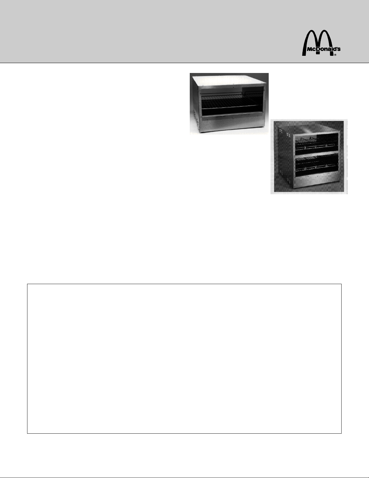
MODEL NO. STB-11
MODEL NO. STB-22
LIMITED WARRANTY
This product is warranted to be free from defects in material and/or workmanship for a period of (2)
years from date of original installation not to exceed 30 months from date of shipment from our factory.
Printed circuit boards and platen are warranted for a period of (3) years from date of original installation
not to exceed 42 months from date of shipment from our factory. Any part or component which proves
to be faulty in material and/or workmanship within the warranty period will be replaced or repaired
without cost to the customer for parts or labor. (At the option of Prince Castle, Inc.)
This warranty is subject to the following exceptions/conditions:
z This warranty covers on location service (i.e., trip charges and or mileage). Travel mileage is
limited to 100 miles (200 kilometers) round trip (one trip per warranty) from an authorized Service
Agency or it's sub-service agency. All labor must be performed during regular working hours. Overtime premium will not be covered.
z Any use of non-genuine Prince Castle replacement spare parts voids this warranty.
z Damage caused by carelessness, neglect, and/or abuse (e.g., using wrong current, dropping , tam-
pering with or altering electrical components, or improper cleaning) is not covered.
z Equipment damaged in shipment, by fire, flood or an act of God.
This manual is for the exclusive use of licensees and employees of McDonald's Systems, Inc.
©1998 McDonald's Corporation
All Rights Reserved
Printed March
Part No. 536-507
EM 41
The United States of America
Printed in
Page 2
INTRODUCTION
The Heated Landing Shelfs are designed for special venues where space is at a premium.The STB-11 holds up
to 16 sandwiches on one shelf.The STB-22 holds up to 32 sandwiches on two shelves.
Adjustable lane dividers can be realigned for existing or new products. The Shelfs have adjustable heaters to
maintain correct temperatures at various locations. Plastic Trays are used for Regular Hamburgers and Regular
Cheeseburgers only.
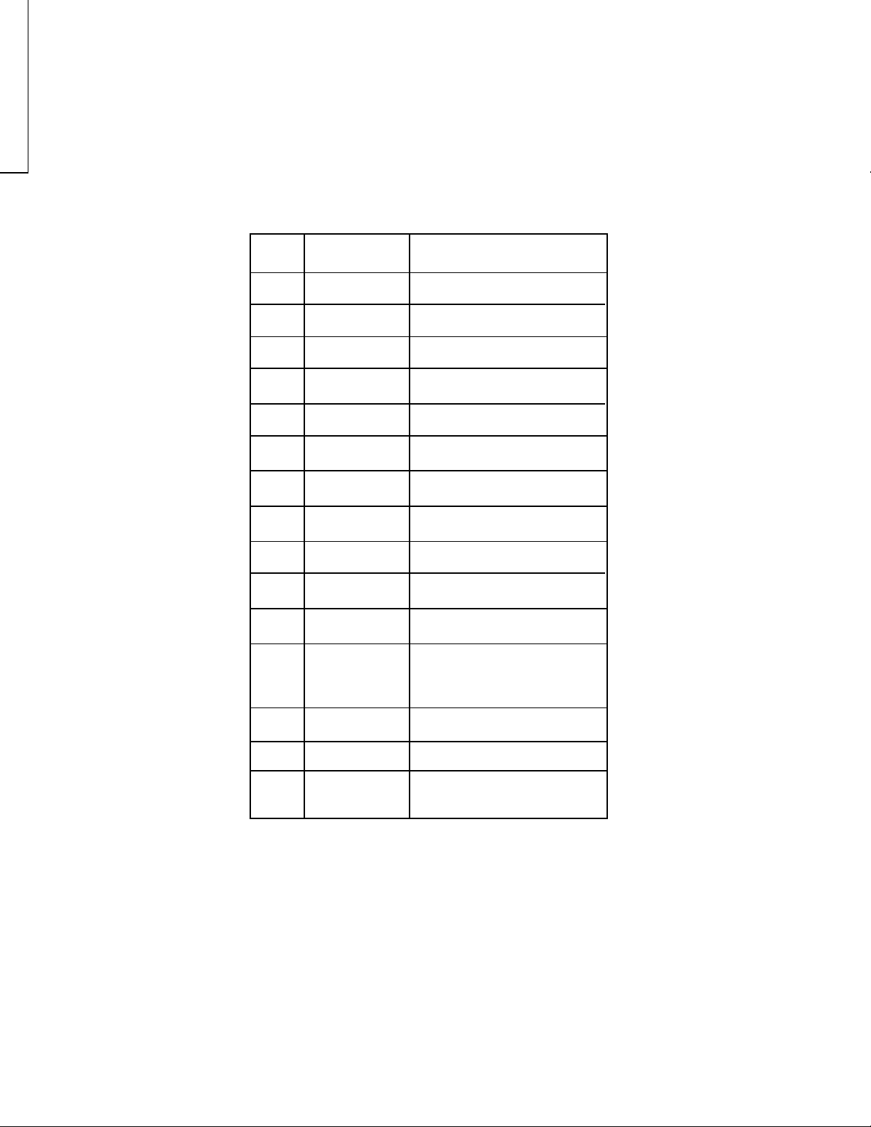
PARTS IDENTIFICATION LIST
ITEM PART NO. DESCRIPTION
2
3
4
5
6
7
8
9
10
11
12
13
536-23
536-17
65-037S
76-640
73-015
536-33
536-9S
411-133s
89-156
213-257S
78-166S
72-207S
72-200-11
72-234S
Lane Divider
Wire Rack
Solid State Relay
Slotted Binder Head Screw
Hex Nut
Potentiometer Door
P.C. Board Assy
Potentiometer Assy.
Spacer
Pilot Light
Rocker Switch
Power Cord (STB-22)
Power Cord (STB-11)
Power Cord (CE)
14
15 z
536-31
536-45S
z NOT
SHOWN
Control Panel Assy.
Heater
2
Page 3
Set - up
EQUIPMENT SET-UP AND
CLOSE PROCEDURES
ORDERING / SERVICE INFORMATION
PARTS
1. Place Heated Landing Shelf on counter.
2. Insert the 6 FT Power Cord W/ NEMA 15-P Plug into
a 120 Volt, grounded outlet. NOTE: International
units come with a 6 FT Power Cord with no Plug
attached. International units should be attached to a
220 Volt, 50/60 Hertz, Single Phase Outlet.
NOTE: This should be a dedicated outlet. No other
equipment should be operating on this line (i.e.
fryers, refrigerators, cash registers, etc.)
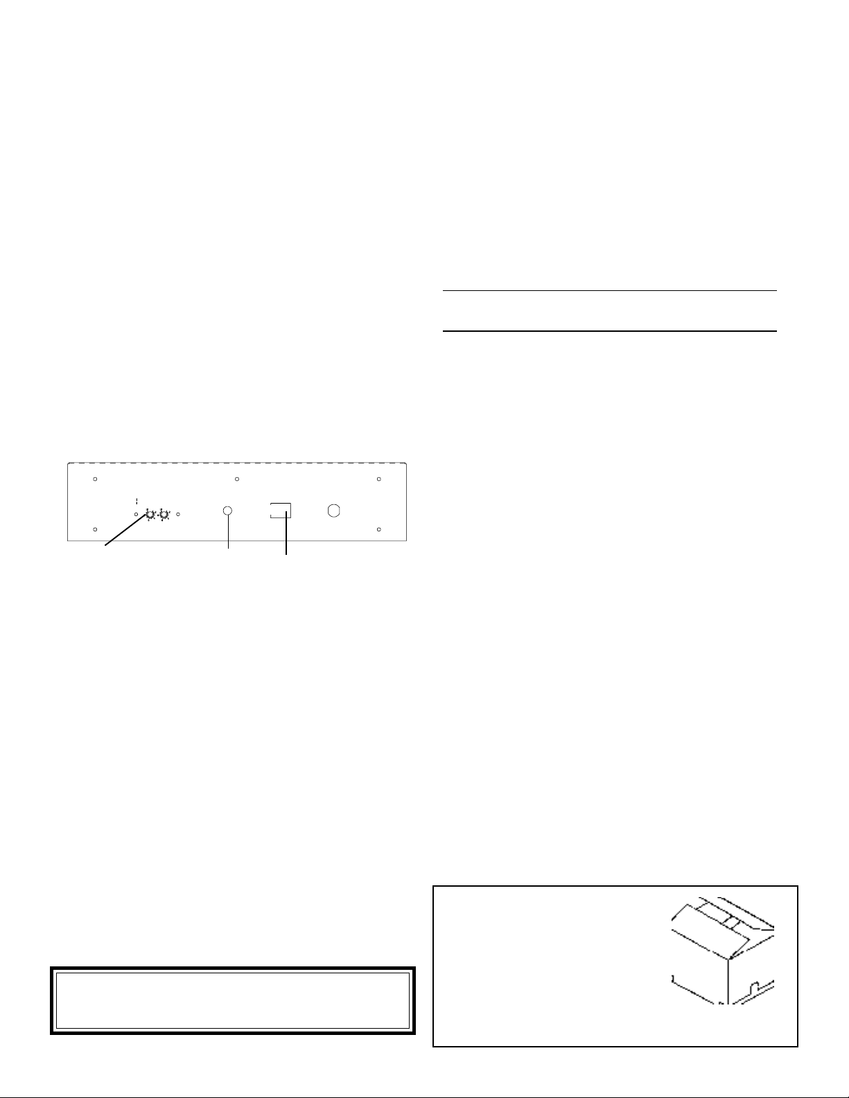
3. Turn Power Switch (A) "ON". The Amber Power
Light (B) will turn on. Allow 20 minutes for warm-up.
FRONT CONTROL PANEL
CAUTION - HOT CAUTION - HOT
LOWER
UPPER
HEATER
HEATER
NOTE: STB-11 has
POWER
ON
B
OFF
ON
A
(1) Adjustment Potentiometer
1. WHERE AND HOW TO ORDER REPLACEMENT
PARTS.
To order replacement parts. Look on the back of
the price list for your local Prince Castle Service
Center, or call Prince Castle at 1-800-323-2930
and we will help you.
Then call your local Prince Castle Service Center.
Fill in name and number here.
INTERNATIONAL
Contact your kitchen Equipment Supplier or designated
repair facility for parts and service.
2. PARTS RETURNS
Should the need ever arise to return parts to your
Center for credit, it is necessary that you:
Obtain authorization from your Service Center
for such return;
All warranty situations should be handled by your
Service Center.
3. PRICES
4. Snap in Wire Racks with lip to counter.
5. Place all other products on the wire rack.
6. Refer to your operation and procedure manual for
correct holding times.
Close Procedures
Caution: Before unplugging power cord make sure
Power Switch is in "OFF" position.
1. Unplug Heated Landing Shelf From outlet.
2. Allow unit to cool down.(About 15 Minutes)
3. Wipe down with a damp cloth.
.
CAUTION: When cleaning do not pour water on
the heaters. This may cause an electrical hazard
and damage to the sensitive solid state circuitry.
A. All prices are F.O.B. Prince Castle Service
Center or F.O.B. factory, Carol Stream Illinois.
B. All prices are subject to change without notice.
These prices are exclusive of all sales taxes or any
special taxes which may be levied by federal, state,
or city governments.
Parts price lists are sent to the U.S.A. restaurants
once a year, which indicates the prices available
from your local Center.
4. TERMS
Net 30 days.
INSPECT
CARTON
Remove product from carton...
if damaged:
Notify Carrier
Save caton and packing material
Contact Prince Castle Customer Sales for replace-
ment.
4
Page 4

EXPLODED VIEW
NOTE: The one and two shelf Transfer Bins have the same internal parts.
3
Page 5

TROUBLESHOOTING GUIDE
In the event that the shelve(s) do not heat, first determine that power has not been interrupted to the Heated
Landing Shelf . This can easily be confirmed by the "POWER ON" light on the control panel. Assuming that the
unit has power, determine whether or not the temperature adjustments are at their proper settings.
To fully diagnose the Heated Landing Shelf further, it will be necessary to access the control compartment. To
accomplish this, first unplug the power cord, remove the four (4) corner screws and the top center screw on the
cover, and slide the drawer out. The cover must be lifted over the lip of the chassis before the drawer can be
pulled out. Replug the power cord. Turn the Heated Landing Shelf on.
CAUTION: HAZARDOUS VOLTAGE PRESENT WITHIN CONTROL COMPARTMENT. Do not touch any
connector or Printed Circuit Board while the Heated Landing Shelf is plugged in.
Note the four red LEDS on the printed circuit board under the letters "UPR" (meaning upper) and "LWR" (meaning
lower). The upper two LEDs indicate that the circuitry is telling the Heater Control Relays to turn on ("RLY SIG").
The lower LEDs indicate that the Heater Control Relays are on ("RLY ON").
PROBLEM CAUSE
"RLY SIG" LED does not turn on,
even when temperature setting is
increased.
"RLY SIG" LED is on, but "RLY ON"
LED is off.
"RLY SIG" and "RLY ON" LEDs are
both on but no heat.
Too much heat. "RLY SIG" and
"RLY ON" LEDs stay on even when
temperature setting is decreased.
Temperature Adjust disconnected
1.
from circuit board.
Inoperable Circuit Board.
2.
InoperableTemperature Adjust Con-
3.
trol.
Temperature Sensor Wire Discon-
4.
nected at Circuit Board.
Temperature Sensor Wire Discon-
5.
nected within cabinet.
"RLY CONTROL" connector loose.
1.
"RLY DIAGN" connector loose.
2.
Loose connection on Heater
3.
Control Relay.
Inoperable Heater Control Relay.
4.
Loose connection in heater
1.
harness within cabinet.
Inoperable Heater.
2.
Inoperable Temperature Adjust
1.
Control.
Inoperable Circuit Board.
2.
SOLUTION
1.
Reconnect Temperature Adjust to
Circuit Board.
2.
Replace Circuit Board.
3.
Replace Temperature Adjust Control.
4.
Check Sensor Wire Connection on
Circuit Board.
5.
Check Sensor Wire Connection inside Cabinet.
1.
Check Connector for tightness.
2.
Check Connecter for tightness.
3.
Check Connection To Relay.
4.
Replace Heater Control Relay.
1.
Check all Heater Harness Connections.
2.
Replace Heater.
1.
Replace Temperature Adjust Control.
2.
Replace Circuit Board.
Too much heat. "RLY SIG" LED is
off but "RLY ON led is on.
Heated Landing Shelf is heating
okay, but no "POWER ON" light.
No heat. "POWER ON" light, "RLY
SIG", and "RLY ON" LEDs are off.
Heated Landing Shelf is plugged in
and turned on.
Inoperable Heater.
3.
Inoperable Heater Control Relay.
1.
"PWR LIGHT" connector loose.
1.
Inoperable "POWER ON" light.
2.
Tripped circuit breaker in store.
1.
"PWR SWITCH" connector loose.
2.
Connections at Power Switch loose.
3.
Inoperable Circuit Board.
4.
Inoperable Power Switch.
5.
6.
Inoperable Power Cord.
5
3.
Replace Heater.
1.
Replace Heater Control Relay.
1.
Check "PWR LIGHT" Connection.
2.
Replace "POWER ON' light.
1.
Check Circuit Breaker in store.
2.
Check "PWR SWITCH" Connection.
3.
Check Power Switch Connection.
4.
Replace Circuit Board.
5.
Replace Power Switch.
6.
Replace Power Cord.
Page 6

CARD NO.
HEATED LANDING SHELF
Planned Maintenance System
Maintenance Requirement Card (MRC)
Temperature & Calibration of STB-22& STB-11
The Heated Landing Shelf leaves the factory with the plate temperature set at 225-230 F. ( 107-110
C.)Readings with the Surface Probe should be taken at the surface of the heaters 2" to the right of the
center screw on top and bottom (SEE FIGURE BELOW). NOTE: Because the location of the Heated
Landing Shelf may vary from restaurant to restaurant there may be a need to adjust the
temperature setting due to climate control conditions in that location.
○○○
HEATER
SURFACE
2"
○○○
CENTER
SCREW
oo
72
The following "Water Test" is intended for use only when the integrity of the Heated Landing Shelf is
questioned by regulatory agencies, ie; health department, etc.
MATERIALS REQUIRED:
1ea. 8oz. paper(CAUTION: Do not use "Waxed Paper Cup) or styrofoam coffee cup with lid (lid may
be plastic)
1ea. "K" type thermometer and probe, or a conventional bulb type thermometer capable of reading in the
100-200 F. range (35-100 C.)
PRODUCT SIMULATION:
Place 4 tablespoons (1/4 cup) of water in the paper cup. Use hot water, or microwave until the temperature
of the water measures 155-160 F. (68 - 71 C.)Immediately place the lid on the cup and place the cup
anywhere on the wire rack in the Transfer Bin.
WARNING: DO NOT place any object under the cup (paper, plastic, foil, cardboard, etc...) to help
"balance the cup" on the rack.
After 10 minutes, place the cup on the counter, immediately insert thermometer end (or needle probe) thru
a small (1/4" max.) hole in the lid, and record the temperature of the water. If the temperature is between
140-150 F (60 - 65 C.) the unit is operating as intended. If the temperature of the bin is too high or too
low it can be adjusted by turning the adjustment potentiometer located behind the access door on the front
of the transfer bin.
NOTE: To raise access door loosen the screw in between the two heater pots,(NOTE: on STB-11
screw above single Pot) then raise up exposing the adjustment potentiometer(s) .
o
o
o
o
o
o
Turning the pot clockwise will adjust the temperature up, turning it counter clockwise will adjust it down.
Each small mark will cause about a 5 Degree adjustment in temperature.
Page 7

WIRING DIAGRAM
6
Page 8

WIRING DIAGRAM
(STB-11)
6
Page 9

WIRING DIAGRAM
(STB-22)
7
 Loading...