

Page 1
Operation
Product Identification
TOP
COVER
POWER
SWITCH
CONTROL
PANEL
DOOR
HANDLE
Electrical Specifications
120 VAC, 60 Hz, 580W, 1-Phase
220 VAC, 50 Hz, 580W, 1-Phase
The 120 VAC version will have the UL mark on the label
and the 220 VAC version will have the CE mark.
355 East Kehoe Blvd. • Carol Stream, IL 60188 USA
Telephone: 630-462-8800 • Toll F ree: 1-800-PCASTLE
Fax: 630-462-1460 • www.princecastle.com
LIMITED WARRANTY
This product is warranted to be free from defects in material and/or
workmanship for a period of two (2) years from date of original
installation, not to exceed 30 months from date of shipment from
our factory. Any part or component which proves to be faulty in
material and/or workmanship within the warranty period will be
replaced or repaired (at the option of Prince Castle, Inc.) without
cost to the customer for parts or labor.
This warranty is subject to the following exceptions/conditions:
• Use of any non-genuine Prince Castle parts voids this
warranty and all work must be performed by an authorized
Prince Castle Service Agent.
• All labor shall be performed during regular work hours.
Overtime premium will not be covered.
• Travel charges are limited to 100 miles/200 km round trip, 2
hours travel time, one trip per repair.
• Damage caused by carelessness, neglect, and/or abuse (e.g.,
using wrong current, dropping, tampering with or altering
electrical components, or improper cleaning) is not covered.
• Equipment damaged in shipment, by fire, flood or an act of
God is not covered.
• Damage to non-stick coated surfaces is not covered by this
warranty.
TABLE OF CONTENTS
Product Ide n ti fic a ti o n . . . . . . . . . . . . . . . . . . . . . . . . . . . . . . . 1
Electrical Specifications . . . . . . . . . . . . . . . . . . . . . . . . . . . . . 1
Warranty. . . . . . . . . . . . . . . . . . . . . . . . . . . . . . . . . . . . . . . . . 1
Safety Information . . . . . . . . . . . . . . . . . . . . . . . . . . . . . . . . . 2
Introduction . . . . . . . . . . . . . . . . . . . . . . . . . . . . . . . . . . . . . . 2
Model Number . . . . . . . . . . . . . . . . . . . . . . . . . . . . . . . . . . . . 2
Installation . . . . . . . . . . . . . . . . . . . . . . . . . . . . . . . . . . . . . . . 2
Operation . . . . . . . . . . . . . . . . . . . . . . . . . . . . . . . . . . . . . . . 3
Troubleshooting . . . . . . . . . . . . . . . . . . . . . . . . . . . . . . . . . . . 4
Exploded Views and Parts Lists . . . . . . . . . . . . . . . . . . . . . . 5
Wiring Diagram . . . . . . . . . . . . . . . . . . . . . . . . . . . . . . . . . . . 6
Pie Merchandiser
Manual
524-Series
524-500revD-EN Printed in USA 12/09 © 2009
Page 2
Pie Merchandiser
Safety Information
Knowledge of proper installation, operation and maintenance
procedures is essential to ensure safe operation of any
equipment.
• Always have dry hands prior to turning the ON/OFF switch
ON or OFF.
• Turn OFF the ON/OFF switch any time the cabinet is not in
use.
• If an electrical shock is felt when touching the cabinet,
disconnect the power immediately and call Prince Castle
Technical Service Department for assistance and service.
• If you find the power cord is frayed or the plug damaged,
DO NOT PLUG IT INTO THE ELECTRICAL
RECEPTACLE. IF IT IS ALREADY PLUGGED IN, SHUT
OFF THE MAIN CIRCUIT BREAKER, LOCATED IN THE
BREAKER BOX AT THE REAR OF THE STORE. TH EN
DISCONNECT THE PLUG.
• DISCONNECT THE POWER CORD BEFORE
A TTEMPTING ANY REP AIRS TO THE CABINET AND/OR
CLEANING THE UNIT.
• DO NOT SUBMERGE THE CABINET. ELE CTR I C A L
COMPONENTS AND WIRING PRESENT A HIGH
SHOCK HAZARD WHEN WET.
Introduction
The 524-MCDC/-MCDCCE Pie Merchandiser is designed to
hold pies at proper serving temperatures. The cabinet has a
programmable temperature controller with a low temperature
alarm. The controller is factory pre-set for baked pies with a
holding temperature of 165°F (74°C). The controller’s
temperature setting needs to be adjusted for fried pies which
require a holding temperature of 155°F (69°C).
The heater can be accessed for service by removing the top
cover. There is also a bottom panel to access the wiring and the
switch.
The cabinet is designed to hold 42 baked pies or 36 fried pies.
Each cabinet includes a removable pie caddy.
Model Number
Model Description Model Description
524-MCDCCE 220-240 VA C, Schuko plug 524-MCDCP 220-240 VA C, 16A pin & sleeve plug
524-MCDCGB 220-240 VAC, BS1363 plug 524-MCDC 120 VA C, NEMA 5-15 plug
524-MCDCF 220-240 VAC, no plug
Installation
Remove the cabinet from shipping carton making sure
all packing materials are removed from the carton and
cabinet.
1
Check to ensure all components are included:
Cabinet, Pie Caddy, Equipment Manual.
2
Read this equipment manual completely before
operating the cabinet.
3
Locate the cabinet on clean, dry surface.
4
Level the cabinet by turning the adjustable feet on the
bottom of the unit. This prevents the cabinet from
tipping over and makes the boxed product easier to
remove.
5
Clean cabinet thoroughly before use. See PM Card.
6
Connect the cabinet power cord to a correctly-wired
and protected power source.
7
524-Series
Printed in USA 12/09 © 2009 2 524-500revD-EN
Page 3
Pie Merchandiser
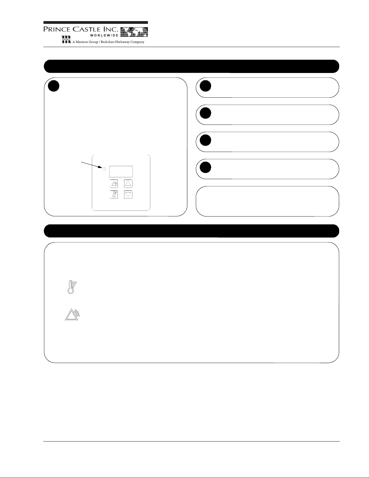
Operation
The power switch is located at the base of the cabinet,
below the door. T urn the power switch ON. Preheat
cabinet for 30 minutes. When the cabinet is turned on,
the air heater will operate until the cabinet reaches the
air temperature setpoint. The display will read the
actual cabinet temperature. The heat “ON” light will
illuminate when the cabinet air temperature is 1°F or
more below the air temperature setpoint. It will turn off
when the cabinet temperature reaches the air
temperature setpoint. The controller display will flash
alternately LO and the actual cabinet air temperature
until it reaches the low temperature alarm setpoint.
1
Controller
Heat “ON”
Indicator
After preheating, load boxed pies into cabinet.
2
Cabinet dispenses pies from the bottom, underneath
the door.
3
When cabinet is not in use, turn power off.
4
This cabinet must be cleaned WEEKLY. See PM Card.
5
NOTE: The pie caddy has a reserve storage of 12 pies.
This reserve is intended to provide additional pies while a
new batch of pies is being baked. Holes beneath the door
provide visual indication of low pie level in the cabinet.
Programming Instructions
To View or Change the Temperature setpoint:
Turn the power on. To view the temperature setpoint, press and hold the temperature set button. To change the
temperature setpoint, press and hold the temperature set button, press the up or down arrow button until the desired
air temperature is displayed. The display will advance in 1° increments.
To View or Change the Alarm setpoint:
Turn the power on. To view the alarm setpoint, press and hold the alarm-reset button. To change the alarm setpoint,
press and hold the alarm-reset button, and press the up or down arrow button until the desired alarm temperature is
displayed. The display will advance in 1° increments.
To View or Change Temperature Scale:
The cabinet is programmable for a temperature scale in degrees Fahrenheit and Centigrade (Celsius). Turn power
off. Hold down both up and down arrow buttons. Turn power back on while holding both arrows. Display will show
current scale (C or F). If desired, push the up or down arrow to change the scale. Turn power off to save change.
The controller has been factory pre-set for baked pies with a holding temperature of 165°F (74°C). The controller’s temperature
setting needs to be adjusted for fried pies which require a holding temperature of 155°F (69°C). To ensure food safety, a low
temperature alarm will sound when the cabinet temperature falls below 140°F (60°C). NOTE: To clear the LOW TEMPERATURE
ALARM, press the button with the picture of a thermometer.
524-Series
524-500revD-EN 3 Printed in USA 12/09 © 2009
Page 4

Pie Merchandiser
Non-Scheduled Maintenance
Equipment surfaces may be hot. It is recommended that the unit be turned off for at least 10 minutes prior to performing any maintenance procedure.
Changing Illuminated Front Graphic on Door:
Tools: Phillips Screwdriver
Remove the four screws on the sides of the door and remove the door trim. Slide the POP graphic out. Slide new POP graphic
in, making sure to leave white diffuser background panel in place. Replace the door trim and secure with screws.
Changing the Light Bulb in the Door:
Tools: Phillips Screwdriver
The POP graphic on the front door is illuminated by one fluorescent bulb. If the bulb burns out, turn off the cabinet. Remove the
four screws (save removed screws) on the sides of the door trim and remove the trim along with the POP graphic and white
diffuser. Replace the burned out bulb, the white diffuser, POP graphic and door trim. Secure the door trim with the previously
removed screws. Turn the power switch on.
WARNING
Troubleshooting
524-Series
SYMPTOM DISPLAY READS POSSIBL E CAUSE REMEDY
No power Blank Facility circuit breaker tripped Reset circuit breaker
Power cord to unit is unplugged Plug in power cord
Faulty transfor mer Replace
Faulty controller Replace
Faulty ON/OFF switch Replace
Faulty wiring Follow wiring per diagram
No Heat/Low Temp Ambient air temperature Hi limit faulty or tripped Reset/Replace
Faulty heat element Replace
Faulty relay Replace
Faulty air probe Replace
Faulty controller Replace
Door not closed Make sure Merchandiser door is closed
Controller LEDs LED segments are out/dim Loose wiring Follow wiring per diagram
Faulty controller Replace
Product not getting
hot enough
Function key does
not operate
Normal Wrong setting or menu being used Correct temperature setting
Normal Faulty controller Replace
properly
Check calibration with MRC Card
Printed in USA 12/09 © 2009 4 524-500revD-EN
Page 5

Pie Merchandiser
Exploded View and Parts List
* Not shown
No. Part No. Description
1 524-002S Heating Element
1 524-002CES Heating Element (MCDCCE)
2 524-003S Motor w/ Fan
2 524-003CES Motor w/ Fan (MCDCCE)
3 524-004S Cabinet Fan
3 524-004CES Cabinet Fan (MCDCCE)
4 524-005S Controller/Display PCB
5 524-006S Light Socket
6 524-007S Light Bulb
7 78-228S Power Switch
9 72-200-15S Power Cord*
10 524-008S Pie Caddy
No. Part No. Description
11 524-009S Power PCB
11 524-009CES Power PCB (MCDCCE)
12 65-058S Rela y
13 524-010S Ballast
13 524-010CES Ballast (MCDCCE)
14 524-011S Temperature Probe*
15 524-012S Graphic w/ Backer Plate
16 524-013S Feet (4)
17 524-015S Hi-Limit Switch*
17 524-015CES Hi-Limit Switch (MCDCCE)*
18 524-016S PC Display Overlay*
(4 per unit)
524-Series
524-500revD-EN 5 Printed in USA 12/09 © 2009
Page 6

Pie Merchandiser
Wiring Diagram
524-Series
ASSY PROBE
POWER CORD
HEATER
DISPLAY PCB
TO GROUND
BRN
TEMPERATURE
WHITE
LIMIT
BLACK
BLACKRED
WHITE
BLACK
POWER SWITCH
BLU
BRN
TERMINAL BLOCK
BLU
BRN
HUBBLE
120 VAC
BRN
BLU
GRN/YEL
BRN
RELAY
MOTOR
BLACK
BLU
BRN
BLACK
FAN
BLU
BRN
TRANSFORMER PCB
WHITE
GRN/YEL
WHITE
BLACK
BLACK
LAMP
BALLAST
GRN/YEL
TO GROUND
120 V
Printed in USA 12/09 © 2009 6 524-500revD-EN
Page 7

Pie Merchandiser
Wiring Diagram
BLACK
BLACK
BLACKRED
TO GROUND
BLU
GRN/YEL
BRN
BRN
WHITE
BLACK
BLU
BRN
GRN/YEL
GRN/YEL
TO GROUND
WHITE
WHITE
BLACK
BLACK
BLU
BRN
WHITE
BLACK
BRN
BRN
BLU
BRN
BLU
TERMINAL BLOCK
POWER SWITCH
TEMPERATURE
LIMIT
HUBBLE
FILTER
230 VAC
POWER CORD
DISPLAY PCB
RELAY
TRANSFORMER PCB
BALLAST
LAMP
FAN
ASSY PROBE
MOTOR
230 V
HEATER
524-Series
524-500revD-EN 7 Printed in USA 12/09 © 2009
Page 8

PREP EQUIPMENT
Prince Castle
Pie Merchandiser
Model 524
Daily maintenance tasks
PR 63 W1 Clean merchandiser
Model 524
REMOVABLE
PIES
PR 63
Prince Castle Pie Merchandiser Model 524 PR 63
CONTROL
PANEL
DOOR
HANDLE
POWER
SWITCH
Hazards
These icons alert you to a possible risk of personal injury.
Equipment alerts
Look for this icon to find information about how to avoid damaging the
equipment while doing a procedure.
Tips
Look for this icon to find helpful tips about how to do a procedure.
©McDonald’s Corporation · Planned Maintenance Manual · Revised November 2008
Page 9

Clean Pie Merchandiser Weekly PR 63 W1
Why
Time required
Time of day
Hazard icons
Tools and supplies
To keep the merchandiser clean and food safe
10 minutes to prepare 15 minutes to complete
At close For 24-hour restaurants: during late-night shift
Chemicals Electricity Hot Surfaces
SolidSense All Purpose
Super Concentrate (APSC)
Procedure
Turn off and unplug the pie
1
merchandiser. Remove all
food products from the
cabinet. Let the merchandiser
cool with the door open for at
least 10 minutes.
SolidSense sanitizer
Bucket, clean,
sanitizer soaked towels
Bucket, soiled towels KAY®
Clean the cabinet interior and
3
exterior surfaces by spraying a
clean, sanitizer soaked towel
with EXCEED and wiping. Use
®
a KAY
NO-SCRATCH™ pad
on heavy soils.
NO-SCRATCH™ Pad
EXCEED Glass &
Multisurface Cleaner
Prince Castle Pie Merchandiser Models 524
Electricity
Unplug the merchandiser
before cleaning.
Hot Surfaces
Do not attempt to clean a hot
merchandiser.
Remove the pie caddy from the
2
cabinet. Bring the pie caddy to
the back sink. Wash in back
sink, rinse, and sanitize. Use a
®
KAY
NO-SCRATCH™ pad
on heavy soils if needed.
Chemicals
Sanitizer solution
Equipment Alert
Cleansers, detergents, degreasers, sanitizers, or
bleaching agents that contain
chlorides or phosphates will
cause permanent damage to
stainless steel products. The
damage appears as pits,
cracks, and surface discoloration. This damage is
permanent and is NOT cov-
ered by the warranty.
Chemicals
Sanitizer solution
Equipment Alert
DO NOT SPRAY WITH
WATER DURING
CLEANING.
The heater components should
not be exposed to direct contact with water or cleaning
sprays.
Thoroughly air-dry the cabinet
4
and pie caddy. Place the caddy
back in the cabinet.
Weekly PR 63 W1
Reconnect the power cord.
5
©McDonald’s Corporation · Planned Maintenance Manual · Revised November 2008 Page 1 of 1
 Loading...