

Page 1
Heated Landing Shelf
Prince Castle Model No. STB-36BF, & 48BF Series
This equipment chapter is to be placed in the
Miscellaneous Section of your Equipment Manual
MANUFACTURED BY
PRINCE CASTLE INC.
355 EAST KEHOE BLVD
CAROL STREAM, IL 60188 USA
PHONE 1-630-462-8800
TOLL FREE NUMBER
1-800-323-2930
FAX: 1-630-462-1460
WARRANTY .........................................................................................................................................................Page 1
INTRODUCTION..................................................................................................................................................Page 2
PARTS IDENTIFICATION ................................................................................................................................... Page 2-6
EXPLODED VIEW ................................................................................................................................................ Page 2-6
EQUIPMENT SET-UP AND CLOSE PROCEDURES......................................................................................Page 7
ORDERING PARTS.............................................................................................................................................Page 8
TROUBLESHOOTING GUIDE ...........................................................................................................................Page 9
WIRING INFORMATION..................................................................................................................................... Pag e 11
LIMITED WARRANTY
This Product is warranted to be free from defects in material and/or workmanship for a period of two (2) years
from date of original installation not to exceed 30 months from date of shipment from our factory. Any part or
component (with the exception of light bulbs) which proves to be faulty in material and or workmanship
within the warranty period will be replaced or repaired without cost to the customer for parts or labor. (At the
option of Prince Castle, Inc.)This warranty covers on-location service (i.e.,trip charges and or mileage). Travel
mileage is limited to 100 miles (200 Kilometers) round trip(one trip per warranty) from an authorized service
agency or its sub-service agency.
This warranty is subject to the following exceptions/conditions:
1. Any use of Non-Genuine Prince Castle Spare Parts voids this warranty.
2. All labor shall be performed during regular working hours. Overtime premium will not be covered
3. Damage caused by carelessness, neglect, and/or abuse (e.g., using wrong current, dropping, tampering
with or altering electrical components, or improper cleaning) is not covered. Equipment damaged in
shipment, by fire, flood or an act of God.
This Manual is for the Exclusive use of Licensees and Employees of McDonald's Systems, Inc.
2001McDonald's Corporation
All Rights Reserved
Printed In November 1996
EM 44
Misc 44
Part No. 536-527
Printed in the
United States of America
Page 2
INTRODUCTION
The Heated Landing Shelf comes with adjustable lane
dividers that can be realigned for existing or new products. The Heated Landing Shelf holds up to a 72 sandwich capacity with 12 product lanes for Model No.
STB-36, or up to a 96 sandwich capacity with 16
product lanes for Model No. STB-48. Adjustable upper
and lower heaters maintain correct temperatures at
various locations.
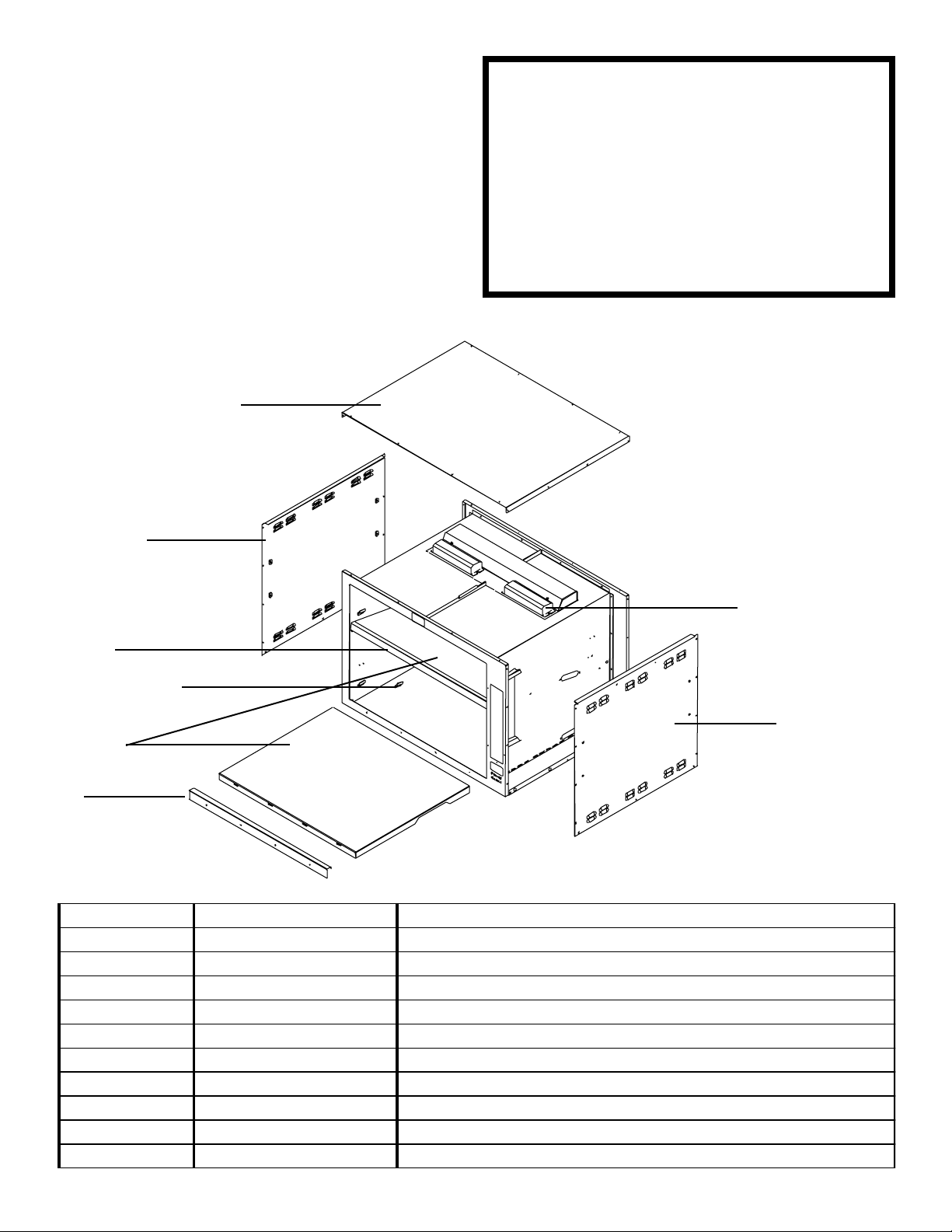
STB-36BF EXPLODED VIEW
5
This unit utilizes Radiant Energy to maintain
food temperature. The Racks, Sides, Top, and
Internal Air Temperature of the unit will remain
relatively cool while in operation. The only parts
of the unit with a Hot Surface are the Black
Decks which contain the Radiant Heat Source.
Please refer to this Operating Manual for Calibration. Check the Actual Food Temperature or
Surface Temperature of the Black Decks with
an appropriate thermometer. Measuring the Air
Temperature IS NOT an indication of the Food
Temperature.
4
3
2
7
1
Item Part # Description
1 536-104 Lower Face
2 536-199S Bracket w/Screws (pkg of 4)
3 536-420 Upper Face
4 536-139 Side Panel
5 536-120 Top Cover
6 536-601S Ballast (240 Volt)
7 536-127S Heater Assy
* 536-443 Lamp Guard (Not Shown)
* 72-200-16 Line Cord (Not Shown)
* 88-633-3S Florescent Lamp (Not Shown)
6
4
2
Page 3
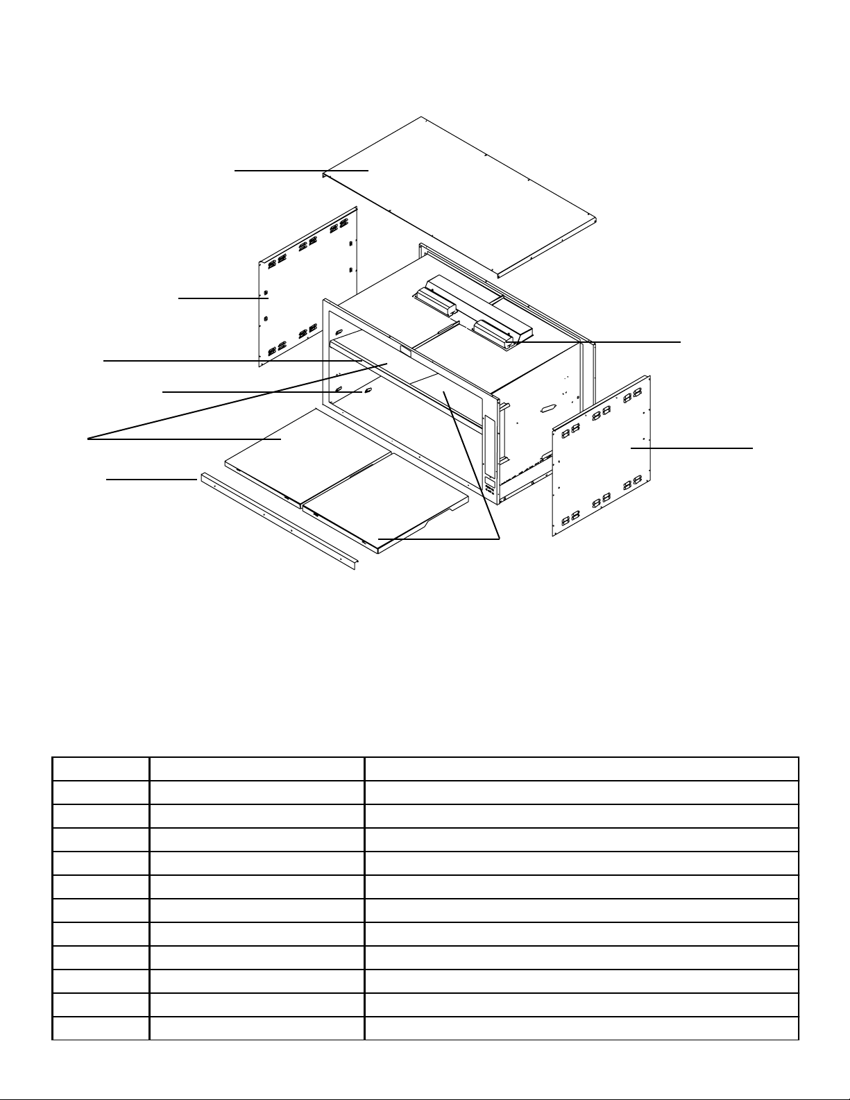
STB-48BF EXPLODED VIEW
5
4
6
3
2
7
1
8
3
Item Part # Description
1 536-150 Lower Face
2 536-199S Bracket w/Screws (pkg of 4)
3 536-414 Upper Face
4 536-139 Side Panel
5 536-148 Top Cover
6 536-601S Ballast (240 Volt)
7 536-172S Heater Assy. (Left Side)
8 536-255S Heater Assy (Right Side)
* 536-443 Lamp Guard (Not Shown)
* 72-200-16S Line Cord (Not Shown)
* 88-633-3S Florescent Lamp (Not Shown)
4
4
Page 4
10
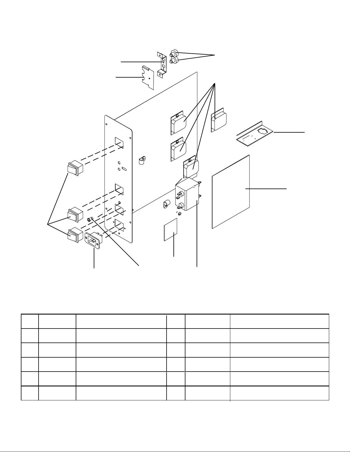
STB-36BF Control Box
9
11
8
7
6
1
3
2
ItemPart #
Description
1 78-184S Lighted Rocker Switch
2
3
4 65-037S
5 421-208S
536-348S
536-197S
Status Light
Control P.C. Board Assy.
Relay
P.C. Board Assy. 10 88-612
4
5
Item
Part #
6 536-317
7 536-33
8
411-133S
9
536-359
Description
Potentiometer Bracket
Potentiometer Door
Potentiometer
Connector Bracket
Line Filter
3
Page 5

STB-48BF Control Box
9
10
8
7
6
5
1
2
3
4
Item Part # Description Item Part Description
1 78-184S Lighted Rocker Switch 6 65-037S Relay
2 536-348S Status Light Assy. 7 411-133S Potentiometer
3 88-626 Filter 8 536-317 Potentiometer Bracket
4 536-241 Connector Bracket 9 536-33 Potentiometer Door
5 536-197S Control P.C.Board Assy. 10 421-208S P.C. Board
5
Page 6

STB-36BF & STB-48BF Heated Landing Shelf
Accessories
3
2
4
5
Item Part # Description
1 536-218 Lane Divider
2 536-213 Wire Rack (FHB-36)
536-214 Wire Rack (FHB-48)
3 536-131 Time Card Storage Rack (FHB-36)
536-167 Time Card Storage Rack (FHB-48)
4 536-391QS Time Card Kit
5 536-132 Time Card Return Rack
6 536-411 Left Side Tray Bracket
7 536-412 Right Side Tray Bracket
* 536-410 Center Tray Bracket (FHB-48 Only) (Not Shown)
8 536-421 Tray Rod (FHB-36)
536-413 Tray Rod (FHB-48)
6
1
* Individual replacement time cards are available in packages of three. Contact Prince
Castle or a local Prince Castle Service Agent.
6
Page 7

EQUIPMENT SET-UP AND
CLOSE PROCEDURES
1. Place Heated Landing Shelf on counter and seal it
completely with a food approved sealant.
2. Insert Power Cord into a proper voltage receptacle
NOTE: This should be a dedicated outlet. No other
equipment should be operating on this line (i.e. fryers,
refrigerators, cash registers, etc.)
3. Snap in Wire Racks with lip toward counter. The
Lower Rack can be set at an angle by setting the rear
(Kitchen Side) Part of the racks in the upper brackets
located on the sides of lower shelves. The upper rack
adjustment is located in the front (Counter Side).
4. Attach Air Baffles By Sliding the two hooks located
on the air baffle over the top (restaurant side) of the wire
rack. Note: The rack in the upper compartment should
be positioned at a downward angle by setting the restaurant side of the wire rack in the lower rack brackets
located on the sides of the bin. The lower compartment
rack may be positioned at either a horizontal or angled
position.
5. Lane Dividers can be easily lifted out and moved to
accommodate different size products.
7. Loosen the two Phillips Head screws (A) on both sides of
the bin. NOTE: The screws only need to be loosened 2-3
turns DO NOT REMOVE. (See Figure 1)
8. Place key hole slots (B) on the time card rack over the
loosened screws and tighten. (See Figure 1)
9. The Time Card Return Rack can be mounted on either side
of the Heated Landing Shelf.
10. Loosen two Phillips Head screws (A) one on top and one
on bottom so the rack sits at an angle on side of the bin.
NOTE: The screws only need to be loosened 2-3 turns DO
NOT REMOVE. (See Figure 2)
11. Place key hole slot s (B) on the time card return rack over
the loosened screws and tighten. (See Figure 2)
A
B
<
Tilt Down Toward Kitchen Side
6. The Time Card Storage Rack will be mounted on the top of
the landing shelf on the kitchen side.
B
O O O O
A
FIGURE 1
FIGURE 2
12. Turn on the Lighted Rocker Switch marked MAIN
POWER.
Upper Heating
Shelf
Lighted
Rocker
Switch
Temperature
Controls
Lower Heating
Shelf
Lighted
Rocker
Switch
Status
Light
7
Main
Power
Lighted
Rocker
Switch
Page 8

13. Turn on the lighted rocker switches marked UPPER
HEATER and LOWER HEATER. The lights and heaters
will come on for both shelves and the unit will begin to
heat up. Allow 30 minutes for warm-up.
NOTE: The UPPER And LOWER shelves can be
operated as two seperate areas. During slow
periods one shelf may be used while the other
shelf is switched off.
14. Refer to the operations and training manual for
correct holding times.
CLOSE PROCEDURES
This appliance is not of water tight construction. Do not clean with a Water Jet / Jet Spray.
Do not immerse appliance in water.
CAUTION: Before unplugging Power Cord make sure all
Power Switches are in the "OFF" position.
1. Unplug Heated Landing Shelf.
2. Allow unit to cool down. (Approximately 15 minutes)
INSPECT CARTON
Remove product from carton.
If damaged:
X Notify carrier within 24 hours.
X Save carton and packing material.
X Prince Castle can assist with freight claims and
arranging for a replacement unit if field repair is
impossible, or if you find a part or parts missing In the
USA Contact Prince Castle at 1-800-323-2930 outside the USA contact your KES or your Local Distributor.
PARTS
1. Always refer to the Parts List in this manual. You
will then have a part number for reference when
ordering.
3. Wipe down with a damp cloth.
Caution: When cleaning do not pour water on
the heaters. This may cause an electrical hazard and damage to the sensitive solid state
circuitry. Do not use Grill Cleaner
2. All replacement parts should be purchased from
your local Prince Castle Service Center (see enclosed list). Outside the U.S.A contact your local
Prince Castle Distributor.
3. RETURNS: All inoperable warranty parts must
be returned to the Service Center.
8
Page 9

STB-36BF & STB-48BF P.C. Board Diagnostics
UPR1
LWR1
UPR2
LWR2
Status Light Diagnostic Troubleshooting
The main purpose of the Status Light is to signal the
operator that the Heated Landing Shelf is functioning
properly.
n Under normal conditions the Status Light will be a
steady green.
n Under a condition of malfunction, the Status Light
will flash red. At this point switch off either heater, if the
Status Light turns back to a steady green when you
turn off a particular heater the malfunction is related to
the switched off heater.
Control
Panel
NOTE: Never turn off the Main Power Switch when
experiencing a flashing red this will reset the Status
Light. A reset Status Light takes 20 minutes to warm
back up.
n The Status Light should never be off, amber/
yellow, or a steady red. Should this be the case, then
the electronics driving the Status Light itself has malfunctioned.
NOTE: Once you have determined which heater
compartment has malfunctioned, locate the diagnostic LED's on the P.C.Board. Follow the
Diagnostic Troubleshooting on page 9 of this
manual.
STATUS LIGHT
Diagnostic
LEDS
9
Page 10

STB-36BF & STB-48BF P.C. Board Diagnostics
LED Signal Corrective Action
Heater sensor leads are reversed. Locate the
Blinking Red
corresponding sensor leads and verify that the yellow
and red sensor wires are connected in the correct
position (YEL or RED). Reverse the leads if incorrect.
Locate corresponding sensor wires and make sure
Steady Red
leads are securely in the terminal and that there are no
broken wires. If all leads are secure and not broken
replace the associated heater assembly.
If there is no heat at all being generated replace the
heater assembly. If the shelf is heating, check for
Blinking Orange
loose wires in the relay diagnostic header. If wire
connections are good, replace the relay.
CAUTION: HIGH VOLTAGE PRESENT
If heater does not turn on, check quick connect at the
Steady Orange
relay. If connection is good, replace the relay.
CAUTION: HIGH VOLTAGE PRESENT
Upper 1&2 LED's or
Lower 1&2 LED's
Blink Red & Orange
The heater switch is in the off position. There
is a bad connection on the heater switch.
The heater switch is defective.
IMPORTANT SPECIAL TROUBLESHOOTING PROCEDURES
FOR STB-48BF FOOD HOLDING BIN ONLY
If the FHB-48 fails to heat and the lights do not turn on, determine that the unit is receiving electrical power. Check
line cord connections, check that the FHB-48 Power Switches are in the "ON" position (they should be glowing
when in the "ON" position), and lastly check the store's circuit breakers. Follow the Troubleshooting procedures
below.
SOLUTIONCAUSEPROBLEM
1. Unit appears to be "DEAD"
and it has been determined that
power is reaching the unit.
2. Both Lights on a shelf are out
but the shelf is heating. (Associated Diagnostic LED's are cycling on (Green) and off).
1. Inoperable Line Cord.
2. Inoperable Main Power Switch.
3. Unit has overheated and High Limit
Switch has tripped.
1. Inoperable Light Bulbs.
2. Lamp Fuse has Opened.
1. Replace Line Cord.
2. Replace Switch.
3. Reset High Limit Switch. NOTE:
High Limit Is Located inside the
Control Box on the bottom of the
unit.
1. Replace Bulbs.
2. Ensure Lamp Circuit is not
shorted and replace appropriate
lamp fuse.
10
Page 11

CARD NO.
HEATED LANDING SHELF
72
Planned Maintenance System
Maintenance Requirement Card (MRC)
Temperature & Calibration of STB Series Heated Landing Shelf
The Heated Landing Shelf leaves the factory with the plate temperature set at 225°- 230°F (107°- 110°C) for
Models STB-22 & STB-11 and 235°- 240°F (113°- 116°C) for Models STB-36 & STB-48. Readings with the
Surface Probe should be taken at the surface of the heaters 2" to the right of the center circle marking on top and
bottom (See Figure Below). NOTE: Because the location of the Heated Landing Shelf may vary from
restaurant to restaurant there may be need to adjust the temperature setting due to climate control
conditions in that location.
○○○
Heater
Surface
2"
○○○
Center
Circle Marking
(View Facing Control
Panel)
The following "Water Test" is intended for use only when the integrity of the Heated Landing Shelf is questioned
by regulatory agencies, ie; health department, etc.
MATERIALS REQUIRED:
1 ea. 8 oz paper (CAUTION: Do not use Waxed Paper Cup) or styrofoam coffee cup with lid (lid may be plastic).
1 ea. "K" type thermometer and probe, or a conventional bulb type thermometer capable of reading in the
100°-200°F Range (35°-100°C).
PRODUCT SIMULATION:
Place 4 tablespoons (1/4 cup) (60cc) of water in the paper cup. Use hot water, or microwave until the temperature
of the water measures 155°-160°F (68°-71°C) Immediately place the lid on the cup and place the cup anywhere
on the wire rack in the Heated Landing Shelf.
WARNING: DO NOT place any object under the cup (paper, plastic, foil, cardboard, etc...) to help "balance the cup"
on the rack.
After 10 minutes, place the cup on the counter, immediately insert thermometer end (or needle probe) thru a small
(1/4" max) hole in the lid, and record the temperature of the water. If the temperature is between 140°-150°F
(60°-65° C) the unit is operating as intended. If the temperature of the Heated Landing Shelf is too high or too low
it can be adjusted by turning the adjustment potentiometer located behind the access door on the control panel.
NOTE: On STB-11& STB-22 To raise the access door, loosen the screw between the two heater pots, then
raise the door to expose the adjustment potentiometers.
On STB-36 & STB-48 Loosen the screw to the right of the temperature controls and slide it to the right
exposing the adjustment potentiometers.
Turning the pot clockwise will adjust the temperature up, turning it counter clockwise will adjust it down. Each small
mark will cause about a 5 degree adjustment in temperature.
Page 12

STB-36BF SERIES WIRING DIAGRAM
STB-48BF SERIES WIRING DIAGRAM
11
Page 13

WIRING DIAGRAM AND INSTALLATION
MODELS STB-36AFJ ONLY
TO HARD WIRE UNIT REMOVE THE UPPER COVER EXPOSING THE CONTROL DRAWER.
FOLLOW THE INSTRUCTIONS BELOW USING THE WIRING DIAGRAM ABOVE.
8
 Loading...