

Page 1
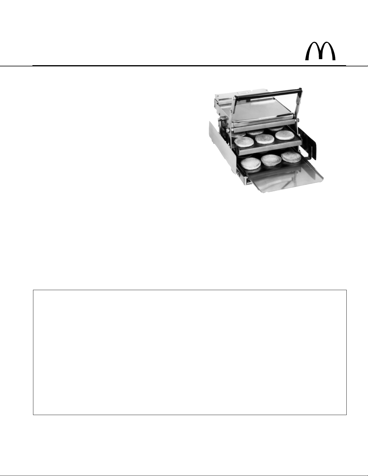
BIG MAC 6-BUN TOASTER
PRINCE CASTLE MODEL NO. 416-LFMCE
This equipment chapter is to be placed in the
toasters section of your Equipment Manual
MANUFACTURED FOR
MCDONALD’S
®
BY
PRINCE CASTLE INC.
355 KEHOE BLVD
CAROL STREAM, IL. 60188 USA
PHONE 1-630-462-8800
TOLL FREE NUMBER
1-800-323-2930
FAX:1-630-462-1460
WARRANTY ..................................................................................................................................................................................................... Page 1
INSTALLATION .............................................................................................................................................................................................. Page 2
OPERATION ..................................................................................................................................................................................................... Page 2
CLEANING ....................................................................................................................................................................................................... Page 2
MAINTENANCE ............................................................................................................................................................................................... Page 2
GENERAL INSTRUCTIONS ........................................................................................................................................................................... Page 3
ELECTRICAL REPAIRS ................................................................................................................................................................................. Page 3
CLOSING ......................................................................................................................................................................................................... Page 5
ORDERING/SERVICE INFORMATION ......................................................................................................................................................... Page 5
TROUBLESHOOTING ..................................................................................................................................................................................... Page 6
EXPLODED VIEW ............................................................................................................................................................................................ Page 7
PARTS IDENTIFICATION/FUNCTION ......................................................................................................................................................... Page 8
HARDWARE FOR MOUNTING PARTS ........................................................................................................................................................ Page 11
WIRING/ELECTRICAL INFORMATION....................................................................................................................................................... Page 12
WARRANTY
This product is warranted to be free from defects in material and/or workmanship for a period of (1) year from
date of original installation not to exceed 18 months from date of shipment from our factory. Any part or component which proves to be faulty in material and/or workmanship within the warranty period will be replaced or
repaired (At the option of Prince Castle, Inc.) without cost to the customer for parts or labor.
This warranty is subject to the following exceptions/conditions:
Any use of Non-genuine Prince Castle spare parts voids this warranty.
All labor should be performed during regular working hours. Overtime premium will not be covered.
The equipment is portable. Charges for on location service (e.g. trip charges, milage) are only
included in the provisions of this warranty for a failure which occurs within 30 days of installation.
Damage caused by carelessness, neglect, and/or abuse (e.g., using wrong current, dropping ,
tampering with or altering electrical components, or improper cleaning) is not covered.
Equipment damaged in shipment, by fire, flood or an act of God.
This Manual is for the Exclusive use of Licensees and Employees of McDonald’s Systems, Inc.
Printed in 1999
2000 McDonald’s Corparation Printed in the
All Rights Reserved United States of America
Part No. 416-590revA
Page 2
INSTALLATION
1. After you have removed the toaster from the carton,
inspect the unit for signs of damage. If there is
damage to the unit:
Notify carrier within 24 hours after delivery.
Save carton and packing materials for inspection
purposes.
Contact your local Prince Castle Supplier
2. Verify that all parts have been received.
3. Insert the power cord into a grounded 230 volt
outlet.
4. Ensure that the platens are in the up position while
the toaster warms up. This will make sure the
timer is not activated.
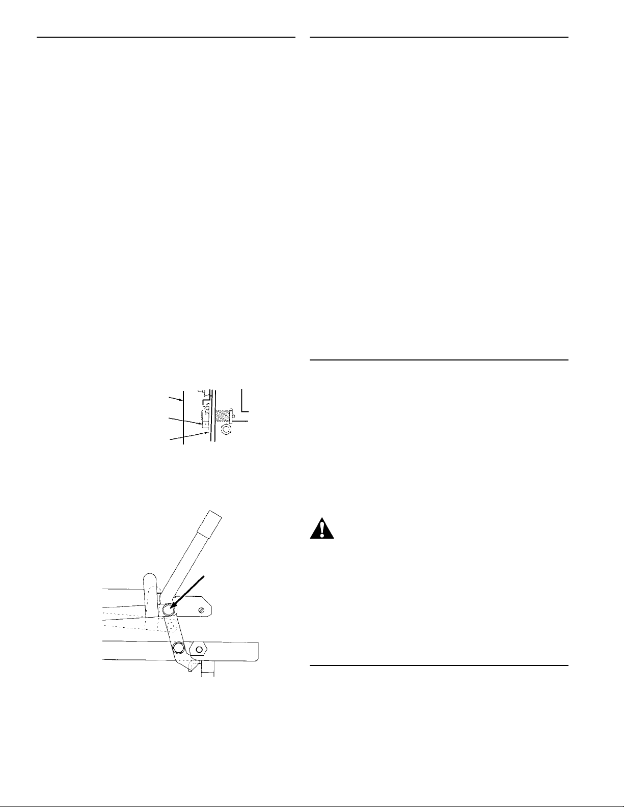
5. Ensure the stop blocks are set on the correct
setting for the size bun you are toasting. Improper
stop block setting results in lighter or darker
toasted buns or crushed buns.See figure 1.
IMPORTANT: To change stop block setting, depress
the right stop block to disengage locking pin and turn in
either direction.
OPERATION
1. Place (6) crowns face down on bun spatula.
2. Place (6) heels face up on bun tray.
3. Place (6) clubs on bun spatula.
4. Lift upper bun board and insert spatula with crowns
5. Lower bun board down on top of spatula. Slide
spatula out.
6. Insert spatula with clubs into center compartment.
Slide spatula out.
7. Insert the tray with heels into the lower compartment
of toaster.
8 Pull handle/lever assembly forward and down on top
of heels. This will activate the timer assembly.
9. When the buzzer sounds, immediatly push handle up
and back to release heels from heating platen.
Remove tray with heels from toaster.
10. Lift upper bun board and slide spatula in under the
crowns. Remove spatula with crowns from toaster.
11. Slide spatula into center compartment. Remove
spatula with clubs from toaster.
CLEANING
figure 1
LEFT SIDE PANEL
STOP BLOCK
PIN STOP BRACKET
6. Unlock handle by moving safety latch from the
locknut to the safety latch park nut. See figure 2.
figure 2
SAFETY LATCH
LOCKED
POSITION
BEARING STUD
UNLOCKED
POSITION
1. Unplug toaster and allow it to cool down.
2. Shake a small amount of cleanser on platen.
3. Dampen toaster platen cleaning pad and wipe off
top and bottom of platen.
IMPORTANT: Using a cleaning pad other than the
one provided may be too abrasive and take off the
nickel plating, causing buns to stick. Replacement
pads should be purchased from your local Prince
Castle Service Center. Order part #167-2.
CAUTION: Do not pour water on the
platen. This may cause an electrical
hazard and damage switches, linkage,
etc., voiding the warranty.
4. Starting from the center, proceed to clean platen by
wiping in a front to back motion with grain of platen.
5. Using a moist cloth, wipe off platen to remove all
cleaning materials.
6. After cleaning season toaster platen with a light
coat of shortening.
MAINTENANCE
IMPORTANT: To convert a 35 second toaster to a 55
second toaster, turn 35-55 second time select switch,
located underneath lower electrical box, to 55 second
position. Recalibrate temperature on both platens from
(216° +/- 3°C) to (204° +/- 3°C).
Under normal conditions with proper use and cleaning,
very little nonscheduled maintenance will be required
for this toaster. However, this section provides procedures to check or replace various parts within the
toaster. Before replacement of any parts refer to the
troubleshooting section for assistance in determining
the cause of malfunction.
2
Page 3
GENERAL INSTRUCTIONS
When disconnecting electrical wires, mark them in
some way that will indicate which terminal they
came from. Do not disconnect too many electrical
connections at one time. Refer to the individual
wiring diagram for particular controls that need
repair.
There are 3 basic methods of affixing wires to their
terminals.
1. Closed eye
2. Spade
3. Knife and blade
IMPORTANT: Do not wrap a bare wire under a terminal head screw.
Before attempting to repair a toaster:
1. Disconnect electrical supply.
4. Remove thermostat bulb retainer from electrical
box.
5. Remove thermostat and sensing bulb.
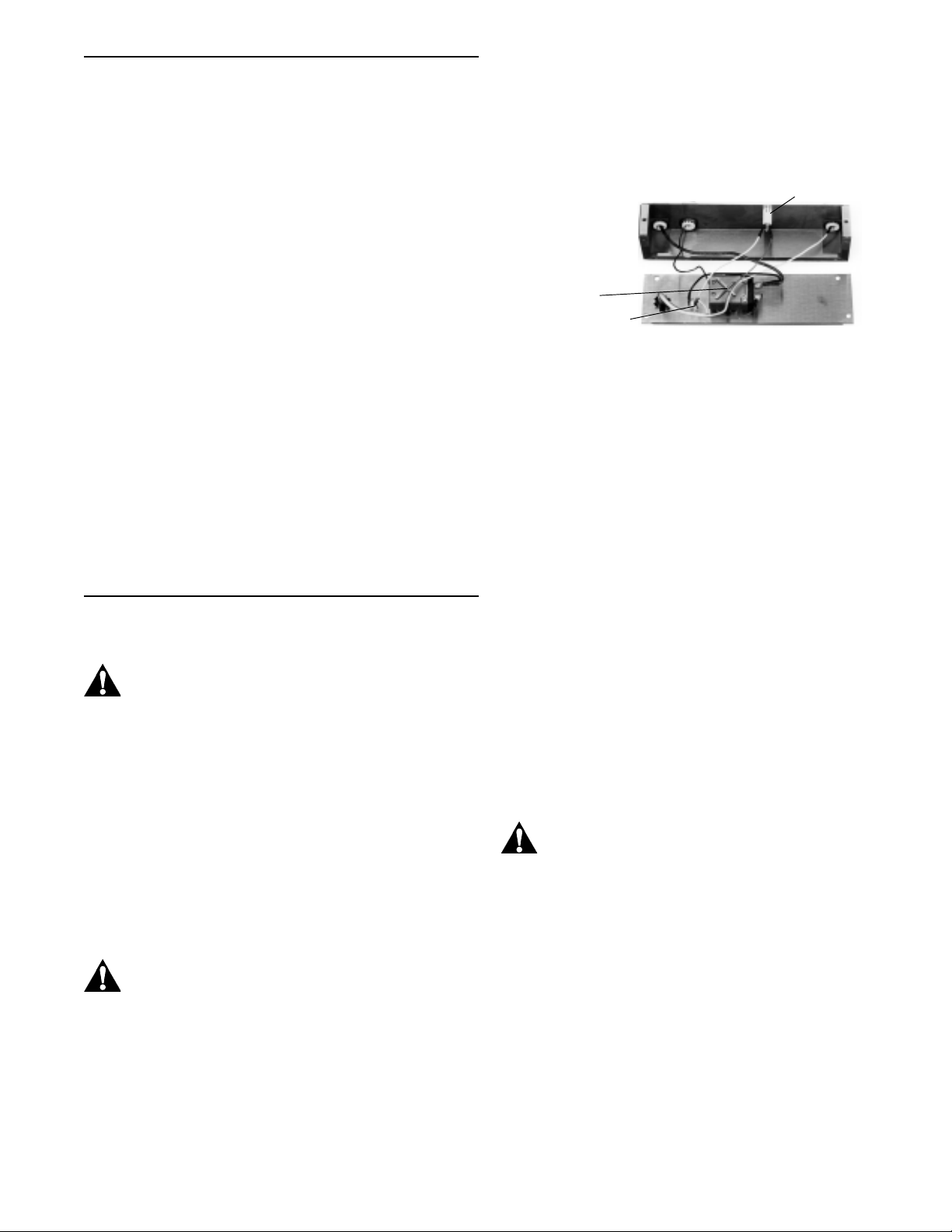
figure 3
AMBER BUN READY LIGHT
THERMOSTAT
WHITE CYCLE LIGHT
IMPORTANT: Replace with new thermostat by reversing procedure. Make sure to coat new thermostat bulb
with thermo-coat provided.
2. Permit the unit to cool completely.
IMPORTANT: Make good use of the parts pictures in
this chapter for further aid in understanding the physical make-up of your toaster and the reassembling of its
components.
ELECTRICAL REPAIRS
CAUTION: Before any electrical repairs,
place power switch in OFF position and
unplug toaster.
When replacing any electrical controls mounted in
control boxes, disassemble the following.
1. Remove (2) screws from upper or lower cover.
2. Remove cover(s).
3. Remove (5) screws from upper or lower faceplate.
REPLACE PLATENS
CAUTION: This procedure should be down
by a qualified service person.
REPLACE THERMOSTAT (See figure 3.)
HOW TO CALIBRATE TEMPERATURES
Tools Required Flatblade screwdriver
Digital thermometer
with surface probe
Stopwatch
1. Plug toaster in and turn the power switch to ON.
Allow 45 minutes for the platen temperature to
stabilize.
2. Place the surface probe of the digital thermometer
in the center of the top platen.
IMPORTANT: The temperature should be at 216° C
(+/- 3° C) when the temperature light goes off.
3. Repeat step 2 by placing the surface probe in the
lower platen.
CAUTION: Toaster must be hot to check
temperature calibration. Special care must
be taken to prevent being burned.
If the temperature is not within the range:
4. Turn the outer temperature shaft in the rear of the
toaster. (Turn shaft clockwise to increase and
counterclockwise to decrease platen temperature.)
IMPORTANT: A 1/4 turn will change the temperature
approximately 47° C.
Tools Required Flatblade screwdriver
1. Remove knob.
2. Remove (2) screws that hold thermostat to rear
cover.
3. Remove (2) wires from thermostat terminals.
5. Allow 20 minutes for the platen temperature to
stabilize before readjusting.
6. Adjust the thermostat dial plate so the correct
temperature is in line with the pointer on the
thermostat knob.
3
Page 4
LOWER ELECTRICAL BOX
HOW TO REPLACE LIGHTS
1. Locate inoperable light.
2. Disconnect (2) wires from the light.
3. Remove the light by pressing the bezel clips in and
pulling the light away from the control panel.
4. Reverse procedure to install new light.
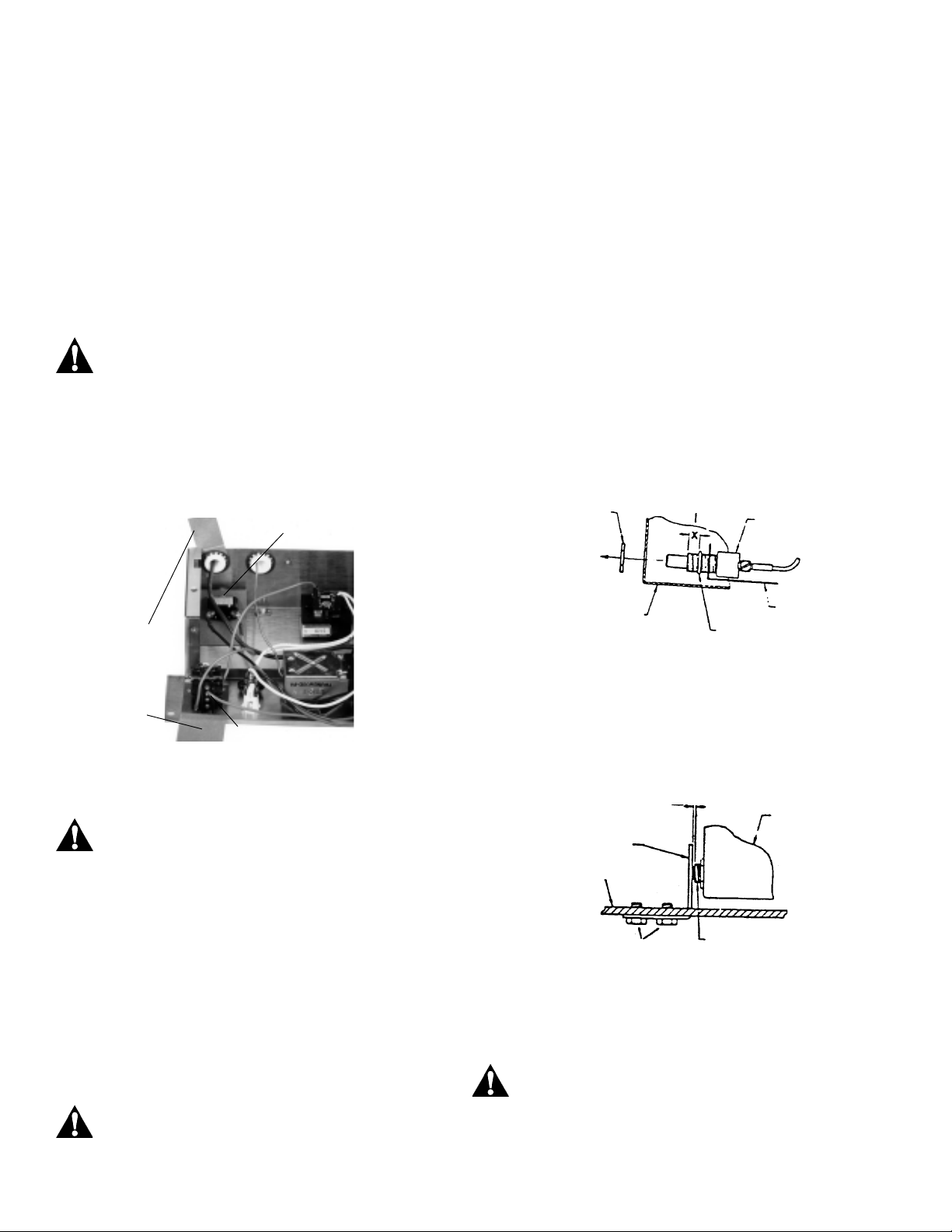
REPLACE RELAY
(See figure 4.)
Tools Required Flatblade screwdriver
CAUTION: This procedure should be performed by a qualified service person.
1. Remove screw holding relay to back cover.
2. Remove red wire from timer.
3. Remove red wire from buzzer.
figure 4
TIMER
SWITCH
ADJUST TIMER SWITCH
Tools Required Adjustable wrench
1. Position retaining ring on new switch 1/4” (6 mm)
from end of bushing.
IMPORTANT: Insulator should be placed between
switch body and retaining ring. See figure 5.
2. Set stop blocks at lowest position.
3. Slowly lower platen and watch movement of new
switch against actuator bracket.
IMPORTANT: When platen is all the way down, there
should be no more than 1/32” (1 mm) clearance between threaded switch bushing and actuator bracket.
IMPORTANT: The threaded switch bushing must not
press against the actuator bracket.
figure 5
RETAINING NUT
1/4” (6 mm)
SWITCH BODY
INSULATOR
INSULATOR
RELAY
4. Remove red wire from time switch.
5. Replace relay by reverse procedure.
CAUTION: Be sure insulator is between the
relay and rear cover.
REPLACE TIMER SWITCH
Tools Required Adjustable wrench
1. Remove 2 wires from timer switch.
2. Unscrew retaining nut on front of electrical box.
3. Remove switch.
4. Reverse procedure to install new timer switch.
CAUTION: Be sure insulator is between
switch and chassis.
ELECTRICAL BOX
RETAINING RING
INSULATOR
To adjust actuator
bracket, loosen mounting screws and move bracket
until 1/32” (1 mm) clearance is attained as shown in
drawing below. Retighten actuator bracket mounting
screws when bracket is positioned. See figure 6.
figure 6
ACTUATOR BRACKET
TOASTER FRAME
MOUNTING SCREWS
1/32” 1 mm
TREADED SWITCH BUSHING
ELECTRICAL BOX
REPLACE TIMER ASSEMBLY
Tools Required Adjustable wrench
Flatblade screwdriver
CAUTION: This procedure should be performed by a qualified service person.
1. Remove (2) wires from timer assembly.
2. Remove screw and nut holding timer assembly to
lower electrical box.
4
Page 5

3. Replace with new timer assembly by reversing
procedure. See figure 7.
2. Disconnect green/yellow ground wire from the power
switch.
figure 7
TIMER ASSEMBLY
THERM OSTAT BULB RETAINER
THERMOSTAT
LOWER ELECTRICAL BOX
REPLACE POWER SWITCH
Tools Required Adjustable wrench
1. Remove the nut that holds switch and switch plate
to cover.
2. Remove wires from switch.
3. Remove switch.
4. Replace by reversing steps 1-3 with new switch.
3. Remove power cord from lower chassis by removing
strain relief.
4. Reverse procedure to reinstall power cord.
REPLACE BUZZER
CAUTION: This procedure should be done
by a qualified service person.
1. Remove buzzer by holding ring and unscrewing.
2. Remove (2) wires from buzzer terminals.
3. Replace by reversing procedure.
CLOSING
CAUTION: Before unplugging, make sure
toaster is turned OFF.
1. Place the power switch in the OFF position.
2. Unplug toaster.
3. Allow toaster to cool.
4. Follow cleaning instruction on MRC 16.
CAUTION: This applieance is not watertight. Do not immerse in water or clean with
a water jet/jet spray.
REPLACE POWER CORD
Tools Required Flatblade screwdriver
CAUTION: This procedure should be done
by a qualified service person.
1. The power switch will have to be removed to get at
the (2) heavy power cord wires connected to the
bottom terminals. See figure 8.
figure 8
BUZZER
POWER CORDPOWER SWITCH
ORDERING/SERVICE INFORMATION
1. WHERE AND HOW TO ORDER
REPLACEMENT PARTS
To order replacement parts, look on the back of your
Prince Castle Price List for the name and phone
number of your local Prince Castle Service Center.
You may also call Prince Castle at 1-800-323-2930
(or fax us at 630-462-1460) for the name of your local
Service Center.
2. PARTS RETURNS
To return parts to your Service Center for credit, you
must obtain authorization from your Service Center.
iMPORTANT: All warranty situations should be handled
by your center.
5
Page 6

3. PRICES:
A. All prices are F.O.B. Prince Castle Service
Center or F.O.B. factory, Carol Stream, Illinois.
B. All prices are subject to change without notice.
These prices are exclusive of all sales taxes or any
special taxes which may be levied by federal, state,
or city governments.
OUTSIDE THE U.S.
Contact your kitchen equipment supplier or designated
repair facility for parts and service.
TROUBLESHOOTING GUIDE
CAUTION: Inspection,testing and repair of
electrical equipment should be performed
only by qualified service personnel.
PROBABLE CAUSEPROBLEM
Platen sways. Platen attachment bolts loose. Tighten bolts.
Buzzer works, but Light burned out. Replace bun ready light. See Maintenance.
no amber bun ready
light.
No buzzer or amber Defective timer switch. Replace timer switch. See Maintenance.
bun ready light. Defective timer assembly. Replace timer assembly. See Maintenance.
Timer switch out of adjustment. Adjust timer switch stroke. See Maintenance.
Defective relay. Replace relay. See Maintenance.
Amber bun ready Buzzer burned out. Replace relay. See Maintenance.
light goes ON but
buzzer does not work.
Buns being over Stop blocks not adjusted properly. Adjust stop blocks.
crushed. Warped bun trays. Straighten bun trays.
Buns cut improperly. Contact bakery.
Bun platform warped. Straighten bun platform.
Platen does not No power. Check power source.
heat. Power switch defective. Replace power switch. See maintenance.
Loose wiring. Correct as neccessary. See MRC 17.
Defective thermostat. Replace thermostat. See maintenance.
Platen burned out or shorted. Replace platen. Call Service Agency.
CAUTION: The unit should be unplugged
when servicing, except when electrical tests
are required. Use care when running tests.
CORRECTIVE ACTION
Buns sticking to Excessive heat. Recalibrate thermostat.
platen. Build-up of caramelized sugar on platen. Clean platen.
One platen does not No power. Check circuit breaker since one half of 220 volt
heat and one platen service may be out.
does. Power switch defective. Replace power switch. See maintenance.
Loose wireing. Correct as necessary.
Defective thermostat. Replace thermostat. See maintenance.
Platen burned out or shorted. Replace platen. Call Service Agency.
Bad connection in toaster plug. Tighten connection in plug.
Timer Assembly Timer Assembly set incorrectly. Check position of time select switch. Set it at
sounds at 55 seconds.
seconds. Recheck time.
6
Page 7

EXPLODED VIEW
7
Page 8

PARTS IDENTIFICATION/FUNCTION
PART
ITEM
1 416-576 Upper Faceplate 1 Part of electrical box operating panel for upper platen
2 411-353 Brkt. Cord Grip-Unthreaded 2 Secures flex wire to upper and lower enclosure.
3 89-093 Screw 4 Secures flex wire to upper and lower enclosure.
4 222-122A Thermostat 2 Temperature control for upper and lower platen.
5 222-102S Knob 2 Used to adjust thermostats.
6 222-91 Dial Plate 2 Plate with temperature readings used to calibrate
7 71-134-2 White Cycle Light 2 Goes ON when electrical power is being supplied to
8 416-574 Upper Chassis 1 Part of upper electrical box enclosure needed for
9 213-364 Platen Tube 3 Insulators that protect heating element connectors
10 89-135 Retainer 3 Holds thermo-break tumbes in place.
NO.
DESCRIPTION
QTY.
temperature.
heater.
operating controls.
and thermostat capilary tube.
FUNCTION
11 416-157 Platen Terminal Insulator 4 Protects the heating element connectors from
shorting against metal.
12 416-135 Thermostat Bulb Retainer 2 Holds thermostat capillary bulb in platen.
13 71-134-1 Amber Bun Ready Light 1 Lights when toasting cycle has completed
14 416-121 Upper Cover 1 Allows access to upper electrical box. (removabable)
15 416-689 Lower Faceplate 1 Part of lower electrical box that holds power switch, son-
alert, thermostat, heating light, power light and relay assy.
16 78-166S Power Switch 1 Provides electrical power to toaster when switch
is in the ON position.
19 72-196S Power Cord w/Plug 1 Provides electrical power to the toaster from the store’s
88-566 Plug Only (Europe Only) power outlet.
20 66-045 Strain Relief 1 Secures power cord to toaster face plate.
21 416-128 Lower Electrical Box Cover 1 Allows access to lower electrical box. (removable)
22 222-140 Muffler Cap 1 Reduces sound level of the audioalarm.
23 88-150 Buzzer 1 Indicates when buns are done. (International)
24 71-134-3 Green Power Light 1 Indicates power to the toaster.
25 416-653 Rear Upper Stud 2 Holds upper platen to rear levers.
26 416-167S Relay Assembly 1 Activates buzzer.
27 416-150 Relay Insulator 1 Protects the relay and relay wires from touching metal.
8
Page 9

PART
ITEM DESCRIPTION
28 416-692S Flexible Wire Assembly 1 Provides electrical power to upper electrical box.
29 416-691 Lower Chassis 1 Part of lower electrical box which holds the power
30 78-146S Timer Switch Kit 1 Starts the timer for the toasting cycle.
31 416-43 Timer Switch Insulator 1 Protects the switch from touching metal.
32 416-259S Timer Assembly 1 Controls toasting itme (adjustable for either 35
33 77-039 Barrier Strip 1 One connector barrier strip where electrical ground
34 416-136 Insulator, Barrier Strip 1 Protects barrier strip and wires from touching metal.
35 416-802 Lower Left Bun Fence 1 Attached to the platen to prevent buns from falling
36 416-801 Lower Right Bun Fence 1 off the sides.
37 416-482 Bun Board 1 Used as a weight to compress the crowns to the
38 212-285 Support Stud 3 Holds upper and lower platens to front and rear levers.
39 416-629S Upper Platen Kit 1 Electrically heated toasting surface.
NO.
35/55 seconds. or 55 seconds.
QTY.
cord, barrier strip and timer assembly.
wires interconnect.
proper toasting height.
FUNCTION
40 416-847 Upper rear bun fence 1 Attaches to platen to prevent buns from falling back.
41 416-829 L.H. Upper Bun Fence 1 Attached to platen to prevent buns from falling off sides.
42 416-830 R.H. Upper Bun Fence 1 Attached to platen to prevent buns from falling off sides.
43 416-625S Lower Platen 1 Electriclly heated toasting surface.
44 416-762 Lower Rear Bun Fence 1 Attaches to platen. Prevents buns from falling off the rear.
45 416-661 Upper Bun Catcher 1 Prevents buns from falling under toaster.
46 212-283 Spacer 6 Maintains alignment of levers with platen.
47 416-652 Rear Upper Spacer 2 Maintains alignment of levers with platen.
48 416-856S Rear Lower Lever 2 Holds the rear platen in the toaster and allows for
Assy. opening and closing of the toaster.
50 416-680S Base w/feet 1 Support for the toaster.
52 416-654 Rear Lower Stud 2 Holds lower platen to rear levers.
53 213-304 Safety Latch Stud 1 Safety latch engaged attachment location.
54 416-413 Front Lever Assy. 2 Holds the platens in the toaster and allows for
opening and closing of the toaster.
55 416-858S Rear Upper Lever Assy. 2 Holds the rear of platens in toaster and allows for
opening and closing of toaster.
56 416-581 Side Panel Assembly 2 Mounts to the frame to protect hands from getting
inbetween the platens.
57 416-651 Shim 1 Maintains alignment of latch.
58 416-488 Safety Latch 1 Holds platen in the open (up) position.
9
Page 10

PART
ITEM DESCRIPTION
59 81-013 Spring 2 Helper springs to reduce lifting force.
60 416-29 Stop Block Rod 1 Holds the stop blocks to the toaster frame.
61 416-489 R.H. Stop Block 1 Adjusts the height of the platens. 6 stop positions.
62 81-009 Stop Block Compression 1 Holds stop blocks in position.
63 79-105 Spacer 2 Locates position of stop blocks to front levers and
64 213-414 Actuator Bracket 1 Activates the toasting itmer when platens are closed.
65 68-001 Roll Pin 1 Locks compression spring in place.
66 212-284 Bearing Stud 4 Holds the front and rear links to the toaster frame.
67 89-959S Rubber Foot 4 Keeps toaster from moving while operating.
69 62-024 Bearing 2 Aligns bearing studs in handle lever assemblies.
70 416-648 Safety Latch Pin 1 Attachment point for safety latch.
71 213-302 Safety Latch Label 1 Instructs operator to engage the safety latch when
NO.
Spring
QTY.
holds the compression spring in position.
cleaning the toaster.
FUNCTION
72 416-490 L.H. Stop Block 1 Adjusts heights of platen’s 6 stop positions 35/64”
(14 mm) to 111/64” (29 mm).
73 416-683 Detent Pin 1 Holds the stop block at the chosen position.
74 416-657 Safety Latch Stop Bracket 1 Attaches bearing studs in handle and lever assemblies.
75 62-021 Bearing 2 Alligns bearing studs in handle and lever assemblies.
76 62-005 Bearing 10 Alligns bearing studs in handle and lever assemblies.
77 66-037 Bushing, Strain Relief 1 Secures power cord to toaster frame.
(200V & 220V)
10
Page 11

HARDWARE USED FOR MOUNTING PARTS
PART
ITEM DESCRIPTION
A 76-300 Screw, Pan Head 8-32 X 1/4” (6 mm) 4
B 76-300 Screw, Pan Head 8-32 X 1/4” (6 mm) 2
C 76-051 Screw, Binder Head 6-32 X 3/8” (10 mm) 1
D 76-040 Screw, Binder Head 10-32 X 3/8” (10 mm) 25
E 76-079 Screw, Binder Head 10-32 X 5/8” (15 mm) 2
F 76-043 Screw, Binder Head 8-32 X 1/4” (6 mm) 1
H 76-179 Screw, Binder Head 10-32 X 3/8” (10 mm) 16
NO.
79-031 Lock Washer 2
79-033 Washer #6 2
79-031 Lockwasher #8 1
73-021 Nut, Hex 8032 1
NSF-Dry Lube
QTY.
K 76-327 Screw, Pan Head, 8-32 X 1-1/4” (32 mm) 1
73-013 Nut, Hex Self-Locking 4-40 1
L 73-039 Nut, Hex 3/8-24 1
M 76-343 Set Screw, 10-32 X 3/4” (18 mm) 2
N 73-016 Nut, Hex 3/8-24 4
P 76-382 Screw, Hex Head 1/4 X 9/16” (14 mm) 4
R 76-619 Screw, Hex Head 1/4-20 X 3/8” (10 mm) 2
S 76-095 Screw, Binder Head 6-32 X 1/4” (6 mm) 4
T 88-416 Cable Tie 1
V 76-619 Screw, Hex Head 1/4-20 X 3/8” (10 mm) 2
79-028 Lockwasher - 1/4” (6 mm) 2
79-032 Washer, Flat 1/4” (6 mm) 2
W 79-144 Washer, O.D. 1.093 1
11
Page 12

WIRING INFORMATION
IMPORTANT ELECTRICAL INFORMATION
This unit’s power cord has International colored wires, which are different from Domestic.
Blue = Neutral
Brown = Hot
Green/Yellow = Ground
Black = Hot
12
 Loading...