

Page 1
OPERATING
INSTRUCTIONS
TABLE OF CONTENTS PAGE
Universal Toaster
Model No. 411-SL Series
Installation..................................................................... 2
Operating ....................................................................... 4
Troubleshooting ............................................................ 5
Self-Diagnostic Troubleshooting ................................. 6
Non-scheduled Maintenance ....................................... 7
Parts List..................................................................... 10
Exploded View ............................................................ 11
Wiring Diagram ........................................................... 12
LIMITED WARRANTYLIMITED WARRANTY
LIMITED WARRANTY
LIMITED WARRANTYLIMITED WARRANTY
This product is warranted to be free from defects in
material and/or workmanship for a period of two (2)
year from date of original installation, not to exceed
30 months from date of shipment from our factory.
Any component which proves to be faulty in material
and/or workmanship will be replaced or repaired (at
the option of Prince Castle, Inc.) without cost to the
customer for parts or labor.
This warranty is subject to the following exceptions/
conditions:
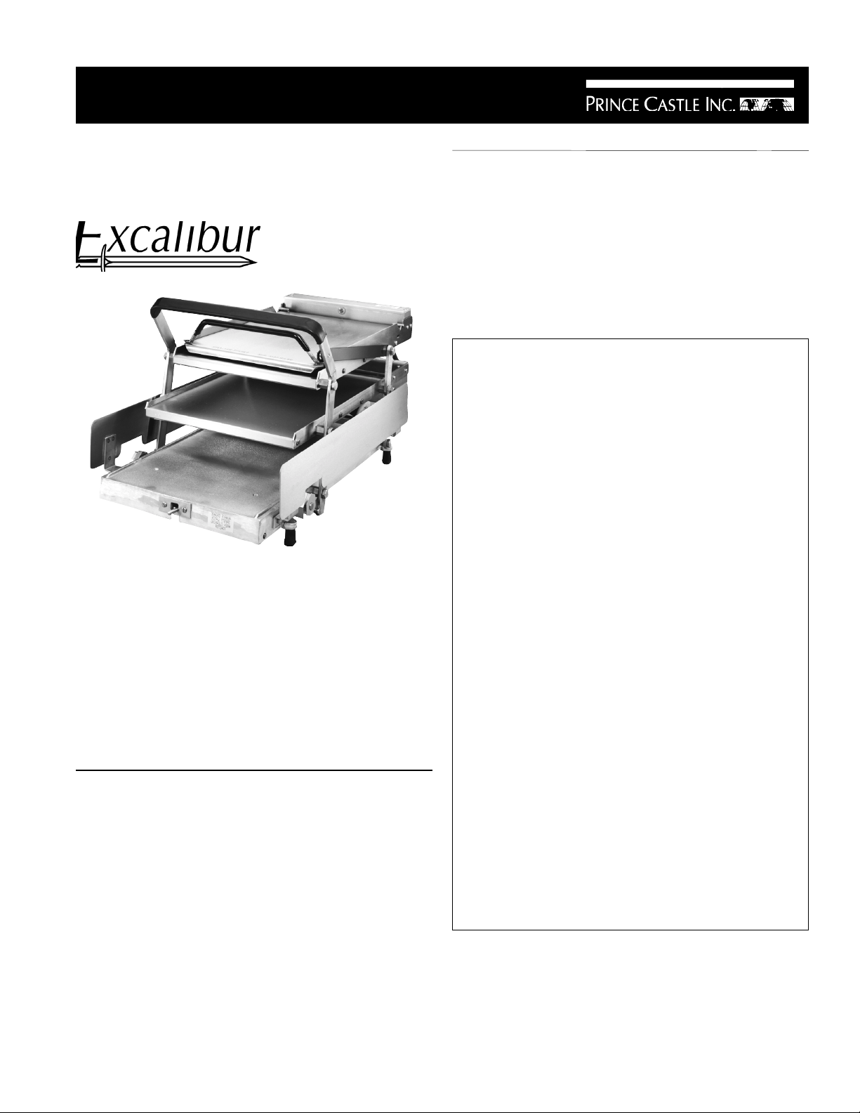
Prince Castle's Universal Batch Bun Toaster caramelizes
up to 12 regular 4" (10.16 cm)buns at one time. Perfectly
toasts two and three-part buns by allowing operators to
adjust time and temperature selections. Constructed of
durable stainless steel and aluminum, the 411-SL toaster
features a self-diagnostic trouble shooting system and
solid state controls and both audio and visual alarms.
Two nickel-plated platens offer precise temperature
control with superior and consistent toasting results. A
stainless steel bun board makes bun removal easy.
PRODUCT SPECIFICATION
Dimensions
Height Open: 15” (38.1 cm)
Height Closed: 7” (17.7 cm)
Width: 16-1/4” (41.2 cm)
Length Open: 35-1/4” (89.5 cm)
Length Closed: 31-1/2” (80.0 cm)
! Use of non-genuine Prince Castle Parts voids
this warranty.
! This equipment is portable; charges for on-loca-
tion service (e.g., trip charges, mileage) are not
included in the provisions of this warranty.
! All labor shall be performed during regular work
hours. Overtime premium will be charged to the
buyer.
! All problems due to operation at voltages other
than specified on toaster nameplates.
! This product must be serviced by a Prince Castle
Authorized Service Center or a Prince Castle
Factory Service Technician. Failure to do so
may void this warranty.
! Damage caused by carelessness, neglect, and/
or abuse (e.g., dropping, tampering or altering
parts), equipment damaged in shipment, by fire,
flood or an act of God is not covered under this
warranty.
Printed in December 1997
Prince Castle Inc.
355 East Kehoe Blvd. ! Carol Stream, IL 60188
Tel: (630) 462-8800 ! Fax: (630) 462-1460
Toll Free: 1-800-PCASTLE
411-506
Page 2
INSTALLATION
1. After you have removed the toaster from the carton,
inspect the unit for signs of damage. If there is
damage to the unit:
figure 3
! Notify carrier within 24 hours after delivery.
! Save carton and packing materials for inspection
purposes.
! Contact the Prince Castle Customer Sales
Department at 1-800-722-7853 to arrange for
a replacement to be sent.
2. Verify that all parts have been received.
3. If you find a part missing call 1-800-722-7853 and
ask for the Customer Sales Department. If you
have a question with operation ask for the Service
Department.
4. Toaster must be cold before Teflon release sheets
can be installed.
IMPORTANT: Toaster must be locked in the open
position by engaging the safety latch so toaster cannot
be closed before installing the Teflon release sheet.
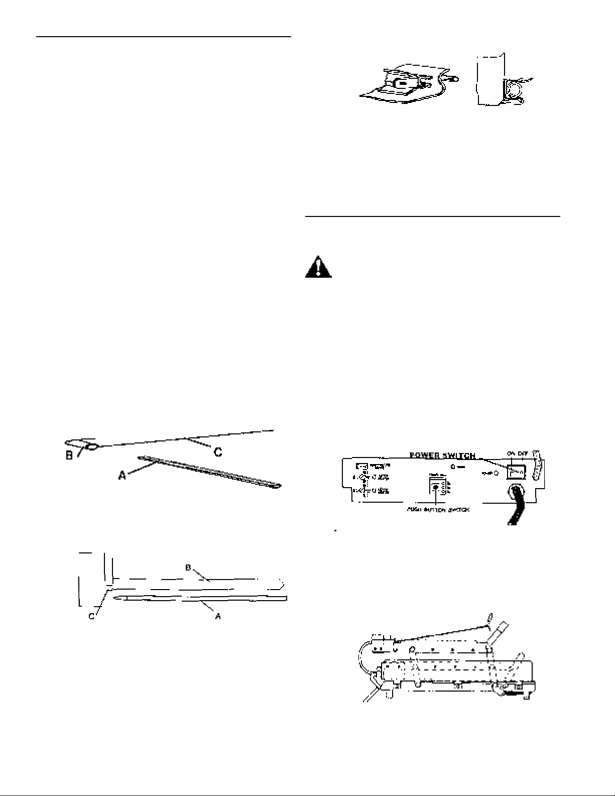
5. Install the stretcher bar (A) into the loop (B) of each
release sheet (C). See figure 1.
figure 1
IMPORTANT: The release sheet should be tight to the
bottom of the platen. If not, remove round bar and
repeat step 5.
9. Repeat steps 3-6 to install the release sheet on
upper platen.
OPERATION
CAUTION: Before plugging in, make sure
toaster power switch is in the OFF position.
1. Insert the power cord into an ANSI 125/250 volt, 3
pole 4 wire grounding outlet. The receptacle should
be a type NEMA #L14-20R. For European units the
receptacle should be a MENNEKES #316 P6 1302.
IMPORTANT: This should be a dedicated outlet. No
other equipment should be operating on this line (i.e.
fryers, refrigerators, cash registers, etc.).
2. Place the power switch in the ON position.
See figure 4.
6. Slide release sheet (A) to rear of bottom platen (B)
and attach to hooks (C). See figure 2.
figure 2
IMPORTANT: Slots in the stretcher bar are to face the
front of the toaster.
7. Pull the release sheet tight against the bottom of
the platen and spring retainer on the front of the
platen.
8. Push round bar and release sheet into the spring
retainer. See figure 3.
figure 4
3. Platens must be in the “UP” position while the
toaster warms up so that the timer is not activated.
Warm-up takes 30 minutes. See figure 5.
figure 5
2
Page 3
SETTING TOAST TIMES (See figure 6.)
SETTING TOAST TEMPERATURES
(See figure 7.)
figure 6
D
TIMER
55 Sec
45 Sec
35 Sec
B
POWER
TEMPERATURE
PROBE
TIMER ADJ
UPPER
HEATER
LOWER
HEATER
C
A
The toaster is preset at the factory for a 35 second
toasting time and a 420° F toasting temperature on
both platens. Temperature settings using commercial
bakery buns are:
35 seconds 420° F
45 seconds 410 ° F
55 seconds 400° F
Settings may have to be adjusted because sugar within
the product being toasted may vary from bakery to
bakery.
1. On the lower control box panel, locate and lift the
sliding door marked TIMER ADJ (A). Behind the
door are three red LED’s (B) each denoting a bun
toasting time setting of either 35 sec, 45 sec or 55
sec.
IMPORTANT: There should be only one time setting
light on.
2. Behind the TIMER ADJ (A) door there is a small
PUSH BUTTON SWITCH (C). The bun toasting
time can be set or changed whenever the toasting
cycle is NOT active (i.e. when the red timer light
(D) is not lit).
3. Press and hold the TIMER ADJ (A) button in for 5
seconds until an audio alarm sounds. At this point
the next bun toasting time light will turn on. Release and press the TIMER ADJ (A) button until the
desired bun toasting time for your product is
selected.
4. Activate toaster timing cycle by pulling the handle/
lever assembly forward and down. After selected
time (35, 45, or 55 seconds) has elapsed the
audible alert will sound and the “bun ready light”
will come on.
figure 7
A
TEMPERATURE
PROBE
UPPER
HEATER
LOWER
HEATER
C
B
TIMER ADJ
TIMER
55 Sec
45 Sec
35 Sec
POWER
To properly calibrate and set cooking temperatures
the following tools are required:
! “K” Type Pyrometer
! Thermo - Electric Patch Cord #SF001-250
! Flat Blade Screwdriver
1. Locate the two yellow–colored temperature probe
jacks (A) on the upper and lower control boxes.
2. Plug one end of the Patch Cord into the temperature probe jack (A) of either the upper or lower
control box depending on which platen you are
calibrating first. Plug the other end of the patch
cord into the “K” type pyrometer.
3. Directly beneath the temperature probe jack (A) on
the lower control box are the two platen temperature control potentiometers (B), labeled upper adj
and lower adj for upper platen and lower platen.
Next to each temperature control potentiometer is a
yellow indicating light (C) (upper header and lower
heater). These indicating lights will be lit when
power is being supplied to the corresponding
platen. Thus these lights will cycle on/off as the
corresponding platen temperature is being controlled.
4. To set a temperature use the flat blade screwdriver
to turn the temperature control potentiometer (B).
Turning the pot clockwise will increase the platen
temperature counterclockwise to decrease.
5. Observe the potentiometers temperature display
and note the temperature at the point when the
Yellow heater indicator light (C) of the corresponding platen turns off. This temperature is considered
the calibration temperature.
IMPORTANT: Toasting temperatures will vary by bread
product so your calibrated temperature may vary for
different products.
6. Remove the patch cord from the toaster temperature.
3
Page 4
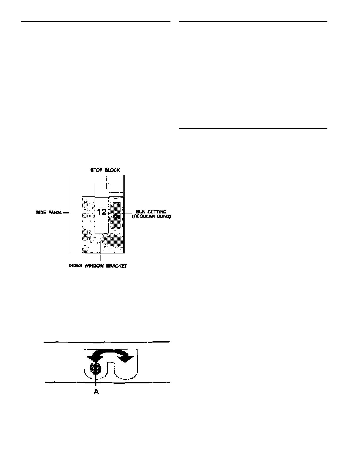
SETTING STOP BLOCKS (See figures 8 & 9.)
The stop blocks allow toasting different sizes, cuts and
brands of bread product. There are (6) combination
stop block settings in 1/16” increments. The overall
range is 3/4” to 1-1/4”. The stop block settings allow a
better crush when toasting different styles of buns.
1. Ensure stop blocks are on the correct setting
before operating toaster. There are (6) stop block
combinations available.
2. To change a stop block setting, depress the right
stop block to disengage locking pin and turn in
either direction to the desired setting.
3. View the stop block setting selected through the
index window bracket which is located over each
stop block. See figure 8.
CENTER OPENING ADJUSTMENT
To adjust the opening between the upper and lower
platens, loosen the two screws holding the adjustment plate on each side of the lower platen. There
are 11 adjustments. The middle adjustment is 1/2 ” .
Each adjustment moves the opening 1/16”. Moving
the adjustment plate to the left increases the opening, moving it to the right decreases the opening.
The center adjustment should be used when toasting different cuts of bread.
OPERATION
figure 8
4. Locate the selector lever (A) on the front of the
toaster frame and move the lever left or right to
allow you to switch back and forth between the
combination setting selected on the stop block.
See figure 9.
After selecting a cooking time and temperature, and
setting the stop blocks and the center adjustment
plate you are ready to begin toasting buns.
1. Using the bun spatula place the crowns face up.
2. Using the other bun spatula place the heels cut
face down.
3. Lift the bun board on the upper platen up and insert
the spatula with the heels on it.
4. Lower bun board down on top of heels and spatula
slide spatula out leaving heels on platen with bun
board on top.
5. Insert spatula with crowns on it into he center
section or lower section of toaster.
6. Pull toaster handle forward to move platen on top of
crowns, the timer will automatically activate and
the red timer light will come on.
7. When the audio alarm sounds and the bun done
light comes on, immediately push handle back to
release crowns from platen. Remove spatula with
crowns from toaster.
figure 9
8. Lift bun board on upper platen and slide the spatula
in under the heels and remove
4
Page 5

REMOVAL & CLEANING OF
RELEASE SHEETS
2. Rinse release sheets using clean running water
and wipe the sheets dry in one direction only
using a clean damp grill cloth until all residue is
removed. Do not fold or crease (air dry).
TO REMOVE:
1. Toaster must be cold before release sheets can
be removed.
CAUTION: Before removing release
sheets the toaster platen must be locked
in its open position by engaging the
“safety latch”.
2. Remove release sheets by removing the round
bar from the spring clip on the front of platens
and then remove the stretcher bar from rear
hooks.
3. Remove stretcher bar from release sheets.
TO CLEAN:
1. Lightly scrub the release sheet on both sides
using a damp clean towel. Keep sheet flat while
cleaning to ensure no wrinkles or creases are
put into sheet.
IMPORTANT: Do not use green pads to scrub
release sheets.
3. Rinse release sheets using clean running water
and wipe the sheets dry in one direction only
using a clean damp grill cloth. Keep wiping until
all residue is removed.
CLEANING
CAUTION: Before unplugging power cord
make sure the toaster power switch is
turned OFF.
1. Unplug toaster power cord from outlet.
2. Allow toaster to cool.
3. Follow cleaning instructions.
IMPORTANT: Always lock platens in open position
using the safety latch before cleaning or relocating
toaster to a different location.
IMPORTANT: When cleaning do not pour water on
the platen. This may cause an electrical hazard and
cause serious damage to the sensitive solid state
circuitry in this toaster.
TROUBLESHOOTING CHART
CAUTION: Service is to be performed by
qualified service personnel.
CAUTION: Use extreme caustion during
electrical ciruit tests. Live circuits will be
exposed.
PROBLEM PROBABLE CAUSE CORRECTIVE ACTION
Platen Has excessive movement. Platen attachment bolts loose. Tighten bolts.
Audio Alarm works, no amber Light burned out. Replace amber colored bun done
colored bun light. light.
No audio alarm or amber colored Speaker defective. Replace speaker.
bun done light. Opto sensor board defective. Replace opto sensor board.
Buns being crushed. Stop blocks not adjusted properly Adjust stop blocks.
Buns cut improperly. Adjust stop block to (=) or (-).
Buns sticking to platen. Excessive heat. Calibrate toaster.
Built up carmelized sugar on platen. Clean platen (PM Card #17).
One platen not heating but no Corresponding probe inoperable. Replace probe.
diagnostic signals.
5
CAUTION: Inspection, testing and repair of
electrical equipment should be performed
only by qualified service personne. The unit
should be unplugged when servicing, except
when electrical tests are required.
Page 6

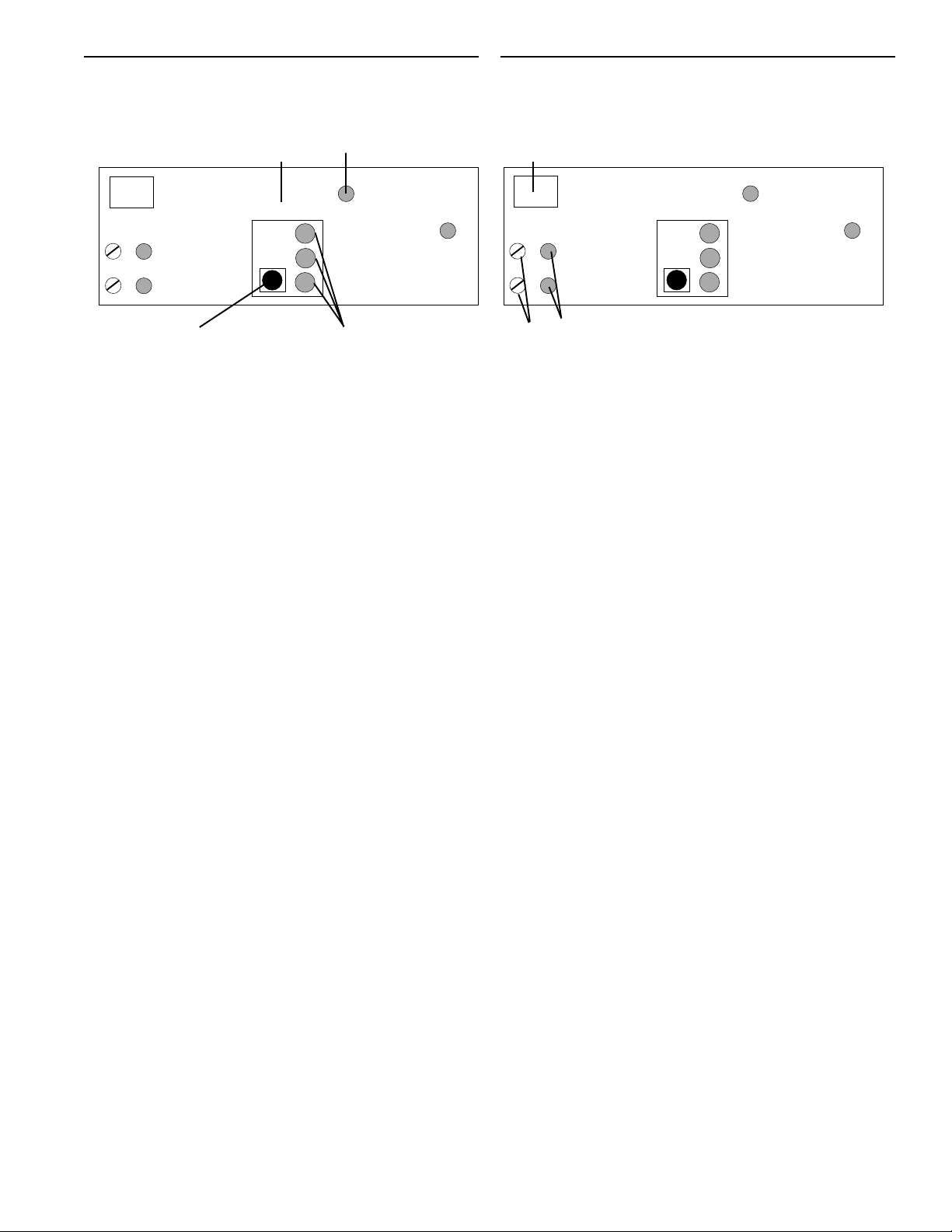
SELF-DIAGNOSTIC TROUBLESHOOTING CHART
Observe the (3) red indicator lights (A), and the (2)
LOWER CONTROL BOX FACEPLATE
yellow lights controlling the upper & lower heater
area (B). An audio alarm will sound, match the
lights in the malfunction section below to the toaster
TEMPERATURE
PROBE
malfunciton to identify the corrective action.
UPPER
Indicates red lights is on and flashing.
Indicates red lights is off.
Indicates red lights is off.
AREA B
HEATER
LOWER
HEATER
Yellow
Indicator
Lights
SELF-DIAGNOSTIC TROUBLESHOOTING CHART
For the five
malfunctions in
this column,
replace the 411261S Power
Board located in
the lower control
box.
UPPER
HEATER
LOWER
HEATER
UPPER
HEATER
LOWER
HEATER
TIMER ADJ
55 Sec
45 Sec
35 Sec
TIMER ADJ
55 Sec
45 Sec
35 Sec
Check the lower probe
connector at the main
P.C. Board. Replace
the 411-85S located in
the lower control box.
Check the upper probe
connection at the optosensor board located
in the upper control
box. Replace the 41185S located in the
upper control box.
TIMER ADJ
AREA A
UPPER
HEATER
LOWER
HEATER
UPPER
HEATER
LOWER
HEATER
TIMER
POWER
55 Sec
45 Sec
35 Sec
Red
Indicator
Lights
TIMER ADJ
55 Sec
45 Sec
35 Sec
TIMER ADJ
55 Sec
45 Sec
35 Sec
UPPER
HEATER
LOWER
HEATER
UPPER
HEATER
LOWER
HEATER
UPPER
HEATER
LOWER
HEATER
TIMER ADJ
TIMER ADJ
TIMER ADJ
55 Sec
45 Sec
35 Sec
55 Sec
45 Sec
35 Sec
55 Sec
45 Sec
35 Sec
Replace the No. 411262S Main P.C. board
located on the front
faceplate on the lower
control box.
If there is no timer or
heater lights on, but
the audio alarm is
sounding replace the
411-262S Main P.C.
Board.
If (3) timer lights are
flashing and an audio
alarm is sounding the
upper and lower
platens are over
heating. Turn the
toaster OFF and
disconnect the power
cord from receptacle.
UPPER
HEATER
LOWER
HEATER
UPPER
HEATER
LOWER
HEATER
UPPER
HEATER
LOWER
HEATER
TIMER ADJ
55 Sec
45 Sec
35 Sec
TIMER ADJ
55 Sec
45 Sec
35 Sec
TIMER ADJ
55 Sec
45 Sec
35 Sec
Then call the Prince Castle Service Department at 1-800323-2930 for assistance.
6
Page 7

NON-SCHEDULED MAINTENANCE
Model No. 411-14 Opto-Sensor P.C. Board
Tools Needed: 1/4” Flat blade screwdriver
Model No. 411-261S Power P.C. Board
Tools Needed: 1/4” Flat Blade Screwdriver
1. Disengage safety latch and lower toaster to toast
position. Using 1/4” flat blade screw driver remove
(2) screws (A) from cover (B) on the lower control
box, and remove cover. See figure 13.
1. With the toaster in the up position and the safety
latch in place use the flat blade screwdriver to
remove (7) screws (A) from the upper control box
and slowly lift up the back. See figure 10.
figure 10
2. Disconnect the (4) wire connectors (A) from the
P.C. Board (B). Using the flat blade screwdriver
remove (4) screws (C) holding the P.C. Board to
the standoffs (D) and carefully remove the P.C.
Board. See figure 11.
figure 11
figure 13
2. Carefully disconnect the wire connectors (A)
from the board, using the 1/4” flat blade screwdriver remove the (3) wire connections (B) from
the terminal black (C). See figure 14.
figure 14
3. Using the 1/4” flat blade screwdriver remove the
(2) screws and washers (A) that hold the power
board to the standoffs from the top of the power
board. Slide the P.C. Board out of the (2) rear
mounting brackets (B) and lift out of the control
box. See figure 15.
3. To install replacement Opto-Sensor P.C. Board
reverse steps 1 and 2. When reconnecting the
(4) wire connectors the RED connector goes into
PROBE slot on board, the 3 prong white connector goes into the done light slot on the board, the
2 pronged white connector goes into the speaker
slot on the board and the six prong maroon
connector goes into the main P.C. Board slot on
the board. Make sure all connections are tight.
See figure 12.
figure 12
figure 15
4. Reverse steps 1-3 to install the replacement
board. Be sure all wire connections are tight
and properly located.
7
Page 8

Model No. 411-262S Main P.C. Board
Model No. 411-85S Probe Assembly
Tools Needed: 1/4” Flat Blade Screwdriver
1. Disengage safety latch and lower toaster to toast
position. Using 1/4” flat blade screwdriver
remove (2) screws (A) from cover (B) on lower
control box, and remove cover. See figure 16.
figure 16
2. Using the 1/4” flat blade screwdriver remove (2)
screws (A) from the front of the lower control box
and carefully pull back faceplate exposing main
P.C. Board. See figure 17.
figure 17
Tools Needed: 3/16” Flateblade Screwdriver
1/4” Flatblade Screwdriver
Nut Driver 8-32
1. Using the 1/4” flat blade screwdriver remove (7)
screws (A) that secure the cover tot he control
box. See figure 20.
figure 20
2. Using a 3/16” flateblade screwdriver loosen the
(2) screws (A) that attach probe wires to the
yellow mini-jack (B) and remove the (2) wires
from this connection. See figure 21.
A
3. Disconnect the (5) wire connectors (A) from the
board. See figure 18.
figure 18
A
A
4. Using the 1/4” flat blade screwdriver remove the
(5) screws (A) from the front of the faceplate
which holds the board to the faceplate, and
remove the old board. See figure 19.
figure 19
figure 21
3. Unplug wire connector (A) from the probe (B) to
the printed circuit board (C). See figure 22.
figure 22
A
A
5. To install the new P.C. Board reverse steps 1-4.
Make sure all wire connections are tight.
8
Page 9

4. Using a nut driver remove nut (A) which secures probe
bracket (B) to screw (C) on the control box.
See figure 23.
figure 23
5. Remove probe bracket (A) and carefully slide probe (B)
out of the platen tube. Discard old probe assembly.
See figure 24.
figure 24
B
Model No. 78-166S Power Switch
Tools needed: 1/4” Flat Blade Screwdriver.
1. Lower toaster to toast position. Using 1/4” Flat
Blade Screwdriver remove (2) screws (A) from
the lower control box and lift off cover. See
figure 25.
figure 25
2. Disconnect (4) wire connections (A) from the
power switch (B). See figure 26.
figure 26
6. Install new probe by reversing steps 2 through 5. For
probe replacement in the lower control box follow these
same instructions.
3. Remove power switch by squeezing bezel clips
on switch (A) and pushing switch (B) out of the
control box. See figure 27.
figure 27
4. To install new power switch reverse steps 1-3.
Make sure all wire connections are
tight and on the right posts.
Top Left = Brown Wires
Bottom Left = Black Wire
Top Right = Double Black Wire
Bottom Right = Double Red Wire
9
Page 10

PARTS LIST
ITEM PART NO. DESCRIPTION
1 411-2S Base
2 89-959S Rubber Foot
3 411-243 Rear Lever Assy.
7 411-200 Safety Latch
8 411-238 Front Lever Assy.
9 411-118 Safety Latch Pin
10 411-8S Lower Platen
411-26S Lower Platen (220 Volt)
11 411-42 Lower Rear Bun Fence
12 411-44 Lower Left Hand Bun Fence
13 411-43 Lower Right Hand Bun Fence
14 411-70 Platen Tube
15 411-6S Upper Platen
411-24S Upper Platen (220 Volt)
16 411-254 Upper Rear Bun Fence
17 411-234 Upper Left Hand Bun Fence
18 411-223 Upper Right Hand Bun Fence
19 411-86 Spring Rod
20 81-013 Extension Spring
21 411-146 Guide Rod (Shaft)
22 411-108 Lever Block
23 89-925 Plunger Spring
24 411-107 Lever
25 411-117 Cover Plate
26 411-230 Left Hand Stop Block
27 411-231 Right Hand Stop Block
28 411-127 Index Window
29 411-123 Bun Tray Stop
30 411-256 Right Side Panel Assy.
31 411-41 Strain Relief Bracket
32 66-015 Strain Relief Bushing
33 72-126S Power Cord
34 411-257 Left Side Panel Assy.
40 411-77 Lower Chassis
41 411-80 Lower Face Plate Assy.
42 411-32 Potentiometer Bracket
43 411-133S Lower Potentiometer Assy.
44 411-132S Upper Potentiometer Assy.
46 411-261S Power P.C. Board
47 89-924 Standoff
48 77-058 Barrier Strip
49 411-85S Probe Assy.
50 213-166 Probe Retainer
51 411-31 Chassis Cover
52 411-262S Main P.C. Board
53 88-497 Mini-Jack
54 71-117 Clear Lens
55 78-166S Power Switch
56 411-69S Interconnect Cable
411-109S Interconnect Cable (220 Volt)
57 66-027 Aluminum Stain Relief
66-062 Strain Relief (220 Volt)
58 411-83 Cable Cord Bracket
59 89-938 Loop Steel Clamp
60 411-33 Door Plate
61 411-34 Door Guard
62 88-573 Cable Clamp
63 89-921 Nylon Spacer
65 411-72 Upper Chassis Assy.
66 411-74 Upper Face Plate
67 213-229 Speaker Assy.
68 482-18 Speaker Grease Seal
69 411-14S Sensor P.C. Board
70 213-257 Done Light Assy.
71 411-140 Insulator
A 411-59 Base Stud 5/16-18
411-113 Base Spacer
73-167 Self Locking Hex Nut 5/16-18
B 411-60 Lower Rear Platen Stud
411-57 Lower Platen Spacer
C 411-60 Upper Platen Stud
411-241 Safety latch Spacer
D 411-60 Upper Platen Stud
411-221 Upper Platen Spacer
E 76-218 Slotted Binder Head Screw 1/4-20
F 411-60 Lower Front Lever Platen Stud
411-57 Upper Platen Spacer
H 76-179 Slotted Binder Head Screw 10-18
J 76-382 Hex Head Screw 1/4 -20 x 3/8
K 76-343 Set Screw 10-32 x 3/4
L 68-039 Roll Pin
M 76-600 Slotted Flat Head Screw 10-24 x 1
73-008 Self Lock Hex Nut 10-32
N 76-040 Slotted Binder Head Screw 10-32
P 76-043 Slotted Binder Head Screw 8-32
R 76-095 Slotted Binder Head Screw 6-32
S 76-095 Slotted Binder Head Screw 6-32
79-002 Intl. Tooth Washer #6
T 76-044 Slotted Binder Head Screw 8-32
73-021 Hex Nut 8-32
U 76-095 Slotted Binder Head Screw 6-32
79-033 Split Lock Washer #6
73-031 Self Locking Hex Nut
V 76-043 Slotted Binder Head Screw 8-32
79-031 Split Lock Washer #8
73-021 Hex Nut 8-32
W 76-043 Slotted Binder Head Screw 8-32
79-143 Flat Washer
73-013 Self Locking Hex Nut
X 920-184 Hex Nut
79-144 Washer
Y 76-043 Slotted Binder Head Screw 8-32
73-013 Self Locking Hex Nut
AA 76-043 Slotted Binder Head Screw 8-32
73-013 Self Locking Hex Nut
BB 76-064 Slotted Binder Head Screw 8-32
73-021 Hex Nut 8-32
CC 76-043 Slotted Binder Head Screw
73-021 Hex Nut
DD 76-051 Slotted Binder Head Screw 6-32
73-015 Self Locking Hex Nut 6-32
EE 76-300 Slotted Pan Head Screw
72 411-233 Upper Bracket
Page 11

73 411-234 Upper Bracket
74 411-240 Front Bracket
75 212-622 Front Bracket
76 411-227 Platen Bracket
EXPLODED VIEW
77 411-228 Platen Bracket
78 411-239 Front Bracket
79 411-242 Teflon Holder
80 212-331 Platen Plate
UPPER CHASSIS ASSEMBLY
LOWER CHASSIS ASSEMBLY
Page 12

WIRING DIAGRAM
12
 Loading...