

Page 1

LIMITED WARRANTY
This product is warranted to be free from defects in material and/or workmanship for a period of (2) years
from date of original installation not to exceed 30 months from date of shipment from our factory. Printed
circuit boards and platen are warranted for a period of (3) years from date of original installation not to
exceed 42 months from date of shipment from our factory. Any part or component which proves to be
faulty in material and/or workmanship within the warranty period will be replaced or repaired without cost
to the customer for parts or labor. (At the option of Prince Castle, Inc.)
This warranty is subject to the following exceptions/conditions:
l Any use of Non-genuine Prince Castle spare parts voids this warranty, and all work must be per-
formed by an authorized Prince Castle Service Agent.
l All labor should be performed during regular working hours. Overtime premium will not be covered.
l Travel charges are limited to 100 miles (200 km) round trip, 2 hours travel time, one trip per repair.
l Damage caused by carelessness, neglect, and/or abuse (e.g., using wrong current, dropping, tam-
pering with or altering electrical components, or improper cleaning) is not covered.
l Equipment damaged in shipment, by fire, flood or an act of God.
This manual is for the exclusive use of licensees and employees of McDonald’s Systems, Inc.
Part No. 411-553
2003McDonald’s Corporation Printed in the
All Rights Reserved United States of America
This equipment chapter is to be placed in the
toasters section of your Equipment Manual.
MANUFACTURED FOR
MCDONALD’S®
BY
PRINCE CASTLE INC.
355 KEHOE BLVD.
CAROL STREAM, IL. 60188 USA
PHONE 1-630-462-8800
TOLL FREE NUMBER
1-800-323-2930
FAX:1-630-462-1460
SOLID STATE DIGITAL ENERGY SAVING TOASTER
PRINCE CASTLE MODEL NO. 411-SDFM4TCE SERIES
WARRANTY..............................................................................................................................................................................................Page 1
SIDE VIEW................................................................................................................................................................................................Page 2
FRONT VIEW............................................................................................................................................................................................Page 3
REAR VIEW..............................................................................................................................................................................................Page 3
INTERNAL VIEW.....................................................................................................................................................................................Page 4
EQUIPMENT SET-UP.............................................................................................................................................................................. Page 5
PROGRAMMING ...................................................................................................................................................................................... Page 6
CLEANING ................................................................................................................................................................................................ Page 8
TROUBLESHOOTING .............................................................................................................................................................................Page 8
WIRING DIAGRAM .............................................................................................................................................................................Page 9
FRENCH TRANSLATION.......................................................................................................................................................................Page 10
Page 2
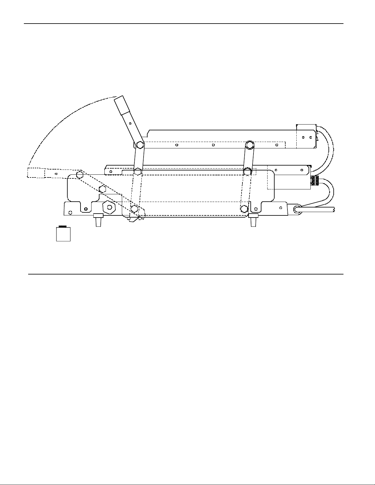
SIDE VIEW
PARTS LIST
ITEM PART NUMBER DESCRIPTION
1 411-149S Handle and Lever Assy.
2 411-441 Right Hand Upper Bun Fence
411-440 Left Hand Upper Bun Fence
3 411-461S Upper Rear Lever Assy.
4411-378Upper Rear Bun Fence
5411-381 Lower Rear Bun Fence
6411-459S Lower Rear Lever Assy.
7411-137 Right Hand Stop Block
411-138 Left Hand Stop Block
8411-692 Side Panel, Right Hand
411-257 Side Panel, Left Hand
9 411-379 Right Hand LowerBun Fence
411-380 Left Han
d Lower Bun Fence
10 78-232S Rotary Switch Timer Assy.
11 70-050S Knob
Not Shown 95-1312S Switch Cable Assy.
Not Shown 411-114 Safety Latch
Not Shown 411-744 Bun Board
1
23
5
6
7
8
9
2003 McDonald’s CorporationPart No. 411-553 Printed in the
All Rights Reserved United States of America
2
10
11
4
Page 3
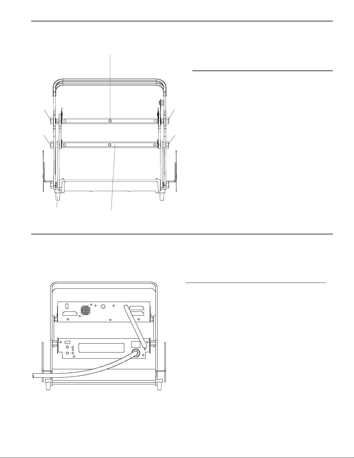
FRONT VIEW
PARTS LIST
REAR VIEW
ITEM PART NUMBER DESCRIPTION
1 411-483S Upper Platen 230V
2 411-60 Front Upper/Lower
Platen Stud
3 411-486S Lower Platen 230V
4 89-959S Foot (Pkg. of 4)
PARTS LIST
ITEM PART NUMBER DESCRIPTION
1411-147S Rear Upper
Platen Stud
2411-61S Rear Lower
Platen Stud
3411-707 Overlay
1
2
2
3
4
2
2
1
2
3
2
1
2003 McDonald’s CorporationPart No. 411-553 Printed in the
All Rights Reserved United States of America
3
Not Shown 212-491S Release Sheets (Pkg. 2)
Not Shown 411-239S Front Clip, Upper
Not Shown 411-240S Front Clip, Lower
Page 4
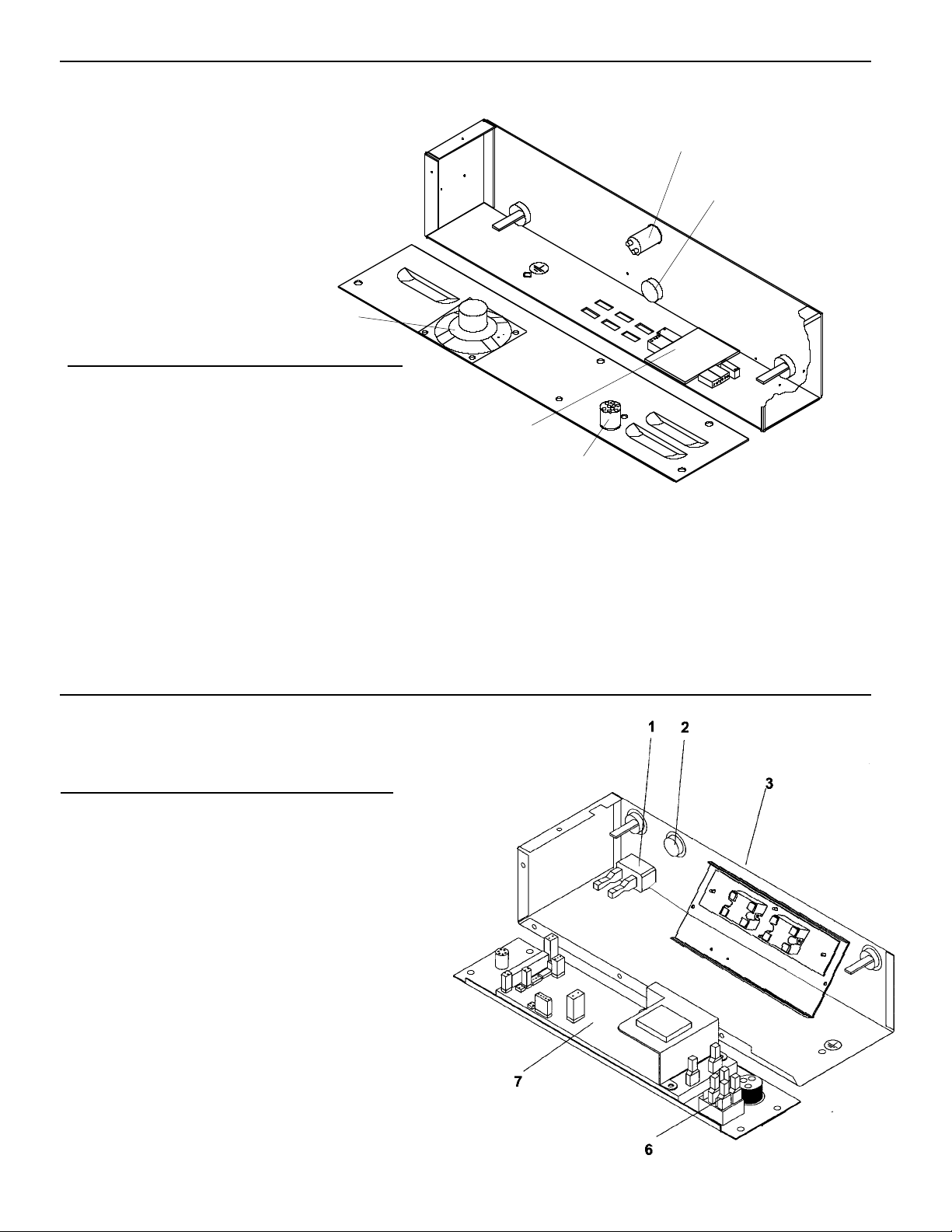
INTERNAL VIEW UPPER CONTROL BOX
PARTS LIST
INTERNAL VIEW LOWER CONTROL BOX
ITEM PART NUMBER DESCRIPTION
1 213-257S Bun Done Light
2411-731SUpper Probe
3 411-662S Interconnect Cable
4411-14SInterconnect Board
5735-61S Speaker
PARTS LIST
ITEM PART NUMBER DESCRIPTION
165-058SRelay, Lower & Upper
2411-731SLower Probe
4 78-166S Rocker Switch
5411-427-08SControl PCB 220-230V
1
2
3
4
5
2003 McDonald’s CorporationPart No. 411-553
All Rights Reserved
4
Printed in the
United States of America
4
5
1
Page 5

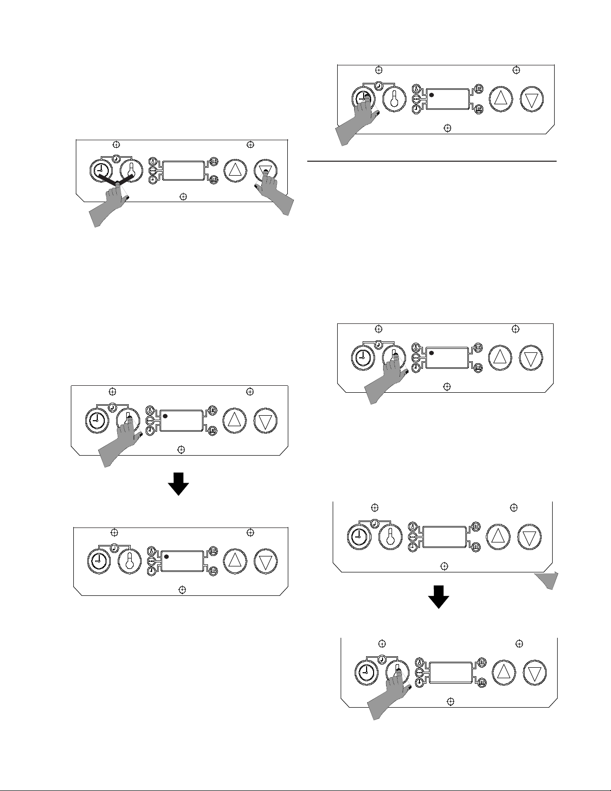
operating temperature.
2. The toaster is factory-set to display temperatures
reading in Celsius. When the toaster is turned on,
the digital display on the control box will read C--A
for Celsius, and the “A” will begin to count down 9
seconds. During this countdown, you can change
the temperature display from Celsius to Fahrenheit
readings. To change temperature display, press
and hold the temperature button for six seconds.
See figure 1.
3. During the pre-heat cycle, the display will read L O -. When the platen temperature reaches
149°C (300°F), the display will begin to show
the actual platen temperatures throughout
the toasting cycles. See figure 2
Sound Level Adjustment
The audio alarm has four sound levels.
1. Press and hold the time button and temperature
buttons simultaneously. The display will show the
current sound level. The toasters are factory set at
level 4, and the display will read, A L 4 for Alarm
SYMBOLS & TERMS
C - - A Toaster is set on Celsius.
F - - A Toaster is set on Fahrenheit.
A L - Alarm Level setting 1-4.
Sound Button: Used with timer button
and temperature button to set alarm
level.
Timer Button: Used to view time in run
mode. Used to set time in program mode.
Temperature Button: Used to view set
point temperature in run mode, and used
to set the set point temperature in
program mode.
Up Arrow: Used to set time, sound and
temperature in program mode.
Down Arrow: Used to set time, sound,
and temperature in program mode.
ENERGY SAVING MODE
To conserve energy during non-toasting periods,
pull the toaster handle down, so that the timing
cycle activates. When the audio alarm goes off,
indicating that the toasting time is complete, DO
NOT pull the handle up. Allow the audio alarm to
sound until the alarm shuts off, the display will
alternately flash “Stand” and “By”, indicating the
toaster is in the energy savings mode. The toaster
platens will continue to maintain the programmed
operating temperature, raising the toaster handle
will put the toaster back into the operation mode.
FACTORY PRE-SET
Prince Castle’s Solid State Digital Display toasters are
pre-set at the factory.
The toaster's temperature is pre-set and calibrated to
215°C.
SET-UP
1. Refer to the nameplate on the control box for the
proper operating voltage. Connect the toaster to a
grounded receptacle that matches the nameplate
voltage information. Press the power switch to the
on position, allow the unit 30 minutes to reach
figure 1
figure 2
figure 3
2003 McDonald’s CorporationPart No. 411-553 Printed in the
All Rights Reserved United States of America
5
Page 6
PROGRAMMING
The programming modes are used for setting individual set point temperature, and setting toast times.
Programming the Set Point Temperature
1. Press and hold the temperature button for six
seconds. A beep will sound, the temperature
indicator light will blink, and the display will show
the current set point temperature. See figure 7.
2. To change the set point temperature, use the up
or down arrow. Once the desired temperature is
displayed, press the temperature button to store
the new setting. See figure 8.
2. While holding the time and temperature buttons,
press the up or down arrow buttons to adjust
the sound level. A continuous tone will sound.
Release all buttons when the desired sound
level is reached. The display will show the
current sound level. See figure 4.
VIEW SET POINT TEMPERATURE
1. Press and release the temperature button. (Do not
hold for more than 6 seconds.) A beep will sound,
the temperature indicator will turn on, and the
display will show the set point temperature for
three seconds. The display will then change to
show the actual temperature. See figure 5.
VIEW TIMER SETTING
1. Press and release the time button. (Do not
press the time button for more than 6 seconds.)
The set time will be displayed for three
seconds. If the timer is activated and is in a
countdown sequence, the time remaining will
be displayed, and will continue to countdown
to zero. After three seconds, the display will
change to show actual platen temperature.
See figure 6.
figure 7
2 1 6
2 1 5
ACTUAL TEMPERATURE
SET POINT TEMPERATURE
figure 5
A L 2
figure 4
2003 McDonald’s Corporation Part No. 411-553 Printed in the
All Rights Reserved United States of America
6
215
2 0 4
STORE SET POINT TEMPERATURE
2 0 4
ADJUST SET POINT TEMPERATURE
figure 8
2 0
SET TIME
figure 6
Page 7
3. Use the up and down arrow buttons to set
the desired toast time. When the desired
figure 9
2 1 5
1:45
displayed, press the temperature button to store
the new setting. See figure 8.
3. To cancel the set point programming mode at any
time, press and release the time button. The
display will change to show the actual platen
temperature. See figure 9.
Programming Toast Times
1.The toaster has three timers which can be
programmed from 5 to 240 seconds.
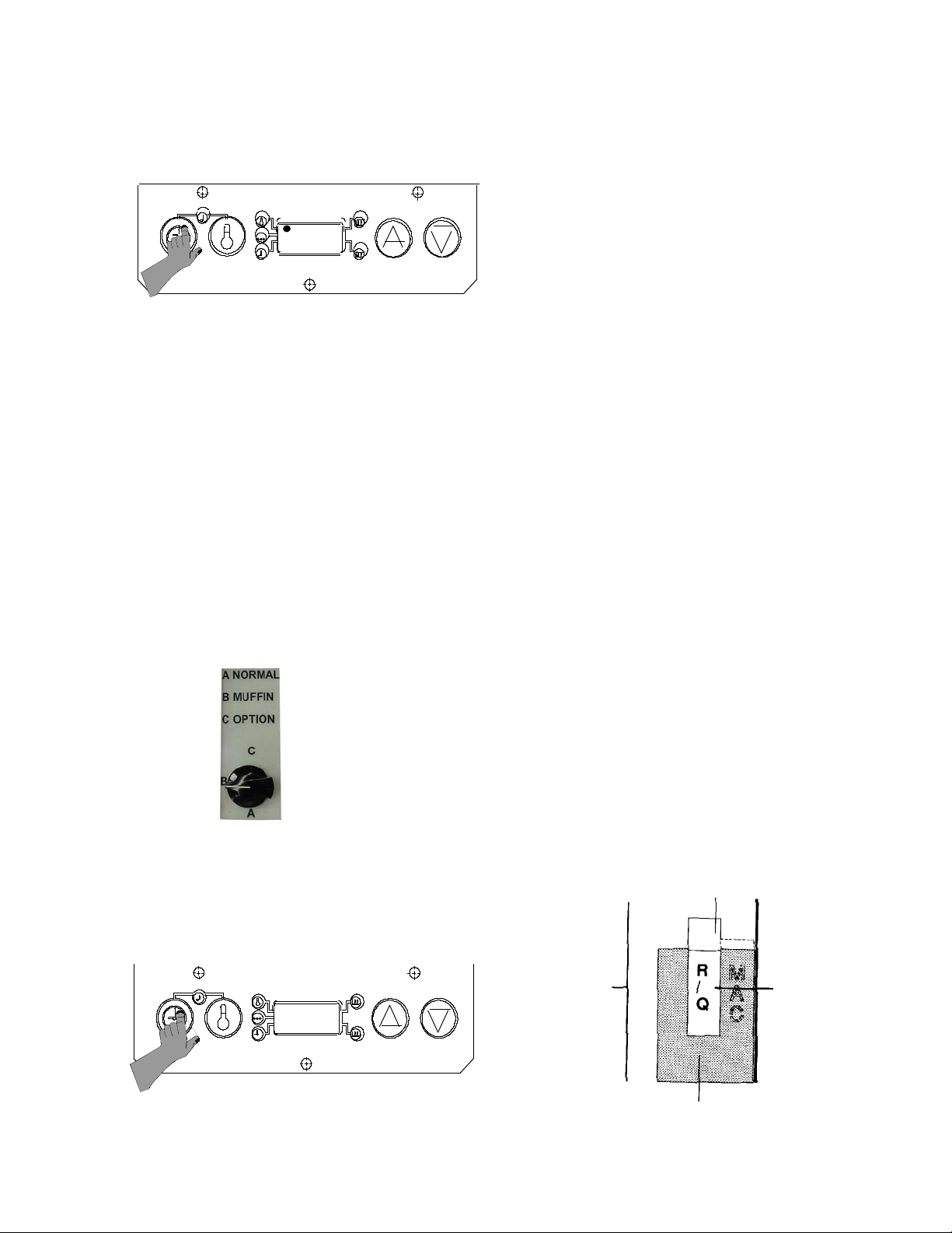
SETTING STOP BLOCKS
Stop blocks allow for proper crush when toasting
buns. The toaster leaves the factory with the stop
blocks set on R/Q.
Dual stop blocks allow you to switch back and forth
from Reg/Qtr. bun and Big Mac Bun toasting, or Rib
bun or Rye bun toasting.
1. Ensure the stop blocks are on the correct setting.
There are (6) combination Stop Block Settings:
1. R/Q / MAC 4. RIB / RYE
2. R/Q+ / MAC + 5. RIB+ / RYE +
3. R/Q- / MAC - 6. RIB- / RYE -
THE (+) SETTING IS FOR BUNS THAT ARE CUT
TOO THICK. THE (-) SETTING IS FOR BUNS CUT
TOO THIN. FOR NORMAL SIZE BUNS DO NOT
USE (+) or (-) SETTINGS.
[R/Q = REG/QTR]
2. Rotate stop blocks by hand to the desired
combination bun setting listed above.
3. View the stop block setting selected through the
index window bracket, which is located over the
figure 12
STOP BLOCK
INDEX WINDOW BRACKET
SIDE PANEL
BUN SETTING
(REGULAR BUNS)
2003 McDonald’s CorporationPart No. 411-553 Printed in the
All Rights Reserved United States of America
7
These times are preprogramed:
TIMER DESCRIPTION PRESET TIME
A Normal 35 sec.
B Muffin 70 sec.
C Option 105 sec.
To select a timer, turn the rotary switch to the
appropriate timer. The diplay will show the current
figure 10
2. To change programmed time, press and hold
the time button for 6 seconds. A beep will
sound and the time indicator light will flash.
Release the time button to show the current
toast time.
figure 11
The time indicator light will turn off, and the
display will change to show the actual
4. To cancel the time set function at any time,
press and release the temperature button.
time is reached, press and release the time
button to store the new time.
programmed time.
NOTE: The display reads in minutes and
seconds, so 105 seconds, displays as 1:45.
Repeat these steps for each timer.
platen temperature.
Page 8

left stop block. See figure 13
4. To switch between the two types of buns per
your stop block setting, locate the selector
lever on the front of the toaster frame. Move the
lever left or right to switch back and forth between
the combination setting. See figure 13.
BUN BOARD ADJUSTMENTS
1. Push or pull the bun board handle to desired
notched setting as indicated by graphics
stamped on top of bun board. See figure 13.
2. Bun board graphics are:
FRONT = REG, RYE, QTR HEELS
REAR = BIG MAC, (CROWNS) AND RIB
HEELS
CLEANING
1. Press the power switch to the off position.
2. Unplug toaster.
3. Allow toaster and platens to cool down.
4. Wipe entire platen with clean, damp grill cloth.
Full toaster cleaning must be done in the morning when toaster is cold. See your Planned
Maintenance Card for proper cleaning procedures.
IMPORTANT: Do not drape cord over hot toaster
bun board or platen. This will cause cord to burn.
PROBLEM CAUSE SOLUTION
Platen loose. Platen bolts loose. Tighten platen bolts.
Buns being crushed. Stop blocks not adjusted Adjust stop blocks.
properly.
Warped bun trays. Straighten or replace bun
trays.
Contact Bakery.
No Display. Fuse Defective. Check fuse with ohmmeter,
reading should be 1-2 ohms.
TROUBLESHOOTING GUIDE
figure 13
figure 13
FRONT OF
FRAME
SELECTOR
LEVER
2003 McDonald’s CorporationPart No. 411-553 Printed in the
All Rights Reserved United States of America
8
Page 9

WIRING DIAGRAM
Page 10

12
Les grille-pain Prince Castle à affichage numérique d état
solide sont pré-réglés en usine.
La température est pré-réglée et étalonné à 215°C.
Page 11

Page 12

1. Le grille-pain a trois minuteurs qui peut être
programmé de 5 à de 240 seconde.
Ces temps sont préprogrammés:
TIMER DESCRIPTION PRESET TIME
A Normal 0:35
B Muffin 1:10
C Option 1:45
Pour choisir un minuteur, tourner le
commutateur rotatif au minuteur correspondant.
L’exposition montrer le courant le temps
programmé
figure 10
2. Pour changer le temps programmé, appuyer et
tenir le bouton de temps pour de 6 seconde.
Une sonnerie semblera et l’indicateur de temps
clignotera. Relâcher le bouton de temps pour
montrer le temps de pain grillé actuel.
LA NOTE: L’exposition lit dans les minutes et
les secondes, donc les expositions de 105
seconde comme 1:45.
figure 11
1:45
3. Utiliser les en haut et boutons de flèche
descendante pour régler le temps de pain
grillé désiré. Quand le temps désiré est
attient, appuie et relâcher le bouton de temps
pour emmagasiner le nouveau temps.
Répéter ces étapes pour chaque minuteur.
4. Pour annuler la fonction de série de temps à
tout moment, appuyer et relâcher le bouton
de température. Le voyant de signalisation de
temps tournera de, et l’exposition changera
pour montrer la température de rouleau portepapiers véritable.
Page 13

Page 14

TS 016-i
Toasters
Precaution
During some checks, live electrical circuits will be exposed, and hot toasting
surfaces will be uncovered.
Hazard Communication Standard (HCS) – The procedures on this card
include the use of chemical products. These chemical products will be
highlighted with bold face letters followed by the abbreviation (HCS) in the
tools portion of the procedure. See the Hazard Communication Standard
(HCS) Manual for the appropriate Material Safety Data Sheet(s) (MSDS)
Applying Bun Toaster Release Agent
IMPORTANT: Use only McD Toaster Release Agent on bun toasters.
Other products may damage bun toasters.
1. Dust all loose crumbs from toaster surfaces.
2. Toaster platens must be well rinsed and dry. McD Bun Toaster Release Agent
may be applied to hot toaster platens. Before applying to hot platens, put on
protective gloves.
3. To coat top platen surface, thoroughly wet a clean, folded customer napkin or
paper towel, with Release Agent.
4. Rub a generous amount of Release Agent over entire surface of a platen until well
coated. Use protective gloves and No. 257 cleaning tool.
5. Repeat steps 2 and 3 for other platens, including undersides.
IMPORTANT: Platen undersides and difficult to reach areas can be coated
by placing a folded customer napkin or paper towel with Release Agent on
No. 257 cleaning tool to apply Release Agent to platen surface.
IMPORTANT: Do not wipe toaster with a damp cloth after Release Agent is
applied. This removes Release Agent and causes sticking.
6. If sticking occurs between weekly applications, reapply Release Agent using steps
1-4.
IMPORTANT: Toasterdoes not need to be recleaned or cooled down before
applying Release Agent.
IMPORTANT: Reapply Release Agent weekly, while toaster is cold between
monthly cleaning, to all platen surfaces.
Toasters
Prince Castle: Bun Toasters
Planned Maintenance
System: Maintenance
Requirement Card
(MRC)
Pictures and additional
information:
Corresponding Chapter of
Equipment Manual
When
Weekly
Tools
McD Bun Toaster Release
Agent (HCS), customer
paper napkins or paper
towels, protective gloves,
257 cleaning tool.
©2000 McDonald’s Corporation
Printed in DEC 00
Revised in SEP 00
Page 1 of 5
Page 15

Check Calibration of Temperature
IMPORTANT: Do not perform this procedure until the toaster has been on
for at least 45 minutes and temperature has stabilized. Do not use the toaster
during this 45-minute period.
1. Place the rear of the bun board on top of the control box and place the rest of the
bun board on top of the platen.
NOTE: On dual platen toasters (411 & 416), the bun board is only required
for use on the top platen.
2. On dual platen toasters, use to select the platen to be calibrated.
3. Center the digital thermometer on the front edge of the platen. When the
corresponding LED on the control panel turns on, immediately record the digital
thermometer temperature reading.
NOTE: On dual platen toasters (411 & 416), perform step 2 on the lower
platen first, then the upper platen.
IMPORTANT: If the temperature reading on the platen is greater than +/3°C (+/-5°F) compared to the toaster temperature display, proceed with step
3 to perform calibration. If temperature reading is within range, toaster is
functioning properly and does not require calibration.
4. Enter the calibration mode by pressing and holding for 6 seconds. A
beep will sound and the LED next to the calibration symbol will turn on. Release
all buttons.
5. Press and release to select upper platen for calibration or to select lower
platen. Allow 10 seconds for the display to stabililize. The display will show the
measured platen temperature value with no offset.
NOTE: On dual platen toasters (411 & 416), calibrate each platen separately.
6. When the corresponding platen LED turns on, use to adjust the display
temperature to match the reading recorded in step 3.
NOTE: Temperature can only be adjusted +/-5°C (+/-9°F).
7. Press to store the new calibrated temperature and to exit calibration mode.
IMPORTANT: After calibration is complete, allow one full heater on/off
cycle to allow the new calibrated temperature to stabilize.
TS 016-i
Toasters
When
Monthly
Tools
Digital thermometer with
surface probe.
©2000 McDonald’s Corporation
Printed in DEC 00
Revised in SEP 00
Page 2 of 5
Page 16

Clean Nickel Platen
PREPARING BUN TOASTER
1. If toaster is cool, heat to operating temperature.
IMPORTANT: Bun toaster must be at operating temperature for cleaning.
2. Turn toaster power switch to OFF position and unplug power cord.
CAUTION: Failure to unplug power cord before cleaning may cause
electrical shock.
3. Remove all buns, bun trays, and bun tray liners from the bun toaster stand.
4. Turn on the grill exhaust fan.
5. Move toaster stand in front of grill.
HOW TO CLEAN
1. Firmly attach McD No-Scratch Pad to cleaning tool. Use only nonabrasive blue
No-Scratch pads designed for grill cleaning. Do not use a green pad. It will
damage platen surface.
2. Pour one packet of McD Hi-Temp Grill Cleaner into a breakfast container base.
3. Put on protective gloves.
4. Turn bun board upside-down and lay on upper platen or plate.
5. Dip No-Scratch Pad into Hi-Temp Grill Cleaner.
6. Spread cleaner over bun board and lightly scrub until clean. Apply additional
cleaner as needed. Place bun board in the back sink area for cooling and rinsing.
7. If toaster is equipped with an aluminum plate, repeat step 6 so both sides of plate
are clean.
8. Dip No-Scratch Pad into cleaner and lightly spread a coasting of cleaner onto top
surface of platen.
IMPORTANT: Do not pour cleaner on surface. Apply only with No-Scratch
Pad and Cleaning Tool. Do not scrub while applying cleaner.
9. Repeat Step 8 for all platen surfaces, including undersides.
10. After repeating cleaner, lightly scrub all platen surfaces (including undersides)
with No-Scratch Pad until all soil liquifies. Apply additional cleaner to cleaning
as needed.
11. Remove No-Scratch Pad from cleaning tool. Fold a clean, damp grill cloth
lengthwise and lay it over the end of the cleaning tool. Thoroughly rinse platens,
including undersides, by wiping with a damp grill cloth. Before wiping platens,
always rinse grill cloth in clear water and wring it out until no soil is seen.
IMPORTANT: Thorough rinsing of the platen is required to ensure proper
release agent performance. Rinse platens with clean grill cloths until no soil
is seen on the cloth.
CAUTION: Do not pour water on platens or use dripping wet grill cloths.
TS 016-i Toasters
When
Monthly
Tools
McD Hi Temp Grill Cleaner
(HCS), McD Bun Toaster
Release Agent (HCS), McD
No Scratch Pad, base of
Big Breakfast container,
No. 257 cleaning tool,
clean grill cloths (qty. 6-8),
customer paper napkins or
paper towels, protective
gloves.
©2000 McDonald’s Corporation
Printed in DEC 00
Revised in SEP 00
Page 3 of 5
Page 17

©2000 McDonald’s Corporation
Printed in DEC 00
Revised in SEP 00
Page 4 of 5
TS 016-i
Toasters
12. Repeat the rinsing procedure in Step 11 with a fresh, clean, damp grill cloth to
ensure all cleaner and soil are removed from platens.
13. Wipe remaining parts of the toaster with a clean damp cloth.
14. Take bun tray platform, bun board, and aluminum plate to back sink. Scrub with
a pot brush or No-Scratch Pad in a solution of McD All Purpose Concentrate.
Do not use abrasive pads. Rinse parts under running water and let air dry.
Tighten Platen and Leg Bolts
TIGHTEN PLATEN BOLTS
1. Turn the power switch to the OFF Position.
2. Unplug the power cord.
3. Allow toaster to cool before proceeding.
4. Using an adjustable wrench, tighten the platen bolts which hold handle in upright
position.
TIGHTEN LEG BOLTS
1. Carefully turn the toaster upside down for access to legs.
2. Adjust and tighten leg bolts to obtain a level setting for toasting.
3. Set toaster right side up and check for level setting.
4. Adjust leg bolts as necessary until toaster sits level.
5. Plug the power cord into the appropriate electrical receptacle.
6. If the toaster is about to be used, turn the power switch to ON position.
When
Monthly
Tools
Adjustable wrench,
flatblade screwdriver
Page 18

©2000 McDonald’s Corporation
Printed in DEC 00
Revised in SEP 00
Page 5 of 5
TS 016-i
Toasters
When
Monthly
Tools
Pliers, hammer, file
Check Bun Tray Platforms, Bun Board, Bun Trays and Spatulas
IMPORTANT: This check procedure should be conducted while the
platforms, trays and spatulas are cold. It should be done for all spatulas,
trays and platforms.
BUN SPATULA
1. Lay the spatula on a flat work table top.
2. Make sure the entire surface is flat, including the front edge. The front end of
bun spatula must be free from necks and burrs.
3. Sharpen front edge of spatula so all nicks and burrs are removed.
IMPORTANT: Straightening curled corners with pliers and hammer middle
part of the tray flat.
BUN TRAY
1. Lay the track on a flat work tabletop and inspect for flatness.
2. Inspect the try for uniform height.
3. Straightened curled corners with pliers and hammer middle part of the tray flat.
BUN TRAY PLATFORM
1. Remove the platform from the lower part of the toaster.
2. Lay the platform on a flat work tabletop and inspect the entire surface to make
sure it is flat.
3. Using pliers or a hammer, straighten as needed.
4. Reinstall the platform into toaster.
BUN BOARD
1. Remove the bun board from toaster.
2. Lay the bun board on a flat work tabletop and inspect for flatness.
3. Measure the distance between the tabletop and the bottom side of the bun board in
the front, center, and rear. It should be approximately 1/2" (13mm) for all
toasters except Big Mac 412 and 416 series, and approximately 1/2" (19cm) for
Big Mac Toasters.
4. Bend as needed to maintain flatness.
Page 19

©2000 McDonald’s Corporation
Printed in DEC 00
Revised in SEP 00
Page 1 of 5
TS 016-i
Grille-pains
Images et informations
additionnelles:
Chapitre correspondant du
manuel d’équipement
Quand
Hebdomadairement
Outils
Agent de démoulage de
grille-petits pains McD
(HSC), serviettes de table
en papier ou essuie-tout
du client, gants
protecteurs, outil de
nettoyage no 257.
Grille-pains
Prince Castle: Grille-petits pains
Précaution
Durant certaines vérifications, les circuits électriques sous tension seront
exposés et les surfaces de grillage chaudes seront découvertes.
Hazard Communication Standard (HCS)- Les procédures sur cette carte
incluent l’utilisation de produits chimiques. Ces produits chimiques seront mis
en surbrillance avec des lettres en gras suivies de l’abréviation (HSC) dans la
partie outils de la procédure. Voir le manuel Hazard Communication Standard
(HSC) pour voir la ou les feuille(s) des Données de sécurité du matériel (FDSM).
Application de l’agent de démoulage de grille-petits pains
IMPORTANT: Utilisez seulement l’agent de démoulage grille-petits pains
McD sur les grilles-petits pains. D’autres produits pourraient endommager
le grille-petits pains.
1. Enlevez toutes les miettes des surfaces du grille-pain.
2. Les plaques du grille-pain doivent être bien rincées et séchées. L’agent de
démoulage de grille-petits pains McD peut être appliqué sur les plaques chaudes
du grille-pain. Mettez les gants protecteurs avant d’appliquer sur les plaques chaudes.
3. Pour couvrir la surface supérieure de la plaque, mouillez à fond une serviette de
table pliée ou un essuie-tout de client avec l’agent de démoulage.
4. Frottez une quantité généreuse de l’agent de démoulage sur toute la surface de la
plaque jusqu’à ce qu’elle soit bien recouverte. Utilisez les gants protecteurs et
l’outil de nettoyage no 257.
5. Répétez les étapes 2 et 3 pour d’autres plaques y compris les dessous.
IMPORTANT: Les dessous des plaques et les endroits difficiles à atteindre
peuvent être couverts en plaçant une serviette de table en papier du client ou
un essuie-tout avec l’agent de démoulage sur l’outil de nettoyage no 257 pour
appliquer l’agent de démoulage à la surface de la plaque.
IMPORTANT: Ne pas essuyer le grille-pain avec un linge humide après avoir
appliqué l’agent de démoulage. Cela enlève l’agent de démoulage et colle.
6. Si la surface colle entre les applications hebdomadaires, réappliquer l’agent de
démoulage en vous basant sur les étapes 1 à 4.
IMPORTANT: Le grille-pain n’a pas besoin d’être relavé ou refroidi avant
d’appliquer l’agent de démoulage.
IMPORTANT: Réappliquer l’agent de démoulage à toutes les surfaces de la
plaque à chaque semaine quand le grille-pain est froid entre les nettoyages
mensuels.
Système d’entretien
planifié: carte de
spécifications de
maintenance (CSM)
Page 20

©2000 McDonald’s Corporation
Printed in DEC 00
Revised in SEP 00
Page 2 of 5
TS 016-i
Grille-pains
Vérifiez l’étalonnage de la température
IMPORTANT: Ne pas exécuter cette procédure avant que le grille-pain n’ait
été en marche pendant 45 minutes et que la température se soit stabilisée. Ne
pas utiliser le grille-pain pendant cette période de 4 minutes.
1. Placez l’arrière de la planche à petits pains par-dessus la boîte de commande et
placez le reste de la planche à petits pains par-dessus la plaque.
NOTE: Sur les grille-pain à plaque double (411 et 416), la plaque de petits
pains est seulement nécessaire pour être utilisée sur la plaque supérieure.
2. Sur les grille-pain à plaque double, utilisez pour sélectionner la plaque à
étalonner.
3. Centrez le thermomètre digital en face de la plaque. Lorsque le voyant
correspondant s’allume sur le panneau de commande, enregistrez immédiatement
la lecture de la température du thermomètre digital.
NOTE: Sur les grille-pain à plaque double (411 et 416), exécutez d’abord
l’étape 2 sur la plaque la plus basse puis ensuite sur la plaque du haut.
IMPORTANT: Si la lecture de la température sur la plaque est plus élevée
que +/- 3°C (+/-5°F) comparativement à l’affichage de la température du
grille-pain, exécutez l’étape 3 pour faire l’étalonnage. Si la lecture de la
température est en dedans de l’intervalle, le grille-pain fonctionne
adéquatement et n’a pas besoin d’étalonnage.
4. Introduisez le mode d’étalonnage en appuyant et en maintenant pour 6
secondes. Un bip retentira et le voyant situé à côté du symbole d’étalonnage
s’allumera. Relâchez tous les boutons.
5. Appuyez sur pour sélectionner la plaque supérieure pour l’étalonnage ou
sur t pour sélectionner la plaque inférieure. Laissez 10 secondes pour que
l’affichage se stabilise. L’affichage va montrer la valeur mesurée de la
température de la plaque sans décalage.
NOTE: Sur les grille-pain à plaque double (411 et 416), étalonnez chaque
plaque séparément.
6. Lorsque le voyant correspondant de la plaque s’allume, utilisez pour
ajuster l’affichage de la température pour qu’elle corresponde à la lecture
enregistrée à l’étape 3.
NOTE: La température peut seulement être ajustée +/-5°C (+/-9°F).
7. Appuyez sur pour mémoriser la nouvelle température étalonnée et quitter le
mode d’étalonnage.
IMPORTANT: Lorsque l’étalonnage est terminé, laissez un cycle complet
marche/arrêt de la plaque chauffante pour permettre à la nouvelle
température étalonnée de se stabiliser.
Quand
Tous les mois
Outils
Thermomètre digital
avec sonde en
surface.
Page 21

©2000 McDonald’s Corporation
Printed in DEC 00
Revised in SEP 00
Page 3 of 5
TS 016-i
Grille-pains
Nettoyage de la plaque en nickel
PRÉPARATION DU GRILLE-PETITS PAINS
1. Si le grille-pain est froid, réchauffez-le jusqu’à la température de fonctionnement.
IMPORTANT: le grille-petits pain doit être à la température de
fonctionnement pour le nettoyage.
2. Mettez l’interrupteur d’alimentation du grille-pain en position OFF (ARRÊT) et
débranchez le cordon d’alimentation.
MISE EN GARDE: En omettant de débrancher le cordon d’alimentation
avant le nettoyage, on peut causer un choc électrique.
3. Retirez tous les petits pains, plateaux à petits pains et les garnitures de plateau à
petits pains du support de grille-petits pains.
4. Mettez en marche le ventilateur aspirant du gril.
5. Déplacez le support de grille-pain pour le mettre en face du gril.
COMMENT NETTOYER
1. Attachez fermement le tampon No-Scratch (ne grattant pas) McD à l’outil de nettoyage.
N’utilisez que des tampons bleus non abrasifs No-Scratch conçus pour le nettoyage
de gril. N’utilisez pas un tampon vert. Il endommagerait la surface de la plaque.
2. Versez un paquet de produit de nettoyage de gril température élevée McD dans
une base de récipient de petit déjeuner.
3. Mettez les gants protecteurs.
4. Retournez la planche à petits pains et posez-la sur la plaque supérieure.
5. Trempez le tampon No-Scratch dans un produit de nettoyage de gril température élevée.
6. Étalez le produit de nettoyage sur la planche à petits pains et brossez-la un peu
jusqu’à ce qu’elle soit propre. Appliquez un supplément de produit de nettoyage si
nécessaire. Placez la planche à petits pains dans la zone arrière de l’évier pour
refroidissement et rinçage.
7. Si le grille-pain est muni d’une plaque en aluminium, répétez l’étape 6 de sorte
que les deux côtés de la plaque soient propres.
8. Trempez le tampon No-Scratch dans un produit de nettoyage et étalez légèrement
une couche de produit de nettoyage sur la surface supérieure de la plaque.
IMPORTANT: Ne versez pas le produit de nettoyage sur la surface. Ne
l’appliquez qu’avec le tampon No-Scratch et l’outil de nettoyage. Ne brossez
pas tout en appliquant le produit de nettoyage.
9. Répétez l’étape 8 pour toutes les surfaces de plaque y compris les dessous.
10. Après avoir répété l’application du produit de nettoyage, brossez un peu toutes les
surfaces de plaque (y compris les dessous) avec le tampon No-Scratch jusqu’à ce
que toute la salissure soit liquéfiée. Appliquez un supplément de produit de
nettoyage si nécessaire.
11. Retirez le tampon No-Scratch de l’outil de nettoyage. Pliez un chiffon propre et
humide pour gril dans le sens de la longueur et posez-le sur l’extrémité de l’outil
de nettoyage. Rincez complètement les plaques, y compris leurs dessous en les
essuyant avec un chiffon humide pour gril. Avant d’essuyer les plaques, rincez
toujours le chiffon pour gril dans l’eau claire et faites sortir l’eau jusqu’à ce
qu’aucune trace de salissure ne soit vue.
IMPORTANT: Un rinçage complet de la plaque est requis pour assurer un fonctionnement correct de l’agent de démoulage. Rincez les plaques avec des chiffons
propres pour gril jusqu’à ce qu’aucune trace de salissure ne soit vue surle chiffon.
MISE EN GARDE: Ne versez pas d’eau sur les plaques et n’utilisez pas de
chiffons pour gril humides et dégouttant.
Quand
À tous les mois
Outils
Produit de nettoyage de
gril température élevée
McD (HCS), agent de
démoulage de grille-petits
pains McD (HCS),
tampon No-Scratch (ne
grattant pas) McD, base
de récipient Big Breakfast
(gros déjeuner), outil de
nettoyage no 257,
chiffons de nettoyage de
gril (quantité 6-8),
serviettes de table en
papier ou essuie-tout du
client, gants protecteurs.
Page 22

©2000 McDonald’s Corporation
Printed in DEC 00
Revised in SEP 00
Page 4 of 5
TS 016-i
Grille-pains
12. Répétez la procédure de rinçage de l’étape 11 avec un nouveau chiffon pour gril,
propre et humide, pour assurer que tout le produit de nettoyage et toute la
salissure soient enlevés des plaques.
13. Essuyez les pièces restantes du grille-pain avec un chiffon humide et propre.
14. Mettez la plate-forme de plateau à petits pains, la planche à petits pains et la
plaque d’aluminium dans l’évier arrière. Brossez-les avec une brosse de pot ou
un tampon No-Scratch dans une solution de concentré McD à tout faire.
N’utilisez pas des tampons abrasifs. Rincez les pièces dans de l’eau courante et
laissez-les sécher à l’air.
Resserrer les boulons de la plaque et des pattes
RESERRER LES BOULONS DE LA PLAQUE
1. Mettez l’interrupteur d’alimentation à la position ARRÊT (OFF).
2. Débranchez le cordon d’alimentation.
3. Laissez le temps au grille-pain de refroidir avant de procéder.
4. En utilisant une clé à vis ajustable, resserrez les boulons de la plaque qui tiennent
la poignée en position verticale.
RESSERRER LES BOULONS DES PATTES
1. Tournez le grille-pain à l’envers avec soin pour accéder aux pattes.
2. Ajustez et resserrez les boulons des pattes pour obtenir un niveau de réglage pour
le brunissement.
3. Réglez le grille-pain, le côté droit en haut, et vérifiez le niveau de réglage.
4. Ajustez les boulons de pattes comme nécessaire jusqu’à ce que le grille-pain soit à
niveau.
5. Branchez le cordon d’alimentation dans la prise de courant appropriée.
6. Si le grille-pain est sur le point d’être utilisé, mettez l’interrupteur d’alimentation
à la position MARCHE (ON).
Quand
À tous les mois
Outils
Clé à vis ajustable,
tournevis à lame plate
Page 23

©2000 McDonald’s Corporation
Printed in DEC 00
Revised in SEP 00
Page 5 of 5
TS 016-i
Grille-pains
Vérifiez les plates-formes pour plateaux à petits pains, les
planches à petits pains, les plateaux à petits pains et les spatules
IMPORTANT: Cette procédure de vérification devrait être faite lorsque les
plates-formes pour plateaux et les spatules sont froides. Ceci devrait être fait
pour toutes les spatules, plateaux et plates-formes.
SPATULE POUR PETIT PAIN
1. Déposez la spatule sur un dessus de table de travail plat.
2. Assurez-vous que toute la surface est plate y compris le rebord avant. Le rebord
arrière de la spatule pour petit pain ne doit pas avoir d’entailles ni de bavures.
3. Aiguisez le rebord avant de la spatule pour enlever les entailles et bavures.
IMPORTANT: Redresser les coins retroussés avec des pinces et un marteau
PLATEAU À PETIT PAIN
1. Déposez le rail sur un dessus de table de travail plat et inspectez la planitude.
2. Inspectez le plateau pour voir si sa grandeur est uniforme.
3. Redressez les coins retroussés dans la partie plate du milieu du plateau avec des
pinces et un marteau.
PLATE-FORMES POUR PLATEAUX À PETITS PAINS
1. Enlevez la plate-forme de la partie inférieure du grille-pain.
2. Déposez la plate-forme sur un dessus de table de travail plat et inspectez toute la
surface pour être sûr qu’elle est plate.
3. Redressez au besoin avec des pinces et un marteau.
4. Réinstallez la plate-forme dans le grille-pain.
PLANCHE À PETITS PAINS
1. Enlevez le petit pain du grille-pain.
2. Déposez la planche à petits pains sur un dessus de table de travail plat et inspectez
pour être sûr qu’elle est plate.
3. Mesurez la distance devant, au centre et en arrière entre le dessus de la table et le
côté bas de la planche à petits pains. Cela devrait être approximativement 13 mm
pour tous les grille-pain sauf pour les séries Big Mac 412 et 416 et
approximativement 19 cm pour les Big Mac Toasters.
4. Pliez selon les besoins pour garder plat.
Quand
À tous les mois
Outils
Pinces, marteau, lime
 Loading...