

Page 1
SOLID STATE DIGITAL ENERGY SAVING TOASTER
PRINCE CASTLE MODEL NO. 411-SD SERIES
This equipment chapter is to be placed in the
toasters section of your Equipment Manual.
MANUFACTURED FOR
MCDONALD’S®
BY
PRINCE CASTLE INC.
355 KEHOE BLVD.
CAROL STREAM, IL. 60188 USA
PHONE 1-630-462-8800
TOLL FREE NUMBER
1-800-323-2930
FAX:1-630-462-1460
WARRANTY .............................................................................................................................................................................................. Page 1
SIDE VIEW ................................................................................................................................................................................................ Page 2
FRONT VIEW............................................................................................................................................................................................ Page 3
REAR VIEW .............................................................................................................................................................................................. Page 3
INTERNAL VIEW ..................................................................................................................................................................................... Page 4
EQUIPMENT SET-UP.............................................................................................................................................................................. Page 5
PROGRAMMING ...................................................................................................................................................................................... Page 6
CLEANING ................................................................................................................................................................................................ Page 8
TROUBLESHOOTING ............................................................................................................................................................................. Page 8
DI AGNOSTIC TROUBLESHOOTING ....................................................................................................................................................... Page 9-11
TRANSLATIONS (FRENCH, GERMAN, SPANISH, ITALIAN) ......................................................................................................... Page 12-39
WIRING DIAGRAM .................................................................................................................................................................................. Page 40
LIMITED WARRANTY
This product is warranted to be free from defects in material and/or workmanship for a period of (2) years
from date of original installation not to exceed 30 months from date of shipment from our factory. Printed
circuit boards and platen are warranted for a period of (3) years from date of original installation not to
exceed 42 months from date of shipment from our factory. Any part or component which proves to be
faulty in material and/or workmanship within the warranty period will be replaced or repaired without cost
to the customer for parts or labor. (At the option of Prince Castle, Inc.)
This warranty is subject to the following exceptions/conditions:
Any use of Non-genuine Prince Castle spare parts voids this warranty, and all work must be per-
formed by an authorized Prince Castle Service Agent.
All labor should be performed during regular working hours. Overtime premium will not be covered.
Travel charges are limited to 100 miles (200 km) round trip, 2 hours travel time, one trip per repair.
Damage caused by carelessness, neglect, and/or abuse (e.g., using wrong current, dropping, tam-
pering with or altering electrical components, or improper cleaning) is not covered.
Equipment damaged in shipment, by fire, flood or an act of God.
This manual is for the exclusive use of licensees and employees of McDonald’s Systems, Inc.
2002 McDonald’s Corporation Printed in the
All Rights Reserved United States of America
Part No. 411-543 Rev. C
Page 2
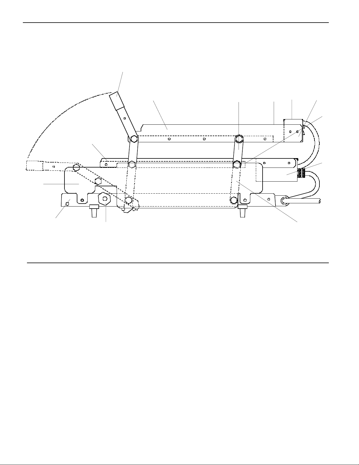
SIDE VIEW
12
1
23456
7
13
8
11
PARTS LIST
10
ITEM PART NUMBER DESCRIPTION
1 411-149S Handle and Lever Assy.
2 411-441 Right Hand Upper Bun Fence
411-440 Left Hand Upper Bun Fence
3 411-461S Upper Rear Lever Assy.
4 411-378 Upper Rear Bun Fence
5 411-31 Upper Cover
6 411-283 Upper Chassis
7 411-381 Lower Rear Bun Fence
8 411-741 Lower Chassis
9 411-459S Lower Rear Lever Assy.
10 411-137 Right Hand Stop Block
411-138 Left Hand Stop Block
11 411-2S Base
12 411-444 Side Panel, Right Hand
411-445 Side Panel, Left Hand
13 411-379 Right Hand Lower Bun Fence
411-380 Left Hand Lower Bun Fence
Not Shown 411-114 Safety Latch
Not Shown 411-744 Bun Board
9
2000 McDonald’s Corporation Part No. 411-543 Rev C Printed in the
All Rights Reserved United States of America
2
Page 3
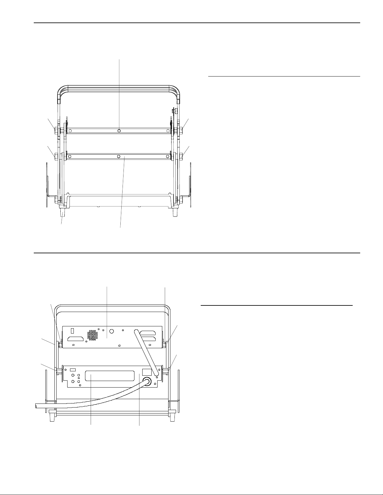
FRONT VIEW
1
PARTS LIST
2
3
5
REAR VIEW
2
3
4
1
2
ITEM PART NUMBER DESCRIPTION
1 411-483S Upper Platen 230V
411-6S Upper Platen 120V
2 411-60 Front Upper
Platen Stud
3 411-60 Front Lower
Platen Stud
4 411-486S Lower Platen 230V
411-8S Lower Platen 120V
5 89-959S Foot (Pkg. of 4)
2
PARTS LIST
3
3
4
4
6
2000 McDonald’s Corporation Part No. 411-543 Rev C. Printed in the
All Rights Reserved United States of America
5
ITEM PART NUMBER DESCRIPTION
1 411-712 Upper Faceplate
2 411-57 Platen Spacer
3 411-147 Rear Upper
Platen Stud
4 411-61 Rear Lower
Platen Stud
5 411-705 Lower Faceplate
6 411-707 Overlay
3
Page 4
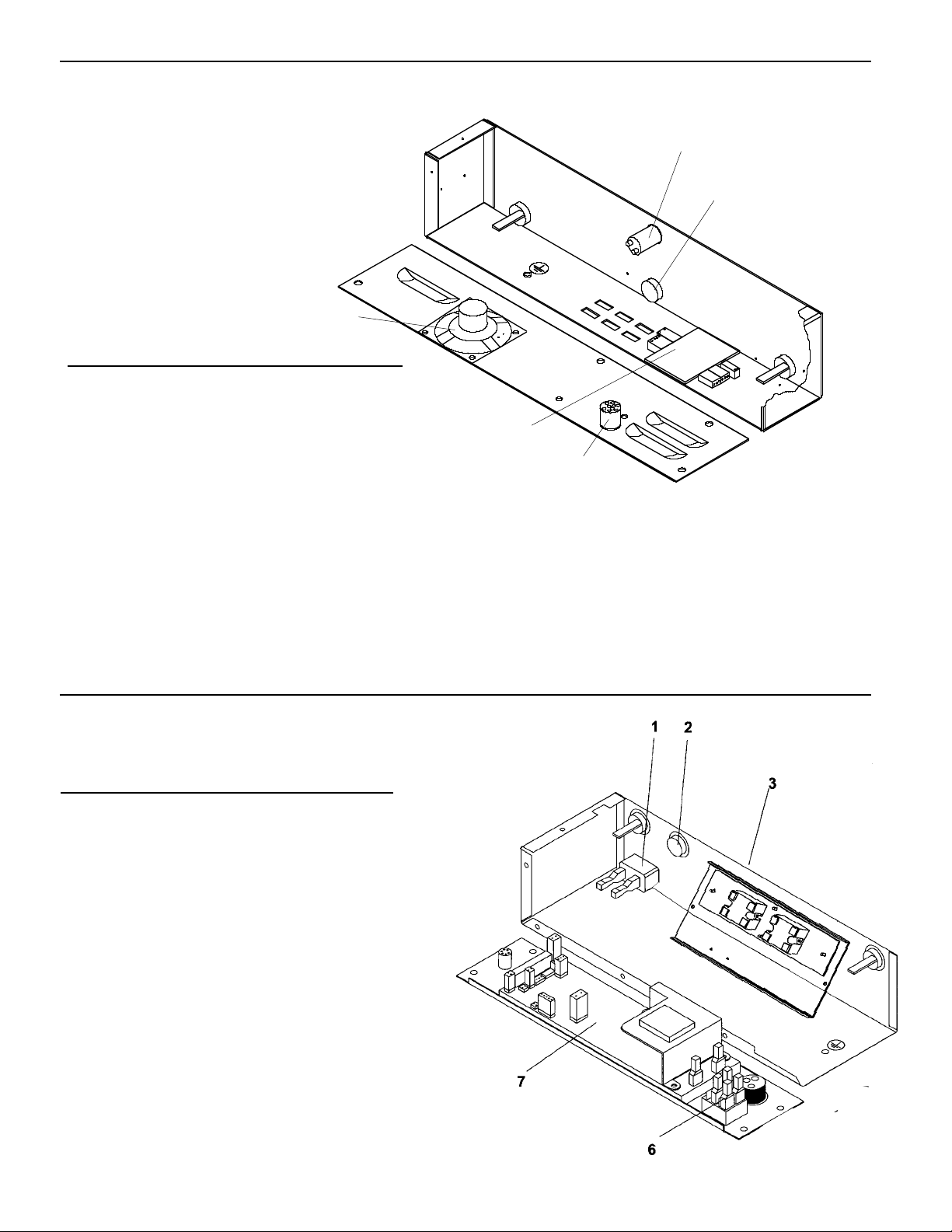
INTERNAL VIEW UPPER CONTROL BOX
5
PARTS LIST
1
2
ITEM PART NUMBER DESCRIPTION
1 213-257S Bun Done Light
2 411-700S Upper Probe
3 411-740 Interconnect Cable
4 411-14S Interconnect Board
5 213-229S Speaker
INTERNAL VIEW LOWER CONTROL BOX
PARTS LIST
ITEM PART NUMBER DESCRIPTION
4
3
1 65-058S Relay, Lower & Upper
2 411-700S Probe
3 72-301S Power Cord 220-230V
72-274 Power Cord 120V
4 78-166S Rocker Switch
5 411-427-05S Control PCB 220-230V
411-601S Control PCB 120V
2000 McDonald’s Corporation Part No. 411-543 Rev C
All Rights Reserved
4
United States of America
Printed in the
Page 5
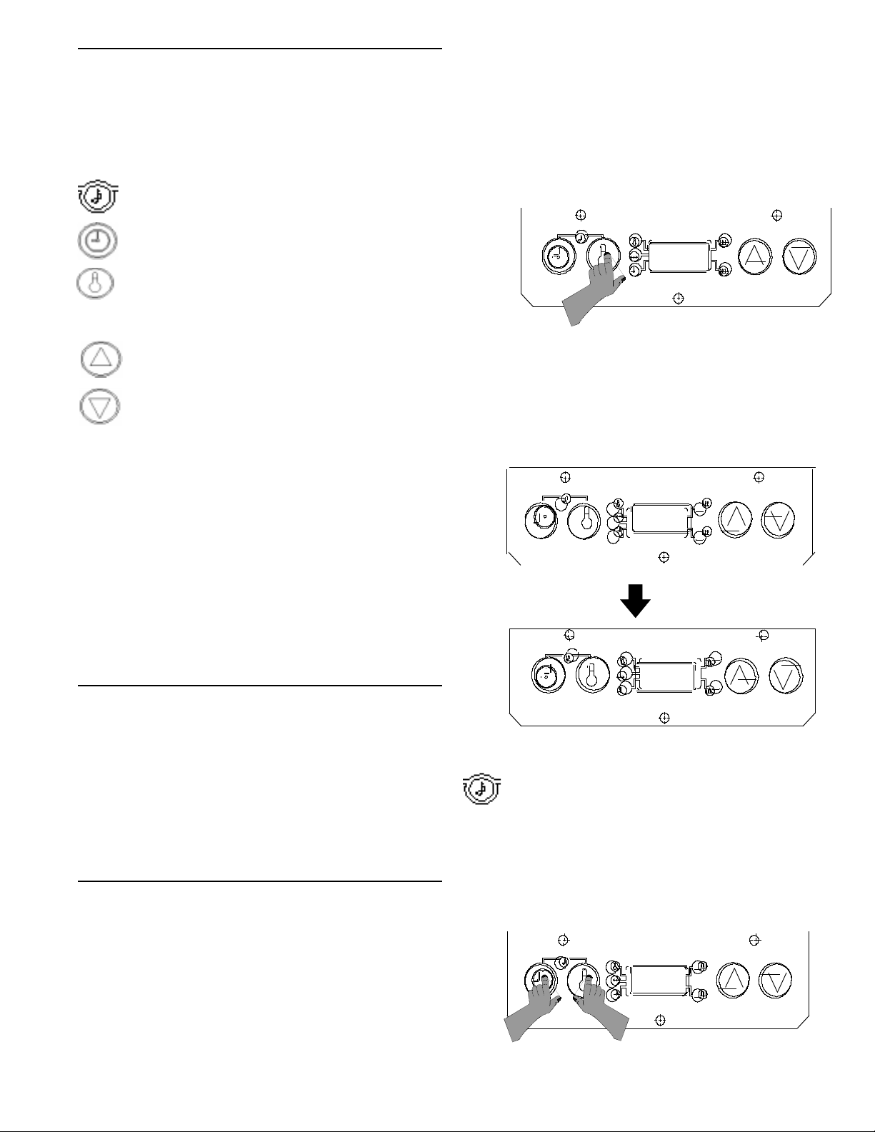
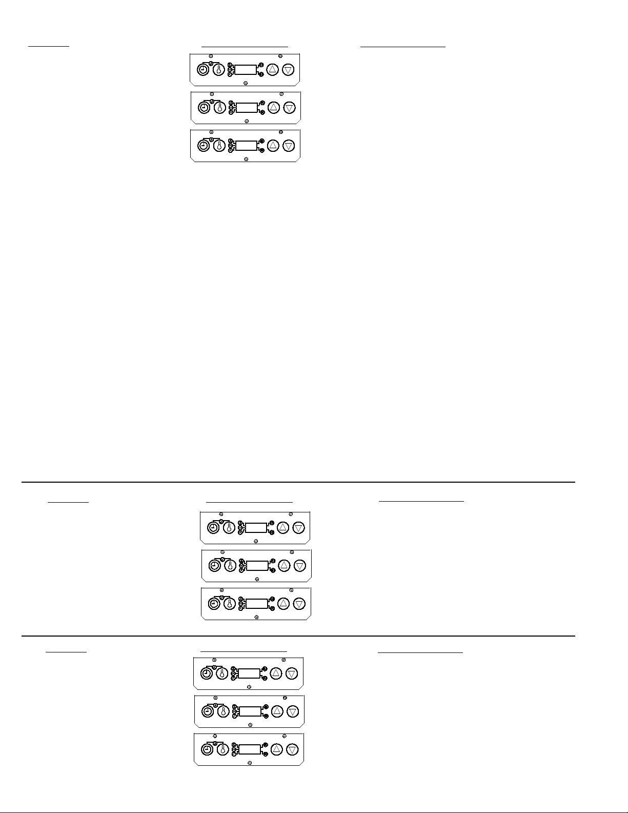
SYMBOLS & TERMS
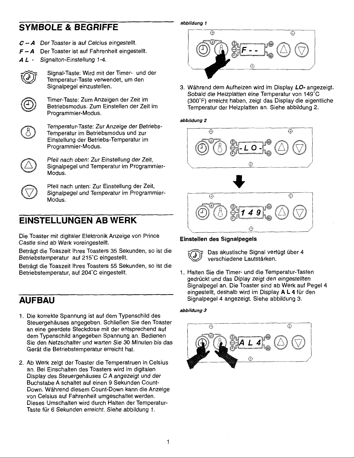
C - - A Toaster is set on Celsius.
F - - A Toaster is set on Fahrenheit.
A L - Alarm Level setting 1-4.
operating temperature.
2. The toaster is factory-set to display temperatures
reading in Celsius. When the toaster is turned on,
the digital display on the control box will read C--A
for Celsius, and the “A” will begin to count down 9
seconds. During this countdown, you can change
the temperature display from Celsius to Fahrenheit
Sound Button: Used with timer button
and temperature button to set alarm
level.
Timer Button: Used to view time in run
mode. Used to set time in program mode.
Temperature Button: Used to view set
point temperature in run mode, and used
to set the set point temperature in
program mode.
Up Arrow: Used to set time, sound and
temperature in program mode.
Down Arrow: Used to set time, sound,
and temperature in program mode.
ENERGY SAVING MODE
To conserve energy during non-toasting periods,
pull the toaster handle down, so that the timing
cycle activates. When the audio alarm goes off,
indicating that the toasting time is complete, DO
NOT pull the handle up. Allow the audio alarm to
sound until the alarm shuts off, the display will
alternately flash “Stand” and “By”, indicating the
toaster is in the energy savings mode. The toaster
platens will continue to maintain the programmed
operating temperature, raising the toaster handle
will put the toaster back into the operation mode.
figure 1
F - -
readings. To change temperature display, press
and hold the temperature button for six seconds.
See figure 1.
3. During the pre-heat cycle, the display will read -
L O -. When the platen temperature reaches
figure 2
- L O -
1 4 9
FACTORY PRE-SET
Prince Castle’s Solid State Digital Display toasters are
pre-set at the factory.
If your toaster model is set for a 35 second toast time,
then the temperature is pre-set and calibrated to
215°C.
If your toaster model is set for a 55 second toast time,
then the temperature is pre-set and calibrated to
204°C.
SET-UP
1. Refer to the nameplate on the control box for the
proper operating voltage. Connect the toaster to a
grounded receptacle that matches the nameplate
voltage information. Press the power switch to the
on position, allow the unit 30 minutes to reach
2000 McDonald’s Corporation Part No. 411-543 Rev C Printed in the
All Rights Reserved United States of America
149°C (300° F), the display will begin to show
the actual platen temperatures throughout
the toasting cycles. See figure 2
Sound Level Adjustment
The audio alarm has four sound levels.
1. Press and hold the time button and temperature
buttons simultaneously. The display will show the
current sound level. The toasters are factory set at
level 4, and the display will read, A L 4 for Alarm
figure 3
A L 4
5
Page 6
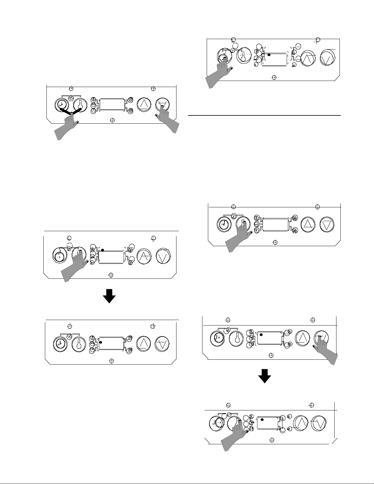
Level 4. See figure 3.
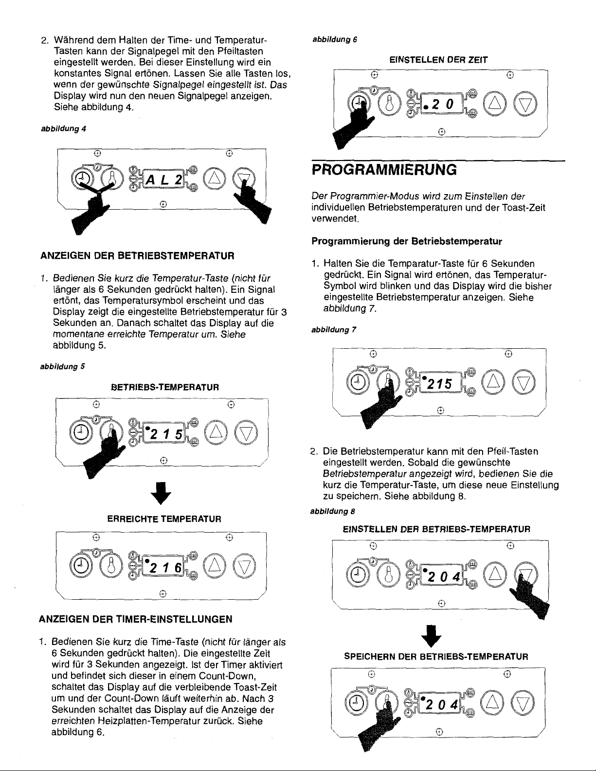
2. While holding the time and temperature buttons,
press the up or down arrow buttons to adjust
the sound level. A continuous tone will sound.
Release all buttons when the desired sound
figure 4
figure 6
SET TIME
2 0
A L 2
level is reached. The display will show the
current sound level. See figure 4.
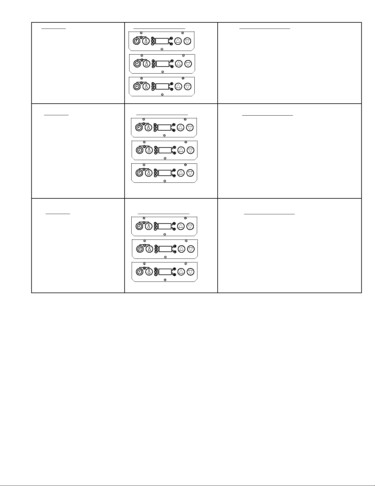
VIEW SET POINT TEMPERATURE
1. Press and release the temperature button. (Do not
hold for more than 6 seconds.) A beep will sound,
the temperature indicator will turn on, and the
display will show the set point temperature for
three seconds. The display will then change to
show the actual temperature. See figure 5.
figure 5
SET POINT TEMPERATURE
2 1 5
change to show actual platen temperature. See
figure 6.
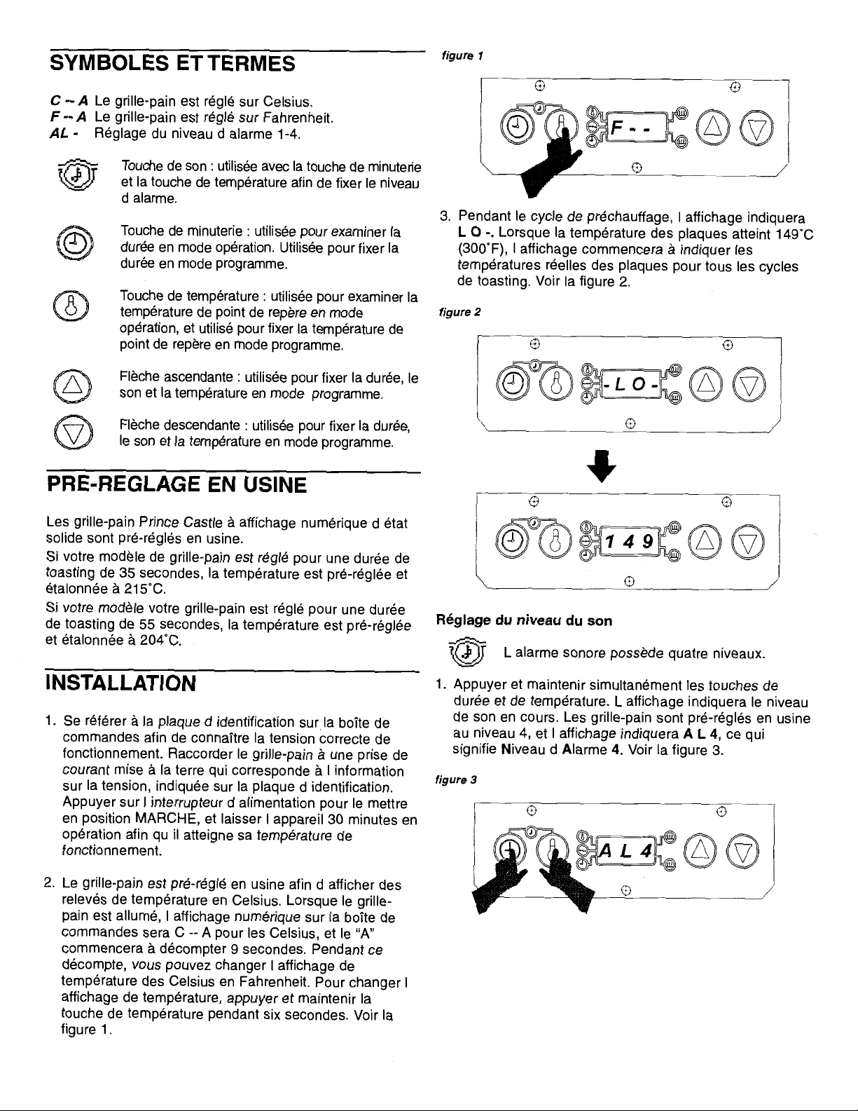
PROGRAMMING
The programming modes are used for setting individual set point temperature, and setting toast times.
Programming the Set Point Temperature
1. Press and hold the temperature button for six
seconds. A beep will sound, the temperature
indicator light will blink, and the display will show
215
figure 7
the current set point temperature. See figure 7.
2. To change the set point temperature, use the up
or down arrow. Once the desired temperature is
figure 8
ACTUAL TEMPERATURE
ADJUST SET POINT TEMPERATURE
2 0 4
2 1 6
VIEW TIMER SETTING
1. Press and release the time button. (Do not
press the time button for more than 6 seconds.)
The set time will be displayed for three seconds. If the timer is activated and is in a countdown sequence, the time remaining will be
displayed, and will continue to countdown to
zero. After three seconds, the display will
2000 McDonald’s Corporation Part No. 411-543 Rev C Printed in the
All Rights Reserved United States of America
6
STORE SET POINT TEMPERATURE
2 0 4
Page 7
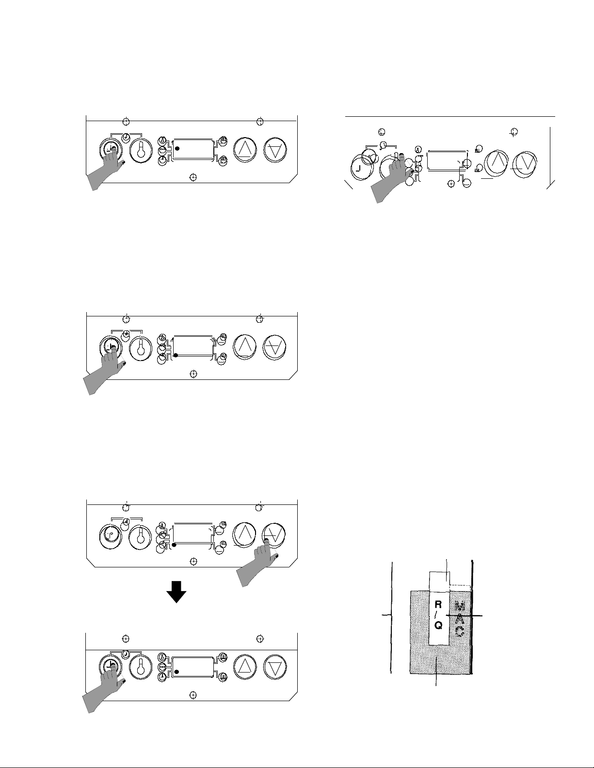
displayed, press the temperature button to store
the new setting. See figure 8.
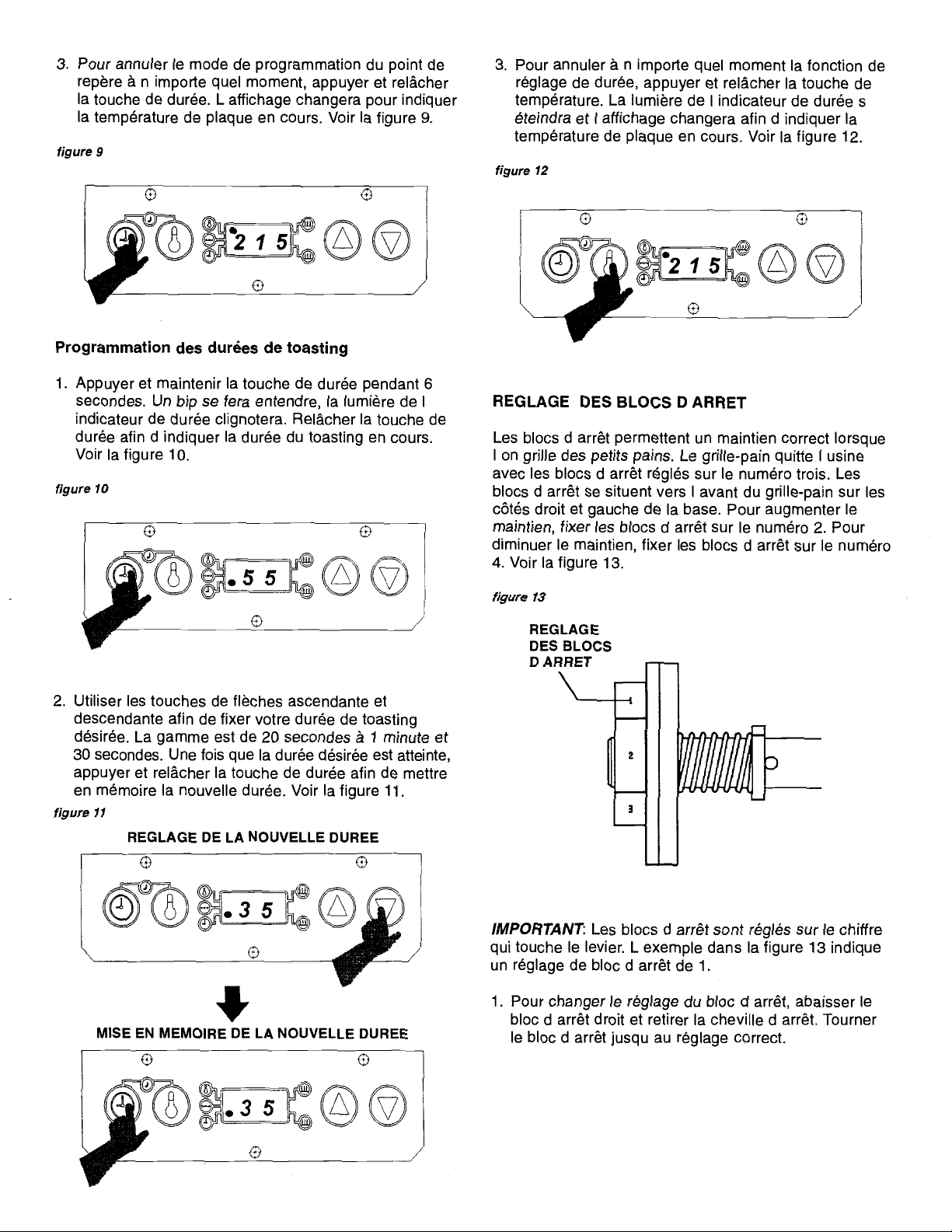
3. To cancel the set point programming mode at any
time, press and release the time button. The
figure 9
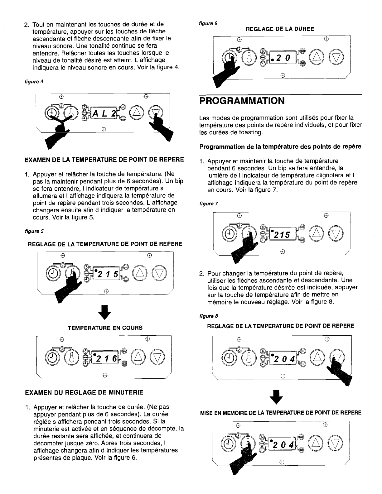
time is reached, press and release the time
button to store the new time. See figure 11.
3. To cancel the time set function at any time, press
and release the temperature button. The time indicator light will turn off, and the display will change to
figure 12
2 1 5
display will change to show the actual platen
temperature. See figure 9.
Programming Toast Times
1. Press and hold the time button for 6 seconds. A
beep will sound, and the time indicator light will
figure 10
5 5
blink. Release the time button to show the
current toast time. See figure 10.
2. Use the up and down arrow buttons to set your
desired toast time. The range is from 20 seconds to 1 minute, 30 seconds. When desired
figure 11
SETTING THE NEW TIME
2 1 5
show the actual platen temperature. See figure 12.
SETTING STOP BLOCKS
Stop blocks allow for proper crush when toasting
buns. The toaster leaves the factory with the stop
blocks set on R/Q.
Dual stop blocks allow you to switch back and forth
from Reg/Qtr. bun and Big Mac Bun toasting, or Rib
bun or Rye bun toasting.
1. Ensure the stop blocks are on the correct setting.
There are (6) combination Stop Block Settings:
1. R/Q / MAC 4. RIB / RYE
2. R/Q+ / MAC + 5. RIB+ / RYE +
3. R/Q- / MAC - 6. RIB- / RYE -
THE (+) SETTING IS FOR BUNS THAT ARE CUT
TOO THICK. THE (-) SETTING IS FOR BUNS CUT
TOO THIN. FOR NORMAL SIZE BUNS DO NOT
USE (+) or (-) SETTINGS.
[R/Q = REG/QTR]
2. Rotate stop blocks by hand to the desired
combination bun setting listed above.
3. View the stop block setting selected through the
index window bracket, which is located over the
3 5
STORING THE NEW TIME
figure 13
SIDE PANEL
STOP BLOCK
BUN SETTING
(REGULAR BUNS)
3 5
INDEX WINDOW BRACKET
2000 McDonald’s Corporation Part No. 411-543 Rev C Printed in the
All Rights Reserved United States of America
7
Page 8

left stop block. See figure 13.
4. To switch between the two types of buns per
your stop block setting, locate the selector
lever on the front of the toaster frame. Move the
lever left or right to switch back and forth between
the combination setting. See figure 14.
figure 14
figure 15
FRONT OF
FRAME
SELECTOR
LEVER
BUN BOARD ADJUSTMENTS
1. Push or pull the bun board handle to desired
notched setting as indicated by graphics
stamped on top of bun board. See figure 15.
2. Bun board graphics are:
FRONT = REG, RYE, QTR HEELS
REAR = BIG MAC, (CROWNS) AND RIB
HEELS
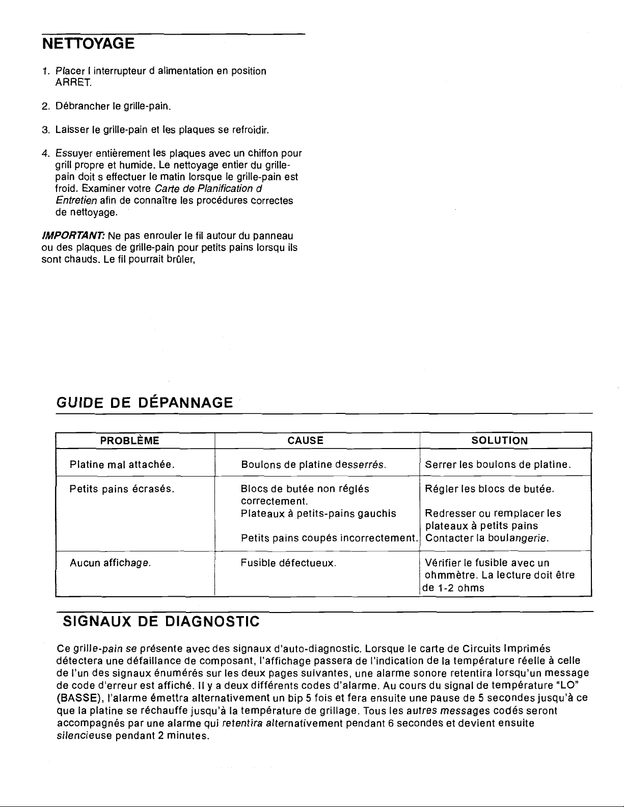
CLEANING
1. Press the power switch to the off position.
2. Unplug toaster.
3. Allow toaster and platens to cool down.
4. Wipe entire platen with clean, damp grill cloth.
Full toaster cleaning must be done in the morning when toaster is cold. See your Planned
Maintenance Card for proper cleaning procedures.
IMPORTANT: Do not drape cord over hot toaster
bun board or platen. This will cause cord to burn.
TROUBLESHOOTING GUIDE
PROBLEM CAUSE SOLUTION
Platen loose. Platen bolts loose. Tighten platen bolts.
Buns being crushed. Stop blocks not adjusted Adjust stop blocks.
properly.
Warped bun trays. Straighten or replace bun
trays.
Contact Bakery.
No Display. Fuse Defective. Check fuse with ohmmeter,
reading should be 1-2 ohms.
DIAGNOSTIC SIGNALS
This toaster comes with self-diagnostic signals. When the P.C. Board senses a component
failure, the display will change from showing the actual temperature to one of the signals
listed on the following two pages, an audio alarm will sound when an error cole message is
displayed. There are two different error code alarms. During a “LO” temp signal, the alarm
will alternately beep 5 times then pause for 5 seconds until the platen heats back up to the
toasting temperature. All other error code messages will be accompanied by an alarm that
alternately sounds for 6 seconds then goes silent for 2 minutes.
2000 McDonald’s Corporation Part No. 411-543 Rev C Printed in the
All Rights Reserved United States of America
8
Page 9
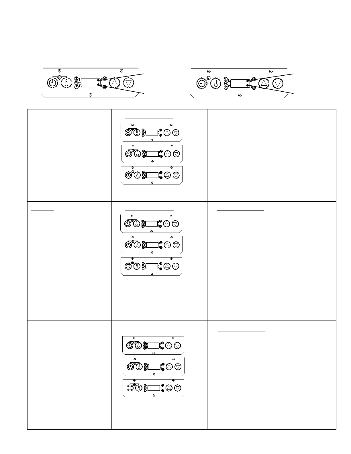
9
E01
Upper Heat
Indicator Light
Lower Heat
Indicator Light
Solid State Toaster Diagnostic Chart
When a part or parts fail in the 213, 416 or 411 Solid State Toasters an ERROR CODE will flash in the display (see figures
below) and an audio alarm will sound. The troubleshooting chart below will explain each error code and what action to
take to determine which component has failed. A “0” on the left means there is a lower circuit failure, a “0” on the right
means there is a upper circuit failure.
UPPER CIRCUIT FAILURE LOWER CIRCUIT FAILURE
E10
Upper Heat
Indicator Light
Lower Heat
Indicator Light
EO1
E1O
E1 1
Diagnostic Codes
Lower platen over heating.
Upper platen over heating.
Both platens over heating.
Problem
Corrective Action
EO2
E2O
E2 2
Diagnostic Codes
Lower probe open.
Upper probe open.
Both probes open.
Problem
Disconnect the corresponding probe and
measure the probe resistance.
The corresponding probe is inoperable if:
The platen temperature is less than 25°C
and the resistance is greater than 1100 ohms.
The platen temperature is less than 100°C
and the resistance is greater than 1381 ohms.
The platen temperature is less than 200°C
and the resistance is greater than 1744 ohms.
IMPORTANT NOTE: If the probe resistance
is correct, check the corresponding probe
connection on the printed circuit board. If the
connection is secure, the printed circuit board
is inoperable.
Corrective Action
Lower platen over heating.
Lower probe open.
Upper platen over heating.
Upper probe open.
Both platens over heating.
Both probes open.
Problem
EO3
E3O
E33
Diagnostic Codes
Corrective Action
Go to failures 01 and 02 above for
corrective action steps to take for a
03 error code.
Go to failures 10 and 20 above for
corrective action steps to take for a
30 error code.
Go to failures 11 and 22 above for
corrective action steps to take for a
33 error code.
With platen heat indicator light off, if voltage
across terminals 3/A1 and 4/A4 of the
corresponding relay is greater than 2.5 volts,
the printed circuit board is inoperable.
Turn power off and disconnect line cord,
disconnect the wire lead from terminal 2/T1 of
the corresponding relay.Measure the resistance across 2/T1 and 1/L1, if resistance is
less than 50K ohms, the corresponding relay
is inoperable.
Page 10
10
With platen heat indicator light on, if voltage
across terminals 3/A1 and 4/A4 of the
corresponding relay is less than 4 volts, the
printed cicuit board is inoperable.
With platen on, measure the AC voltage across
terminals 2/T1 and 1/L1 of the corresponding
relay, if voltage is greater than 2 VAC, the
corresponding relay is inoperable.
IMPORTANT NOTE: E04, E40, and E44
error codes indicate the platen temperatures
have dropped 30°C below the set point
temperature and may be caused by the
following:
1. Cool air blowing on the platens.
2. Low voltage applied to the toaster.
3. Continued toasting during “LO” temp
periods.
4. Inoperable printed circuit board.
Turn the power off, disconnect one side of the
platen and check the platen resistance.
See below: Cold readings are below 50°C
Hot readings are above 200°C
Model 411 series toaster is:
27.8 ohms cold to 32.4 ohms hot.
Model 213 series toaster is:
23 ohms cold to 26.7 ohms hot.
Model 416 series toaster is:
41.8 ohms cold to 48.6 ohms hot
EO4
E4O
E44
Diagnostic Codes
Lower platen under heating.
Upper platen under heating.
Both platens under heating.
Problem
Corrective Action
EO5
E5O
E55
Lower platen under heating.
Upper platen under heating.
Both platens under heating.
EO6
E6O
E66
Lower platen under heating.
Lower probe open.
Upper platen under heating.
Upper probe open.
Both platens under heating.
Both probes open.
Diagnostic Codes
Problem
Corrective Action
Go to E02 and E04 corrective action.
Go to E20 and E40 corrective action.
Go to E22 and E44 corrective action.
Diagnostic CodesProblem
Corrective Action
Go to E01 and E04 corrective action.
Go to E10 and E40 corrective action.
Go to E11 and E44 corrective action.
Page 11
11
EO7
E7O
E77
Lower platen under heating.
Lower platen over heating.
Lower probe open.
Upper platen under heating.
Upper platen over heating.
Upper probe open.
Both platens under heating.
Both platens over heating.
Both probes open.
Diagnostic CodesProblem Corrective Action
Go to E01, E02 and E04 corrective action.
Go to E01, E20 and E40 corrective action.
Go to E11, E22 and E44 corrective action.
EO8
E8O
E88
Lower probe circuit failure.
Upper probe circuit failure.
Both probe circuits failure.
Diagnostic Codes
Problem
Corrective Action
Go to E02 corrective action, replace the item
indicated by the test result.
Go to E20 corrective action, replace the item
indicated by the test result.
Go to E22 corrective action, replace the item
indicated by the test result.
EO9
E9O
E99
Lower platen over heating.
Lower probe open.
Upper platen over heating.
Upper probe open.
Both platens over heating.
Both probes open.
Diagnostic Codes
Problem
Corrective Action
Go to E01 and E08 corrective action.
Go to E01 and E80 corrective action.
Go to E11 and E88 corrective action.
Page 12
12
Page 13
Page 14
Page 15
Page 16
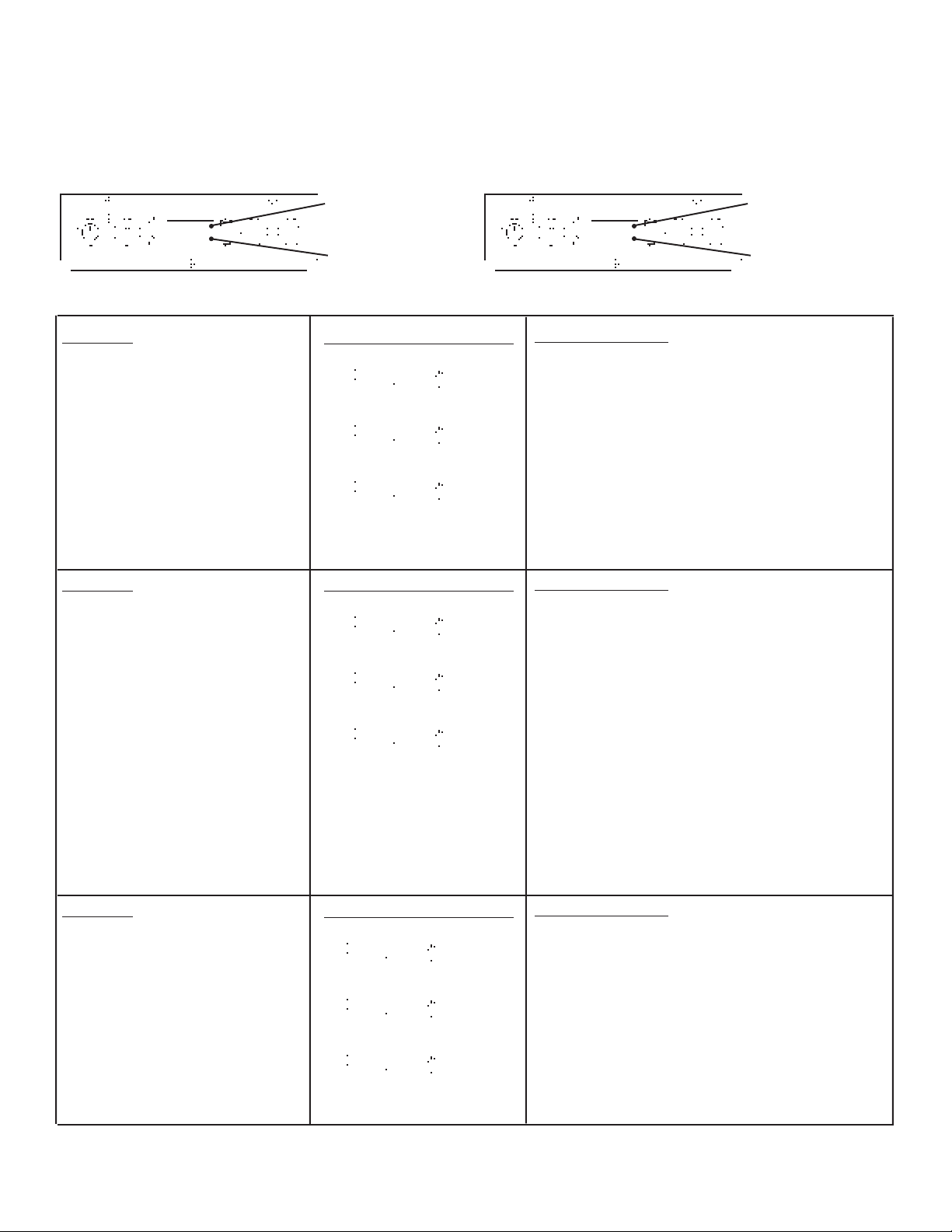
Fiche diagnostique pour grille-pain à semi-conducteurs
Quand une ou des pièces de grille-pain à semi-conducteur des séries 213, 416 ou 411 font défaut, un CODE
D’ERREUR clignotera sur l’indicateur (voir les figures ici-bas) et une alarme sonore se fera entendre. Le guide de
dépannage ci-dessous expliquera chaque code d’erreur et ce qui devra être fait afin de déterminer quel composant a fait
défaut. Un “O” à gauche veut dire qu’il y a une panne du circuit inférieur. Un “O” à droite veut dire qu’il y a une panne
du circuit supérieur.
Voyant indicateur pour
chaleur supérieure
E10 E01
Voyant indicateur pour
chaleur inférieure
Voyant indicateur pour
chaleur supérieure
Voyant indicateur pour
chaleur inférieure
PANNE DU CIRCUIT SUPÉRIEUR PANNE DU CIRCUIT INFERIEURE
Problème
• La plaque inférieure surchauffe.
• La plaque supérieure surchauffe.
• Les deux plaques surchauffent.
Problème
• La sonde inférieure est ouverte.
• La sonde supérieure est ouverte.
• Les deux sondes sont ouvertes.
Codes des diagnostiques
E01
E10
E11
Codes des diagnostiques
E02
E20
E22
Mesure corrective
• Si le voyant de l’indicateur de chaleur est éteint
et le voltage des terminaux 3/A1 et 4/A4 des
relais correspondants est plus élevé que 2,5
Volts, la carte de circuits imprimés ne peut
fonctionner.
• Éteignez le circuit d’alimentation, déconnectez le
cordon électrique et déconnectez le fil conducteur du terminal 2/T1 du relais correspondant.
Mesurez la résistance du 2/T1 et du 1/L1. Si la
résistance est inférieure à 50K ohms, le relais
correspondant ne fonctionne pas.
Mesure corrective
• Déconnectez la sonde correspondante et
mesurez la résistance de la sonde.
La sonde correspondante ne fonctionne pas si:
• La température de la plaque est inférieure à
25°C et la résistance est supérieure à 1100 ohms.
• La température de la plaque est inférieure à
100°C et la résistance est supérieure à 1381 ohms.
• La température de la plaque est inférieure à
200°C et la résistance est supérieure à 1744 ohms.
NOTE IMPORTANTE:
Si la résistance de la
sonde est juste, vérifiez la connexion de la sonde
correspondante sur la carte de circuits imprimés.
Si la connexion est sûre, la carte de circuits
imprimés ne fonctionne pas.
Problème
Codes des diagnostiques
Mesure corrective
• Revoir les pannes 01 et 02 décrites plus haut
• La plaque inférieure surchauffe.
La sonde inférieure est ouverte.
E03
afin de vérifier les mesures correctives à
prendre pour le code d’erreur 03.
• Revoir les pannes 10 et 20 décrites plus haut
• La plaque supérieure surchauffe.
La sonde supérieure est ouverte.
• Les deux plaques surchauffent.
Les deux sondes sont ouvertes.
2000 McDonald’s Corporation Part No. 411-543B Rev. B Printed in the
All Rights Reserved United States of America
E30
E33
afin de vérifier les mesures correctives à
prendre pour le code d’erreur 30.
• Revoir les pannes 11 et 22 décrites plus haut
afin de vérifier les mesures correctives à
prendre pour le code d’erreur 33.
16
Page 17
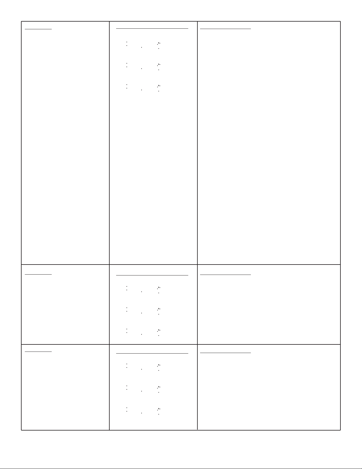
Problème
• Réchauffement insuffisant de
la plaque inférieure.
• Réchauffement insuffisant
de la plaque supérieure.
• Réchauffement insuffisant
des deux plaques.
Codes des diagnostiques
E04
E40
E44
Mesure corrective
• Si le voyant de l’indicateur de chaleur est allumé
et le voltage des terminaux 3/A1 et 4/A4 des
relais correspondants est plus élevé que 4 Volts,
la carte de circuits imprimés ne peut fonctionner.
• Avec la plaque allumée, mesurez le voltage CA
des terminaux 2/T1 et 1/L1 du relais correspondant. Si le voltage est supérieur à 2 VCA, le
relais correspondant ne peut fonctionner.
NOTE IMPORTANTE: Les codes d’erreur E04,
E40 ET E44 indiquent une baisse des températures des plaques de 30°C au-dessous du seuil
de température et peuvent être causés par les
problèmes suivants:
1. Air froid qui souffle sur les plaques.
2. Bas voltage appliqué sur le grille-pain.
3. Usage continu du grille-pain durant les
périodes de température “LO”.
4. Carte des circuits imprimés ne fonctionne pas.
• Éteignez le circuit d’alimentation électrique,
déconnectez un côté de la plaque et vérifiez la
résistance de la plaque chauffante. Voir
cidessous: Lecture des températures froides est
au-dessous de 50°C. Lecture des températures
chaudes est au-dessus de 200°C.
• Modèle de grille-pain de la série 411 est: 27,8
ohms froid à 32,4 ohms chaud.
• Modèle de grille-pain de la série 213 est: 23 ohms
froid à 26.7 ohms chaud.
• Modèle de grille-pain de la série 416 est: 41,8
ohms froid à 48,6 chaud.
Problème
• Réchauffement insuffisant
de la plaque inférieure.
• Réchauffement insuffisant
de la plaque supérieure.
Codes des diagnostiques
E05
E50
Mesure corrective
• Passez aux mesures correctives E01 et E04.
• Passez aux mesures correctives E10 et E40.
• Passez aux mesures correctives E11 et E44.
• Réchauffement insuffisant
des deux plaques.
Problème
• Réchauffement insuffisant
de la plaque inférieure. La
sonde inférieure est ouverte.
• Réchauffement insuffisant
de la plaque supérieure. La
Codes des diagnostiques
E55
E06
E60
Mesure corrective
• Passez aux mesures correctives E02 et E04.
• Passez aux mesures correctives E20 et E40.
• Passez aux mesures correctives E22 et E44.
sonde supérieure est ouverte.
• Réchauffement insuffisant
E66
des deux plaques. Les deux
sondes sont ouvertes.
2000 McDonald’s Corporation Part No. 411-543B Rev. B Printed in the
All Rights Reserved United States of America
17
Page 18

Problème
• Réchauffement insuffisant
de la plaque inférieure.
La plaque inférieure
surchauffe.
La sonde inférieure est
ouverte.
Codes de diagnostiques
E07
E70
Mesure corrective
• Passez aux mesures correctives E01, E02 et E04.
• Passez aux mesures correctives E01, E20 et E40.
• Réchauffement insuffisant
de la plaque supérieure.
La plaque supérieure
surchauffe.
La sonde supérieure est
ouverte.
• Réchauffement insuffisant
des deux plaques.
Les deux plaques
surchauffent.
Les deux sondes sont
ouvertes.
Problème
• Panne du circuit sonde
inférieure.
• Panne du circuit sonde
supérieure.
• Panne du circuit des deux
sondes.
E77
Codes de diagnostiques
E08
E80
E88
• Passez aux mesures correctives E11, E22 et E44.
Mesure corrective
• Passez à la mesure corrective E02 et remplacer
l’article indiqué par le résultat de l’essai.
• Passez à la mesure corrective E20 et remplacer
l’article indiqué par le résultat de l’essai.
• Passez à la mesure corrective E22 et remplacer
l’article indiqué par le résultat de l’essai.
Problème
• La plaque inférieure
surchauffe. La sonde
inférieure est ouverte.
• La plaque supérieure
surchauffe. La sonde
supérieure est ouverte.
Codes de diagnostiques
E09
E90
Mesure corrective
• Passez aux mesures correctives E01, et E08.
• Passez aux mesures correctives E01 et E80.
• Passez aux mesures correctives E11 et E88.
• Les deux plaques surchauffent. Les deux sondes sont
E99
ouvertes.
2000 McDonald’s Corporation Part No. 411-543 Rev C. Printed in the
All Rights Reserved United States of America
18
Page 19
Page 20
Page 21

Page 22

Page 23

Diagnose Karte für monolithischer Toaster
Als ein Teil oder Teile nicht werken in den monolithischen Toasters 213, 416, oder 411, eine Fehlercode erscheint (siehe
die nachfolgende Abbildung) und ein Audioalarm ertönt. Die nachfolgende Karte zur Fehlerbeseitigung erklärt jede
Fehlercode und wie man entscheidet welche Komponente nicht funktioniert. Ein “O” am links bedeutet ein Fehler des
unteren Temperaturfühler; ein “O” am rechts bedeutet ein Fehler des oberen Temperaturfühler.
Obere Heizanzeige
Obere Heizanzeige
E10 E01
Untere Heizanzeige
FEHLER DES OBEREN TEMPERATURFÜHLER FEHLER DES UNTEREN TEMPERATURFÜHLER
Problem
Diagnose-Code
Verbessernde Handlung
• Mit der Heizanzeige der Platte ausleuchtet,
• Untere Heizplatte überhitzt.
• Obere Heizplatte überhitzt.
• Beide Heizplatten überhitzen.
E01
E10
wenn die Spannung von 3/A1 bis 4/A4 des
entsprchender Relais ist mehr als 2.5 volts,
dann ist die Hauptschaltkarte unterbrochen.
• Den Strom ausschalten und die Kabel ziehe,
der Haupdraht von den 2/T1 des entsprchender
Relais ziehen. Machen einen Messer der
E11
Festigheit von 2/T1 bis 1/L1. Wenn die
Festigheit ist weniger als 50K ohms, dann ist
das entsprchende Relais unterbrochen.
Problem
• Unterbrechung des unteren
Temperaturfühlers.
Diagnose-Code
E02
erbessernde Handlung
V
• Ziehen den entsprchenden Sensor ab und
machen einen Messer der Festigheit des
Sensors. Der entsprchender Sensor ist
• Unterbrechung des oberen
Temperaturfühlers.
E20
unterbrochen wenn:
• Die temperatur der Platte ist weniger als 25°C
und die Festigheit ist mehr als 1100 ohms.
• Unterbrechung den beiden
Temperaturfühlers.
E22
• Die temperatur der Platte ist weniger als 100°C
und die Festigheit ist mehr als 1381 ohms.
• Die temperatur der Platte ist weniger als 200°C
und die Festigheit ist mehr als 1744 ohms.
WICHTIG:
Als die Festigheit des Sensors hat
Rechts, prüfen Sie die Verbindung des
entsprechender Sensor auf der
Hauptschaltkarte. Als die Verbindung eng ist, ist
die Hauptschaltkarte verbrochen.
Untere Heizanzeige
Problem
Diagnose-Code
V
erbessernde Handlung
• Siehe Fehler 01 und 02 oben für Verbessernde
• Untere Heizplatte überhitzt.
E03
Handlung für eine Fehlercode 03.
Unterbrechung des unteren
Temperaturfühlers.
• Obere Heizplatte überhitzt.
Unterbrechung des oberen
Temperaturfühlers.
E30
E33
• Siehe Fehler 10 und 20 oben für Verbessernde
Handlung für eine Fehlercode 30.
• Siehe Fehler 11 und 22 oben für Verbessernde
Handlung für eine Fehlercode 33.
• Beide Heizplatten überhitzen.
Unterbrechung den beiden
Temperaturfühlers.
2000 McDonald’s Corporation Part No. 411-543 Rev C Printed in the
All Rights Reserved United States of America
23
Page 24

Problem
Diagnose-Code
Verbessernde Handlung
• Untere Heizplatte erreicht
nicht die gewünschte
Temperatur.
• Obere Heizplatte erreicht
nicht die gewünschte
Temperatur.
• Beide Heizplatten erreichen
nicht die gewünschte
Temperatur.
E04
E40
E44
• Mit der Heizanzeige der Platte aufleuchtet, wenn
die Spannung von 3/A1 bis 4/A4 des entsprchender Relais ist mehr als 4 volts, dann ist die
Hauptschaltkarte unterbrochen.
• Mit der Platte ausleuchtet, machen einen Messer
der Spannung AC von 2/T1 bis 1/L1 des entsprchender
Relais. Wenn die Spannung mehr als 2 VAC ist,
dann ist das entsprchender Relais unterbrochen.
WICHTIG: Wenn die E04, E40, und E44
Fehlercode leuchtet ist die Plattetemperaturen
30°C weniger als die programmierte
Temperaturen und die Gründe folgenden:
1. Auf kalte Zugluft um den Platten.
2. Nicht genug Spannung zum Toaster.
3. Wann der Toaster hat “LO” Temperaturen,
erforsetzt.
4. Hauptschaltkarte unterbrochen.
• Den Strom ausschalten, ziehen eine Seite der
Platte und prüfen die Festigheit de Platte.
Vergleichen Sie dazu.
Kalte Temperaturen sind weniger als 50°C
Heize Temperaturen sind mehr als 200°C
• Toaster Modell der Serie 411 ist: 27.8 ohms kalt
bis 32.4 ohms heiz.
• Toaster Modell der Serie 213 ist: 23 ohms kalt bis
26.7 ohms heiz.
• Toaster Modell der Serie 416 ist: 41.8 ohms kalt
bis 48.6 ohms heiz.
Problem
• Untere Heizplatte erreicht
Diagnose-Code
E05
Verbessernde Handlung
• Siehe E01 und E04 Verbessernde Handlung.
nicht die gewünschte
Temperatur.
• Obere Heizplatte erreicht
nicht die gewünschte
E50
• Siehe E10 und E40 Verbessernde Handlung.
• Siehe E11 und E44 Verbessernde Handlung.
Temperatur.
• Beide Heizplatten erreichen
E55
nicht die gewünschte
Temperatur.
V
Problem
Diagnose-Code
erbessernde Handlung
• Untere Heizplatte erreicht
nicht die gewünschte
Temperatur. Unterbrechung
des unteren
Temperaturfühlers.
• Obere Heizplatte erreicht nicht
E06
E60
• Siehe E02 und E04 Verbessernde Handlung.
• Siehe E20 und E40 Verbessernde Handlung.
• Siehe E22 und E44 Verbessernde Handlung.
die gewünschte Temperatur.
Unterbrechung des oberen
Temperaturfühlers.
E66
• Beide Heizplatten erreichen
nicht die gewünschte
Temperatur. Unterbrechung
den beiden Temperaturfühlers.
2000 McDonald’s Corporation Part No. 411-543 Rev C Printed in the
All Rights Reserved United States of America
24
Page 25

Problem
• Untere Heizplatte erreicht
nicht die gewünschte
Temperatur.
Untere Heizplatte überhitzt.
Unterbrechung des unteren
Temperaturfühlers.
Diagnose-Code
E07
E70
Verbessernde Handlung
• Siehe E01, E02 and E04 Verbessernde
Handlung.
• Siehe E01, E20 and E40 Verbessernde
Handlung.
• Obere Heizplatte erreicht
nicht die gewünschte
Temperatur.
Obere Heizplatte überhitzt.
Unterbrechung des oberen
Temperaturfühlers.
• Beide Heizplatten erreicht
nicht die gewünschte
Temperatur.
Beide Heizplatten überhitzen.
Unterbrechung den beiden
Temperaturfühlers.
Problem
• Fehler des unteren
TemperaturfühlerStromkreises.
• Fehler des unteren
TemperaturfühlerStromkreises.
• Fehler des unteren
TemperaturfühlerStromkreises.
E77
Diagnose-Code
E08
E80
E88
• Siehe E11, E22 and E44 Verbessernde
Handlung.
Verbessernde Handlung
• Siehe E02 Verbessernde Handlung, auswechseln den Artikel den mit dem Test angezeigt ist.
• Siehe E20 Verbessernde Handlung, auswechseln den Artikel den mit dem Test angezeigt ist.
• Siehe E22 Verbessernde Handlung, auswechseln den Artikel den mit dem Test angezeigt ist.
Problem
• Untere Heizplatte überhitzt.
Unterbrechung des unteren
Temperaturfühlers.
• Obere Heizplatte überhitzt.
Unterbrechung des oberen
Diagnose-Code
E09
E90
Verbessernde Handlung
• Siehe E01 and E08 Verbessernde Handlung.
• Siehe E01 and E80 Verbessernde Handlung.
• Siehe E11 and E88 Verbessernde Handlung.
Temperaturfühlers.
• Beide Heizplatten überhitzen.
E99
Unterbrechung den beiden
Temperaturfühlers.
2000 McDonald’s Corporation Part No. 411-543 Rev C Printed in the
All Rights Reserved United States of America
25
Page 26

Page 27

Page 28

Page 29

Page 30

Scheda diagnostica per Tostapane elettronico
Quando un componente o dei componenti si guastano nei Tostapane a stato solido 213, 416 o 411 viene visualizzato un
CODICE ERRORE lampeggiante (vedere figure sotto) ed entra in funzione un allarme sonoro. La seguente scheda per
la localizzazione dei guasti contiene la spiegazione di ciascun codice errore e le indicazioni degli interventi necessari per
determinare quale componente si è guastato. Una “O” sulla sinistra indica che c’è un guasto del circuito inferiore; una
“O” sulla destra indica che c’è un guasto nel circuito superiore.
Spia calore della
piastra superiore
Spia calore della
piastra superiore
E10 E01
Spia calore della
piastra inferiore
GUASTO CIRCUITO SUPERIORE GUASTO CIRCUITO INFERIORE
Spia calore della
piastra inferiore
Problema
• Surriscaldamento piastra
inferiore.
• Surriscaldamento piastra
superiore.
• Surriscaldamento delle due
piastre.
Problema
• Sonda inferiore aperta.
• Sonda superiore aperta.
• Le due sonde sono aperte.
Codici diagnostici
E01
E10
E11
Diagnose-Code
E02
E20
E22
Intervento correttivo
• Con la spia calore della piastra spenta, se il
voltaggio tra i terminali 3/A1 e 4/A4 dei relè
corrispondenti è maggiore di 2,5 volt, la scheda
del circuito stampato è fuori uso.
• Spegnere l’interruttore e scollegare il cavo d’alimentazione, scollegare i fili dal terminale 2/T1
dal relè corrispondente. Misurare la resistenza
tra 2/T1 e 1/L1. Se la resistenza è inferiore ai
50K ohm, il relè corrispondente è fuori uso.
Intervento correttivo
• Scollegare la sonda corrispondente e misurare la
resistenza della sonda. La sonda corrispon-
dente è fuori uso se:
• La temperatura della piastra è inferiore ai 25°C e
la resistenza è maggiore di 1100 ohm.
• La temperatura della piastra è inferiore ai 100°C
e la resistenza è maggiore di 1381 ohm.
• La temperatura della piastra è inferiore ai 200°C
e la resistenza è maggiore di 1744 ohm.
NOTA IMPORTANTE:
Se la resistenza della sonda
è corretta, controllare la connessione della sonda
corrispondente sulla scheda del circuito stampato.
Se la connessione è a ben salda, la scheda del
circuito stampato è fuori uso.
Problema
Diagnose-Code
Intervento correttivo
• Vedere sopra i guasti 01 e 02 per i passi degli
• Surriscaldamento piastra
inferiore. Sonda inferiore aperta.
• Surriscaldamento piastra
superiore. Sonda superiore
aperta.
• Surriscaldamento delle due
piastre. Le due sonde sono
aperte.
2000 McDonald’s Corporation Part No. 411-543 Rev C Printed in the
All Rights Reserved United States of America
E03
E30
E33
interventi correttivi da intraprendere per un
codice errore 03.
• Vedere sopra i guasti 10 e 20 per i passi degli
interventi correttivi da intraprendere per un
codice errore 30.
• Vedere sopra i guasti 11 e 22 per i passi degli
interventi correttivi da intraprendere per un
codice errore 33.
30
Page 31

Problema
• Scarso riscaldamento piastra
inferiore.
• Scarso riscaldamento piastra
superiore.
• Scarso riscaldamento delle
due piastre.
Codici diagnostici
E04
E40
E44
Intervento correttivo
• Con la spia calore della piastra accesa, se il
voltaggio tra i terminali 3/A1 e 4/A4 dei relè
corrispondenti è inferiore a 4 volt, la scheda del
circuito stampato è fuori uso.
• Con la piastra accesa, misurare il voltaggio AC
tra i terminali 2/T1 e 1/L1 dei relè corrispondenti:
se il voltaggio è maggiore di 2 VAC, il relè
corrispondente è fuori uso.
NOTA IMPORTANTE: i codici errore E04, E40, e
E44 indicano che le temperature delle piastre
sono scese di 30°C al di sotto della temperatura
di funzionamento impostata; ciò può essere
dovuto a quanto segue:
1. Flusso di aria fredda sulle piastre.
2. Voltaggio insufficiente applicato al tostapane.
3. Uso continuato del tostapane durante i periodi
di temperatura “LO”.
4. Scheda del circuito stampato fuori uso.
• Spegnere l’interruttore, scollegare un lato della
piastra e controllare la resistenza della piastra.
Vedere sotto: le letture fredde sono al di sotto dei
50°C Le letture calde sono al di sporta dei 200°C
Problema
• Scarso riscaldamento piastra
inferiore.
• Scarso riscaldamento piastra
superiore.
• Scarso riscaldamento delle
due piastre.
Problema
• Scarso riscaldamento piastra
inferiore. Sonda inferiore aperta.
• Scarso riscaldamento piastra
superiore. Sonda superiore
aperta.
Codici diagnostici
E05
E50
E55
Codici diagnostici
E06
E60
• Per il modello della serie tostapane 411: da 27,8
ohm freddo a 32,4 ohm caldo.
• Per il modello della serie tostapane 213: da 23
ohm freddo a 26,7 ohm caldo.
• Per il modello della serie tostapane 416: da 41,8
ohm freddo a 48,6 ohm caldo.
Intervento correttivo
• Passare agli interventi correttivi E01 e E04.
• Passare agli interventi correttivi E10 e E40.
• Passare agli interventi correttivi E11 e E44.
Intervento correttivo
• Passare agli interventi correttivi E02 e E04.
• Passare agli interventi correttivi E20 e E40.
• Passare agli interventi correttivi E22 e E44.
• Scarso riscaldamento delle
due piastre. Le due sonde
E66
sono aperte.
2000 McDonald’s Corporation Part No. 411-543 Rev C Printed in the
All Rights Reserved United States of America
31
Page 32

Problema
Codici diagnostici
Intervento correttivo
• Scarso riscaldamento piastra
inferiore.
Surriscaldamento piastra
inferiore.
Sonda inferiore aperta.
• Scarso riscaldamento piastra
superiore.
Surriscaldamento piastra
superiore.
Sonda superiore aperta.
• Scarso riscaldamento delle
due piastre.
Surriscaldamento delle due
piastre.
Le due sonde sono aperte.
Problema
• Guasto del circuito della
sonda inferiore.
• Guasto del circuito della
sonda superiore.
• Guasto del circuito delle due
sonde.
E07
E70
E77
Codici diagnostici
E08
E80
E88
• Passare agli interventi correttivi E01, E02 e E04.
• Passare agli interventi correttivi E01, E20 e E40.
• Passare agli interventi correttivi E11, E22 e E44.
Intervento correttivo
• Passare all’intervento correttivo E02 e sostituire
l’elemento indicato dal risultato della prova.
• Passare all’intervento correttivo E20 e sostituire
l’elemento indicato dal risultato della prova.
• Passare all’intervento correttivo E22 e sostituire
l’elemento indicato dal risultato della prova.
Problema
• Surriscaldamento piastra
inferiore. Sonda inferiore
Diagnose-Code
E09
Intervento correttivo
• Passare agli interventi correttivi E01 e E08.
aperta.
• Surriscaldamento piastra
E90
• Passare agli interventi correttivi E01 e E80.
superiore. Sonda superiore
aperta.
• Surriscaldamento delle due
E99
• Passare agli interventi correttivi E11 e E88.
piastre. Le due sonde sono
aperte.
2000 McDonald’s Corporation Part No. 411-543 Rev C Printed in the
All Rights Reserved United States of America
32
Page 33

Page 34

Page 35

Page 36

Page 37

Carta diagnóstica para Tostadoras de Estado Sólido
Cuando un piezo o piezos no funciona en los tostadoras de estado sólido un código de error [ERROR CODE] muestra
en la pantalla (ver las figuras abajo) y se escuchará una alarma audible. La guía para la resolución de problemas explicará cada código de error y como determinar cual componente no funciona. Cuando aparece un “O” a la izquierda el
circuito inferior falta.
Luz del indicador del
calentador superior
E10 E01
Luz del indicador del
calentador inferior
FALTA DE CIRCUITO SUPERIOR FALTA DE CIRCUITO INFERIOR
Problema
• Plato inferior calenta
demasiado.
• Plato superior calenta
demasiado.
• Los dos platos calentan
demasiado.
Problema
• Sonda inferior abierta.
• Sonda superior abierta.
• Los dos sondas abiertas.
Códigos diagnósticos
E01
E10
E11
Códigos diagnósticos
E02
E20
E22
Acción Correctiva
• Cuando el luz del indicador del calentador del
plato no está iluminada, si el voltaje de terminales 3/Al a 4/A4 del relevador correspondiente
está más de 2,5 voltios, el tablero impreso del
circuito está inoperable.
• Desactive la potencia y desconecte la cuerda de
línea, desconecte el guía del cable de terminal
2/T1 de relevador correspondiente. Mida la
resistencia de 2/Tl y 1/L1. Si la resistencia está
menos de 5OK ohmios, el relevador correspondiente está inoperable.
Acción Correctiva
• Desconecte la sonda correspondiente y mida la
resistencia de la sonda. La sonda correspondi-
ente está inoperable si:
• La temperatura del plato está menos de 25°C y
la resistencia está más de 1100 ohmios.
• La temperatura del plato está menos de 100°C y
la resistencia está más de 1381 ohmios.
• La temperatura del plato está menos de 200°C y
la resistencia está más de 1744 ohmios.
Luz del indicador del
calentador superior
Luz del indicador del
calentador inferior
NOTA IMPORTANTE:
Si la resistencia de la
sonda está correcta, verifique la conexión de la
sonda correspondiente en el tablero impreso del
circuito. Si la conexión está segura, el tablero
impreso del circuito está inoperable.
Problema
• Plato inferior calenta demasiado.
Códigos diagnósticos
E03
Sonda inferior abierta.
• Plato superior calenta demasiado.
E30
Sonda superior abierta.
• Los dos platos calenta demasiado.
E33
Los dos sondas abiertas.
2000 McDonald’s Corporation Part No. 411-543 Rev C Printed in the
All Rights Reserved United States of America
Acción Correctiva
• Ir a las faltas 01 y 02 arriba para etapas de
acción correctiva para el código de error 03.
• Ir a las faltas 10 y 20 arriba para etapas de
acción correctiva para el código de error 30.
• Ir a las faltas 11 y 22 arriba para etapas de
acción correctiva para el código de error 33.
37
Page 38

Problema
• Plato inferior calenta
insuficiente.
• Plato superior calenta
insuficiente.
• Los dos platos calentan
insuficiente.
Códigos diagnósticos
E04
E40
E44
Acción Correctiva
• Cuando el luz del indicador del calentador del
plato está iluminada, si el voltaje de terminales
3/Al a 4/A4 del relevador correspondiente está
menos de 4 voltios, el tablero impreso del
circuito está inoperable.
• Cuando el plato está activado, mida el voltaje
CA desde los terminals 2/T1 a 1/Ll del relevador
correspondiente, si el voltaje está más de 2
VCA, el relevador está inoperable.
NOTA IMPORTANTE: Códigos de error E04,
E40, y E44 indica que las temperaturas del plato
disminuen 30°C debajo de la temperatura
programada “set point” y los siguientes puede
causarlo:
1. Aire fría en los platos.
2. Voltaje insuficiente en la tostadora.
3. La tostadora continua durante de los periodos
de temp “‘LO”.
4. Tablero impreso del circuito inoperable.
• Desactive la potencia, desconecte un lado del
plato y verifique la resistencia del plato. Ver
abajo: Medidas frías están menos de 50°C.
Medidas calientes están más de 200°C.
Problema
• Plato inferior calenta
insuficiente.
• Plato superior calenta
insuficiente.
• Los dos platos calentan
insuficiente.
Problema
• Plato inferior calenta insufuciente. Sonda inferior abierta.
• Plato superior calenta insufuciente. Sonda superior abierta.
Códigos diagnósticos
E05
E50
E55
Códigos diagnósticos
E06
E60
• La tostadora modelo serie 411 está: 27,8 ohmios
fría a 32,4 ohmios caliente.
• La tostadora modelo serie 213 está: 23 ohmios
fría a 26,7 ohmios caliente.
• La tostadora modelo serie 416 está: 41,8
ohmios fría a 48,6 ohmios caliente.
Acción Correctiva
• Ir a E01 y E04 acción correctiva.
• Ir a E10 y E40 acción correctiva.
• Ir a E11 y E44 acción correctiva.
Acción Correctiva
• Ir a E02 y E04 acción correctiva.
• Ir a E20 y E40 acción correctiva.
• Los dos platos calentan insufuciente. Los dos sondas
E66
• Ir a E22 y E44 acción correctiva.
abiertas.
2000 McDonald’s Corporation Part No. 411-543 Rev C Printed in the
All Rights Reserved United States of America
38
Page 39

Problema
• Plato inferior calenta
insufuciente.
Plato inferior calenta
demasiado.
Sonda inferior abierta.
• Plato superior calenta
insufuciente.
Plato superior calenta
demasiado.
Sonda superior abierta.
• Los dos platos calentan
insufuciente.
Los dos platos calentan
demasiado.
Los dos sondas abiertas.
Códigos diagnósticos
E07
E70
E77
Acción Correctiva
• Ir a E01, E02 y E04 acción correctiva .
• Ir a E01, E20 y E40 acción correctiva .
• Ir a E11, E22 y E44 acción correctiva .
Problema
• Falta del circuito de sonda
inferior.
• Falta del circuito de sonda
superior.
• Falta del circuito de falta de
los dos sondas.
Problema
• Plato inferior calenta
demasiado. Sonda inferior
abierta.
• Plato superior calenta
demasiado. Sonda superior
abierta.
• Los dos platos calentan
demasiado. Los dos sondas
abiertas.
Códigos diagnósticos
E08
E80
E88
Códigos diagnósticos
E09
E90
E99
Acción Correctiva
• Ir a E02 acción correctiva , reemplazar el artículo
indicado del resultado de la prueba.
• Ir a E20 acción correctiva , reemplazar el artículo
indicado del resultado de la prueba.
• Ir a E22 acción correctiva , reemplazar el artículo
indicado del resultado de la prueba.
Acción Correctiva
• Ir a E01 y E08 acción correctiva.
• Ir a E01 y E80 acción correctiva.
• Ir a E11 y E88 acción correctiva.
2000 McDonald’s Corporation Part No. 411-543 Rev C Printed in the
All Rights Reserved United States of America
39
Page 40

Page 41

TS 016-i
Toasters
Precaution
During some checks, live electrical circuits will be exposed, and hot toasting
surfaces will be uncovered.
Hazard Communication Standard (HCS) – The procedures on this card
include the use of chemical products. These chemical products will be
highlighted with bold face letters followed by the abbreviation (HCS) in the
tools portion of the procedure. See the Hazard Communication Standard
(HCS) Manual for the appropriate Material Safety Data Sheet(s) (MSDS)
Applying Bun Toaster Release Agent
IMPORTANT: Use only McD Toaster Release Agent on bun toasters.
Other products may damage bun toasters.
1. Dust all loose crumbs from toaster surfaces.
2. Toaster platens must be well rinsed and dry. McD Bun Toaster Release Agent
may be applied to hot toaster platens. Before applying to hot platens, put on
protective gloves.
3. To coat top platen surface, thoroughly wet a clean, folded customer napkin or
paper towel, with Release Agent.
4. Rub a generous amount of Release Agent over entire surface of a platen until well
coated. Use protective gloves and No. 257 cleaning tool.
5. Repeat steps 2 and 3 for other platens, including undersides.
IMPORTANT: Platen undersides and difficult to reach areas can be coated
by placing a folded customer napkin or paper towel with Release Agent on
No. 257 cleaning tool to apply Release Agent to platen surface.
IMPORTANT: Do not wipe toaster with a damp cloth after Release Agent is
applied. This removes Release Agent and causes sticking.
6. If sticking occurs between weekly applications, reapply Release Agent using steps
1-4.
IMPORTANT: Toaster does not need to be recleaned or cooled down before
applying Release Agent.
IMPORTANT: Reapply Release Agent weekly, while toaster is cold between
monthly cleaning, to all platen surfaces.
Toasters
Prince Castle: Bun Toasters
Planned Maintenance
System: Maintenance
Requirement Card
(MRC)
Pictures and additional
information:
Corresponding Chapter of
Equipment Manual
When
Weekly
Tools
McD Bun Toaster Release
Agent (HCS), customer
paper napkins or paper
towels, protective gloves,
257 cleaning tool.
©2000 McDonald’s Corporation
Printed in DEC 00
Revised in SEP 00
Page 1 of 5
Page 42

Check Calibration of Temperature
IMPORTANT: Do not perform this procedure until the toaster has been on
for at least 45 minutes and temperature has stabilized. Do not use the toaster
during this 45-minute period.
1. Place the rear of the bun board on top of the control box and place the rest of the
bun board on top of the platen.
NOTE: On dual platen toasters (411 & 416), the bun board is only required
for use on the top platen.
2. On dual platen toasters, use to select the platen to be calibrated.
3. Center the digital thermometer on the front edge of the platen. When the
corresponding LED on the control panel turns on, immediately record the digital
thermometer temperature reading.
NOTE: On dual platen toasters (411 & 416), perform step 2 on the lower
platen first, then the upper platen.
IMPORTANT: If the temperature reading on the platen is greater than +/3°C (+/-5°F) compared to the toaster temperature display, proceed with step
3 to perform calibration. If temperature reading is within range, toaster is
functioning properly and does not require calibration.
4. Enter the calibration mode by pressing and holding for 6 seconds. A
beep will sound and the LED next to the calibration symbol will turn on. Release
all buttons.
5. Press and release to select upper platen for calibration or to select lower
platen. Allow 10 seconds for the display to stabililize. The display will show the
measured platen temperature value with no offset.
NOTE: On dual platen toasters (411 & 416), calibrate each platen separately.
6. When the corresponding platen LED turns on, use to adjust the display
temperature to match the reading recorded in step 3.
NOTE: Temperature can only be adjusted +/-5°C (+/-9°F).
7. Press to store the new calibrated temperature and to exit calibration mode.
IMPORTANT: After calibration is complete, allow one full heater on/off
cycle to allow the new calibrated temperature to stabilize.
TS 016-i
Toasters
When
Monthly
Tools
Digital thermometer with
surface probe.
©2000 McDonald’s Corporation
Printed in DEC 00
Revised in SEP 00
Page 2 of 5
Page 43

Clean Nickel Platen
PREPARING BUN TOASTER
1. If toaster is cool, heat to operating temperature.
IMPORTANT: Bun toaster must be at operating temperature for cleaning.
2. Turn toaster power switch to OFF position and unplug power cord.
CAUTION: Failure to unplug power cord before cleaning may cause
electrical shock.
3. Remove all buns, bun trays, and bun tray liners from the bun toaster stand.
4. Turn on the grill exhaust fan.
5. Move toaster stand in front of grill.
HOW TO CLEAN
1. Firmly attach McD No-Scratch Pad to cleaning tool. Use only nonabrasive blue
No-Scratch pads designed for grill cleaning. Do not use a green pad. It will
damage platen surface.
2. Pour one packet of McD Hi-Temp Grill Cleaner into a breakfast container base.
3. Put on protective gloves.
4. Turn bun board upside-down and lay on upper platen or plate.
5. Dip No-Scratch Pad into Hi-Temp Grill Cleaner.
6. Spread cleaner over bun board and lightly scrub until clean. Apply additional
cleaner as needed. Place bun board in the back sink area for cooling and rinsing.
7. If toaster is equipped with an aluminum plate, repeat step 6 so both sides of plate
are clean.
8. Dip No-Scratch Pad into cleaner and lightly spread a coasting of cleaner onto top
surface of platen.
IMPORTANT: Do not pour cleaner on surface. Apply only with No-Scratch
Pad and Cleaning Tool. Do not scrub while applying cleaner.
9. Repeat Step 8 for all platen surfaces, including undersides.
10. After repeating cleaner, lightly scrub all platen surfaces (including undersides)
with No-Scratch Pad until all soil liquifies. Apply additional cleaner to cleaning
as needed.
11. Remove No-Scratch Pad from cleaning tool. Fold a clean, damp grill cloth
lengthwise and lay it over the end of the cleaning tool. Thoroughly rinse platens,
including undersides, by wiping with a damp grill cloth. Before wiping platens,
always rinse grill cloth in clear water and wring it out until no soil is seen.
IMPORTANT: Thorough rinsing of the platen is required to ensure proper
release agent performance. Rinse platens with clean grill cloths until no soil
is seen on the cloth.
CAUTION: Do not pour water on platens or use dripping wet grill cloths.
TS 016-i Toasters
When
Monthly
Tools
McD Hi Temp Grill Cleaner
(HCS), McD Bun Toaster
Release Agent (HCS), McD
No Scratch Pad, base of
Big Breakfast container,
No. 257 cleaning tool,
clean grill cloths (qty. 6-8),
customer paper napkins or
paper towels, protective
gloves.
©2000 McDonald’s Corporation
Printed in DEC 00
Revised in SEP 00
Page 3 of 5
Page 44

©2000 McDonald’s Corporation
Printed in DEC 00
Revised in SEP 00
Page 4 of 5
TS 016-i
Toasters
12. Repeat the rinsing procedure in Step 11 with a fresh, clean, damp grill cloth to
ensure all cleaner and soil are removed from platens.
13. Wipe remaining parts of the toaster with a clean damp cloth.
14. Take bun tray platform, bun board, and aluminum plate to back sink. Scrub with
a pot brush or No-Scratch Pad in a solution of McD All Purpose Concentrate.
Do not use abrasive pads. Rinse parts under running water and let air dry.
Tighten Platen and Leg Bolts
TIGHTEN PLATEN BOLTS
1. Turn the power switch to the OFF Position.
2. Unplug the power cord.
3. Allow toaster to cool before proceeding.
4. Using an adjustable wrench, tighten the platen bolts which hold handle in upright
position.
TIGHTEN LEG BOLTS
1. Carefully turn the toaster upside down for access to legs.
2. Adjust and tighten leg bolts to obtain a level setting for toasting.
3. Set toaster right side up and check for level setting.
4. Adjust leg bolts as necessary until toaster sits level.
5. Plug the power cord into the appropriate electrical receptacle.
6. If the toaster is about to be used, turn the power switch to ON position.
When
Monthly
Tools
Adjustable wrench,
flatblade screwdriver
Page 45

©2000 McDonald’s Corporation
Printed in DEC 00
Revised in SEP 00
Page 5 of 5
TS 016-i
Toasters
When
Monthly
Tools
Pliers, hammer, file
Check Bun Tray Platforms, Bun Board, Bun Trays and Spatulas
IMPORTANT: This check procedure should be conducted while the
platforms, trays and spatulas are cold. It should be done for all spatulas,
trays and platforms.
BUN SPATULA
1. Lay the spatula on a flat work table top.
2. Make sure the entire surface is flat, including the front edge. The front end of
bun spatula must be free from necks and burrs.
3. Sharpen front edge of spatula so all nicks and burrs are removed.
IMPORTANT: Straightening curled corners with pliers and hammer middle
part of the tray flat.
BUN TRAY
1. Lay the track on a flat work tabletop and inspect for flatness.
2. Inspect the try for uniform height.
3. Straightened curled corners with pliers and hammer middle part of the tray flat.
BUN TRAY PLATFORM
1. Remove the platform from the lower part of the toaster.
2. Lay the platform on a flat work tabletop and inspect the entire surface to make
sure it is flat.
3. Using pliers or a hammer, straighten as needed.
4. Reinstall the platform into toaster.
BUN BOARD
1. Remove the bun board from toaster.
2. Lay the bun board on a flat work tabletop and inspect for flatness.
3. Measure the distance between the tabletop and the bottom side of the bun board in
the front, center, and rear. It should be approximately 1/2" (13mm) for all
toasters except Big Mac 412 and 416 series, and approximately 1/2" (19cm) for
Big Mac Toasters.
4. Bend as needed to maintain flatness.
Page 46

©2000 McDonald’s Corporation
Printed in DEC 00
Revised in SEP 00
Page 1 of 5
TS 016-i
Grille-pains
Images et informations
additionnelles:
Chapitre correspondant du
manuel d’équipement
Quand
Hebdomadairement
Outils
Agent de démoulage de
grille-petits pains McD
(HSC), serviettes de table
en papier ou essuie-tout
du client, gants
protecteurs, outil de
nettoyage no 257.
Grille-pains
Prince Castle: Grille-petits pains
Précaution
Durant certaines vérifications, les circuits électriques sous tension seront
exposés et les surfaces de grillage chaudes seront découvertes.
Hazard Communication Standard (HCS)- Les procédures sur cette carte
incluent l’utilisation de produits chimiques. Ces produits chimiques seront mis
en surbrillance avec des lettres en gras suivies de l’abréviation (HSC) dans la
partie outils de la procédure. Voir le manuel Hazard Communication Standard
(HSC) pour voir la ou les feuille(s) des Données de sécurité du matériel (FDSM).
Application de l’agent de démoulage de grille-petits pains
IMPORTANT: Utilisez seulement l’agent de démoulage grille-petits pains
McD sur les grilles-petits pains. D’autres produits pourraient endommager
le grille-petits pains.
1. Enlevez toutes les miettes des surfaces du grille-pain.
2. Les plaques du grille-pain doivent être bien rincées et séchées. L’agent de
démoulage de grille-petits pains McD peut être appliqué sur les plaques chaudes
du grille-pain. Mettez les gants protecteurs avant d’appliquer sur les plaques chaudes.
3. Pour couvrir la surface supérieure de la plaque, mouillez à fond une serviette de
table pliée ou un essuie-tout de client avec l’agent de démoulage.
4. Frottez une quantité généreuse de l’agent de démoulage sur toute la surface de la
plaque jusqu’à ce qu’elle soit bien recouverte. Utilisez les gants protecteurs et
l’outil de nettoyage no 257.
5. Répétez les étapes 2 et 3 pour d’autres plaques y compris les dessous.
IMPORTANT: Les dessous des plaques et les endroits difficiles à atteindre
peuvent être couverts en plaçant une serviette de table en papier du client ou
un essuie-tout avec l’agent de démoulage sur l’outil de nettoyage no 257 pour
appliquer l’agent de démoulage à la surface de la plaque.
IMPORTANT: Ne pas essuyer le grille-pain avec un linge humide après avoir
appliqué l’agent de démoulage. Cela enlève l’agent de démoulage et colle.
6. Si la surface colle entre les applications hebdomadaires, réappliquer l’agent de
démoulage en vous basant sur les étapes 1 à 4.
IMPORTANT: Le grille-pain n’a pas besoin d’être relavé ou refroidi avant
d’appliquer l’agent de démoulage.
IMPORTANT: Réappliquer l’agent de démoulage à toutes les surfaces de la
plaque à chaque semaine quand le grille-pain est froid entre les nettoyages
mensuels.
Système d’entretien
planifié: carte de
spécifications de
maintenance (CSM)
Page 47

©2000 McDonald’s Corporation
Printed in DEC 00
Revised in SEP 00
Page 2 of 5
TS 016-i
Grille-pains
Vérifiez l’étalonnage de la température
IMPORTANT: Ne pas exécuter cette procédure avant que le grille-pain n’ait
été en marche pendant 45 minutes et que la température se soit stabilisée. Ne
pas utiliser le grille-pain pendant cette période de 4 minutes.
1. Placez l’arrière de la planche à petits pains par-dessus la boîte de commande et
placez le reste de la planche à petits pains par-dessus la plaque.
NOTE: Sur les grille-pain à plaque double (411 et 416), la plaque de petits
pains est seulement nécessaire pour être utilisée sur la plaque supérieure.
2. Sur les grille-pain à plaque double, utilisez pour sélectionner la plaque à
étalonner.
3. Centrez le thermomètre digital en face de la plaque. Lorsque le voyant
correspondant s’allume sur le panneau de commande, enregistrez immédiatement
la lecture de la température du thermomètre digital.
NOTE: Sur les grille-pain à plaque double (411 et 416), exécutez d’abord
l’étape 2 sur la plaque la plus basse puis ensuite sur la plaque du haut.
IMPORTANT: Si la lecture de la température sur la plaque est plus élevée
que +/- 3°C (+/-5°F) comparativement à l’affichage de la température du
grille-pain, exécutez l’étape 3 pour faire l’étalonnage. Si la lecture de la
température est en dedans de l’intervalle, le grille-pain fonctionne
adéquatement et n’a pas besoin d’étalonnage.
4. Introduisez le mode d’étalonnage en appuyant et en maintenant pour 6
secondes. Un bip retentira et le voyant situé à côté du symbole d’étalonnage
s’allumera. Relâchez tous les boutons.
5. Appuyez sur pour sélectionner la plaque supérieure pour l’étalonnage ou
sur t pour sélectionner la plaque inférieure. Laissez 10 secondes pour que
l’affichage se stabilise. L’affichage va montrer la valeur mesurée de la
température de la plaque sans décalage.
NOTE: Sur les grille-pain à plaque double (411 et 416), étalonnez chaque
plaque séparément.
6. Lorsque le voyant correspondant de la plaque s’allume, utilisez pour
ajuster l’affichage de la température pour qu’elle corresponde à la lecture
enregistrée à l’étape 3.
NOTE: La température peut seulement être ajustée +/-5°C (+/-9°F).
7. Appuyez sur pour mémoriser la nouvelle température étalonnée et quitter le
mode d’étalonnage.
IMPORTANT: Lorsque l’étalonnage est terminé, laissez un cycle complet
marche/arrêt de la plaque chauffante pour permettre à la nouvelle
température étalonnée de se stabiliser.
Quand
Tous les mois
Outils
Thermomètre digital
avec sonde en
surface.
Page 48

©2000 McDonald’s Corporation
Printed in DEC 00
Revised in SEP 00
Page 3 of 5
TS 016-i
Grille-pains
Nettoyage de la plaque en nickel
PRÉPARATION DU GRILLE-PETITS PAINS
1. Si le grille-pain est froid, réchauffez-le jusqu’à la température de fonctionnement.
IMPORTANT: le grille-petits pain doit être à la température de
fonctionnement pour le nettoyage.
2. Mettez l’interrupteur d’alimentation du grille-pain en position OFF (ARRÊT) et
débranchez le cordon d’alimentation.
MISE EN GARDE: En omettant de débrancher le cordon d’alimentation
avant le nettoyage, on peut causer un choc électrique.
3. Retirez tous les petits pains, plateaux à petits pains et les garnitures de plateau à
petits pains du support de grille-petits pains.
4. Mettez en marche le ventilateur aspirant du gril.
5. Déplacez le support de grille-pain pour le mettre en face du gril.
COMMENT NETTOYER
1. Attachez fermement le tampon No-Scratch (ne grattant pas) McD à l’outil de nettoyage.
N’utilisez que des tampons bleus non abrasifs No-Scratch conçus pour le nettoyage
de gril. N’utilisez pas un tampon vert. Il endommagerait la surface de la plaque.
2. Versez un paquet de produit de nettoyage de gril température élevée McD dans
une base de récipient de petit déjeuner.
3. Mettez les gants protecteurs.
4. Retournez la planche à petits pains et posez-la sur la plaque supérieure.
5. Trempez le tampon No-Scratch dans un produit de nettoyage de gril température élevée.
6. Étalez le produit de nettoyage sur la planche à petits pains et brossez-la un peu
jusqu’à ce qu’elle soit propre. Appliquez un supplément de produit de nettoyage si
nécessaire. Placez la planche à petits pains dans la zone arrière de l’évier pour
refroidissement et rinçage.
7. Si le grille-pain est muni d’une plaque en aluminium, répétez l’étape 6 de sorte
que les deux côtés de la plaque soient propres.
8. Trempez le tampon No-Scratch dans un produit de nettoyage et étalez légèrement
une couche de produit de nettoyage sur la surface supérieure de la plaque.
IMPORTANT: Ne versez pas le produit de nettoyage sur la surface. Ne
l’appliquez qu’avec le tampon No-Scratch et l’outil de nettoyage. Ne brossez
pas tout en appliquant le produit de nettoyage.
9. Répétez l’étape 8 pour toutes les surfaces de plaque y compris les dessous.
10. Après avoir répété l’application du produit de nettoyage, brossez un peu toutes les
surfaces de plaque (y compris les dessous) avec le tampon No-Scratch jusqu’à ce
que toute la salissure soit liquéfiée. Appliquez un supplément de produit de
nettoyage si nécessaire.
11. Retirez le tampon No-Scratch de l’outil de nettoyage. Pliez un chiffon propre et
humide pour gril dans le sens de la longueur et posez-le sur l’extrémité de l’outil
de nettoyage. Rincez complètement les plaques, y compris leurs dessous en les
essuyant avec un chiffon humide pour gril. Avant d’essuyer les plaques, rincez
toujours le chiffon pour gril dans l’eau claire et faites sortir l’eau jusqu’à ce
qu’aucune trace de salissure ne soit vue.
IMPORTANT: Un rinçage complet de la plaque est requis pour assurer un fonctionnement correct de l’agent de démoulage. Rincez les plaques avec des chiffons
propres pour gril jusqu’à ce qu’aucune trace de salissure ne soit vue sur le chiffon.
MISE EN GARDE: Ne versez pas d’eau sur les plaques et n’utilisez pas de
chiffons pour gril humides et dégouttant.
Quand
À tous les mois
Outils
Produit de nettoyage de
gril température élevée
McD (HCS), agent de
démoulage de grille-petits
pains McD (HCS),
tampon No-Scratch (ne
grattant pas) McD, base
de récipient Big Breakfast
(gros déjeuner), outil de
nettoyage no 257,
chiffons de nettoyage de
gril (quantité 6-8),
serviettes de table en
papier ou essuie-tout du
client, gants protecteurs.
Page 49

©2000 McDonald’s Corporation
Printed in DEC 00
Revised in SEP 00
Page 4 of 5
TS 016-i
Grille-pains
12. Répétez la procédure de rinçage de l’étape 11 avec un nouveau chiffon pour gril,
propre et humide, pour assurer que tout le produit de nettoyage et toute la
salissure soient enlevés des plaques.
13. Essuyez les pièces restantes du grille-pain avec un chiffon humide et propre.
14. Mettez la plate-forme de plateau à petits pains, la planche à petits pains et la
plaque d’aluminium dans l’évier arrière. Brossez-les avec une brosse de pot ou
un tampon No-Scratch dans une solution de concentré McD à tout faire.
N’utilisez pas des tampons abrasifs. Rincez les pièces dans de l’eau courante et
laissez-les sécher à l’air.
Resserrer les boulons de la plaque et des pattes
RESERRER LES BOULONS DE LA PLAQUE
1. Mettez l’interrupteur d’alimentation à la position ARRÊT (OFF).
2. Débranchez le cordon d’alimentation.
3. Laissez le temps au grille-pain de refroidir avant de procéder.
4. En utilisant une clé à vis ajustable, resserrez les boulons de la plaque qui tiennent
la poignée en position verticale.
RESSERRER LES BOULONS DES PATTES
1. Tournez le grille-pain à l’envers avec soin pour accéder aux pattes.
2. Ajustez et resserrez les boulons des pattes pour obtenir un niveau de réglage pour
le brunissement.
3. Réglez le grille-pain, le côté droit en haut, et vérifiez le niveau de réglage.
4. Ajustez les boulons de pattes comme nécessaire jusqu’à ce que le grille-pain soit à
niveau.
5. Branchez le cordon d’alimentation dans la prise de courant appropriée.
6. Si le grille-pain est sur le point d’être utilisé, mettez l’interrupteur d’alimentation
à la position MARCHE (ON).
Quand
À tous les mois
Outils
Clé à vis ajustable,
tournevis à lame plate
Page 50

©2000 McDonald’s Corporation
Printed in DEC 00
Revised in SEP 00
Page 5 of 5
TS 016-i
Grille-pains
Vérifiez les plates-formes pour plateaux à petits pains, les
planches à petits pains, les plateaux à petits pains et les spatules
IMPORTANT: Cette procédure de vérification devrait être faite lorsque les
plates-formes pour plateaux et les spatules sont froides. Ceci devrait être fait
pour toutes les spatules, plateaux et plates-formes.
SPATULE POUR PETIT PAIN
1. Déposez la spatule sur un dessus de table de travail plat.
2. Assurez-vous que toute la surface est plate y compris le rebord avant. Le rebord
arrière de la spatule pour petit pain ne doit pas avoir d’entailles ni de bavures.
3. Aiguisez le rebord avant de la spatule pour enlever les entailles et bavures.
IMPORTANT: Redresser les coins retroussés avec des pinces et un marteau
PLATEAU À PETIT PAIN
1. Déposez le rail sur un dessus de table de travail plat et inspectez la planitude.
2. Inspectez le plateau pour voir si sa grandeur est uniforme.
3. Redressez les coins retroussés dans la partie plate du milieu du plateau avec des
pinces et un marteau.
PLATE-FORMES POUR PLATEAUX À PETITS PAINS
1. Enlevez la plate-forme de la partie inférieure du grille-pain.
2. Déposez la plate-forme sur un dessus de table de travail plat et inspectez toute la
surface pour être sûr qu’elle est plate.
3. Redressez au besoin avec des pinces et un marteau.
4. Réinstallez la plate-forme dans le grille-pain.
PLANCHE À PETITS PAINS
1. Enlevez le petit pain du grille-pain.
2. Déposez la planche à petits pains sur un dessus de table de travail plat et inspectez
pour être sûr qu’elle est plate.
3. Mesurez la distance devant, au centre et en arrière entre le dessus de la table et le
côté bas de la planche à petits pains. Cela devrait être approximativement 13 mm
pour tous les grille-pain sauf pour les séries Big Mac 412 et 416 et
approximativement 19 cm pour les Big Mac Toasters.
4. Pliez selon les besoins pour garder plat.
Quand
À tous les mois
Outils
Pinces, marteau, lime
Page 51

©2000 McDonald’s Corporation
Printed in DEC 00
Revised in SEP 00
Page 1 of 5
TS 016-i
Toasters
Toasters
Prince Castle: Brötchen-Toaster
Vorsichtsmaßregeln
Bei einigen Überprüfungen, werden elektrische Schaltkreise, die unter Strom
stehen, offen liegen und heiße Grilloberflächen werden unbedeckt sein.
Kommunikationsstandard für Gefährdung (HCS - Hazard Communication
Standard) - Die Vorgehensweisen auf dieser Karte beinhalten die
Verwendung chemischer Produkte. Diese chemischen Produkte werden durch
fettgedruckte Buchstaben, gefolgt von der Abkürzung (HCS) im Werkzeugteil
dieser Vorgehensweise hervorgehoben. Beziehen Sie sich auf den Leitfaden
Hazard Communication Standard (HCS) für die entsprechenden Sicherheitsdatenblätter für das Material (Material Safety Data Sheet - (MSDS))
Anwendung des starken Fettlösungsmittels
WICHTIG: Verwenden Sie nur den McD Toaster Release Agent für die
Brötchen-Toaster. Andere Produkte können Schäden an den Toastern
hervorrufen.
1. Wischen Sie alle losen Brotkrumen von der Oberfläche des Toasters ab.
2. Die Toasterplatte muss gut gereinigt und getrocknet werden. Der McD Bun
Toaster Release Agent kann auf heißen Toasterplatten angewendet werden. Vor
der Anwendung auf heißen Platten, ziehen Sie Gummihandschuhe über.
3. Um die Plattenoberfläche zu bedecken, feuchten Sie zunächst ein sauberes,
gefaltetes Papiertuch oder eine Serviette mit dem Fettlösungsmittel an.
4. Reiben Sie eine großzügige Menge des Fettlösungsmittels auf die gesamte
Oberfläche der Platte ein, bis diese gut abgedeckt ist. Verwenden Sie
Gummihandschuhe und das Reinigungsgerät Nr. 257.
5. Wiederholen Sie die Schritte 2 und 3 für andere Platten, einschließlich deren
Unterseiten.
WICHTIG: Die Plattenunterseiten und Flächen, die schwer zu erreichen
sind, können bedeckt werden, indem ein mit dem Fettlösungsmittel
getränktes, gefaltetes Papiertuch oder eine Serviette auf das Reinigungsgerät
Nr. 257 gesetzt wird, und so das Fettlösungsmittel an die Plattenoberfläche
aufgetragen wird.
WICHTIG: Wischen Sie den Toaster nicht mit einem feuchten Tuch ab, wenn
das Fettlösungsmittel aufgetragen ist. Dies entfernt das Fettlösungsmittel und
ein Ankleben tritt auf.
6. Wenn zwischen den wöchentlichen Reinigungen ein Ankleben auftritt, tragen Sie
das Fettlösungsmittel erneut auf, indem Sie Schritte 1-4 wiederholen.
WICHTIG: Der Toaster muss nicht erneut gereinigt werden oder abkühlen,
bevor das Fettlösungsmittel aufgetragen wird.
WICHTIG: Wenden Sie das Fettlösungsmittel wöchentlich auf alle
Plattenoberflächen an, während der Toaster bei monatlichen Reinigungen
abgekühlt sein sollte.
Geplantes
Wartungssystem:
Maintenance
Requirement Card
(MRC)
Bilder und zusätzliche
Informationen:
Entsprechendes Kapitel oder
Gebrauchsanweisung
Wann:
Wöchentlich
Werkzeuge
Starkes Fettlösungsmittel
(McD Bun Toaster
Release Agent (HCS)),
Papiertücher oder
Servietten,
Gummihandschuhe,
Reinigungsgeräte Nr. 257.
Page 52

©2000 McDonald’s Corporation
Printed in DEC 00
Revised in SEP 00
Page 2 of 5
TS 016-i
Toasters
Überprüfung der Temperaturkalibrierung
WICHTIG: Führen Sie den Vorgang nicht durch, außer derToaster ist schon
mindestens 45 Minuten in Betrieb und die Temperatur konnte sich
stabilisieren. Verwenden Sie den Toaster nicht während diesem 4-minütigen
Zeitraum.
1. Platzieren Sie die Rückseite der Brötchenplatte auf das Steuergehäuse und den
Rest der Brötchenplatte auf die Platte.
ANMERKUNG: Bei Toastern mit zwei Platten (411 & 416) wird die
Brötchenplatte nur für die Verwendung an der oberen Platte benötigt.
2. Bei Toastern mit zwei Platten, verwenden Sie to um die zu kalibrierende
Platte auszuwählen.
3. Zentrieren Sie das digitale Thermometer auf der Vorderseite der Platte. Wenn die
entsprechende LED-Anzeige auf dem Bedienfeld aufleuchtet, lesen Sie die
Temperaturanzeige des digitalen Thermometers direkt ab.
ANMERKUNG: Bei Toastern mit zwei Platten (411 & 416), führen Sie
Schritt 2 zuerst auf der unteren Platte, dann auf der oberen Platte aus.
WICHTIG: Wenn die Temperaturanzeige auf der Platte größer ist als +/- 3°C
(+/-5 °F) - im Vergleich zur Temperaturanzeige des Toasters, fahren Sie mit
Schritt 3 fort, um die Kalibrierung durchzuführen. Wenn die
Temperaturanzeige innerhalb des Bereiches ist, funktioniert der Toaster
korrekt und benötigt keine Kalibrierung.
4. Gehen Sie in den Kalibrierungs-Modus, indem Sie drücken und 6
Sekunden lang halten. Ein Piepton ertönt und die LED-Anzeige neben dem
Kalibrierungssymbol leuchtet auf. Lassen Sie alle Tasten los.
5. Drücken Sie um die obere Platte zur Kalibrierung auszuwählen, oder um
die untere Platte auszuwählen. Das Display benötigt 10 Sekunden zur
Stabilisierung. Das Display wird den gemessenen Plattentemperaturwert ohne
Zeitverzögerung anzeigen.
ANMERKUNG: Bei Toastern mit zwei Platten (411 & 416), kalibrieren Sie
jede Platte einzeln.
6. Wenn die entsprechende LED-Anzeige der Platte aufleuchtet, verwenden Sie die
Tasten um die Displaytemperatur so anzupassen, dass sie mit dem
Ableseergebnis der Temperaturanzeige von Schritt 3 übereinstimmt.
ANMERKUNG: Die Temperatur kann nur wie folgt angepasst werden: +/5°C (+/-9°F).
7. Drücken Sie um die neu kalibrierte Temperatur zu speichern und den
Kalibrierungsmodus zu verlassen.
WICHTIG: Nach dem Vervollständigen der Kalibrierung, führen Sie einen
vollständigen Erhitzungszyklus an/aus durch, um die neu kalibrierte
Temperatur zu stabilisieren.
Wann
Monatlich
Werkzeuge
Digitales Thermometer
mit Sensor
Page 53

©2000 McDonald’s Corporation
Printed in DEC 00
Revised in SEP 00
Page 3 of 5
TS 016-i
Toasters
Reinigung der Nickelplatte
VORBEREITUNG DES BRÖTCHEN-TOASTERS
1. Wenn der Toaster kalt ist, erhitzen Sie ihn auf Betriebstemperatur.
WICHTIG: Der Brötchen-Toaster muss zur Reinigung in Betriebstemperatur
sein.
2. Stellen Sie den Stromschalter des Toasters auf OFF und stecken Sie das Netzkabel
aus.
VORSICHT: Wenn das Netzkabel vor der Reinigung nicht ausgesteckt wird,
kann das zu einem elektrischen Schock führen.
3. Alle Brötchen, Tabletts und Unterlagen müssen aus dem Ofen entfernt werden.
4. Den Entlüftungsventilator einschalten.
5. Stellen Sie dann den Toasteraufbau vor den Grill.
REINIGUNGSANWEISUNG
1. Bringen Sie den Reinigungsschwamm fest am Reinigungsgerät an. Verwenden Sie
nur den speziellen und nicht-scheuernden Schwamm für die Grillreinigung.
Verwenden Sie nicht den grünen, scheuernden Teil des Schwamms. Dadurch wird
die Oberfläche der Platte beschädigt.
2. Geben Sie eine Packung des speziellen Grillreinigers (für hohe Temperaturen,
McD Hi-Temp Grill Cleaner) in einen Frühstückscontainer.
3. Ziehen Sie die Gummihandschuhe über.
4. Wenden Sie die Brötchenplatte und legen Sie diese auf die obere Platte.
5. Tauchen Sie den nicht-scheuernden Schwamm in den Grillreiniger.
6. Verteilen Sie den Grillreiniger über die Brötchenplatte und scheuern Sie leicht, bis
diese sauber ist. Wenden Sie mehr Reiniger an, wenn dies nötig ist. Stellen Sie
dann die Brötchenplatte zum Abkühlen und Reinigen in das Waschbecken.
7. Falls der Toaster mit einer Aluminiumplatte ausgestattet ist, Schritt 6 solange
wiederholen, bis beide Seiten der Platte sauber sind.
8. Tauchen Sie den nicht-scheuernden Schwamm in den Reiniger und verteilen Sie
diesen leicht auf der Oberfläche der Platte.
WICHTIG: Reinigungsmittel nicht direkt auf die Oberfläche geben. Nur mit
einem nicht-scheuernden Schwamm und dem Reinigungsgerät auftragen.
Während dem Auftragen nicht reiben.
9. Wiederholen Sie Schritt 8 zur Reinigung aller Oberflächen und Unterseiten.
10. Nach dem wiederholten Auftragen des Reinigungsmittels, alle Oberflächen und
Unterseiten der Platte mit dem Schwamm abreiben, bis sich der Schmutz löst.
Falls notwendig, zusätzliches Reinigungsmittel verwenden.
11. Entfernen Sie den Schwamm vom Reinigungsgerät. Einen sauberen und feuchten
Lappen der Länge nach auf das Reinigungsgerät geben. Nach gründlichem
Spülen aller Oberflächen der Platte, alle Seiten mit dem feuchten Tuch
nachwischen. Vor dem Wischen, sollte das Tuch in Wasser ausgespült und gut
ausgewrungen werden, bis keine Fettspuren mehr zu sehen sind.
WICHTIG: Die Platte muss gut abgespült werden, damit das
Fettlösungsmittel wirken kann. Die Platte mit einem sauberen Tuch abspülen,
bis keine Fettspuren mehr im Tuch zu sehen sind.
VORSICHT: Kein Wasser auf die Platte gießen oder ein tropfend nasses
Tuch verwenden.
Wann
Monatlich
Werkzeuge
Reinigungsmittel für Grill
und Backöfen (McD Hi Temp
Grill Cleaner (HCS)),
Starkes Fettlösungsmittel
(McD Bun Toaster Release
Agent (HCS)), ein nichtscheuernder Schwamm
(McD No Scratch Pad),
Großer Frühstücksbehälter,
Reinigungsgerät Nr. 257,
Grillhandschuhe (Anzahl
6 - 8), Papiertücher oder
Servietten,
Gummihandschuhe.
Page 54

©2000 McDonald’s Corporation
Printed in DEC 00
Revised in SEP 00
Page 4 of 5
TS 016-i
Toasters
12. Wiederholen Sie den Reinigungsvorgang von Schritt 11 mit einem frischen,
sauberen und feuchten Grilltuch, um sicherzustellen, dass keine Reinigungsreste
oder Schmutz auf der Platte vorhanden sind.
13. Wischen Sie die übrigen Teile des Toasters mit einem sauberen und feuchten Tuch
ab.
14. Bringen Sie die Brötchentablett-Plattform, das Brötchenbrett und die
Aluminiumplatte zum Waschbecken. Mit einem Allzweckreiniger und nichtscheuernden Schwamm oder einer Geschirrbürste gründlich reinigen. Keine
scheuernden Mittel verwenden. Teile unter fließendem Wasser spülen und an der
Luft trocknen lassen.
Anziehen der Platten- und Fußschrauben
ANZIEHEN DER PLATTENSCHRAUBEN
1. Legen Sie den Stromschalter auf die OFF-Position um.
2. Ziehen Sie den Netzstecker.
3. Toaster erst abkühlen lassen, bevor Sie fortfahren.
4. Unter Verwendung eines justierbaren Schraubenschlüssels, ziehen Sie die
Plattenschrauben an, die den Henkel in der aufrechten Position halten.
ANZIEHEN DER FUSSSCHRAUBEN
1. Wenden Sie den Toaster vorsichtig, um die Füße zu erreichen.
2. Richten Sie die Fußschrauben aus und ziehen Sie diese an, um eine ebene
Einstellung zum Toasten zu erhalten.
3. Stellen Sie den Toaster richtig herum auf und überprüfen Sie, ob die Einstellung
nun eben ist.
4. Bei Bedarf, Fußschrauben erneut ausrichten, bis der Toaster eben steht.
5. Stecken Sie den Netzstecker wieder in die richtige Steckdose.
6. Wenn der Toaster verwendet werden soll, legen sie den Stromschalter auf die ONPosition um.
Wann
Monatlich
Werkzeuge
Justierbarer
Schraubenschlüssel,
flacher Schraubenzieher
Page 55

©2000 McDonald’s Corporation
Printed in DEC 00
Revised in SEP 00
Page 5 of 5
TS 016-i
Toasters
Überprüfung der Brötchentablett-Plattform, des
Brötchenbretts, des Brötchentabletts und der Spachteln
WICHTIG: Dieser Prüfvorgang sollte durchgeführt werden, wenn die
Plattform, die Tabletts und die Spachteln erkaltet sind. Er sollte an allen
Spachteln, Tabletts und Plattformen durchgeführt werden.
BRÖTCHENSPACHTEL
1. Legen Sie die Spachtel auf eine ebene Arbeitsplatte.
2. Vergewissern Sie sich, dass die gesamte Oberfläche eben ist, einschließlich der
vorderen Kanten. Das vordere Ende der Brötchenspachtel muss frei von Kerben
und Graten sein.
3. Wetzen Sie das vordere Ende der Spachtel, so dass alle Kerben und Graten
entfernt werden.
WICHTIG: Strecken Sie runde Ecken mit der Zange und hämmern Sie den
mittleren Teil des Tabletts flach.
BRÖTCHENTABLETT
1. Legen Sie das Tablett auf eine ebene Arbeitsplatte und überprüfen Sie die
Flachheit.
2. Überprüfen Sie, dass das Tablett auf einer einheitlichen Höhe liegt.
3. Strecken Sie runde Ecken mit der Zange und hämmern Sie den mittleren Teil des
Tabletts flach.
BRÖTCHENTABLETT-PLATTFORM
1. Entfernen Sie die Plattform von dem unteren Teil des Toasters.
2. Legen sie die Plattform auf eine ebene Arbeitsplatte und überprüfen Sie die
gesamte Fläche auf deren Flachheit hin.
3. Unter Verwendung von Zangen und Hammer, strecken Sie diese nach Bedarf.
4. Setzen Sie die Plattform wieder in den Toaster ein.
BRÖTCHENBRETT
1. Entfernen Sie das Brett vom Toaster.
2. Legen Sie das Brötchenbrett auf eine ebene Arbeitsplatte und überprüfen Sie die
Flachheit.
3. Messen Sie die Entfernung zwischen der Tischplatte und der unteren Seite des
Brötchenbretts auf der Vorderseite, in der Mitte und auf der Rückseite. Diese
sollte etwa 13 mm bei allen Toastern betragen, außer bei jenen der Serie Big Mac
412 und 416. Für die Big Mac Toaster sollte diese etwa 19 cm betragen.
4. Biegen Sie diese nach Bedarf, um sie wieder flach zu bekommen.
Wann
Monatlich
Werkzeuge
Zangen, Hammer und
Feile
Page 56

©2000 McDonald’s Corporation
Printed in DEC 00
Revised in SEP 00
Page 1 of 5
TS 016-i
Tostapane
Tostapane
Prince Castle: Tostapane
Precauzioni
Durante alcuni controlli saranno accessibili dei fili sotto tensione e saranno
scoperte alcune superfici tostanti calde.
Comunicato standard di pericolo (HCS) - I procedimenti descritti in questa
scheda includono l’uso di prodotti chimici. Questi prodotti chimici saranno
evidenziati nella sezione attrezzi mediante l’uso di caratteri in grassetto seguiti
dalla sigla (HCS). Consultare il Manuale Comunicazioni Standard di Pericolo
(HCS) per le corrispondenti Informazioni di sicurezza dei materiali (MSDS).
Applicazione dell’Agente di distacco per tostapane
IMPORTANTE: Usare esclusivamente l’Agente di distacco per tostapane
McD. Altri prodotti possono causare danni al tostapane.
1. Togliere dalle superfici del tostapane tutte le briciole non attaccate.
2. Le piastre del tostapane devono essere ben pulite ed asciugate. È possibile
applicare l’Agente di distacco per tostapane McD sulle piastre calde. Prima
dell’applicazione su piastre calde, indossare i guanti protettivi.
3. Per rivestire con l’Agente di distacco la superficie superiore della piastra, usare
una salvietta di tessuto o di carta ripiegata e completamente imbevuta
nell’Agente di distacco.
4. Strofinare una quantità generosa di Agente di distacco sull’intera superficie della
piastra finché questa risulta completamente ricoperta, usando i guanti protettivi e
l’attrezzo da pulizia numero 257.
5. Ripetere i punti 2 e 3 per le altre piastre, incluse le superfici inferiori.
IMPORTANTE: le superfici inferiori delle piastre e le zone difficili da
raggiungere possono essere rivestite mettendo una salvietta piegata o carta
assorbente con Agente di distacco per tostapane sull’attrezzo da pulizia
numero 257 per applicare l’Agente di distacco sulla superficie della piastra.
IMPORTANTE: una volta applicato l’Agente di distacco, non ripassare il
tostapane con un panno umido. Ciò rimuoverebbe l’Agente di distacco
causando l’attaccamento dei panini alla piastra.
6. Se il pane si attacca alle piastre tra un’applicazione settimanale e l’altra,
riapplicare l’Agente di distacco seguendo i punti da 1 a 4.
IMPORTANTE: Non è necessario ripulire o raffreddare il tostapane prima
di applicare l’Agente di distacco.
IMPORTANTE: Riapplicare l’Agente di distacco a tutte le superfici delle
piastre settimanalmente, tra le pulizie mensili, mentre il tostapane è freddo.
Sistema di
manutenzione
programmata:
Scheda
manutenzione
richiesta
Illustrazioni e informazioni
aggiuntive:
Capitolo corrispondente del
Manuale dell’apparecchio
Quando
Settimanalmente
Strumenti
Agente di distacco per
tostapane McD (HCS),
salviette o carta
assorbente, guanti
protettivi, attrezzo da
pulizia numero 257.
Page 57

©2000 McDonald’s Corporation
Printed in DEC 00
Revised in SEP 00
Page 2 of 5
TS 016-i
Tostapane
Controllo calibratura della temperatura
IMPORTANTE: Non eseguire questa procedura senza che il tostapane sia
rimasto acceso per almeno 45 minuti e la temperatura si sia stabilizzata. Non
usare il tostapane durante questo tempo.
1. Collocare la parte posteriore del tostapane sopra alla scatola dei comandi e
mettere il resto del vassoio dei panini sopra alla piastra.
Nota: Nei tostapane a due piastre (411 e 416), l’uso del vassoio panini è
necessario soltanto per la piastra superiore.
2. Sui tostapane a due piastre, usare per selezionare le piastre da calibrare.
3. Centrare il termometro digitale sul davanti del pannello. Quando il LED
corrispondente sul pannello di controllo si accende, registrare immediatamente la
temperatura indicata dal termometro digitale.
NOTA: Sui tostapane a due piastre (411 e 416), eseguire il passo 2 prima sulla
piastra inferiore e poi su quella superiore.
IMPORTANTE: Se la temperatura letta sulla piastra differisce di oltre +/3°C (+/-5 °F) rispetto a quella indicata dal display, procedere al passo 4 per
eseguire la calibratura. Se la temperatura indicata rientra nella tolleranza, il
tostapane funziona normalmente e non necessita di calibratura.
4. Attivare la funzione di calibratura tenendo premuti i tasti per 6
secondi. Si sentirà un segnale acustico e si accenderà il LED accanto al simbolo
di calibratura. Rilasciare i tasti.
5. Premere e rilasciare per selezionare la calibratura della piastra superiore o
per selezionare la calibratura della piastra inferiore. Attendere 10 secondi perché il
display divenga stabile. Il display mostrerà il valore della temperatura
effettivamente misurata sulla piastra senza tenere conto delle regolazioni.
NOTA: Sui tostapane a due piastre (411 e 416), calibrare ciascuna piastra
separatamente.
6. Quando il LED della piastra corrispondente si accende, usare i tasti per
regolare la temperatura visualizzata sul display in modo da farla corrispondere
con quella registrata al passo 3.
NOTA: La temperatura può essere regolata soltanto entro +/-5°C (+/-9°F).
7. Premere per registrare la nuova temperatura calibrata ed uscire dalla funzione
di calibratura.
IMPORTANTE: Dopo aver completato la calibratura, attendere un intero
ciclo di accensione e spegnimento dell’elemento termico per consentire lo
stabilizzarsi della temperatura calibrata.
Quando
Mensilmente
Strumenti
Termometro digitale
con sonda.
Page 58

©2000 McDonald’s Corporation
Printed in DEC 00
Revised in SEP 00
Page 3 of 5
TS 016-i
Tostapane
Pulizia della piastra di Nichel
PREPARAZIONE DEL TOSTAPANE
1. Se il tostapane è freddo, portarlo alla temperatura operativa.
IMPORTANTE: Il tostapane deve trovarsi alla temperatura operativa per
poter essere pulito.
2. Ruotare l’interruttore di alimentazione del tostapane sulla posizione spento (OFF)
e scollegare il cordone d’alimentazione.
AVVERTENZA: Il mancato scollegamento del cavo di alimentazione prima
della pulizia può causare scosse elettriche.
3. Rimuovere tutti i panini, i vassoi dei panini ed i loro alloggiamenti dall’unità
tostapane.
4. Accendere la ventola di aspirazione dell’aria del grill.
5. Spostare l’unità tostapane davanti al grill.
MODALITÀ DI PULIZIA
1. Fissare saldamente il panno non abrasivo McD all’apposito strumento per la
pulizia. Usare esclusivamente il panno McD non abrasivo blu, specifico per la
pulizia del grill. Non usare le spugnette verdi, poiché queste danneggerebbero la
superficie della piastra.
2. Versare una confezione di detergente McD per il grill ad alta temperatura dentro
un contenitore da colazione.
3. Indossare i guanti di protezione.
4. Capovolgere il vassoio per panini ed appoggiarlo sulla piastra, o sulla piastra
superiore.
5. Immergere il panno non abrasivo nel detergente per il grill ad alta temperatura.
6. Cospargere il detergente sul vassoio per panini e strofinare delicatamente finché
non è pulito. Se serve, aggiungere dell’altro detergente. Porre il vassoio nella
parte posteriore del lavello per raffreddarlo e risciacquarlo.
7. Se il tostapane è dotato d’una piastra d’alluminio, ripetere la fase n. 6 in modo di
pulire ambedue i lati della piastra.
8. Passare un velo di detergente sulla superficie superiore della piastra con il panno
non abrasivo imbevuto di prodotto.
IMPORTANTE: Non versare il detergente direttamente sulla superficie;
applicarlo soltanto con il panno non abrasivo montato sull’apposito
strumento per la pulizia, senza strofinare.
9. Ripetere il passo n. 8 sulle superfici di tutte le piastre, comprese le superfici
inferiori.
10. Dopo aver ripetuto la pulizia, strofinare delicatamente tutte le superfici delle
piastre (comprese le superfici inferiori) con il panno non abrasivo per
ammorbidire lo sporco. Se serve, aggiungere altro detergente.
11. Rimuovere il panno non abrasivo dallo strumento di pulizia. Piegare per il lungo
un panno da grill pulito ed inumidito ed avvolgerlo all’estremità dello strumento
di pulizia. Rimuovere completamente il detergente da entrambe le superfici delle
piastre nettandole a fondo con il panno umido. Prima di passare il panno sulle
piastre, risciacquarlo sempre in acqua pulita e strizzarlo finché non presenta più
residui di grasso.
IMPORTANTE: La rimozione completa dello sporco e del detergente dalle
piastre è necessaria per assicurare l’efficacia dell’azione dell’Agente di
distacco. Ripassare le piastre con panni puliti fino a quando su di essi non
restano più tracce di sporco.
AVVERTENZA: Non versare acqua direttamente sulle piastre e non usare
panni imbevuti gocciolanti.
Quando
Mensilmente
Strumenti
Detergente per il grill ad
alta temperatura McD
(HCS), Agente di distacco
per tostapane McD (HCS),
Panno non abrasivo McD,
base del Contenitore per
Big Breakfast, strumento
per la pulizia n. 257, panni
per la pulizia del grill
(quant. 6-8), rotolo o
tovaglioli di carta del
cliente, guanti di
protezione.
Page 59

©2000 McDonald’s Corporation
Printed in DEC 00
Revised in SEP 00
Page 4 of 5
TS 016-i
Tostapane
12. Ripetere la procedura di risciacquo esposta al passo 11 con un nuovo panno da
grill pulito e bagnato accertandosi che vengano rimosse dalle piastre tutte le
tracce di detergente e di sporco.
13. Ripassare le altre parti del tostapane con un panno bagnato pulito.
14. Portare la piattaforma del vassoio per panini, il vassoio stesso e la piastra
d’alluminio nella parte posteriore del lavello. Strofinarli con una spazzola da
pentole o con un Panno non abrasivo imbevuti di soluzione di Concentrato
multiuso McD. Non usare spugnette abrasive. Risciacquare i componenti sotto
l’acqua corrente e lasciare asciugare all’aria.
Serrare bulloni di piastre e gambe
SERRARE I BULLONI DELLE PIASTRE
1. Posizionare l’interruttore power su OFF.
2. Scollegare il cordone d’alimentazione.
3. Prima di procedere, attendere che il tostapane si raffreddi.
4. Usando la chiave inglese, serrare i bulloni della piastra che mantengono la
maniglia verso l’alto.
SERRARE I BULLONI DELLE GAMBE
1. Capovolgere con precauzione il tostapane per avere accesso alle gambe.
2. Regolare e stringere i bulloni delle gambe in modo da ottenere una posizione
orizzontale per la tostatura.
3. Rimettere in piedi il tostapane e verificare che sia livellato sull’orizzontale.
4. Eseguire le regolazioni necessarie sui bulloni per ottenere il livellamento.
5. Collegare il cordone d’alimentazione alla presa elettrica appropriata.
6. Se il tostapane deve essere usato, posizionare l’interruttore d’alimentazione su
ON.
Quando
Mensilmente
Strumenti
Chiave inglese regolabile,
giravite spaccato.
Page 60

©2000 McDonald’s Corporation
Printed in DEC 00
Revised in SEP 00
Page 5 of 5
TS 016-i
Tostapane
Controllo Piattaforme vassoi dei panini, Piastra panini,
Vassoi Panini e Spatole
IMPORTANTE: Questa procedura deve essere effettuata con la piattaforma,
i vassoi e le spatole freddi. Essa deve essere eseguita su tutte le spatole, i
vassoi e le piattaforme.
SPATOLA PANINI
1. Mettere la spatola su un tavolo da lavoro piano.
2. Assicurarsi che l’intera superficie sia piana, incluso il bordo anteriore. La parte
anteriore della spatola non deve avere schegge o bave.
3. Affilare il bordo della spatola rimovendo bave e schegge.
IMPORTANTE: E’ possibile raddrizzare angoli piegati con le pinze e
appiattire la parte centrale del vassoio col martello.
VASSOIO DEI PANINI
1. Mettere il vassoio su un tavolo da lavoro piano e assicurarsi visivamente che sia
piatto.
2. Controllare che il vassoio abbia un’altezza uniforme.
3. E’ possibile raddrizzare angoli piegati con le pinze e appiattire la parte centrale
del vassoio col martello.
PIATTAFORMA DEL VASSOIO DEI PANINI
1. Rimuovere la piattaforma dalla parte bassa del tostapane.
2. Metterla su un tavolo da lavoro piano e accertarsi visivamente che sia piatta.
3. Raddrizzarla, se necessario, con pinze o martello.
4. Ricollocare la piattaforma nel tostapane.
PIASTRA DEI PANINI
1. Rimuovere la piastra dei panini dal tostapane.
2. Metterla su un tavolo da lavoro piano ed assicurarsi visivamente che sia piatta.
3. Misurare la distanza tra la cima del tavolo e il fondo della piastra dei panini sul
davanti, al centro e sul retro. Tale distanza dovrebbe essere di circa 13 mm per
tutti i tostapane eccetto i Big Mac serie 412 e 416, e di circa 19 mm per i Big Mac.
4. Piegare la piastra, se necessario, per assicurarne la piattezza.
Quando
Mensilmente
Strumenti
Pinze, martello, lima.
Page 61

©2000 McDonald’s Corporation
Printed in DEC 00
Revised in SEP 00
Page 1 of 5
TS 016-i
Tostadoras
Tostadoras
Prince Castle: Tostadora de Bollos
Precaución
Durante del algunas verificaciones, encontrará los cicuitos activos, y
descubrirá superficies calientes para tostando.
HAZARD COMMUNICATION STANDARD (HCS), ESTÁNDAR DE
INFORMACIÓN DE RIESGOS - Los procedimientos en esta carta incluye el
uso de productos químicos. Estes productos químicos será marcados con
letras negritas y la abreviación (HCS) en la parte de los herramientos del
procedimiento. Vea el manual de Hazard Communication Standard (HCS)
para la hojas apropriadas de MSDS.
Aplicación del Agente de Liberación de Tostadora de Bollos
IMPORTANTE: Use solamente el agente de liberación en el tostadora de
bollos. Otros productos puede dañar el tostadora de bollos.
1. Remueve todos las migajas de los superficies del tostadora.
2. Enjuagar los platos completamente y sequelos. Se puede aplicar el agente de
liberación de tostadora de bollos McD a los platos. Antes de la aplicacion de los
platos calientes, colocarse guantes protectoras.
3. Para cubrir el superficie del plato superior, use un pañuel de papel nacio o toalla
de papel del cliente, con el agente de liberación.
4. Ponga muchos agentes de liberación sobre todo el superficie del plato hasta está
cubierto bien.
5. Repite los pasos 2 y 3 para otros platos, incluyendo los lados de abajo.
IMPORTANTE: Se puede cubriri los lados de abajo y los partes ques están
difícil a coger, si pone un pañuel de papel o toalla de papel del cliente con el
agente de liberación con la herramienta de limpieza No. 257 para aplicar el
agente de liberación al superficie del plato.
IMPORTANTE: No limpie el tostadora con un paño húmedo después de la
aplicación del agente de liberación y se puede remover el agente de liberación
y causando que los panecillos se peguen.
6. Si está pegajoso y acumula entre los aplicaciones de la semana, usando los pasos
1 a 4, aplique otra vez el agente de liberación.
IMPORTANTE: Antes de aplicación del agente de liberación, no necesita
limpiar otra vez el tostadora y no es necesario que la unidad se enfrie.
IMPORTANTE: Aplique otra vez el agente de liberación todas las semanas,
cuando tostadora está frío entre el limpieza mensualmente.
Sistema de
Mantenimiento
Programado : Carta
de Requisito para
Mantenimiento (MRC)
Diagramas y información
adicionales:
Capítulo correspondiente del
manual del equipo
Cuando
Semanal
Herramientas
El Agente de Liberación de
Tostadora de Bollos (HCS)
de McD, herramienta de
limpieza No. 257, pañuelos
de papel o toallas de papel
del cliente, guantes
protectoras.
Page 62

©2000 McDonald’s Corporation
Printed in DEC 00
Revised in SEP 00
Page 2 of 5
TS 016-i
Tostadoras
Verifique Calibración de Temperatura
IMPORTANTE: No verifique la calibración de la temperatura antes de
activación del tostadora por el mínimo de 45 minutos y la temperatura está
estabilizada. No use el tostadora durante esta tiempo de 4-minutos.
1. Coloque el posterior del tablero de bollas sobre el caja de mandeja y coloque el
otra parte del tablero de bollas sobre el plato.
NOTA: En tostadoras con dos platos (411 y 416), tiene que usar la tabla
superior.
2. En tostadoras con dos platos, use para seleccionar los platos a calibrar.
3. Coloque el termómetro digital en el centro del frente del plato. Cuando el LED
correspondiente tablero del activa,registre inmediatamente la temperatura del
termómetro digital.
NOTA: Los tostadoras con dos platos (411 y 416), haga primavera paso 2 en
el plato inferior, pues el plato superior.
IMPORTANTE: Si la temperatura en el plato está más de +/- 3°C (+/-5 °F)
de la pantalla de la temparatura del tostadora, vaya al paso 3 para
calibraciòn. Si la temperatura está dentro el rango, la tostadora funciona
correcta y no necesita calibraciòn.
4. Para calibración mantenga presionado para 6 segundos. Se escucha
una señal acústica y el LED cerca del símbolo de calibración enciende. Libre
todos los botones.
5. Presione para seleccionar el plato superior para calibración o para
seleccionar el plato inferior. Permite 10 segundos para la pantalla a estabalizar. La
pantalla mostrará el valor de la temperatura medida del plato sin offset.
NOTA: Calibre cada plato en tostadoras de dos platos (411 y 416).
6. Cuando el LED del plato correspondiente enciende, use el para ajustar la
temperatura de la pantalla para ser el mismo de la temperatura en el paso 3.
NOTA: Se puede ajustar la temperatura solamente +/-5°C (+/-9°F).
7. Presione para guardar la temperatura calibrada nueva y para salir el modo de
calibración.
IMPORTANTE: Después de la calibración está completa, espere un ciclo
completo de calentador on/off (encendido/apagado) para la temperatura
calibrada nueva a estabalizar.
Cuando
Mensualmente
Herramientas
Termómetro digital con
sonda superficie
Page 63

©2000 McDonald’s Corporation
Printed in DEC 00
Revised in SEP 00
Page 3 of 5
TS 016-i
Tostadoras
Limpiar Plato de Níquel
PREPARACIÓN DE LA TOSTADORA DE BOLLOS
1. Si la tostadora esta fría, calentar a la temperatura de operación.
IMPORTANTE: La tostadora de bollos debe estar a la temperatura de
operación para su limpieza.
2. Colocar el interruptor de potencia de la tostadora en la posición APAGADO
(OFF) y desconectar la cuerda de potencia.
PRECAUCION: El no desconectar la cuerda de potencia antes de la limpieza
puede causar un choque eléctrico.
3. Retirar todos los bollos, bandejas de bollos, y revestidores de bandejas de bollos
de la plataforma de la tostadora de bollos.
4. Poner en marcha el ventilador aspirador de la parrilla.
5. Mover la plataforma de tostadora en frente en la parrilla
COMO LIMPIAR
1. Conectar firmemente el Cojinete que No Araña de McD a una herramienta de
limpieza. Usar únicamente los Cojinetes que No Arañan azules no abrasivos para
la limpieza de parrillas. No usar un cojinete verde. Dañará la superficie del plato.
2. Verter un paquete del Limpiador de Parrilla de Alta Temperatura de McD dentro
de una base de contenedor de desayuno.
3. Colocarse guantes protectoras.
4. Poner la tabla de bollos con lo de arriba abajo y colocar en el plato o cubierto
superior.
5. Sumergir el Cojinete que No Araña dentro del Limpiador de Parrilla de Alta
Temperatura.
6. Cubrir la tabla de bollos con limpiador y fregar ligeramente hasta que quede
limpio. Aplicar limpiador adicional si es necesario. Colocar la tabla de bollos en
el área del fregadero trasero para enfriamiento y enjuague.
7. Si la tostadora está equipada con un cubierto de aluminio, repetir el paso 6 para
que ambos lados del cubierto estén limpios.
8. Sumergir el Cojinete que No Araña dentro del limpiador y cubrir la superficie
superior del plato ligeramente con una capa de limpiador.
IMPORTANTE: No verter limpiador en la superficie. Aplicar únicamente
con el Cojinete que No Araña y Herramienta de Limpieza. No fregar
mientras que se está aplicando limpiador.
9. Repetir el paso 8 para todas las superficies de plato, incluyendo los lados de abajo.
10. Después de repetir el limpiador, fregar ligeramente todas las superficies de plato
(incluyendo los lados de abajo) con un Cojinete que No Araña hasta que todo el
ensuciamiento se licueface. Aplicar limpiador adicional a la limpieza si es necesario.
11. Retirar el Cojinete que No Araña de la herramienta de limpieza. Doblar un paño
de parrilla limpio y húmedo longitudinalmente y colocarlo sobre la punta de la
herramienta de limpieza. Enjuagar los platos completamente, incluyendo los lados
de abajo, limpiando frotando con un paño de parrilla húmedo. Antes de limpiar
frotando los platos, siempre enjuagar el paño de parrilla en agua clara y retorcerlo
hasta que no se vea ningún aceite.
IMPORTANTE: Se requiere que se enjuague el plato completamente para
asegurar el desempeño apropiado del agente de liberación. Enjuagar los
platos con paños de parrilla limpios, hasta que no se vea ningún aceite en el
paño.
PRECAUCION: No verter agua sobre los platos ni usar paños de parrilla
mojados y goteando.
Cuando
Mensualmente
Herramientas
El Limpiador de Parrilla de
Alta Temperatura (HCS)
de McD, el Agente de
Liberación de Tostadora
de Bollos (HCS) de McD,
el Cojinete que No Araña
de McD, la base del
Contenedor del Desayuno
Grande, herramienta de
limpieza No. 257, paños
de parrilla limpia (cantidad
6-8), pañuelos de papel o
toallas de papel del
cliente, guantes
protectoras.
Page 64

©2000 McDonald’s Corporation
Printed in DEC 00
Revised in SEP 00
Page 4 of 5
TS 016-i
Tostadoras
12. Repetir el procedimiento de enjuague en el paso 11 con un paño de parrilla fresco,
limpio y húmedo para asegurar que todo el limpiador y ensuciamiento son
retirados de los platos.
13. Limpiar frotando las partes restantes de la tostadora con un paño húmedo y
limpio.
14. Llevar la plataforma de la bandeja de bollos, la tabla de bollos, y el cubierto de
aluminio al fregadero trasero. Fregar con un cepillo de olla o Cojinete que No
Araña en una solución de Concentrado para Todo Uso de McD. No usar cojinetes
abrasivos. Enjuagar las partes bajo agua corriente y dejar que se sequen al aire.
Apriete Firmemente el Plato y los Pernos de Patas
APRIETE FIRMEMENTE LOS PERNOS DE PLATO
1. Colocar el interruptor de potencia en la posición APAGADO (OFF).
2. Desconectar la cuerda de potencia.
3. Permita para que la tostadora se enfrie.
4. Con una llave inglesa graduable peque?a, apriete firmamente los pernos de plato
que mantiene la manilla en una posición apropriada.
APRIETE FIRMEMENTE LOS PERNOS DE PATAS
1. Con cuidado poner el tostadora con lo de arriba abajo para acesso a las patas.
2. Ajuste y apriete firmemente los pernos de patas para obtener un ajuste nivel para
tostado.
3. Ajuste el tostadora y verifique para el ajuste nivel.
4. Ajuste los pernos de patas hasta el tostadora está nivel.
5. Conecte la cuerda de potencia en el receptáculo eléctrico.
6. Si va a usar el tostadora, gire el interruptor de energía en la posición de encendido
(ON).
Cuando
Mensualmente
Herramientas
Llave inglesa graduable
pequeña, destornillador
Page 65

©2000 McDonald’s Corporation
Printed in DEC 00
Revised in SEP 00
Page 5 of 5
TS 016-i
Tostadoras
Verifique de las plataformas de la bandeja de bollos, la tabla
de bollos, la bandejas de bollos y las espátulas
IMPORTANTE: Debe conductir esta procedimiento de verificación cuando
las plataformas de la bandeja y las espátulas están frías.
ESPÁTULA DE BOLLO
1. Ponga la espátula en un tablero de trabajo que está plano.
2. Asegúrese de que todo el superficie est á plano, incluyendo el corte anterior. El
parte anterior de la espátula tiene que ser libre de muescas.
3. Afile el corte anterior de la espátula y están sin muescas.
IMPORTANTE: Enderezar las esquinas rizada con alicates y usar un
martillo en el parte central del bandeja plana.
BANDEJA DE BOLLOS
1. Pogalo en un tablero de trabajo plano y inspeccione para verificar que está plano.
2. Inspeccione la bandeja para alta uniforme.
3. Enderezar las esquinas rizada con alicates y usar un martillo en el parte central del
bandeja plana.
PLATAFORMAS DE LA BANDEJA DE BOLLOS
1. Retire la platforma del parte inferior de la tostadora.
2. Coloque la plataforma en un tablero de trabajo plano y inspeccione todo el
superficie para verificar que está plano.
3. Con alicates o martillo, endereze como se necesita.
4. Reinstale la plataforma en la tostadora.
TABLA DE BOLLOS
1. Retire la bolla de la tostadora.
2. Coloque la plataforma en un tablero de trabajo plano y inspeccione todo el
superficie para verificar que está plano.
3. Mida el distance entre el tablero y el lado inferior del tabla de bolla en frente,
centro, and trasero. Debe ser approximadamente 13mm para todas las tostadoras
excepto de los serie Big Mac 412 y 416, y approximadamente 19cm los
Tostadoras para Big Mac.
4. Se curva como se necesita para mantenir igualidad de superficie.
Cuando
Mensualmente
Herramientas
Alicates, martillo, lima
 Loading...